EP3859910A1 - Rotary connector device - Google Patents
Rotary connector device Download PDFInfo
- Publication number
- EP3859910A1 EP3859910A1 EP19870015.5A EP19870015A EP3859910A1 EP 3859910 A1 EP3859910 A1 EP 3859910A1 EP 19870015 A EP19870015 A EP 19870015A EP 3859910 A1 EP3859910 A1 EP 3859910A1
- Authority
- EP
- European Patent Office
- Prior art keywords
- cable
- cutting member
- space
- fixed body
- rotation
- Prior art date
- Legal status (The legal status is an assumption and is not a legal conclusion. Google has not performed a legal analysis and makes no representation as to the accuracy of the status listed.)
- Granted
Links
- 239000004020 conductor Substances 0.000 claims abstract description 45
- 238000010008 shearing Methods 0.000 claims description 11
- 238000010586 diagram Methods 0.000 description 4
- 230000014509 gene expression Effects 0.000 description 2
- 230000002093 peripheral effect Effects 0.000 description 2
- RYGMFSIKBFXOCR-UHFFFAOYSA-N Copper Chemical compound [Cu] RYGMFSIKBFXOCR-UHFFFAOYSA-N 0.000 description 1
- BZHJMEDXRYGGRV-UHFFFAOYSA-N Vinyl chloride Chemical compound ClC=C BZHJMEDXRYGGRV-UHFFFAOYSA-N 0.000 description 1
- 230000004075 alteration Effects 0.000 description 1
- 229910052802 copper Inorganic materials 0.000 description 1
- 239000010949 copper Substances 0.000 description 1
- 238000002788 crimping Methods 0.000 description 1
- 230000000694 effects Effects 0.000 description 1
- 239000000463 material Substances 0.000 description 1
- 230000004048 modification Effects 0.000 description 1
- 238000012986 modification Methods 0.000 description 1
- 239000011347 resin Substances 0.000 description 1
- 229920005989 resin Polymers 0.000 description 1
- 229910000679 solder Inorganic materials 0.000 description 1
Images


Classifications
-
- H—ELECTRICITY
- H01—ELECTRIC ELEMENTS
- H01R—ELECTRICALLY-CONDUCTIVE CONNECTIONS; STRUCTURAL ASSOCIATIONS OF A PLURALITY OF MUTUALLY-INSULATED ELECTRICAL CONNECTING ELEMENTS; COUPLING DEVICES; CURRENT COLLECTORS
- H01R35/00—Flexible or turnable line connectors, i.e. the rotation angle being limited
- H01R35/02—Flexible line connectors without frictional contact members
- H01R35/025—Flexible line connectors without frictional contact members having a flexible conductor wound around a rotation axis
-
- H—ELECTRICITY
- H02—GENERATION; CONVERSION OR DISTRIBUTION OF ELECTRIC POWER
- H02G—INSTALLATION OF ELECTRIC CABLES OR LINES, OR OF COMBINED OPTICAL AND ELECTRIC CABLES OR LINES
- H02G11/00—Arrangements of electric cables or lines between relatively-movable parts
- H02G11/02—Arrangements of electric cables or lines between relatively-movable parts using take-up reel or drum
-
- B—PERFORMING OPERATIONS; TRANSPORTING
- B60—VEHICLES IN GENERAL
- B60R—VEHICLES, VEHICLE FITTINGS, OR VEHICLE PARTS, NOT OTHERWISE PROVIDED FOR
- B60R16/00—Electric or fluid circuits specially adapted for vehicles and not otherwise provided for; Arrangement of elements of electric or fluid circuits specially adapted for vehicles and not otherwise provided for
- B60R16/02—Electric or fluid circuits specially adapted for vehicles and not otherwise provided for; Arrangement of elements of electric or fluid circuits specially adapted for vehicles and not otherwise provided for electric constitutive elements
- B60R16/023—Electric or fluid circuits specially adapted for vehicles and not otherwise provided for; Arrangement of elements of electric or fluid circuits specially adapted for vehicles and not otherwise provided for electric constitutive elements for transmission of signals between vehicle parts or subsystems
- B60R16/027—Electric or fluid circuits specially adapted for vehicles and not otherwise provided for; Arrangement of elements of electric or fluid circuits specially adapted for vehicles and not otherwise provided for electric constitutive elements for transmission of signals between vehicle parts or subsystems between relatively movable parts of the vehicle, e.g. between steering wheel and column
-
- B—PERFORMING OPERATIONS; TRANSPORTING
- B62—LAND VEHICLES FOR TRAVELLING OTHERWISE THAN ON RAILS
- B62D—MOTOR VEHICLES; TRAILERS
- B62D1/00—Steering controls, i.e. means for initiating a change of direction of the vehicle
- B62D1/02—Steering controls, i.e. means for initiating a change of direction of the vehicle vehicle-mounted
- B62D1/04—Hand wheels
-
- H—ELECTRICITY
- H01—ELECTRIC ELEMENTS
- H01R—ELECTRICALLY-CONDUCTIVE CONNECTIONS; STRUCTURAL ASSOCIATIONS OF A PLURALITY OF MUTUALLY-INSULATED ELECTRICAL CONNECTING ELEMENTS; COUPLING DEVICES; CURRENT COLLECTORS
- H01R35/00—Flexible or turnable line connectors, i.e. the rotation angle being limited
- H01R35/04—Turnable line connectors with limited rotation angle with frictional contact members
-
- H—ELECTRICITY
- H02—GENERATION; CONVERSION OR DISTRIBUTION OF ELECTRIC POWER
- H02G—INSTALLATION OF ELECTRIC CABLES OR LINES, OR OF COMBINED OPTICAL AND ELECTRIC CABLES OR LINES
- H02G11/00—Arrangements of electric cables or lines between relatively-movable parts
Definitions
- the technology disclosed in the present application relates to a rotary connector device.
- a known rotary connector device includes: a fixed body, a rotation body that is rotatably attached to the fixed body, a connector connected to the fixed body, and a cable placed in a space between the fixed body and the rotation body (e.g., see Patent Document 1).
- a rotary connector device described in Patent Document 1 one end of the cable is connected to the fixed body, and the other end of the cable is connected to the rotation body.
- Patent Document 1 JP 2004-222369 A
- an object of the technology disclosed in the present application is to improve the electrical reliability of the rotary connector device.
- a rotary connector device includes: a fixed body; a rotation body that is rotatable about a rotation axis with respect to the fixed body and that is assembled to the fixed body in a manner to form a first space between the rotation body and the fixed body; and a connector that has a second space inside communicating with the first space and that is coupled to the fixed body.
- An exposed conductor portion provided at one end of a cable is connected to an electrode provided in the second space of the connector.
- the cable extends from the second space to the first space and is arranged such that the other end of the cable is connected to the rotation body.
- the connector includes a cable cutting member in the second space. When the cable is pulled due to rotation of the rotation body, the cable cutting member is configured to cut the cable before the exposed conductor portion connected to the electrode of the connector is disconnected.
- the cable cutting member may be configured to come into contact with a contact portion other than the exposed conductor portion of the cable, and a tensile load that is applied to the exposed conductor portion to disconnect the exposed conductor portion in the connector may be larger than a shearing load that is applied to the contact portion for the cable cutting member to cut the cable at the contact portion.
- the connector may be coupled to the fixed body in a direction substantially orthogonal to the rotation axis, a tension direction in which the cable is pulled may be along a circumferential direction of the rotation axis, the cable cutting member may have a wall shape extending along an opposite direction to the tension direction, and when the cable is pulled in the tension direction, the cable cutting member may come into contact with the contact portion, at a tip of the cable cutting member in the opposite direction.
- the wall extends in an opposite direction to a direction in which a large shearing load is applied. Accordingly, this configuration can more reliably cut the cable at the contact portion.
- the tip of the cable cutting member in the opposite direction may have an acute-angled shape in a cross-section orthogonal to the rotation axis.
- This configuration allows the cable to be more reliably cut at the contact portion.
- the rotary connector device may include a cable in which a notch is provided in the contact portion.
- This configuration allows the cable to be more reliably cut at the contact portion.
- the fixed body includes a wall portion disposed at a distance from the cable cutting member.
- the fixed body has a routing path in which the cable is provided. At least a part of the routing path is provided between the cable cutting member and the wall portion.
- the wall portion is disposed radially inward of the cable cutting member with respect to the rotation axis.
- the cable cutting member is provided such that the cable is accommodated in a bent state in the second space.
- the cable can be efficiently accommodated in the second space.
- the electrical reliability of the rotary connector device can be improved.
- FIG. 1 is a perspective view of a rotary connector device 100 according to an embodiment.
- FIG. 2 is a bottom view of the rotary connector device 100.
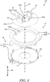
- FIG. 3 is a perspective view in which a fixed body 10 is removed from a rotation body 20 and the fixed body 10 is disassembled into a first fixed body portion 12 and a second fixed body portion 14.
- the rotary connector device 100 includes the fixed body 10 and the rotation body 20.
- the rotation body 20 is assembled to the fixed body 10 so as to be rotatable with respect to the fixed body 10 around a rotation axis AX.
- a first space S1 (see FIGS. 5 to 8 ) is defined between the fixed body 10 and the rotation body 20.
- a cable 30 is disposed in the first space S1.
- a first end 30a of the cable 30 is connected to the fixed body 10.
- a second end 30b of the cable 30 is connected to the rotation body 20.
- the rotary connector device 100 is used in, for example, a moving body (e.g., an automobile) including a main body and a steering portion rotatable with respect to the main body.
- a moving body e.g., an automobile
- the fixed body 10 is attached to the main body of the moving body.
- the rotation body 20 is attached to a steering portion.
- the first end 30a of the cable 30 is electrically connected to each electrical device provided in the main body of the moving body.
- the second end 30b of the cable 30 is electrically connected to electrical devices (e.g., a switch) provided in the steering portion.
- the rotary connector device 100 transmits and receives electric power or an electric signal between an electrical device provided in the main body of the moving body and an electrical device provided in the steering portion.
- the rotary connector device 100 may be used in a device other than the moving body.
- the fixed body 10 includes the first fixed body portion 12 and the second fixed body portion 14.
- the second fixed body portion 14 is coupled to the first fixed body portion 12 in a state of being disposed on the first fixed body portion 12.
- the first fixed body portion 12 has a ring shape when the rotary connector device 100 is viewed in an axial direction AD substantially parallel to the rotation axis AX.
- the first fixed body portion 12 is disposed such that the rotation axis AX passes through the center of the first fixed body portion 12.
- the second fixed body portion 14 includes an outer-circumferential cylindrical portion 140 and an inner flange portion 142.
- the outer-circumferential cylindrical portion 140 has a cylindrical shape in which a hollow portion 140a of the outer-circumferential cylindrical portion 140 extends in the axial direction AD.
- the outer-circumferential cylindrical portion 140 extends upward from an outer periphery 12a of the first fixed body portion 12 in the axial direction AD.
- the inner flange portion 142 extends from an inner peripheral surface 140b of the outer-circumferential cylindrical portion 140 in the radial direction of the rotation axis AX.
- the rotation body 20 includes an annular member 200 and an inner-circumferential cylindrical portion 210.
- the annular member 200 has a ring shape when the rotary connector device 100 is viewed in the axial direction AD.
- the annular member 200 is disposed such that the rotation axis AX passes through the center of the annular member 200.
- the annular member 200 is disposed such that an edge 200a of a bottom surface of the annular member faces the inner flange portion 142 in the axial direction AD.
- the inner-circumferential cylindrical portion 210 is disposed such that a hollow portion 210a of the inner-circumferential cylindrical portion 210 extends in the axial direction AD.
- the inner-circumferential cylindrical portion 210 extends downward from an inner periphery 200b of the annular member 200 along the axial direction AD.
- the inner-circumferential cylindrical portion 210 is disposed inside the outer-circumferential cylindrical portion 140 having a cylindrical shape in the radial direction of the rotation axis AX.
- the first space S1 in which the cable 30 is disposed is composed of the first fixed body portion 12, the outer-circumferential cylindrical portion 140, the annular member 200, and the inner-circumferential cylindrical portion 210.
- the first space S1 in which the cable 30 is disposed is equal to a space obtained by excluding the hollow portion 210a of the inner-circumferential cylindrical portion 210 from the hollow portion 140a of the outer-circumferential cylindrical portion 140.
- the inner-circumferential cylindrical portion 210 is provided in the rotation body 20. However, in order to define the first space S1, the inner-circumferential cylindrical portion 210 may be provided in the fixed body 10. Further, in the present embodiment, the rotary connector device 100 has the shape having the hollow portion 210a, but the rotary connector device 100 may not have the hollow portion 210a.
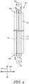
- FIG. 4 is a diagram illustrating a configuration of the cable 30.
- the cable 30 has flexibility.
- the cable 30 has a flat shape.
- the cable 30 includes a plurality of conductors 31 and a covering member 34 covering the plurality of conductors 31 and having insulating properties.
- the plurality of conductors 31 and the covering member 34 have a shape extending in one direction.
- the conductor 31 is made of a film of copper the thickness of which is equal to or less than 1 mm.
- the covering member 34 is made of resin (e.g., soft vinyl chloride).
- the materials of the conductor 31 and the covering member 34 are not limited thereto as long as the cable 30 has flexibility.
- the conductor 31 is exposed from the covering member 34 at the first end 30a and the second end 30b of the cable 30. That is, the conductor 31 has exposed conductor portions 32 provided at the first end 30a and the second end 30b of the cable 30.
- the cable 30 is wound along the inner peripheral surface 140b of the outer-circumferential cylindrical portion 140 in the first space S1.
- the rotary connector device 100 may further include a cable different from the cable 30.
- the rotary connector device 100 includes a connector 50 on the fixed body 10 side, a connector 60 on the rotation body 20 side, and a connector 66 on the rotation body 20 side.
- the connector 66 on the rotation body 20 side may be omitted.
- the connector 50 has a second space S2 inside and is coupled to the fixed body 10.
- the connector 50 includes a cover 52 and an electrode 58.
- the cover 52 includes a first cover portion 54 and a second cover portion 56.
- the first cover portion 54 extends downward in the axial direction AD and outward of the first fixed body portion 12 in the radial direction of the rotation axis AX from a part of the outer periphery 12a of the first fixed body portion 12.
- the second cover portion 56 extends downward in the axial direction AD and outward of the outer-circumferential cylindrical portion 140 in the radial direction of the rotation axis AX from a part of the outer-circumferential cylindrical portion 140.
- the first fixed body portion 12 and the second fixed body portion 14 are coupled to each other, and the first cover portion 54 and the second cover portion 56 are coupled to each other, thereby forming the second space S2.
- the second space S2 is open downward in the axial direction AD.
- the shape of the cover 52 is not limited thereto.
- the cover 52 may have a cylindrical shape that extends outward from the outer-circumferential cylindrical portion 140 in the radial direction of the rotation axis AX and opens an internal space in the radial direction of the rotation axis AX.
- the electrode 58 is disposed in the cover 52 in the second space S2. That is, the electrode 58 is covered with the cover 52.
- An exposed conductor portion 32 is exposed from the covering member 34 at the first end 30a of the cable 30.
- the exposed conductor portion 32 of the conductor 31 is connected to the electrode 58 in the second space S2 (see FIG. 6 ).
- Each of the plurality of electrodes 58 has a terminal portion, and the terminal portion is connected to a terminal of a cable connected to a controller provided in a main body of the moving body. However, the terminal portion may be electrically connected to the electrode 58, and the terminal portion and the electrode 58 may be provided separately.
- the connector 60 is coupled to the annular member 200.
- the connector 60 includes electrodes 62 (see FIG. 4 ) and a cover that covers the electrodes 62.
- the exposed conductor portion 32 exposed from the covering member 34 at the second end 30b of the cable 30 is connected to the electrodes 62 of the connector 60.
- FIG. 5 is a perspective view of the second fixed body portion 14 for illustrating the arrangement of the cable 30.
- FIG. 6 is a perspective view of the second fixed body portion 14 for illustrating a tensile load F1 applied to the exposed conductor portion 32 of the cable 30.
- FIG. 7 is a cross-sectional view of the second fixed body portion 14 for illustrating the length of a cable cutting member 500.
- FIG. 8 is a cross-sectional view of the second fixed body portion 14 for illustrating a shearing load F2 applied to a contact portion 36 of the cable 30.
- FIGS. 7 and 8 are cross-sectional views of the second fixed body portion 14 in a direction orthogonal to the rotation axis AX.
- the cable 30 is disposed in the connector 50 and the fixed body 10 so as to extend from the second space S2 to the first space S1 in a bent state.
- the exposed conductor portion 32 and the electrode 58 are connected to each other in a state where the direction in which the cable 30 at the first end 30a extends and the direction in which the electrode 58 of the connector 50 extends coincide with each other.
- This connection is realized, for example, by crimping or by bonding via solder.
- the direction in which the electrode 58 extends is along the axial direction AD, but is not limited thereto.
- the connector 50 includes the cable cutting member 500 in the second space S2 in order to cut the cable 30 in the second space S2.
- the cable cutting member 500 is covered by the second cover portion 56.
- the second cover portion 56 includes a first wall 560, a second wall 562, and a third wall 564.
- the first wall 560 extends outward from the outer-circumferential cylindrical portion 140 in a direction orthogonal to the rotation axis AX.
- the second wall 562 extends outward from the outer-circumferential cylindrical portion 140 in a direction orthogonal to the rotation axis AX.
- the third wall 564 extends in the circumferential direction of the rotation axis AX and connects the first wall 560 and the second wall 562.
- the outer-circumferential cylindrical portion 140 may also be referred to as a wall portion 140.
- the wall portion 140 is spaced apart from the cable cutting member 500.
- the wall portion 140 is disposed radially inward of the cable cutting member 500 with respect to the rotation axis AX.
- the cable cutting member 500 has a wall shape extending along the axial direction AD.
- the cable cutting member 500 extends from the first wall 560 in an extending direction ED (see FIG. 7 ) along the circumferential direction of the rotation axis AX.
- the cable cutting member 500 does not reach the second wall 562 in the extending direction ED in order to provide a routing path R of the cable 30.
- the extending direction ED is along a direction opposite to a tension direction in which the cable 30 is pulled from the second space S2 to the first space S1 due to the rotation of the rotation body 20. In this way, by providing the extending direction ED in which the cable cutting member 500 extends, the shearing load F2 described later can be increased.
- a length L of the cable cutting member 500 in the extending direction ED is set such that a tip 510 of the cable cutting member 500 in the extending direction ED comes into contact with the cable 30 when the cable 30 is pulled due to the rotation of the rotation body 20.
- the length L of the cable cutting member 500 is provided such that the cable cutting member 500 intersects an imaginary line IL.
- the imaginary line IL connects the electrode 58 of the connector 50 and an opening OP.
- the opening OP is provided in the outer-circumferential cylindrical portion 140 and opens the second space S2 to the first space S1.
- the length L is preferably as large as possible in order to increase the shearing load F2 described later.
- the length L is 1/4 or more of the length of the third wall 564 in the extending direction ED.
- the length L is equal to or greater than the length of the first wall 560 in the radial direction of the rotation axis AX.
- the length L is not limited thereto.
- the routing path R includes a path R1, a path R2, and a path R3.
- the path R1 extends from the first wall 560 toward the tip 510 of the cable cutting member 500 in the extending direction ED.
- the path R1 is provided between the cable cutting member 500 and the third wall 564 in the radial direction of the rotation axis AX.
- the path R2 extends around the tip 510 of the cable cutting member 500 in the extending direction ED.
- the path R2 is provided between the tip 510 and the second wall 562 in the extending direction ED.
- the path R3 extends from the tip 510 toward the first wall 560 in a direction opposite to the extending direction ED.
- the path R3 is provided between the outer-circumferential cylindrical portion 140 and the cable cutting member 500 in the radial direction of the rotation axis AX. That is, at least a part of the routing path R is provided between the cable cutting member 500 and the wall portion 140.
- the cable 30 is disposed in the second space S2 in a state of being folded twice so as to be along the routing path R.
- the cable 30 extends upward from the first end 30a along the axial direction AD, extends along the extending direction ED, is folded at the tip 510, and extends in a direction opposite to the extending direction ED.
- the cable 30 passes through the opening OP and extends from the second space S2 to the first space S1. Then, the cable 30 passes through an opening provided in the inner-circumferential cylindrical portion 210, and the second end 30b is connected to the connector 60.
- the cable 30 is excessively pulled.
- the cable 30 is configured to be cut by the cable cutting member 500 before the exposed conductor portion 32 connected to the electrode 58 is disconnected (so as not to be disconnected) when the cable 30 is excessively pulled due to the rotation of the rotation body 20.
- the tensile load F1 is applied upward to the exposed conductor portion 32 of the cable 30 at the first end 30a along the axial direction AD.
- the contact portion 36 of the cable 30 contacts the tip 510 in the second space S2, and the shearing load F2 is applied to the contact portion 36 in a direction opposite to the tension direction.
- the tensile load F1 for removing the exposed conductor portion 32 from the electrode 58 is larger than the shearing load F2 for cutting the cable 30 at the contact portion 36.
- the cable cutting member 500 is provided so that the cable 30 is accommodated in the second space S2 in a bent state.
- the tensile load F1 is three times the value of the tensile load for removing one exposed conductor portion 32 from one electrode 58.
- the cable 30 When the cable 30 is excessively pulled due to the rotation of the rotation body 20, the cable 30 is cut at the contact portion 36 without disconnecting the exposed conductor portion 32 connected to the electrode 58. Thereby, in the second space S2, the exposed conductor portion 32 exposed from the covering member 34 at the first end 30a is suppressed, for example, from coming into contact with an electrode other than the electrode 58. In addition, for example, the exposed conductor portion 32 exposed from the covering member 34 at the first end 30a is suppressed from being shortcircuited to a conductor of a cable other than the cable 30.
- the cable 30 can be cut at the contact portion 36 with a simple structure.
- the structure of the cable cutting member 500 for cutting the cable 30 is not limited to that illustrated in FIGS. 5 to 8 .
- FIG. 9 is a cross-sectional view of the second fixed body portion 14 for illustrating a cable cutting member 500A according to a modified example of the cable cutting member 500.
- the cable cutting member 500A has an acute-angled tip 510A in the extending direction ED. Therefore, the cable 30 is easily cut at the contact portion 36.
- FIG. 10 is a diagram illustrating a configuration of a cable 30A according to a modified example of the cable 30. As illustrated in FIG. 10 , the cable 30A differs from the cable 30 illustrated in FIG. 4 in that it has a notch 36A at the contact portion 36.
- the notch 36A cuts the covering member 34 in the thickness direction of the cable 30A.
- a plurality of notches 36A are provided along a width direction WD of the cable 30A.
- the thickness direction of the cable 30A is a direction orthogonal to a flat surface of the cable 30A.
- the width direction WD of the cable 30A is a direction orthogonal to the direction in which the cable 30A extends and to the thickness direction of the cable 30A.
- the plurality of notches 36A are provided so as to avoid the plurality of conductors 31.
- the cable 30A is provided with the plurality of notches 36A, the cable 30A is easily cut by the cable cutting member 500 at the contact portion 36.
- a number such as “first” or “second” is merely a term for identifying a configuration, and does not have any other meaning (e.g., a particular order, or the like).
- the presence of, for example, a “first element” does not imply that a “second element” exists, and the presence of a “second element” does not imply that a "first element” exists.
- the expression "at least one of A and B" in the present disclosure includes any of the following three cases. (i) includes only A, (ii) includes only B, and (iii) includes both A and B.
Landscapes
- Engineering & Computer Science (AREA)
- Mechanical Engineering (AREA)
- Chemical & Material Sciences (AREA)
- Combustion & Propulsion (AREA)
- Transportation (AREA)
- Electric Cable Arrangement Between Relatively Moving Parts (AREA)
- Details Of Connecting Devices For Male And Female Coupling (AREA)
- Steering Controls (AREA)
Abstract
Description
- The technology disclosed in the present application relates to a rotary connector device.
- A known rotary connector device includes: a fixed body, a rotation body that is rotatably attached to the fixed body, a connector connected to the fixed body, and a cable placed in a space between the fixed body and the rotation body (e.g., see Patent Document 1). In the rotary connector device described in
Patent Document 1, one end of the cable is connected to the fixed body, and the other end of the cable is connected to the rotation body. - Patent Document 1:
JP 2004-222369 A - In the rotary connector device disclosed in
Patent Document 1, when the cable is pulled and the cable is disconnected in the connector connected to one end of the cable, an electrical problem may occur. - Therefore, an object of the technology disclosed in the present application is to improve the electrical reliability of the rotary connector device.
- A rotary connector device according to a first feature of the present application includes: a fixed body; a rotation body that is rotatable about a rotation axis with respect to the fixed body and that is assembled to the fixed body in a manner to form a first space between the rotation body and the fixed body; and a connector that has a second space inside communicating with the first space and that is coupled to the fixed body. An exposed conductor portion provided at one end of a cable is connected to an electrode provided in the second space of the connector. The cable extends from the second space to the first space and is arranged such that the other end of the cable is connected to the rotation body. The connector includes a cable cutting member in the second space. When the cable is pulled due to rotation of the rotation body, the cable cutting member is configured to cut the cable before the exposed conductor portion connected to the electrode of the connector is disconnected.
- In this configuration, disconnection of the exposed conductor portion provided at the one end of the cable can be suppressed. Therefore, the exposed conductor portion at the one end of the cable does not come into contact with another conductor in the first space and the second space to cause a short-circuit.
- Further, the cable cutting member may be configured to come into contact with a contact portion other than the exposed conductor portion of the cable, and a tensile load that is applied to the exposed conductor portion to disconnect the exposed conductor portion in the connector may be larger than a shearing load that is applied to the contact portion for the cable cutting member to cut the cable at the contact portion.
- In this configuration, it is only necessary to adjust the tensile load and the shearing load. Therefore, the structure in the connector can be simplified.
- Moreover, the connector may be coupled to the fixed body in a direction substantially orthogonal to the rotation axis, a tension direction in which the cable is pulled may be along a circumferential direction of the rotation axis, the cable cutting member may have a wall shape extending along an opposite direction to the tension direction, and when the cable is pulled in the tension direction, the cable cutting member may come into contact with the contact portion, at a tip of the cable cutting member in the opposite direction.
- In this configuration, the wall (cable cutting member) extends in an opposite direction to a direction in which a large shearing load is applied. Accordingly, this configuration can more reliably cut the cable at the contact portion.
- Additionally, the tip of the cable cutting member in the opposite direction may have an acute-angled shape in a cross-section orthogonal to the rotation axis.
- This configuration allows the cable to be more reliably cut at the contact portion.
- In addition, the rotary connector device may include a cable in which a notch is provided in the contact portion.
- This configuration allows the cable to be more reliably cut at the contact portion.
- Additionally, the fixed body includes a wall portion disposed at a distance from the cable cutting member.
- Thus, when the cable is cut, a short-circuit at the cut portion can be suppressed.
- Further, the fixed body has a routing path in which the cable is provided. At least a part of the routing path is provided between the cable cutting member and the wall portion.
- Thus, when the cable is cut, a short-circuit at the cut portion can be more reliably suppressed.
- Moreover, the wall portion is disposed radially inward of the cable cutting member with respect to the rotation axis.
- Thus, when the cable is cut, a short-circuit at the cut portion can be more reliably suppressed.
- The cable cutting member is provided such that the cable is accommodated in a bent state in the second space.
- Thus, the cable can be efficiently accommodated in the second space.
- According to the technology disclosed in the present application, the electrical reliability of the rotary connector device can be improved.
-
-
FIG. 1 is a perspective view of a rotary connector device according to an embodiment. -
FIG. 2 is a bottom view of the rotary connector device. -
FIG. 3 is a perspective view in which a fixed body is removed from a rotation body and the fixed body is disassembled into a first fixed body portion and a second fixed body portion. -
FIG. 4 is a diagram illustrating a configuration of a cable. -
FIG. 5 is a perspective view of the second fixed body portion for illustrating the arrangement of the cable. -
FIG. 6 is a perspective view of the second fixed body portion for illustrating a tensile load applied to an exposed conductor portion of the cable. -
FIG. 7 is a cross-sectional view of the second fixed body portion for illustrating the length of a cable cutting member. -
FIG. 8 is a cross-sectional view of the second fixed body portion for illustrating a shearing load applied to a contact portion of the cable. -
FIG. 9 is a cross-sectional view of the second fixed body portion for illustrating a cable cutting member according to a modified example of the cable cutting member. -
FIG. 10 is a diagram illustrating a configuration of a cable according to a modified example of the cable. - Hereinafter, embodiments will be described with reference to the drawings. In the figures, the same reference signs denote corresponding or identical components.
-
FIG. 1 is a perspective view of arotary connector device 100 according to an embodiment.FIG. 2 is a bottom view of therotary connector device 100.FIG. 3 is a perspective view in which afixed body 10 is removed from arotation body 20 and thefixed body 10 is disassembled into a first fixedbody portion 12 and a second fixedbody portion 14. - As illustrated in
FIGS. 1 to 3 , therotary connector device 100 includes thefixed body 10 and therotation body 20. Therotation body 20 is assembled to thefixed body 10 so as to be rotatable with respect to thefixed body 10 around a rotation axis AX. In a state where therotation body 20 is assembled to thefixed body 10, a first space S1 (seeFIGS. 5 to 8 ) is defined between thefixed body 10 and therotation body 20. - A
cable 30 is disposed in the first space S1. Afirst end 30a of thecable 30 is connected to the fixedbody 10. Asecond end 30b of thecable 30 is connected to therotation body 20. - The
rotary connector device 100 is used in, for example, a moving body (e.g., an automobile) including a main body and a steering portion rotatable with respect to the main body. Specifically, thefixed body 10 is attached to the main body of the moving body. Therotation body 20 is attached to a steering portion. Thefirst end 30a of thecable 30 is electrically connected to each electrical device provided in the main body of the moving body. Thesecond end 30b of thecable 30 is electrically connected to electrical devices (e.g., a switch) provided in the steering portion. Thus, therotary connector device 100 transmits and receives electric power or an electric signal between an electrical device provided in the main body of the moving body and an electrical device provided in the steering portion. However, therotary connector device 100 may be used in a device other than the moving body. - As illustrated in
FIGS. 1 and3 , the fixedbody 10 includes the firstfixed body portion 12 and the secondfixed body portion 14. The secondfixed body portion 14 is coupled to the firstfixed body portion 12 in a state of being disposed on the firstfixed body portion 12. - As illustrated in
FIG. 3 , the firstfixed body portion 12 has a ring shape when therotary connector device 100 is viewed in an axial direction AD substantially parallel to the rotation axis AX. The firstfixed body portion 12 is disposed such that the rotation axis AX passes through the center of the firstfixed body portion 12. - The second
fixed body portion 14 includes an outer-circumferentialcylindrical portion 140 and aninner flange portion 142. The outer-circumferentialcylindrical portion 140 has a cylindrical shape in which ahollow portion 140a of the outer-circumferentialcylindrical portion 140 extends in the axial direction AD. The outer-circumferentialcylindrical portion 140 extends upward from anouter periphery 12a of the firstfixed body portion 12 in the axial direction AD. Theinner flange portion 142 extends from an innerperipheral surface 140b of the outer-circumferentialcylindrical portion 140 in the radial direction of the rotation axis AX. - The
rotation body 20 includes anannular member 200 and an inner-circumferentialcylindrical portion 210. Theannular member 200 has a ring shape when therotary connector device 100 is viewed in the axial direction AD. Theannular member 200 is disposed such that the rotation axis AX passes through the center of theannular member 200. Theannular member 200 is disposed such that anedge 200a of a bottom surface of the annular member faces theinner flange portion 142 in the axial direction AD. The inner-circumferentialcylindrical portion 210 is disposed such that ahollow portion 210a of the inner-circumferentialcylindrical portion 210 extends in the axial direction AD. The inner-circumferentialcylindrical portion 210 extends downward from aninner periphery 200b of theannular member 200 along the axial direction AD. The inner-circumferentialcylindrical portion 210 is disposed inside the outer-circumferentialcylindrical portion 140 having a cylindrical shape in the radial direction of the rotation axis AX. Thus, the first space S1 in which thecable 30 is disposed is composed of the firstfixed body portion 12, the outer-circumferentialcylindrical portion 140, theannular member 200, and the inner-circumferentialcylindrical portion 210. In other words, the first space S1 in which thecable 30 is disposed is equal to a space obtained by excluding thehollow portion 210a of the inner-circumferentialcylindrical portion 210 from thehollow portion 140a of the outer-circumferentialcylindrical portion 140. - In the present embodiment, the inner-circumferential
cylindrical portion 210 is provided in therotation body 20. However, in order to define the first space S1, the inner-circumferentialcylindrical portion 210 may be provided in the fixedbody 10. Further, in the present embodiment, therotary connector device 100 has the shape having thehollow portion 210a, but therotary connector device 100 may not have thehollow portion 210a. -
FIG. 4 is a diagram illustrating a configuration of thecable 30. Thecable 30 has flexibility. Thecable 30 has a flat shape. Thecable 30 includes a plurality ofconductors 31 and a coveringmember 34 covering the plurality ofconductors 31 and having insulating properties. The plurality ofconductors 31 and the coveringmember 34 have a shape extending in one direction. For example, theconductor 31 is made of a film of copper the thickness of which is equal to or less than 1 mm. For example, the coveringmember 34 is made of resin (e.g., soft vinyl chloride). However, the materials of theconductor 31 and the coveringmember 34 are not limited thereto as long as thecable 30 has flexibility. - The
conductor 31 is exposed from the coveringmember 34 at thefirst end 30a and thesecond end 30b of thecable 30. That is, theconductor 31 has exposedconductor portions 32 provided at thefirst end 30a and thesecond end 30b of thecable 30. Thecable 30 is wound along the innerperipheral surface 140b of the outer-circumferentialcylindrical portion 140 in the first space S1. - In the example illustrated in
FIG. 4 , threeconductors 31 are provided in thecable 30, but the number ofconductors 31 is not limited thereto. Therotary connector device 100 may further include a cable different from thecable 30. - As illustrated in
FIG. 1 , therotary connector device 100 includes aconnector 50 on the fixedbody 10 side, aconnector 60 on therotation body 20 side, and aconnector 66 on therotation body 20 side. However, theconnector 66 on therotation body 20 side may be omitted. - As illustrated in
FIGS. 1 and2 , theconnector 50 has a second space S2 inside and is coupled to the fixedbody 10. As illustrated inFIG. 2 , theconnector 50 includes acover 52 and anelectrode 58. As illustrated inFIG. 3 , thecover 52 includes a first cover portion 54 and asecond cover portion 56. As illustrated inFIG. 3 , the first cover portion 54 extends downward in the axial direction AD and outward of the firstfixed body portion 12 in the radial direction of the rotation axis AX from a part of theouter periphery 12a of the firstfixed body portion 12. Thesecond cover portion 56 extends downward in the axial direction AD and outward of the outer-circumferentialcylindrical portion 140 in the radial direction of the rotation axis AX from a part of the outer-circumferentialcylindrical portion 140. The firstfixed body portion 12 and the secondfixed body portion 14 are coupled to each other, and the first cover portion 54 and thesecond cover portion 56 are coupled to each other, thereby forming the second space S2. The second space S2 is open downward in the axial direction AD. However, the shape of thecover 52 is not limited thereto. For example, thecover 52 may have a cylindrical shape that extends outward from the outer-circumferentialcylindrical portion 140 in the radial direction of the rotation axis AX and opens an internal space in the radial direction of the rotation axis AX. - As illustrated in
FIG. 2 , theelectrode 58 is disposed in thecover 52 in the second space S2. That is, theelectrode 58 is covered with thecover 52. An exposedconductor portion 32 is exposed from the coveringmember 34 at thefirst end 30a of thecable 30. The exposedconductor portion 32 of theconductor 31 is connected to theelectrode 58 in the second space S2 (seeFIG. 6 ). Each of the plurality ofelectrodes 58 has a terminal portion, and the terminal portion is connected to a terminal of a cable connected to a controller provided in a main body of the moving body. However, the terminal portion may be electrically connected to theelectrode 58, and the terminal portion and theelectrode 58 may be provided separately. - The
connector 60 is coupled to theannular member 200. Theconnector 60 includes electrodes 62 (seeFIG. 4 ) and a cover that covers theelectrodes 62. The exposedconductor portion 32 exposed from the coveringmember 34 at thesecond end 30b of thecable 30 is connected to theelectrodes 62 of theconnector 60. - Next, the arrangement of the
cable 30 from the second space S2 to the first space S1 will be described with reference toFIGS. 5 to 8 .FIG. 5 is a perspective view of the secondfixed body portion 14 for illustrating the arrangement of thecable 30.FIG. 6 is a perspective view of the secondfixed body portion 14 for illustrating a tensile load F1 applied to the exposedconductor portion 32 of thecable 30.FIG. 7 is a cross-sectional view of the secondfixed body portion 14 for illustrating the length of acable cutting member 500.FIG. 8 is a cross-sectional view of the secondfixed body portion 14 for illustrating a shearing load F2 applied to acontact portion 36 of thecable 30. However,FIGS. 7 and8 are cross-sectional views of the secondfixed body portion 14 in a direction orthogonal to the rotation axis AX. - As illustrated in
FIGS. 5 and8 , thecable 30 is disposed in theconnector 50 and the fixedbody 10 so as to extend from the second space S2 to the first space S1 in a bent state. As illustrated inFIGS. 5 and6 , the exposedconductor portion 32 and theelectrode 58 are connected to each other in a state where the direction in which thecable 30 at thefirst end 30a extends and the direction in which theelectrode 58 of theconnector 50 extends coincide with each other. This connection is realized, for example, by crimping or by bonding via solder. However, in the example illustrated inFIG. 5 , the direction in which theelectrode 58 extends is along the axial direction AD, but is not limited thereto. - As illustrated in
FIGS. 5 to 8 , theconnector 50 includes thecable cutting member 500 in the second space S2 in order to cut thecable 30 in the second space S2. Thecable cutting member 500 is covered by thesecond cover portion 56. More specifically, thesecond cover portion 56 includes afirst wall 560, asecond wall 562, and athird wall 564. Thefirst wall 560 extends outward from the outer-circumferentialcylindrical portion 140 in a direction orthogonal to the rotation axis AX. Thesecond wall 562 extends outward from the outer-circumferentialcylindrical portion 140 in a direction orthogonal to the rotation axis AX. Thethird wall 564 extends in the circumferential direction of the rotation axis AX and connects thefirst wall 560 and thesecond wall 562. As a result, a space surrounded by the outer-circumferentialcylindrical portion 140, thefirst wall 560, thesecond wall 562, and thethird wall 564 is formed. This space is a part of the second space S2. The outer-circumferentialcylindrical portion 140 may also be referred to as awall portion 140. Thewall portion 140 is spaced apart from thecable cutting member 500. Thewall portion 140 is disposed radially inward of thecable cutting member 500 with respect to the rotation axis AX. - As illustrated in
FIGS. 5 to 8 , thecable cutting member 500 has a wall shape extending along the axial direction AD. Thecable cutting member 500 extends from thefirst wall 560 in an extending direction ED (seeFIG. 7 ) along the circumferential direction of the rotation axis AX. However, thecable cutting member 500 does not reach thesecond wall 562 in the extending direction ED in order to provide a routing path R of thecable 30. Further, the extending direction ED is along a direction opposite to a tension direction in which thecable 30 is pulled from the second space S2 to the first space S1 due to the rotation of therotation body 20. In this way, by providing the extending direction ED in which thecable cutting member 500 extends, the shearing load F2 described later can be increased. - A length L of the
cable cutting member 500 in the extending direction ED is set such that atip 510 of thecable cutting member 500 in the extending direction ED comes into contact with thecable 30 when thecable 30 is pulled due to the rotation of therotation body 20. For example, as illustrated inFIG. 7 , the length L of thecable cutting member 500 is provided such that thecable cutting member 500 intersects an imaginary line IL. However, the imaginary line IL connects theelectrode 58 of theconnector 50 and an opening OP. The opening OP is provided in the outer-circumferentialcylindrical portion 140 and opens the second space S2 to the first space S1. The length L is preferably as large as possible in order to increase the shearing load F2 described later. - For example, the length L is 1/4 or more of the length of the
third wall 564 in the extending direction ED. For example, the length L is equal to or greater than the length of thefirst wall 560 in the radial direction of the rotation axis AX. However, the length L is not limited thereto. - As illustrated in
FIG. 7 , the routing path R includes a path R1, a path R2, and a path R3. The path R1 extends from thefirst wall 560 toward thetip 510 of thecable cutting member 500 in the extending direction ED. The path R1 is provided between thecable cutting member 500 and thethird wall 564 in the radial direction of the rotation axis AX. The path R2 extends around thetip 510 of thecable cutting member 500 in the extending direction ED. The path R2 is provided between thetip 510 and thesecond wall 562 in the extending direction ED. The path R3 extends from thetip 510 toward thefirst wall 560 in a direction opposite to the extending direction ED. The path R3 is provided between the outer-circumferentialcylindrical portion 140 and thecable cutting member 500 in the radial direction of the rotation axis AX. That is, at least a part of the routing path R is provided between thecable cutting member 500 and thewall portion 140. - As illustrated in
FIG. 5 , thecable 30 is disposed in the second space S2 in a state of being folded twice so as to be along the routing path R. To be specific, in the second space S2, thecable 30 extends upward from thefirst end 30a along the axial direction AD, extends along the extending direction ED, is folded at thetip 510, and extends in a direction opposite to the extending direction ED. However, it is not essential that thecable 30 be folded, and thecable 30 may be bent only twice in order to follow the routing path R. Thecable 30 passes through the opening OP and extends from the second space S2 to the first space S1. Then, thecable 30 passes through an opening provided in the inner-circumferentialcylindrical portion 210, and thesecond end 30b is connected to theconnector 60. - When the
rotation body 20 rotates by a limited rotation angle or more with respect to the fixedbody 10, thecable 30 is excessively pulled. In the present embodiment, thecable 30 is configured to be cut by thecable cutting member 500 before the exposedconductor portion 32 connected to theelectrode 58 is disconnected (so as not to be disconnected) when thecable 30 is excessively pulled due to the rotation of therotation body 20. - More specifically, when the
cable 30 is pulled, as illustrated inFIG. 6 , the tensile load F1 is applied upward to the exposedconductor portion 32 of thecable 30 at thefirst end 30a along the axial direction AD. As illustrated inFIG. 8 , thecontact portion 36 of thecable 30 contacts thetip 510 in the second space S2, and the shearing load F2 is applied to thecontact portion 36 in a direction opposite to the tension direction. In the present embodiment, the tensile load F1 for removing the exposedconductor portion 32 from theelectrode 58 is larger than the shearing load F2 for cutting thecable 30 at thecontact portion 36. Thecable cutting member 500 is provided so that thecable 30 is accommodated in the second space S2 in a bent state. - In the present embodiment, three exposed
conductor portions 32 are connected to threeelectrodes 58. Therefore, the tensile load F1 is three times the value of the tensile load for removing one exposedconductor portion 32 from oneelectrode 58. - When the
cable 30 is excessively pulled due to the rotation of therotation body 20, thecable 30 is cut at thecontact portion 36 without disconnecting the exposedconductor portion 32 connected to theelectrode 58. Thereby, in the second space S2, the exposedconductor portion 32 exposed from the coveringmember 34 at thefirst end 30a is suppressed, for example, from coming into contact with an electrode other than theelectrode 58. In addition, for example, the exposedconductor portion 32 exposed from the coveringmember 34 at thefirst end 30a is suppressed from being shortcircuited to a conductor of a cable other than thecable 30. - Further, since it is only necessary to adjust the tensile load F1 and the shearing load F2, the
cable 30 can be cut at thecontact portion 36 with a simple structure. However, the structure of thecable cutting member 500 for cutting thecable 30 is not limited to that illustrated inFIGS. 5 to 8 . -
FIG. 9 is a cross-sectional view of the secondfixed body portion 14 for illustrating acable cutting member 500A according to a modified example of thecable cutting member 500. Thecable cutting member 500A has an acute-angledtip 510A in the extending direction ED. Therefore, thecable 30 is easily cut at thecontact portion 36. -
FIG. 10 is a diagram illustrating a configuration of acable 30A according to a modified example of thecable 30. As illustrated inFIG. 10 , thecable 30A differs from thecable 30 illustrated inFIG. 4 in that it has anotch 36A at thecontact portion 36. - As illustrated in
FIG. 10 , thenotch 36A cuts the coveringmember 34 in the thickness direction of thecable 30A. In the example illustrated inFIG. 10 , a plurality ofnotches 36A are provided along a width direction WD of thecable 30A. Note that the thickness direction of thecable 30A is a direction orthogonal to a flat surface of thecable 30A. The width direction WD of thecable 30A is a direction orthogonal to the direction in which thecable 30A extends and to the thickness direction of thecable 30A. As illustrated inFIG. 10 , the plurality ofnotches 36A are provided so as to avoid the plurality ofconductors 31. - Since the
cable 30A is provided with the plurality ofnotches 36A, thecable 30A is easily cut by thecable cutting member 500 at thecontact portion 36. - It should be noted that, in the present application, "comprise" and its derivatives are non-limiting terms describing the presence of a component and do not exclude the presence of other components not described. This also applies to "have", "include" and their derivatives.
- In the present application, a number such as "first" or "second" is merely a term for identifying a configuration, and does not have any other meaning (e.g., a particular order, or the like). The presence of, for example, a "first element" does not imply that a "second element" exists, and the presence of a "second element" does not imply that a "first element" exists.
- Expressions such as "parallel", "orthogonal", and "identical" in the present disclosure should not be interpreted strictly and include respectively the meanings of "substantially parallel", "substantially orthogonal", and "substantially identical". Further, representations of other arrangements are not to be strictly interpreted.
- The expression "at least one of A and B" in the present disclosure includes any of the following three cases. (i) includes only A, (ii) includes only B, and (iii) includes both A and B.
- Various alterations and modifications of the present invention are apparent from the foregoing disclosure. Accordingly, the present invention may be implemented in a manner different from the specific disclosure of the present application without departing from the spirit of the present invention.
-
- 100 Rotary connector device
- 10 Fixed body
- 20 Rotation body
- 30 Cable
- 31 Conductor
- 32 Exposed conductor portion
- 50 Connector
- 58 Electrode
- 500 Cable cutting member
Claims (9)
- A rotary connector device comprising:a fixed body;a rotation body that is rotatable about a rotation axis with respect to the fixed body and that is assembled to the fixed body in a manner to form a first space between the rotation body and the fixed body; anda connector that has a second space inside communicating with the first space and that is coupled to the fixed body, whereinan exposed conductor portion provided at one end of a cable is connected to an electrode provided in the second space of the connector,the cable extends from the second space to the first space and is arranged such that the other end of the cable is connected to the rotation body,the connector comprises a cable cutting member in the second space, andwhen the cable is pulled due to rotation of the rotation body, the cable cutting member is configured to cut the cable before the exposed conductor portion connected to the electrode of the connector is disconnected.
- The rotary connector device according to claim 1, wherein
the cable cutting member is configured to come into contact with a contact portion other than the exposed conductor portion of the cable, and
a tensile load that is applied to the exposed conductor portion to disconnect the exposed conductor portion in the connector is larger than a shearing load that is applied to the contact portion for the cable cutting member to cut the cable at the contact portion. - The rotary connector device according to claim 1 or 2, wherein
the connector is coupled to the fixed body in a direction substantially orthogonal to the rotation axis,
a tension direction in which the cable is pulled is along a circumferential direction of the rotation axis,
the cable cutting member has a wall shape extending along an opposite direction to the tension direction, and
when the cable is pulled in the tension direction, the cable cutting member comes into contact with the contact portion other than the exposed conductor portion of the cable, at a tip of the cable cutting member in the opposite direction. - The rotary connector device according to claim 3, wherein
the tip of the cable cutting member in the opposite direction has an acute-angled shape in a cross-section perpendicular to a direction orthogonal to the rotation axis. - The rotary connector device according to any one of claims 1 to 4, further comprising
the cable comprising a contact portion that comes into contact with the cable cutting member when the cable is pulled due to rotation of the rotation body, wherein
the contact portion is provided with a notch. - The rotary connector device according to any one of claims 1 to 5, wherein
the fixed body comprises a wall portion disposed at a distance from the cable cutting member. - The rotary connector device according to claim 6, wherein
the fixed body has a routing path in which the cable is provided, and
at least a part of the routing path is provided between the cable cutting member and the wall portion. - The rotary connector device according to claim 6 or 7, wherein
the wall portion is disposed radially inward of the cable cutting member with respect to the rotation axis. - The rotary connector device according to any one of claims 1 to 8, wherein
the cable cutting member is provided such that the cable is accommodated in a bent state in the second space.
Applications Claiming Priority (2)
| Application Number | Priority Date | Filing Date | Title |
|---|---|---|---|
| JP2018190244 | 2018-10-05 | ||
| PCT/JP2019/039168 WO2020071496A1 (en) | 2018-10-05 | 2019-10-03 | Rotary connector device |
Publications (3)
| Publication Number | Publication Date |
|---|---|
| EP3859910A1 true EP3859910A1 (en) | 2021-08-04 |
| EP3859910A4 EP3859910A4 (en) | 2021-11-17 |
| EP3859910B1 EP3859910B1 (en) | 2023-05-10 |
Family
ID=70055202
Family Applications (1)
| Application Number | Title | Priority Date | Filing Date |
|---|---|---|---|
| EP19870015.5A Active EP3859910B1 (en) | 2018-10-05 | 2019-10-03 | Rotary connector device |
Country Status (6)
| Country | Link |
|---|---|
| US (1) | US11431139B2 (en) |
| EP (1) | EP3859910B1 (en) |
| JP (1) | JP7335888B2 (en) |
| KR (1) | KR20210060592A (en) |
| CN (1) | CN112753141A (en) |
| WO (1) | WO2020071496A1 (en) |
Family Cites Families (17)
| Publication number | Priority date | Publication date | Assignee | Title |
|---|---|---|---|---|
| DE3732124A1 (en) * | 1987-09-24 | 1989-04-13 | Kabelmetal Electro Gmbh | DEVICE FOR TRANSMITTING ELECTRICITY BETWEEN TWO RELATIVELY MOVABLE CONTACTS |
| JPH0321544A (en) * | 1989-06-15 | 1991-01-30 | Daihatsu Motor Co Ltd | Wiring device |
| JP2538866Y2 (en) * | 1991-11-15 | 1997-06-18 | 古河電気工業株式会社 | Rotating connector |
| US5226230A (en) * | 1991-12-13 | 1993-07-13 | Itt Corporation | Universal o.d. release tool |
| US5429517A (en) * | 1994-02-14 | 1995-07-04 | Methode Electronics, Inc. | Two-piece clockspring with lock and wire harness assembly |
| JPH1092541A (en) * | 1996-09-13 | 1998-04-10 | Furukawa Electric Co Ltd:The | Rotation connector |
| JP2000306649A (en) * | 1999-04-23 | 2000-11-02 | Alps Electric Co Ltd | Rotary connector |
| JP4234446B2 (en) | 2003-01-10 | 2009-03-04 | 古河電気工業株式会社 | Rotating connector device |
| US7190385B2 (en) * | 2004-04-02 | 2007-03-13 | Agfa-Gevaert N.V. | Thermal printing method |
| JP4891701B2 (en) * | 2006-08-23 | 2012-03-07 | ナイルス株式会社 | Rotating connector device |
| JP2009080958A (en) * | 2007-09-25 | 2009-04-16 | Alps Electric Co Ltd | Rotating connector |
| JP5671746B2 (en) * | 2011-03-24 | 2015-02-18 | アルプス電気株式会社 | Rotating connector |
| JP5817627B2 (en) | 2012-04-05 | 2015-11-18 | トヨタ自動車株式会社 | Electric vehicle |
| CN103378526B (en) * | 2012-04-11 | 2015-05-27 | 阿尔卑斯电气株式会社 | Rotation connector |
| JP5886148B2 (en) * | 2012-06-21 | 2016-03-16 | 株式会社ヴァレオジャパン | Rotating connector device |
| JP2016213093A (en) * | 2015-05-11 | 2016-12-15 | アルプス電気株式会社 | Rotary connector |
| JP6767770B2 (en) * | 2016-04-28 | 2020-10-14 | アルプスアルパイン株式会社 | Rotating connector |
-
2019
- 2019-10-03 CN CN201980062891.4A patent/CN112753141A/en active Pending
- 2019-10-03 WO PCT/JP2019/039168 patent/WO2020071496A1/en unknown
- 2019-10-03 EP EP19870015.5A patent/EP3859910B1/en active Active
- 2019-10-03 KR KR1020217011673A patent/KR20210060592A/en not_active Application Discontinuation
- 2019-10-03 JP JP2020550555A patent/JP7335888B2/en active Active
-
2021
- 2021-03-26 US US17/213,227 patent/US11431139B2/en active Active
Also Published As
| Publication number | Publication date |
|---|---|
| US20210218208A1 (en) | 2021-07-15 |
| EP3859910A4 (en) | 2021-11-17 |
| CN112753141A (en) | 2021-05-04 |
| JPWO2020071496A1 (en) | 2021-09-16 |
| JP7335888B2 (en) | 2023-08-30 |
| US11431139B2 (en) | 2022-08-30 |
| EP3859910B1 (en) | 2023-05-10 |
| WO2020071496A1 (en) | 2020-04-09 |
| KR20210060592A (en) | 2021-05-26 |
Similar Documents
| Publication | Publication Date | Title |
|---|---|---|
| US9093782B2 (en) | Shield connector structure | |
| US20150126062A1 (en) | Connection structure of outer conductor terminal to electric wire | |
| JP2018137134A (en) | Wire harness | |
| US11394162B2 (en) | Rotary connector device | |
| TW201014066A (en) | Coaxial cable connector housing | |
| EP3859910B1 (en) | Rotary connector device | |
| CN105009379A (en) | Terminal connection structure for electric wire | |
| JP6348829B2 (en) | Cable assembly and method for manufacturing cable assembly | |
| US9633762B2 (en) | Cable | |
| JP2016110916A5 (en) | ||
| US11196225B2 (en) | Rotary connector device and fixed body for rotary connector device | |
| US10574011B2 (en) | Tape assembly, rotary connector, and method for producing tape assembly | |
| US11909149B2 (en) | Rotary connector device and rotation body of rotary connector device | |
| US20220181830A1 (en) | Rotary connector device and flat cable assembly for rotary connector device | |
| US11316287B2 (en) | Connection device and electric wire connection structure | |
| JP2015099714A (en) | Coaxial wire terminal |
Legal Events
| Date | Code | Title | Description |
|---|---|---|---|
| STAA | Information on the status of an ep patent application or granted ep patent |
Free format text: STATUS: THE INTERNATIONAL PUBLICATION HAS BEEN MADE |
|
| PUAI | Public reference made under article 153(3) epc to a published international application that has entered the european phase |
Free format text: ORIGINAL CODE: 0009012 |
|
| STAA | Information on the status of an ep patent application or granted ep patent |
Free format text: STATUS: REQUEST FOR EXAMINATION WAS MADE |
|
| 17P | Request for examination filed |
Effective date: 20210430 |
|
| AK | Designated contracting states |
Kind code of ref document: A1 Designated state(s): AL AT BE BG CH CY CZ DE DK EE ES FI FR GB GR HR HU IE IS IT LI LT LU LV MC MK MT NL NO PL PT RO RS SE SI SK SM TR |
|
| A4 | Supplementary search report drawn up and despatched |
Effective date: 20211018 |
|
| RIC1 | Information provided on ipc code assigned before grant |
Ipc: H02G 11/02 20060101ALI20211012BHEP Ipc: B62D 1/04 20060101ALI20211012BHEP Ipc: B60R 16/027 20060101ALI20211012BHEP Ipc: H01R 35/04 20060101AFI20211012BHEP |
|
| DAV | Request for validation of the european patent (deleted) | ||
| DAX | Request for extension of the european patent (deleted) | ||
| STAA | Information on the status of an ep patent application or granted ep patent |
Free format text: STATUS: EXAMINATION IS IN PROGRESS |
|
| 17Q | First examination report despatched |
Effective date: 20220218 |
|
| GRAP | Despatch of communication of intention to grant a patent |
Free format text: ORIGINAL CODE: EPIDOSNIGR1 |
|
| STAA | Information on the status of an ep patent application or granted ep patent |
Free format text: STATUS: GRANT OF PATENT IS INTENDED |
|
| INTG | Intention to grant announced |
Effective date: 20230103 |
|
| GRAS | Grant fee paid |
Free format text: ORIGINAL CODE: EPIDOSNIGR3 |
|
| GRAA | (expected) grant |
Free format text: ORIGINAL CODE: 0009210 |
|
| STAA | Information on the status of an ep patent application or granted ep patent |
Free format text: STATUS: THE PATENT HAS BEEN GRANTED |
|
| AK | Designated contracting states |
Kind code of ref document: B1 Designated state(s): AL AT BE BG CH CY CZ DE DK EE ES FI FR GB GR HR HU IE IS IT LI LT LU LV MC MK MT NL NO PL PT RO RS SE SI SK SM TR |
|
| REG | Reference to a national code |
Ref country code: GB Ref legal event code: FG4D |
|
| REG | Reference to a national code |
Ref country code: AT Ref legal event code: REF Ref document number: 1567670 Country of ref document: AT Kind code of ref document: T Effective date: 20230515 Ref country code: CH Ref legal event code: EP |
|
| REG | Reference to a national code |
Ref country code: DE Ref legal event code: R096 Ref document number: 602019028916 Country of ref document: DE |
|
| REG | Reference to a national code |
Ref country code: IE Ref legal event code: FG4D |
|
| P01 | Opt-out of the competence of the unified patent court (upc) registered |
Effective date: 20230508 |
|
| REG | Reference to a national code |
Ref country code: LT Ref legal event code: MG9D |
|
| REG | Reference to a national code |
Ref country code: NL Ref legal event code: MP Effective date: 20230510 |
|
| REG | Reference to a national code |
Ref country code: AT Ref legal event code: MK05 Ref document number: 1567670 Country of ref document: AT Kind code of ref document: T Effective date: 20230510 |
|
| PG25 | Lapsed in a contracting state [announced via postgrant information from national office to epo] |
Ref country code: SE Free format text: LAPSE BECAUSE OF FAILURE TO SUBMIT A TRANSLATION OF THE DESCRIPTION OR TO PAY THE FEE WITHIN THE PRESCRIBED TIME-LIMIT Effective date: 20230510 Ref country code: PT Free format text: LAPSE BECAUSE OF FAILURE TO SUBMIT A TRANSLATION OF THE DESCRIPTION OR TO PAY THE FEE WITHIN THE PRESCRIBED TIME-LIMIT Effective date: 20230911 Ref country code: NO Free format text: LAPSE BECAUSE OF FAILURE TO SUBMIT A TRANSLATION OF THE DESCRIPTION OR TO PAY THE FEE WITHIN THE PRESCRIBED TIME-LIMIT Effective date: 20230810 Ref country code: NL Free format text: LAPSE BECAUSE OF FAILURE TO SUBMIT A TRANSLATION OF THE DESCRIPTION OR TO PAY THE FEE WITHIN THE PRESCRIBED TIME-LIMIT Effective date: 20230510 Ref country code: ES Free format text: LAPSE BECAUSE OF FAILURE TO SUBMIT A TRANSLATION OF THE DESCRIPTION OR TO PAY THE FEE WITHIN THE PRESCRIBED TIME-LIMIT Effective date: 20230510 Ref country code: AT Free format text: LAPSE BECAUSE OF FAILURE TO SUBMIT A TRANSLATION OF THE DESCRIPTION OR TO PAY THE FEE WITHIN THE PRESCRIBED TIME-LIMIT Effective date: 20230510 |
|
| PG25 | Lapsed in a contracting state [announced via postgrant information from national office to epo] |
Ref country code: RS Free format text: LAPSE BECAUSE OF FAILURE TO SUBMIT A TRANSLATION OF THE DESCRIPTION OR TO PAY THE FEE WITHIN THE PRESCRIBED TIME-LIMIT Effective date: 20230510 Ref country code: PL Free format text: LAPSE BECAUSE OF FAILURE TO SUBMIT A TRANSLATION OF THE DESCRIPTION OR TO PAY THE FEE WITHIN THE PRESCRIBED TIME-LIMIT Effective date: 20230510 Ref country code: LV Free format text: LAPSE BECAUSE OF FAILURE TO SUBMIT A TRANSLATION OF THE DESCRIPTION OR TO PAY THE FEE WITHIN THE PRESCRIBED TIME-LIMIT Effective date: 20230510 Ref country code: LT Free format text: LAPSE BECAUSE OF FAILURE TO SUBMIT A TRANSLATION OF THE DESCRIPTION OR TO PAY THE FEE WITHIN THE PRESCRIBED TIME-LIMIT Effective date: 20230510 Ref country code: IS Free format text: LAPSE BECAUSE OF FAILURE TO SUBMIT A TRANSLATION OF THE DESCRIPTION OR TO PAY THE FEE WITHIN THE PRESCRIBED TIME-LIMIT Effective date: 20230910 Ref country code: HR Free format text: LAPSE BECAUSE OF FAILURE TO SUBMIT A TRANSLATION OF THE DESCRIPTION OR TO PAY THE FEE WITHIN THE PRESCRIBED TIME-LIMIT Effective date: 20230510 Ref country code: GR Free format text: LAPSE BECAUSE OF FAILURE TO SUBMIT A TRANSLATION OF THE DESCRIPTION OR TO PAY THE FEE WITHIN THE PRESCRIBED TIME-LIMIT Effective date: 20230811 |
|
| PG25 | Lapsed in a contracting state [announced via postgrant information from national office to epo] |
Ref country code: FI Free format text: LAPSE BECAUSE OF FAILURE TO SUBMIT A TRANSLATION OF THE DESCRIPTION OR TO PAY THE FEE WITHIN THE PRESCRIBED TIME-LIMIT Effective date: 20230510 |
|
| PG25 | Lapsed in a contracting state [announced via postgrant information from national office to epo] |
Ref country code: SK Free format text: LAPSE BECAUSE OF FAILURE TO SUBMIT A TRANSLATION OF THE DESCRIPTION OR TO PAY THE FEE WITHIN THE PRESCRIBED TIME-LIMIT Effective date: 20230510 |
|
| PG25 | Lapsed in a contracting state [announced via postgrant information from national office to epo] |
Ref country code: SM Free format text: LAPSE BECAUSE OF FAILURE TO SUBMIT A TRANSLATION OF THE DESCRIPTION OR TO PAY THE FEE WITHIN THE PRESCRIBED TIME-LIMIT Effective date: 20230510 Ref country code: SK Free format text: LAPSE BECAUSE OF FAILURE TO SUBMIT A TRANSLATION OF THE DESCRIPTION OR TO PAY THE FEE WITHIN THE PRESCRIBED TIME-LIMIT Effective date: 20230510 Ref country code: RO Free format text: LAPSE BECAUSE OF FAILURE TO SUBMIT A TRANSLATION OF THE DESCRIPTION OR TO PAY THE FEE WITHIN THE PRESCRIBED TIME-LIMIT Effective date: 20230510 Ref country code: EE Free format text: LAPSE BECAUSE OF FAILURE TO SUBMIT A TRANSLATION OF THE DESCRIPTION OR TO PAY THE FEE WITHIN THE PRESCRIBED TIME-LIMIT Effective date: 20230510 Ref country code: DK Free format text: LAPSE BECAUSE OF FAILURE TO SUBMIT A TRANSLATION OF THE DESCRIPTION OR TO PAY THE FEE WITHIN THE PRESCRIBED TIME-LIMIT Effective date: 20230510 Ref country code: CZ Free format text: LAPSE BECAUSE OF FAILURE TO SUBMIT A TRANSLATION OF THE DESCRIPTION OR TO PAY THE FEE WITHIN THE PRESCRIBED TIME-LIMIT Effective date: 20230510 |
|
| PGFP | Annual fee paid to national office [announced via postgrant information from national office to epo] |
Ref country code: DE Payment date: 20230830 Year of fee payment: 5 |
|
| REG | Reference to a national code |
Ref country code: DE Ref legal event code: R097 Ref document number: 602019028916 Country of ref document: DE |
|
| PLBE | No opposition filed within time limit |
Free format text: ORIGINAL CODE: 0009261 |
|
| STAA | Information on the status of an ep patent application or granted ep patent |
Free format text: STATUS: NO OPPOSITION FILED WITHIN TIME LIMIT |
|
| 26N | No opposition filed |
Effective date: 20240213 |
|
| PG25 | Lapsed in a contracting state [announced via postgrant information from national office to epo] |
Ref country code: SI Free format text: LAPSE BECAUSE OF FAILURE TO SUBMIT A TRANSLATION OF THE DESCRIPTION OR TO PAY THE FEE WITHIN THE PRESCRIBED TIME-LIMIT Effective date: 20230510 |