EP3859901A1 - Patientenüberwachungssystem - Google Patents
Patientenüberwachungssystem Download PDFInfo
- Publication number
- EP3859901A1 EP3859901A1 EP20154221.4A EP20154221A EP3859901A1 EP 3859901 A1 EP3859901 A1 EP 3859901A1 EP 20154221 A EP20154221 A EP 20154221A EP 3859901 A1 EP3859901 A1 EP 3859901A1
- Authority
- EP
- European Patent Office
- Prior art keywords
- patient
- monitoring system
- recess
- shroud
- pins
- Prior art date
- Legal status (The legal status is an assumption and is not a legal conclusion. Google has not performed a legal analysis and makes no representation as to the accuracy of the status listed.)
- Withdrawn
Links
Images


Classifications
-
- H—ELECTRICITY
- H01—ELECTRIC ELEMENTS
- H01R—ELECTRICALLY-CONDUCTIVE CONNECTIONS; STRUCTURAL ASSOCIATIONS OF A PLURALITY OF MUTUALLY-INSULATED ELECTRICAL CONNECTING ELEMENTS; COUPLING DEVICES; CURRENT COLLECTORS
- H01R13/00—Details of coupling devices of the kinds covered by groups H01R12/70 or H01R24/00 - H01R33/00
- H01R13/46—Bases; Cases
- H01R13/52—Dustproof, splashproof, drip-proof, waterproof, or flameproof cases
- H01R13/5219—Sealing means between coupling parts, e.g. interfacial seal
-
- H—ELECTRICITY
- H01—ELECTRIC ELEMENTS
- H01R—ELECTRICALLY-CONDUCTIVE CONNECTIONS; STRUCTURAL ASSOCIATIONS OF A PLURALITY OF MUTUALLY-INSULATED ELECTRICAL CONNECTING ELEMENTS; COUPLING DEVICES; CURRENT COLLECTORS
- H01R13/00—Details of coupling devices of the kinds covered by groups H01R12/70 or H01R24/00 - H01R33/00
- H01R13/46—Bases; Cases
- H01R13/52—Dustproof, splashproof, drip-proof, waterproof, or flameproof cases
- H01R13/5224—Dustproof, splashproof, drip-proof, waterproof, or flameproof cases for medical use
-
- H—ELECTRICITY
- H01—ELECTRIC ELEMENTS
- H01R—ELECTRICALLY-CONDUCTIVE CONNECTIONS; STRUCTURAL ASSOCIATIONS OF A PLURALITY OF MUTUALLY-INSULATED ELECTRICAL CONNECTING ELEMENTS; COUPLING DEVICES; CURRENT COLLECTORS
- H01R24/00—Two-part coupling devices, or either of their cooperating parts, characterised by their overall structure
- H01R24/86—Parallel contacts arranged about a common axis
-
- A—HUMAN NECESSITIES
- A61—MEDICAL OR VETERINARY SCIENCE; HYGIENE
- A61B—DIAGNOSIS; SURGERY; IDENTIFICATION
- A61B2562/00—Details of sensors; Constructional details of sensor housings or probes; Accessories for sensors
- A61B2562/22—Arrangements of medical sensors with cables or leads; Connectors or couplings specifically adapted for medical sensors
- A61B2562/225—Connectors or couplings
- A61B2562/227—Sensors with electrical connectors
-
- H—ELECTRICITY
- H01—ELECTRIC ELEMENTS
- H01R—ELECTRICALLY-CONDUCTIVE CONNECTIONS; STRUCTURAL ASSOCIATIONS OF A PLURALITY OF MUTUALLY-INSULATED ELECTRICAL CONNECTING ELEMENTS; COUPLING DEVICES; CURRENT COLLECTORS
- H01R13/00—Details of coupling devices of the kinds covered by groups H01R12/70 or H01R24/00 - H01R33/00
- H01R13/64—Means for preventing incorrect coupling
- H01R13/645—Means for preventing incorrect coupling by exchangeable elements on case or base
- H01R13/6456—Means for preventing incorrect coupling by exchangeable elements on case or base comprising keying elements at different positions along the periphery of the connector
-
- H—ELECTRICITY
- H01—ELECTRIC ELEMENTS
- H01R—ELECTRICALLY-CONDUCTIVE CONNECTIONS; STRUCTURAL ASSOCIATIONS OF A PLURALITY OF MUTUALLY-INSULATED ELECTRICAL CONNECTING ELEMENTS; COUPLING DEVICES; CURRENT COLLECTORS
- H01R2107/00—Four or more poles
-
- H—ELECTRICITY
- H01—ELECTRIC ELEMENTS
- H01R—ELECTRICALLY-CONDUCTIVE CONNECTIONS; STRUCTURAL ASSOCIATIONS OF A PLURALITY OF MUTUALLY-INSULATED ELECTRICAL CONNECTING ELEMENTS; COUPLING DEVICES; CURRENT COLLECTORS
- H01R2201/00—Connectors or connections adapted for particular applications
- H01R2201/12—Connectors or connections adapted for particular applications for medicine and surgery
Definitions
- This invention relates to patient monitoring systems, for example for vital signs measurement.
- a patient monitoring system typically comprises a base unit, known as the patient monitor, and a set of sensors which may be used to monitor one or more physiological parameters of the patient. These sensors connect to the patient monitor by cables.
- the patient monitor may be connected, and they may each have a different type of connector for connection to the patient monitor.
- the connectors typically comprise a male pin part and a female socket part, with a push fit coupling. This gives greatest ease of use for connecting and disconnecting the cables.
- a patient monitoring system comprising:
- This patient monitor uses a seal between a shroud of a male connector part and a recess of a female connector part. In this way, a single seal is used which surrounds the connector pins. The seal takes no additional space in that it simply fills a radial space between the shroud and the recess.
- the invention may be applied as a modified male connector part which can then connect to an existing female connector part, or it may be applied as a modified female connector part which can then connect to an existing male connector part.
- an existing patient monitor may be used with updated sensor cables, or else a new patient monitor may be used with existing sensor cables.
- the patient monitoring system may then be used in damp or wet situations such as in rescue helicopters, ambulances, military vehicles etc.
- the annular seal is for example between an outer surface of the shroud and an inner surface of the recess. This is the radially outermost part of the connector and hence the first point of possible water ingress.
- the male part is for example part of the measurement cable and the female part is part of the patient monitor.
- the patient monitor thus has no protruding pins.
- the patient monitor may instead include the male connector part and the measurement cable may have the female connector part.
- the annular shroud for example extends at least to the ends of the pins of the set of pins. Thus, it provides protection against damage of the pins as well as providing a surface which can be adapted to provide a seal.
- annular shroud and recess are circular or non-circular, and the male part and the female are for example connectable with only one relative angular orientation.
- annular does not imply a circular shape. Connection with a single orientation ensures the correct connection between the pins and the pin openings.
- the annular seal may comprise a set of one or more radially protruding lips which are adapted to compress radially when the male part is received in the female part.
- the lips are for example biased in a direction opposite to this radial compression such that when compressed they create a seal.
- the annular seal is for example a silicone seal or an Ethylene Propylene Diene Monomer, EPDM, seal.
- a VWQ silicone may for example be used.
- the annular seal may be integrally formed using 2K molding. Thus it may be an integral part of the component to which it is attached. This prevents any risk of detachment and loss of the seal.
- seal may be glued, for example behind a locating bezel.
- the patient sensor is for example for vital signs measurement.
- This may for example include ECG monitoring (with various possible leadsets), respiration monitoring, temperature monitoring, pulse oximetry measurement such as FAST (Fourier Artifact Suppression Technology) SpO2, pressure monitoring, and continuous cardiac output (CCO) monitoring.
- ECG monitoring with various possible leadsets
- respiration monitoring with various possible leadsets
- temperature monitoring e.g., temperature monitoring
- pulse oximetry measurement such as FAST (Fourier Artifact Suppression Technology) SpO2
- pressure monitoring e.g., pressure monitoring, and pressure monitoring.
- CCO continuous cardiac output
- the annular seal is connected to a radially outwardly facing surface of the shroud.
- the male connector part for example a modification to a measurement cable.
- the annular seal is connected to a radially inwardly facing surface of the recess.
- the female connector part for example a modification to a patient monitor.
- the invention also provides a sensor cable for connection to a patient monitor, thereby to form a patient monitoring system as defined above, wherein the sensor cable comprises:
- the invention also provides a patient monitor for connection to a patient sensor by means of a measurement cable, thereby to form a patient monitoring system as defined above, wherein the patient monitor comprises:
- a patient monitoring system has a patient monitor and a patient sensor connected to the patient monitor by a measurement cable.
- An electrical connector between an end of the measurement cable and the patient monitor has a male part with a shroud around a set of pins and a female part with a recess around a set of openings.
- An annular seal is provided between a surface of the shroud and a surface of the recess.
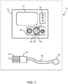
- Figure 1 shows a patient monitoring system 10, comprising a patient monitor 20, a patient sensor 30 and a measurement cable 40 coupled to the patient sensor, for removable connection to the patient monitor at an end of the cable.
- the patient sensor is for example for vital signs measurement. This may for example include ECG monitoring, respiration monitoring, temperature monitoring and others.
- the patient sensor can be also a cable trunk to which a sensing element of the patient sensor can be coupled to.
- the patient sensor (30) can be an ECG trunk, to which a variety of ECG leads can be connected to.
- An electrical connector is provided between the end of the measurement cable 40 and the patient monitor 20.
- the electrical connector comprises a male part 50 and a female part 60.
- the measurement cable 40 is terminated with the male part and the patient monitor has the female part.
- the electrical connector could be the other way around.
- the male part comprises a set of pins 52 and an annular shroud 54 surrounding the set of pins.
- the female part 60 comprises a set of pin openings 62 extending into a connector body 63, each pin opening 62 for receiving a respective pin 52 of the set of pins, and a recess 64 surrounding the set of pin openings for receiving the annular shroud 54.
- the invention provides an annular seal between a surface of the shroud 54 and a surface of the recess 64.
- This patient monitoring system thus uses a seal between a shroud of a male connector part and a recess of a female connector part. In this way, a single seal is used which surrounds the connector pins. This enables the patient monitoring system to be used in damp or wet situations such as in rescue helicopters, ambulances, military vehicles etc.
- Figure 2 shows a first example of the electrical connector.
- the male part 50 is part of, and at the end of, the measurement cable 40 and the female part 60 is part of the patient monitor 20.
- the annular shroud 54 extends beyond the ends of the pins 52 so protects the pins from damage as well as providing an alignment feature between the male and female parts of the connector.
- the annular shroud comprises a closed ring which may be circular or non-circular. It has a radially outwardly facing outermost lateral surface 70 and a radially inwardly facing innermost lateral surface 72.
- the recess 64 has a corresponding shape.
- the recess 64 has an outermost inwardly facing lateral surface 66 and an innermost outwardly facing lateral surface 68.
- the annular seal 80 extends between the radially outwardly facing lateral surface 70 of the shroud and the radially inwardly facing lateral surface 66 of the recess 64. Thus, the annular seal is positioned around the outside of the shroud.
- the seal could however be positioned between the innermost outwardly facing lateral surface 68 of the recess and the radially inwardly facing lateral surface 72 of the shroud. Sealing this passage similarly provides protection of the electrical contacts from water ingress. However, the seal in Figure 2 is positioned at the first possible point of water ingress.
- the annular seal is attached to the outermost inwardly facing lateral surface 66 of the recess, and hence is fixed to the patient monitor.
- a conventional sensor cable may be used.
- a modified patient monitor may be used with standard sensor cables and then provide protection against water ingress.
- the invention also provides such a modified patient monitor.
- the modified patient monitor may either have:
- the annular seal 80 is shown in Figure 2 as having a radially protruding lip.
- the lip preferably compresses radially when the male part is received in the female part, thus providing a seal.
- the lip for example faces in the direction of the bottom of the recess so that it is bent downwardly upon insertion of the male part of the connector.
- Figure 3 shows a second example of the electrical connector.
- the male part 50 is again part of the measurement cable 40 and the female part is part 60 of the patient monitor 20.
- the annular seal is attached to the radially outwardly facing lateral surface 70 and hence is fixed to the male connector part at the end of the sensor cable.
- a conventional patient monitor may be used.
- a modified sensor cable may be used with a standard patient monitor to provide protection against water ingress.
- the invention also provides such a modified sensor cable having a patient sensor, a measurement cable coupled to the patient sensor and a connector at an end of the measurement cable.
- the connector may comprise:
- the annular seal is shown in Figure 3 as having a pair of radially protruding lips, i.e. two annular seals in series.
- the lips again compress radially when the male part is received in the female part, thus providing a seal.
- the lips for example again face in the direction of the bottom of the recess so that they are bent downwardly upon insertion of the male part of the connector.
- the annular seal may be a silicone seal or an Ethylene Propylene Diene Monomer, EPDM, seal.
- EPDM Ethylene Propylene Diene Monomer
- a VMQ silicone seal may for example be used.
- the annular seal may be integrally formed using 2K molding. Thus it may be an integral part of the component to which it is attached. This prevents any risk of detachment and loss of the seal.
- the annular seal for example does not need to sit in a recess but is formed integrally with the surface from which it projects.
- the seal may instead be glued to the part to which it is to be connected. It may for example be located by a bezel, to which it is glued or welded.
- Figure 4 shows an example of a male connector part 50, in this example shown at the end of a measurement cable 40, more clearly.
- the seal 80 is on the inner surface of the shroud 54, surrounding the pins 52.
- the connector part is circular, but the overall shape of the male connector 50 is non-circular so that it has only one possible angular orientation with which it can fit to the female connector part.
- Figure 5 shows an example of a female connector part, for example for the patient monitor, for mating with the male connector part of Figure 4 . It shows the seal 80 around the projecting body 63.
- the recess 64 has a non-constant width so that it can accommodate the outer shape of the male part.
- a locking feature is shown schematically as 65, which may click the male connector in place to prevent accidental decoupling of the connector.
- the seal 80 will typically be in only one of the male connector part and the female connector part, but there could be seals in both, for example with the seal of the female connector part at a deeper location (i.e. further towards the bottom of the recess 64) than the seal of the male connector part, so they they do not interfere with each other.
- Figure 6 shows three examples of possible seal shapes and show the seal as an integral part of one of the two connector parts.
- the arrows shows the direction of movement of the connector part carrying the seal assuming it is part of the measurement cable, but equally the seal may be static and the other connector part may move.
Priority Applications (6)
| Application Number | Priority Date | Filing Date | Title |
|---|---|---|---|
| EP20154221.4A EP3859901A1 (de) | 2020-01-29 | 2020-01-29 | Patientenüberwachungssystem |
| EP21701444.8A EP4097804B1 (de) | 2020-01-29 | 2021-01-20 | Patientenüberwachungssystem |
| JP2022542733A JP2023512172A (ja) | 2020-01-29 | 2021-01-20 | 患者モニタリングシステム |
| CN202180011058.4A CN115023864A (zh) | 2020-01-29 | 2021-01-20 | 患者监护系统 |
| PCT/EP2021/051093 WO2021151729A1 (en) | 2020-01-29 | 2021-01-20 | Patient monitoring system |
| US17/795,079 US20230081255A1 (en) | 2020-01-29 | 2021-01-20 | Patient monitoring system |
Applications Claiming Priority (1)
| Application Number | Priority Date | Filing Date | Title |
|---|---|---|---|
| EP20154221.4A EP3859901A1 (de) | 2020-01-29 | 2020-01-29 | Patientenüberwachungssystem |
Publications (1)
| Publication Number | Publication Date |
|---|---|
| EP3859901A1 true EP3859901A1 (de) | 2021-08-04 |
Family
ID=69375289
Family Applications (2)
| Application Number | Title | Priority Date | Filing Date |
|---|---|---|---|
| EP20154221.4A Withdrawn EP3859901A1 (de) | 2020-01-29 | 2020-01-29 | Patientenüberwachungssystem |
| EP21701444.8A Active EP4097804B1 (de) | 2020-01-29 | 2021-01-20 | Patientenüberwachungssystem |
Family Applications After (1)
| Application Number | Title | Priority Date | Filing Date |
|---|---|---|---|
| EP21701444.8A Active EP4097804B1 (de) | 2020-01-29 | 2021-01-20 | Patientenüberwachungssystem |
Country Status (5)
| Country | Link |
|---|---|
| US (1) | US20230081255A1 (de) |
| EP (2) | EP3859901A1 (de) |
| JP (1) | JP2023512172A (de) |
| CN (1) | CN115023864A (de) |
| WO (1) | WO2021151729A1 (de) |
Citations (4)
| Publication number | Priority date | Publication date | Assignee | Title |
|---|---|---|---|---|
| US20040077203A1 (en) * | 2002-10-18 | 2004-04-22 | Dewitt Donald E. | Sealed IEC electrical connector assembly |
| US20190058281A1 (en) * | 2017-08-15 | 2019-02-21 | Masimo Corporation | Water resistant connector for noninvasive patient monitor |
| US20190067858A1 (en) * | 2017-08-23 | 2019-02-28 | Haes, Llc | Bayonet connector |
| WO2019193212A1 (en) * | 2018-04-06 | 2019-10-10 | Drägerwerk AG & Co. KGaA | Modular patient monitoring medical device and connector |
Family Cites Families (1)
| Publication number | Priority date | Publication date | Assignee | Title |
|---|---|---|---|---|
| WO2004075349A2 (en) * | 2003-02-18 | 2004-09-02 | Medconx, Inc. | Male medical device electrical connector with engineered friction fit |
-
2020
- 2020-01-29 EP EP20154221.4A patent/EP3859901A1/de not_active Withdrawn
-
2021
- 2021-01-20 CN CN202180011058.4A patent/CN115023864A/zh active Pending
- 2021-01-20 EP EP21701444.8A patent/EP4097804B1/de active Active
- 2021-01-20 JP JP2022542733A patent/JP2023512172A/ja active Pending
- 2021-01-20 WO PCT/EP2021/051093 patent/WO2021151729A1/en unknown
- 2021-01-20 US US17/795,079 patent/US20230081255A1/en active Pending
Patent Citations (4)
| Publication number | Priority date | Publication date | Assignee | Title |
|---|---|---|---|---|
| US20040077203A1 (en) * | 2002-10-18 | 2004-04-22 | Dewitt Donald E. | Sealed IEC electrical connector assembly |
| US20190058281A1 (en) * | 2017-08-15 | 2019-02-21 | Masimo Corporation | Water resistant connector for noninvasive patient monitor |
| US20190067858A1 (en) * | 2017-08-23 | 2019-02-28 | Haes, Llc | Bayonet connector |
| WO2019193212A1 (en) * | 2018-04-06 | 2019-10-10 | Drägerwerk AG & Co. KGaA | Modular patient monitoring medical device and connector |
Also Published As
| Publication number | Publication date |
|---|---|
| EP4097804B1 (de) | 2024-03-27 |
| EP4097804A1 (de) | 2022-12-07 |
| US20230081255A1 (en) | 2023-03-16 |
| CN115023864A (zh) | 2022-09-06 |
| JP2023512172A (ja) | 2023-03-24 |
| WO2021151729A1 (en) | 2021-08-05 |
Similar Documents
| Publication | Publication Date | Title |
|---|---|---|
| US5509822A (en) | ECG monitor system | |
| US5197898A (en) | Multi-contact electrical connector with one-piece seal | |
| US20080009198A1 (en) | Flexible connector for implantable wiring harness | |
| US11374351B2 (en) | Multipolar connector | |
| US6782758B2 (en) | Hermetic pressure transducer | |
| US6715357B2 (en) | Hermetic pressure transducer | |
| US6375487B1 (en) | Removable connector cable having bend and strain relief with integral seal | |
| JP2017042387A (ja) | ウェアラブル電極および生体信号モニタシステム | |
| EP3859901A1 (de) | Patientenüberwachungssystem | |
| CN111095685A (zh) | 医学成像设备连接器组件 | |
| CN110584676A (zh) | 传感装置 | |
| US6672170B1 (en) | Hermetic pressure transducer | |
| GB1274777A (en) | Electrical connector with an accordian sealing member | |
| US4828509A (en) | Sealed housing system for modular type connectors | |
| US20190285178A1 (en) | Pressure sensor unit with circular gasket | |
| US8926373B2 (en) | Male connector, female connector and connector arrangement | |
| JPH0317422Y2 (de) | ||
| US20230068002A1 (en) | Highly integrated analyte detection device | |
| JPH118009A (ja) | 防水コネクタ及びそれを組み込んだ電子機器ケーシング並びに防水コネクタを組み込んだ電子機器ケーシングと相手方防水コネクタとの組合せ | |
| JP2541481Y2 (ja) | 密閉コネクター | |
| EP1382953A2 (de) | Hermetischer Druckwandler | |
| CN111494744B (zh) | 一种检测单元集成盒及管道 | |
| CN215299636U (zh) | 连接器壳体组件和连接器 | |
| US20100317227A1 (en) | Electrical connector assembly with improved sealing structure | |
| CN216773640U (zh) | 一种单卡扣防水连接器 |
Legal Events
| Date | Code | Title | Description |
|---|---|---|---|
| PUAI | Public reference made under article 153(3) epc to a published international application that has entered the european phase |
Free format text: ORIGINAL CODE: 0009012 |
|
| STAA | Information on the status of an ep patent application or granted ep patent |
Free format text: STATUS: THE APPLICATION HAS BEEN PUBLISHED |
|
| AK | Designated contracting states |
Kind code of ref document: A1 Designated state(s): AL AT BE BG CH CY CZ DE DK EE ES FI FR GB GR HR HU IE IS IT LI LT LU LV MC MK MT NL NO PL PT RO RS SE SI SK SM TR |
|
| STAA | Information on the status of an ep patent application or granted ep patent |
Free format text: STATUS: THE APPLICATION IS DEEMED TO BE WITHDRAWN |
|
| 18D | Application deemed to be withdrawn |
Effective date: 20220205 |