EP3859359A1 - Signal analysis method and test system - Google Patents
Signal analysis method and test system Download PDFInfo
- Publication number
- EP3859359A1 EP3859359A1 EP20154120.8A EP20154120A EP3859359A1 EP 3859359 A1 EP3859359 A1 EP 3859359A1 EP 20154120 A EP20154120 A EP 20154120A EP 3859359 A1 EP3859359 A1 EP 3859359A1
- Authority
- EP
- European Patent Office
- Prior art keywords
- device under
- under test
- artificial intelligence
- analysis method
- signal
- Prior art date
- Legal status (The legal status is an assumption and is not a legal conclusion. Google has not performed a legal analysis and makes no representation as to the accuracy of the status listed.)
- Granted
Links
Images

Classifications
-
- G—PHYSICS
- G01—MEASURING; TESTING
- G01R—MEASURING ELECTRIC VARIABLES; MEASURING MAGNETIC VARIABLES
- G01R31/00—Arrangements for testing electric properties; Arrangements for locating electric faults; Arrangements for electrical testing characterised by what is being tested not provided for elsewhere
- G01R31/28—Testing of electronic circuits, e.g. by signal tracer
-
- G—PHYSICS
- G06—COMPUTING OR CALCULATING; COUNTING
- G06F—ELECTRIC DIGITAL DATA PROCESSING
- G06F11/00—Error detection; Error correction; Monitoring
- G06F11/22—Detection or location of defective computer hardware by testing during standby operation or during idle time, e.g. start-up testing
- G06F11/2257—Detection or location of defective computer hardware by testing during standby operation or during idle time, e.g. start-up testing using expert systems
-
- G—PHYSICS
- G01—MEASURING; TESTING
- G01R—MEASURING ELECTRIC VARIABLES; MEASURING MAGNETIC VARIABLES
- G01R31/00—Arrangements for testing electric properties; Arrangements for locating electric faults; Arrangements for electrical testing characterised by what is being tested not provided for elsewhere
-
- G—PHYSICS
- G06—COMPUTING OR CALCULATING; COUNTING
- G06F—ELECTRIC DIGITAL DATA PROCESSING
- G06F1/00—Details not covered by groups G06F3/00 - G06F13/00 and G06F21/00
- G06F1/26—Power supply means, e.g. regulation thereof
- G06F1/28—Supervision thereof, e.g. detecting power-supply failure by out of limits supervision
-
- G—PHYSICS
- G06—COMPUTING OR CALCULATING; COUNTING
- G06N—COMPUTING ARRANGEMENTS BASED ON SPECIFIC COMPUTATIONAL MODELS
- G06N20/00—Machine learning
-
- G—PHYSICS
- G06—COMPUTING OR CALCULATING; COUNTING
- G06N—COMPUTING ARRANGEMENTS BASED ON SPECIFIC COMPUTATIONAL MODELS
- G06N3/00—Computing arrangements based on biological models
- G06N3/02—Neural networks
- G06N3/04—Architecture, e.g. interconnection topology
- G06N3/0499—Feedforward networks
-
- G—PHYSICS
- G06—COMPUTING OR CALCULATING; COUNTING
- G06N—COMPUTING ARRANGEMENTS BASED ON SPECIFIC COMPUTATIONAL MODELS
- G06N3/00—Computing arrangements based on biological models
- G06N3/02—Neural networks
- G06N3/08—Learning methods
- G06N3/09—Supervised learning
-
- G—PHYSICS
- G06—COMPUTING OR CALCULATING; COUNTING
- G06N—COMPUTING ARRANGEMENTS BASED ON SPECIFIC COMPUTATIONAL MODELS
- G06N3/00—Computing arrangements based on biological models
- G06N3/02—Neural networks
- G06N3/08—Learning methods
- G06N3/092—Reinforcement learning
-
- H—ELECTRICITY
- H04—ELECTRIC COMMUNICATION TECHNIQUE
- H04B—TRANSMISSION
- H04B17/00—Monitoring; Testing
- H04B17/10—Monitoring; Testing of transmitters
- H04B17/15—Performance testing
- H04B17/17—Detection of non-compliance or faulty performance, e.g. response deviations
-
- G—PHYSICS
- G06—COMPUTING OR CALCULATING; COUNTING
- G06N—COMPUTING ARRANGEMENTS BASED ON SPECIFIC COMPUTATIONAL MODELS
- G06N3/00—Computing arrangements based on biological models
- G06N3/02—Neural networks
- G06N3/08—Learning methods
Definitions
- the invention generally relates to a signal analysis method of analyzing a performance of a device under test.
- the invention further relates to a test system for analyzing a performance of a device under test as well as to a computer program.
- RF devices used for wireless transmission of information and data are typically tested by a separately formed test and measurement device during or after production of the RF device.
- the device under test may transmit a test signal for testing purposes wherein the test signal is received by the test and measurement device for analyzing purposes.
- a testing system is usually complex, and a highly trained operator is necessary in order to obtain correct testing results.
- the object of the invention is to provide a signal analysis method as well as a testing system that are easier to operate.
- the problem is solved by a signal analysis method of analyzing a performance of a device under test.
- the method comprises the following steps: A digitized input signal is obtained, wherein the digitized input signal is associated with the device under test. At least one characteristic quantity is determined via an artificial intelligence module.
- the artificial intelligence module comprises at least one computing parameter. The at least one characteristic quantity is determined based on the digitized input signal and based on the at least one computing parameter. The at least one characteristic quantity is indicative of at least one performance property of the device under test.
- the term "the digitized input signal is associated with the device under test” comprises both the possibility that the digitized input signal is a digitized version of the output signal of the device under test as well as the possibility that the output signal of the device under test is received via one or more antennas and that the received signal is digitized, particularly by a test system for analyzing a performance of the device under test.
- the at least one characteristic quantity may comprise information on certain aspects of the performance of the device under test and/or about particular faults and errors in the performance of the device under test.
- the at least one characteristic quantity may have any suitable form.
- it may comprise a scalar, a vector, a matrix and/or a tensor.
- the at least one characteristic quantity i.e. information on the performance of the device under test
- the artificial intelligence module determines in a fully automatic way by the artificial intelligence module based directly on the digitized input signal. No further processing of the digitized input signal is required, which may be complicated as parameters and operational modes of the corresponding processing devices would have to be set, which usually can only be done by an expert in the field, yielding a restricted user-friendliness.
- a user friendly and easy way of testing the performance of the device under test is provided.
- the device under test is categorized into at least one of at least two different performance categories based on the at least one characteristic quantity determined.
- the device under test may be categorized into the category "test passed" or "test not passed”.
- categories there may be more different categories, particularly categories associated with particular errors or defects in the performance of the device under test. This way, the errors and defects can be comprehended in an easier way by a user, and appropriate consequences for the production of the device under test may be taken.
- a control unit controls the device under test to enter a predetermined operation mode and/or a sequence of predetermined operation modes, namely at least one predetermined operation mode.
- the predetermined operation mode corresponds to a certain sending mode of the device under test.
- the device under test generates an electromagnetic signal in a predetermined way in the predetermined operation mode or in the sequence of predetermined operation modes.
- the predetermined operation mode or rather the sequence of predetermined operation modes may be associated with a predefined test procedure that is suitable for the particular device under test.
- the predefined test procedure may be a normed test procedure.
- control unit controls the artificial intelligence module to adapt the at least one computing parameter based on the predetermined operation mode of the device under test.
- the at least one computing parameter is adapted to suit the particular operation mode of the device under test and/or the particular sequence of operation modes of the device under test.
- the at least one computing parameter is adapted fully automatically, without a need of manual intervention by a human operator.
- control unit provides a communication between the artificial intelligence module and the device under test such that the computing parameter can be adapted in dependency of the current or intended operation mode of the device under test. This simplifies and improves the determination of the characteristic quantity by means of the artificial intelligence module significantly.
- the power supply unit provides the device under test with power, wherein the power supply unit provides usage information on a power consumption of the device under test, a current consumption of the device under test and/or a voltage applied to the device under test, and wherein the usage information is forwarded to the artificial intelligence module.
- the power supply unit provides usage information on a power consumption of the device under test, a current consumption of the device under test and/or a voltage applied to the device under test, and wherein the usage information is forwarded to the artificial intelligence module.
- the artificial intelligence module determines the at least one characteristic parameter based on the usage information. Accordingly, the at least one characteristic parameter is determined based on a broader set of data, and the quality of the performance analysis by the artificial intelligence module is enhanced.
- the artificial intelligence module may be a machine learning module that is trained to determine the at least one characteristic quantity, particularly wherein the artificial intelligence module comprises an artificial neural network.
- the artificial intelligence module is trained to determine the at least one characteristic parameter by a suitable machine learning technique, particularly by a suitable deep learning technique.
- training data comprises at least one reference characteristic quantity of the reference device under test and/or a training input signal that is associated with a reference device under test having known performance properties, and wherein the at least one computing parameter is adapted based on the training data.
- labelled and/or unlabelled training data is provided, wherein the training data at least comprises a training input signal that is associated with a reference device under test having known performance properties. If the training data is labelled, the training data may also comprise a reference characteristic quantity of the reference device under test.
- the at least one computing parameter is adapted via supervised learning, unsupervised learning and/or reinforcement learning.
- at least parts of the training may be performed based on feedback given by an expert in the field.
- the training may be performed fully automatic.
- the digitized signal may be a time domain signal, particularly wherein the digitized signal has a predefined duration.
- the digitized signal may also be a frequency domain signal, particularly wherein the digitized signal has a predefined bandwidth.
- the at least one computing parameter may be adapted based on the predefined duration and/or based on the predefined bandwidth.
- test system for analyzing a performance of a device under test.
- the test system comprises a data acquisition unit configured to obtain a digitized input signal.
- the test unit further comprises an artificial intelligence module comprising at least one computing parameter, and a control unit.
- the control unit is configured to cause the test system to perform the signal analysis method described above.
- the test system comprises the device under test.
- the test system comprises a power supply unit, wherein the power supply unit is configured to provide the device under test with power, and wherein the power supply unit is configured to provide usage information on a power consumption of the device under test, a current consumption of the device under test and/or a voltage applied to the device under test.
- the power supply unit is configured to provide usage information on a power consumption of the device under test, a current consumption of the device under test and/or a voltage applied to the device under test.
- the artificial intelligence module is established as software running on a computing device.
- the computing device may be established as at least one computer, at least one laptop, at least one server, at least one smartphone, at least one tablet and/or at least one other type of smart device.
- the computing device established by several computers and/or servers that form a cloud computing setup.
- a computer program comprising program code means being adapted to cause a test system, particularly the test system described above, to perform the signal analysis method described above if the computer program is executed on a processing unit of a control unit of the test system.
- program code means is understood to comprise computer-executable instructions in the form of program code and/or program code modules, in compiled and/or uncompiled form.
- the program code means may be provided in an arbitrary programming language and/or in machine language.
- Figure 1 schematically shows a test system 10 comprising a device under test 12 and a testing assembly 14.
- the testing assembly 14 comprises a data acquisition unit 16, a computing device 17 with an artificial intelligence module 18, and a control unit 20.
- the device under test 12 is a radio frequency (RF) device that is used for wireless transmission of information and data.
- RF radio frequency
- the device under test 12 is a mobile communication device, for example a mobile, a tablet or a smartphone.
- the data acquisition unit 16, the computing device 17 with the artificial intelligence module 18, and/or the control unit 20 may be integrated into a common measurement device, for example into an oscilloscope, a vector network analyzer etc. Hence, a housing may be provided that encompasses the respective components. Alternatively, one or more of the data acquisition unit 16, the computing device 17, and/or the control unit 20 may be established separately, particularly self-contained.
- the data acquisition unit 16 comprises an antenna 22, a local oscillator 24, a mixer 26, a filter 28, and an analog to digital converter (ADC) 30.
- ADC analog to digital converter
- the computing device 17 may be established as at least one computer, at least one laptop, at least one server, at least one smartphone, at least one tablet and/or at least one other type of smart device. Particularly, the computing device 17 may be established via a cloud computing setup.
- the artificial intelligence module 18 is established as a software module that is saved on a data memory of the computing device 17, and that can be executed on a processing unit of the computing device 17, particularly on a central processing unit and/or on a graphics processing unit of the computing device 17.
- the artificial intelligence module 18 is a machine learning module.
- the artificial intelligence module 18 comprises an artificial neural network.
- the control unit 20 may be established as a computer, a laptop, a server, a smart phone, a tablet and/or as any other type of smart device.
- the computing device 17, and thus also the artificial intelligence module 18 is connected to the data acquisition unit 16 downstream of the data acquisition unit 16 in a signal transmitting manner.
- downstream and upstream are used to indicate the flow directions of data, signals and/or information within the test system 10, wherein the flow direction is from the upstream component to the downstream component.
- the control unit 20 is connected to each of the data acquisition unit 16 and to the computing device 17, and thus also to the artificial intelligence module 18 in a signal transmitting manner.
- FIG 2 shows a second variant of the test system 10, wherein the only difference to the variant shown in Figure 1 is that an additional power supply unit 32 is provided.
- the power supply unit 32 is configured to supply the device under test 12 with power.
- the power supply unit 32 is connected to the computing device 17, and thus to the artificial intelligence module 18 in a signal transmitting manner.
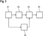
- both the first and the second variant of the test system 10 described above are configured to perform a signal analysis method of analyzing a performance of the device under test 12. This signal analysis method will be described in the following with reference to Figure 3 .
- a computer program is executed on the control unit 20, particularly on a processing unit of the control unit 20, wherein the computer program comprises program code means that are adapted to cause the test system 10 to perform the signal analysis method described below.
- the control unit 20 controls the device under test 12 to enter a predetermined operation mode and/or a sequence of predetermined operation modes (step S1).
- the predetermined operation mode corresponds to the sending mode of the device under test 12.
- the device under test 12 generates an electromagnetic signal in a predetermined way in the predetermined operation mode or in the sequence of predetermined operation modes.
- the predetermined operation mode or rather the sequence of predetermined operation modes may be associated with a predefined test procedure that is suitable for the particular device under test 12.
- the predefined test procedure may be a normed test procedure.
- the device under test 12 generates the electromagnetic signals in the form of electromagnetic waves radiated over the air.
- the electromagnetic signal may, depending on the type of the device under test 12, also be generated and transmitted via a wire-based connection.
- the electromagnetic signals generated by the device under test 12 are then received and digitized by the data acquisition unit 16, thereby obtaining a digitized input signal (step S2), wherein the digitized input signal may be associated with time domain or with frequency domain.
- the electromagnetic waves generated by the device under test 12 are received via the antenna 22 and are mixed down via the mixer 26 based on an oscillator signal from the local oscillator 24.
- the down-mixed signal is then filtered via the filter 28 and digitized by the analog to digital converter 30.
- the data acquisition unit 16 may comprise a memory for storing the digitized input signal.
- the digitized input signal is then forwarded to the computing device 17, and thus also to the artificial intelligence module 18.
- the computing device 17 may comprise a memory for storing the digitized input signal, particularly a buffer memory.
- the power supply unit 32 may generate usage information, wherein the usage information comprises information on a power consumption of the device under test 12, the current consumption of the device under test 12 and/or a voltage applied to the device under test 12. A signal containing this usage information may be forwarded to the artificial intelligence module 18.
- the artificial intelligence module 18 determines at least one characteristic quantity based on at least one computing parameter of the artificial intelligence module 18, based on the digitized input signal and, optionally, based on the usage information (step S3).
- computing parameter is a collective term representing computational parameters that are employed by the artificial intelligence module 18 in order to determine the at least one characteristic quantity.
- the at least one computing parameter comprises weighting factors of the individual neurons of the artificial neural network.
- the at least one characteristic quantity is indicative of one or several performance properties of the device under test 12. More precisely, the at least one characteristic quantity may comprise information on certain aspects of the performance of the device under test 12 and/or about particular faults and errors in the performance of the device under test 12.
- the at least one characteristic quantity may have any suitable form, for example it may comprise a scalar, a vector, a matrix and/or a tensor.
- the at least one characteristic quantity may comprise information on beamforming properties, a responsiveness, a power consumption, a current consumption, an effectiveness, and/or any other property of the device under test 12 that is suitable for assessing the performance of the device under test 12.
- the artificial intelligence module 18, particularly the artificial neural network is trained to determine the characteristic quantity based on digitized input signal and, optionally, based on the usage information.
- the training of the artificial intelligence module 18 may be done in any suitable fashion, i.e. with any suitable machine learning technique.
- the training procedure may comprise supervised learning, unsupervised learning and/or reinforcement learning.
- labelled and/or unlabelled training data is provided, wherein the training data at least comprises a training input signal that is associated with a reference device under test having known performance properties.
- the training data may also comprise a reference characteristic quantity of the reference device under test.
- the reference characteristic quantity may be obtained by a (onetime) analysis of the performance of the reference device under test by a skilled operator using a test system known from the state-of-the-art.
- the provided training data is processed via the artificial intelligence module 18, such that a provisional characteristic quantity is obtained.
- the provisional characteristic quantity may then be compared to the reference characteristic quantity and/or may be checked by a human operator.
- feedback is given to the artificial intelligence module and the at least one computing parameter is adapted via suitable machine learning techniques.
- the device under test 12 is categorized into at least one of at least two different performance categories (step S4), particularly by the artificial intelligence module 18.
- the device under test 12 may be categorized into the category "test passed” or "test not passed”.
- control unit 20 may also control the artificial intelligence module 18 to adapt the at least one computing parameter based on the predetermined operation mode of the device under test 12 and/or the predetermined sequence of operation modes of the device under test 12.
- the at least one computing parameter may be adapted to suit the particular operation mode of the device under test 12 or the particular sequence of operation modes of the device under test 12.
- each set of computing parameters may be stored in the computing device 17 and/or in the artificial intelligence module 18, wherein each set of computing parameters may be associated with one or more particular operation modes of the device under test 12.
- test system 10 and the signal analysis methods described above provide an easy way of testing the device under test 12, because all relevant evaluations are automatically performed by the artificial intelligence module 18 and do not require substantive knowledge in the field.
Landscapes
- Engineering & Computer Science (AREA)
- Theoretical Computer Science (AREA)
- Physics & Mathematics (AREA)
- General Engineering & Computer Science (AREA)
- General Physics & Mathematics (AREA)
- Software Systems (AREA)
- Evolutionary Computation (AREA)
- Mathematical Physics (AREA)
- Data Mining & Analysis (AREA)
- Computing Systems (AREA)
- Artificial Intelligence (AREA)
- Computational Linguistics (AREA)
- Biophysics (AREA)
- Molecular Biology (AREA)
- General Health & Medical Sciences (AREA)
- Biomedical Technology (AREA)
- Life Sciences & Earth Sciences (AREA)
- Health & Medical Sciences (AREA)
- Quality & Reliability (AREA)
- Computer Hardware Design (AREA)
- Computer Vision & Pattern Recognition (AREA)
- Medical Informatics (AREA)
- Signal Processing (AREA)
- Computer Networks & Wireless Communication (AREA)
- Electromagnetism (AREA)
- Testing Electric Properties And Detecting Electric Faults (AREA)
- Tests Of Electronic Circuits (AREA)
Abstract
Description
- The invention generally relates to a signal analysis method of analyzing a performance of a device under test. The invention further relates to a test system for analyzing a performance of a device under test as well as to a computer program.
- In the state of the art, RF devices used for wireless transmission of information and data, for example mobile communication devices, are typically tested by a separately formed test and measurement device during or after production of the RF device.
- The device under test may transmit a test signal for testing purposes wherein the test signal is received by the test and measurement device for analyzing purposes. However, such a testing system is usually complex, and a highly trained operator is necessary in order to obtain correct testing results.
- Accordingly, the object of the invention is to provide a signal analysis method as well as a testing system that are easier to operate.
- According to the invention, the problem is solved by a signal analysis method of analyzing a performance of a device under test. The method comprises the following steps: A digitized input signal is obtained, wherein the digitized input signal is associated with the device under test. At least one characteristic quantity is determined via an artificial intelligence module. The artificial intelligence module comprises at least one computing parameter. The at least one characteristic quantity is determined based on the digitized input signal and based on the at least one computing parameter. The at least one characteristic quantity is indicative of at least one performance property of the device under test.
- The term "the digitized input signal is associated with the device under test" comprises both the possibility that the digitized input signal is a digitized version of the output signal of the device under test as well as the possibility that the output signal of the device under test is received via one or more antennas and that the received signal is digitized, particularly by a test system for analyzing a performance of the device under test.
- The at least one characteristic quantity may comprise information on certain aspects of the performance of the device under test and/or about particular faults and errors in the performance of the device under test.
- The at least one characteristic quantity may have any suitable form. For example, it may comprise a scalar, a vector, a matrix and/or a tensor.
- In other words, the at least one characteristic quantity, i.e. information on the performance of the device under test, is determined in a fully automatic way by the artificial intelligence module based directly on the digitized input signal. No further processing of the digitized input signal is required, which may be complicated as parameters and operational modes of the corresponding processing devices would have to be set, which usually can only be done by an expert in the field, yielding a restricted user-friendliness. Thus, a user friendly and easy way of testing the performance of the device under test is provided.
- According to an aspect of the invention, the device under test is categorized into at least one of at least two different performance categories based on the at least one characteristic quantity determined. For example, the device under test may be categorized into the category "test passed" or "test not passed". Of course, there may be more different categories, particularly categories associated with particular errors or defects in the performance of the device under test. This way, the errors and defects can be comprehended in an easier way by a user, and appropriate consequences for the production of the device under test may be taken.
- According to another aspect of the present disclosure, a control unit is provided, wherein the control unit controls the device under test to enter a predetermined operation mode and/or a sequence of predetermined operation modes, namely at least one predetermined operation mode. The predetermined operation mode corresponds to a certain sending mode of the device under test. Thus, the device under test generates an electromagnetic signal in a predetermined way in the predetermined operation mode or in the sequence of predetermined operation modes.
- The predetermined operation mode or rather the sequence of predetermined operation modes may be associated with a predefined test procedure that is suitable for the particular device under test. The predefined test procedure may be a normed test procedure.
- In an embodiment of the invention, the control unit controls the artificial intelligence module to adapt the at least one computing parameter based on the predetermined operation mode of the device under test. In other words, the at least one computing parameter is adapted to suit the particular operation mode of the device under test and/or the particular sequence of operation modes of the device under test. The at least one computing parameter is adapted fully automatically, without a need of manual intervention by a human operator.
- In other words, the control unit provides a communication between the artificial intelligence module and the device under test such that the computing parameter can be adapted in dependency of the current or intended operation mode of the device under test. This simplifies and improves the determination of the characteristic quantity by means of the artificial intelligence module significantly.
- According to a further embodiment of the present invention, the power supply unit provides the device under test with power, wherein the power supply unit provides usage information on a power consumption of the device under test, a current consumption of the device under test and/or a voltage applied to the device under test, and wherein the usage information is forwarded to the artificial intelligence module. Thus, additional information on performance properties of the device under test is provided, which may be utilized by the artificial intelligence module.
- Particularly, the artificial intelligence module determines the at least one characteristic parameter based on the usage information. Accordingly, the at least one characteristic parameter is determined based on a broader set of data, and the quality of the performance analysis by the artificial intelligence module is enhanced.
- The artificial intelligence module may be a machine learning module that is trained to determine the at least one characteristic quantity, particularly wherein the artificial intelligence module comprises an artificial neural network. In other words, the artificial intelligence module is trained to determine the at least one characteristic parameter by a suitable machine learning technique, particularly by a suitable deep learning technique.
- According to an aspect of the present invention, training data is provided, wherein the training data comprises at least one reference characteristic quantity of the reference device under test and/or a training input signal that is associated with a reference device under test having known performance properties, and wherein the at least one computing parameter is adapted based on the training data. In other words, labelled and/or unlabelled training data is provided, wherein the training data at least comprises a training input signal that is associated with a reference device under test having known performance properties. If the training data is labelled, the training data may also comprise a reference characteristic quantity of the reference device under test.
- According to another aspect of the present invention, the at least one computing parameter is adapted via supervised learning, unsupervised learning and/or reinforcement learning. Thus, at least parts of the training may be performed based on feedback given by an expert in the field. Alternatively or additionally, the training may be performed fully automatic.
- The digitized signal may be a time domain signal, particularly wherein the digitized signal has a predefined duration. The digitized signal may also be a frequency domain signal, particularly wherein the digitized signal has a predefined bandwidth. The at least one computing parameter may be adapted based on the predefined duration and/or based on the predefined bandwidth.
- According to the invention, the problem further is solved by a test system for analyzing a performance of a device under test. The test system comprises a data acquisition unit configured to obtain a digitized input signal. The test unit further comprises an artificial intelligence module comprising at least one computing parameter, and a control unit. The control unit is configured to cause the test system to perform the signal analysis method described above.
- Regarding the advantages and further properties of the test system, reference is made to the explanations given above regarding the signal analysis, which also hold for the test system and vice versa.
- Particularly, the test system comprises the device under test.
- In an embodiment of the invention, the test system comprises a power supply unit, wherein the power supply unit is configured to provide the device under test with power, and wherein the power supply unit is configured to provide usage information on a power consumption of the device under test, a current consumption of the device under test and/or a voltage applied to the device under test. Thus, additional information on performance properties of the device under test are provided and may be utilized by the artificial intelligence module.
- According to a further embodiment of the present disclosure, the artificial intelligence module is established as software running on a computing device. The computing device may be established as at least one computer, at least one laptop, at least one server, at least one smartphone, at least one tablet and/or at least one other type of smart device. Particularly, the computing device established by several computers and/or servers that form a cloud computing setup.
- According to the invention, the problem further is solved by a computer program comprising program code means being adapted to cause a test system, particularly the test system described above, to perform the signal analysis method described above if the computer program is executed on a processing unit of a control unit of the test system.
- Therein and in the following, the term "program code means" is understood to comprise computer-executable instructions in the form of program code and/or program code modules, in compiled and/or uncompiled form. The program code means may be provided in an arbitrary programming language and/or in machine language.
- Regarding the further advantages and properties of the computer program, reference is made to the explanations given above regarding the signal analysis method and regarding the test system, which also hold for the computer program and vice versa.
- The foregoing aspects and many of the attendant advantages of the claimed subject matter will become more readily appreciated as the same become better understood by reference to the following detailed description, when taken in conjunction with the accompanying drawings, wherein:
-
Figure 1 schematically shows a test system according to a first variant of the invention; -
Figure 2 schematically shows a test system according to a second variant of the invention; and -
Figure 3 shows a block diagram of a signal analysis method according to the invention. - The detailed description set forth below in connection with the appended drawings, where like numerals reference like elements, is intended as a description of various embodiments of the disclosed subject matter and is not intended to represent the only embodiments. Each embodiment described in this disclosure is provided merely as an example or illustration and should not be construed as preferred or advantageous over other embodiments. The illustrative examples provided herein are not intended to be exhaustive or to limit the claimed subject matter to the precise forms disclosed. For the purposes of the present disclosure, the phrase "at least one of A, B, and C", for example, means (A), (B), (C), (A and B), (A and C), (B and C), or (A, B, and C), including all further possible permutations when greater than three elements are listed. In other words, the term "at least one of A and B" generally means "A and/or B", namely "A" alone, "B" alone or "A and B".
-
Figure 1 schematically shows atest system 10 comprising a device undertest 12 and atesting assembly 14. - The
testing assembly 14 comprises adata acquisition unit 16, acomputing device 17 with anartificial intelligence module 18, and acontrol unit 20. - The device under
test 12 is a radio frequency (RF) device that is used for wireless transmission of information and data. Particularly, the device undertest 12 is a mobile communication device, for example a mobile, a tablet or a smartphone. - However, it is to be understood that the explanations given in the following with regard to analyzing a signal generated by the device under
test 12 also apply to every kind of device undertest 12 that generates an electromagnetic signal that can be received and analyzed, be it by wireless transmission or by wire-based transmission of the electromagnetic signal. - The
data acquisition unit 16, thecomputing device 17 with theartificial intelligence module 18, and/or thecontrol unit 20 may be integrated into a common measurement device, for example into an oscilloscope, a vector network analyzer etc. Hence, a housing may be provided that encompasses the respective components. Alternatively, one or more of thedata acquisition unit 16, thecomputing device 17, and/or thecontrol unit 20 may be established separately, particularly self-contained. - The
data acquisition unit 16 comprises anantenna 22, alocal oscillator 24, amixer 26, afilter 28, and an analog to digital converter (ADC) 30. - The
computing device 17 may be established as at least one computer, at least one laptop, at least one server, at least one smartphone, at least one tablet and/or at least one other type of smart device. Particularly, thecomputing device 17 may be established via a cloud computing setup. - The
artificial intelligence module 18 is established as a software module that is saved on a data memory of thecomputing device 17, and that can be executed on a processing unit of thecomputing device 17, particularly on a central processing unit and/or on a graphics processing unit of thecomputing device 17. - More precisely, the
artificial intelligence module 18 is a machine learning module. Particularly, theartificial intelligence module 18 comprises an artificial neural network. - The
control unit 20 may be established as a computer, a laptop, a server, a smart phone, a tablet and/or as any other type of smart device. - The
computing device 17, and thus also theartificial intelligence module 18 is connected to thedata acquisition unit 16 downstream of thedata acquisition unit 16 in a signal transmitting manner. - Therein and in the following, the terms "downstream" and "upstream" are used to indicate the flow directions of data, signals and/or information within the
test system 10, wherein the flow direction is from the upstream component to the downstream component. - The
control unit 20 is connected to each of thedata acquisition unit 16 and to thecomputing device 17, and thus also to theartificial intelligence module 18 in a signal transmitting manner. -
Figure 2 shows a second variant of thetest system 10, wherein the only difference to the variant shown inFigure 1 is that an additionalpower supply unit 32 is provided. - The
power supply unit 32 is configured to supply the device undertest 12 with power. - Further, the
power supply unit 32 is connected to thecomputing device 17, and thus to theartificial intelligence module 18 in a signal transmitting manner. - Generally speaking, both the first and the second variant of the
test system 10 described above are configured to perform a signal analysis method of analyzing a performance of the device undertest 12. This signal analysis method will be described in the following with reference toFigure 3 . - More precisely, a computer program is executed on the
control unit 20, particularly on a processing unit of thecontrol unit 20, wherein the computer program comprises program code means that are adapted to cause thetest system 10 to perform the signal analysis method described below. - The
control unit 20 controls the device undertest 12 to enter a predetermined operation mode and/or a sequence of predetermined operation modes (step S1). - Therein, the predetermined operation mode corresponds to the sending mode of the device under
test 12. In other words, the device undertest 12 generates an electromagnetic signal in a predetermined way in the predetermined operation mode or in the sequence of predetermined operation modes. - The predetermined operation mode or rather the sequence of predetermined operation modes may be associated with a predefined test procedure that is suitable for the particular device under
test 12. The predefined test procedure may be a normed test procedure. - In the example of
Figures 1 and 2 , the device undertest 12 generates the electromagnetic signals in the form of electromagnetic waves radiated over the air. However, as already mentioned above, the electromagnetic signal may, depending on the type of the device undertest 12, also be generated and transmitted via a wire-based connection. - The electromagnetic signals generated by the device under
test 12 are then received and digitized by thedata acquisition unit 16, thereby obtaining a digitized input signal (step S2), wherein the digitized input signal may be associated with time domain or with frequency domain. - More precisely, the electromagnetic waves generated by the device under
test 12 are received via theantenna 22 and are mixed down via themixer 26 based on an oscillator signal from thelocal oscillator 24. The down-mixed signal is then filtered via thefilter 28 and digitized by the analog todigital converter 30. - The
data acquisition unit 16 may comprise a memory for storing the digitized input signal. - The digitized input signal is then forwarded to the
computing device 17, and thus also to theartificial intelligence module 18. - The
computing device 17 may comprise a memory for storing the digitized input signal, particularly a buffer memory. - In the variant of
Figure 2 , thepower supply unit 32 may generate usage information, wherein the usage information comprises information on a power consumption of the device undertest 12, the current consumption of the device undertest 12 and/or a voltage applied to the device undertest 12. A signal containing this usage information may be forwarded to theartificial intelligence module 18. - The
artificial intelligence module 18 determines at least one characteristic quantity based on at least one computing parameter of theartificial intelligence module 18, based on the digitized input signal and, optionally, based on the usage information (step S3). - Therein, the term "computing parameter" is a collective term representing computational parameters that are employed by the
artificial intelligence module 18 in order to determine the at least one characteristic quantity. - In the case of the
artificial intelligence module 18 comprising the artificial neural network, the at least one computing parameter comprises weighting factors of the individual neurons of the artificial neural network. - The at least one characteristic quantity is indicative of one or several performance properties of the device under
test 12. More precisely, the at least one characteristic quantity may comprise information on certain aspects of the performance of the device undertest 12 and/or about particular faults and errors in the performance of the device undertest 12. - Therein, the at least one characteristic quantity may have any suitable form, for example it may comprise a scalar, a vector, a matrix and/or a tensor.
- For example, the at least one characteristic quantity may comprise information on beamforming properties, a responsiveness, a power consumption, a current consumption, an effectiveness, and/or any other property of the device under
test 12 that is suitable for assessing the performance of the device undertest 12. - Generally speaking, the
artificial intelligence module 18, particularly the artificial neural network, is trained to determine the characteristic quantity based on digitized input signal and, optionally, based on the usage information. - The training of the
artificial intelligence module 18 may be done in any suitable fashion, i.e. with any suitable machine learning technique. - The training procedure may comprise supervised learning, unsupervised learning and/or reinforcement learning.
- For example, labelled and/or unlabelled training data is provided, wherein the training data at least comprises a training input signal that is associated with a reference device under test having known performance properties.
- Additionally, if the training data is labelled, the training data may also comprise a reference characteristic quantity of the reference device under test.
- The reference characteristic quantity may be obtained by a (onetime) analysis of the performance of the reference device under test by a skilled operator using a test system known from the state-of-the-art.
- In order to train the
artificial intelligence module 18, the provided training data is processed via theartificial intelligence module 18, such that a provisional characteristic quantity is obtained. The provisional characteristic quantity may then be compared to the reference characteristic quantity and/or may be checked by a human operator. - Based on the comparison and or/based on the analysis by the human operator, feedback is given to the artificial intelligence module and the at least one computing parameter is adapted via suitable machine learning techniques.
- Based on the at least one characteristic quantity determined, the device under
test 12 is categorized into at least one of at least two different performance categories (step S4), particularly by theartificial intelligence module 18. - For example, the device under
test 12 may be categorized into the category "test passed" or "test not passed". - Of course, there may be more different categories, particularly categories associated with particular errors or defects in the performance of the device under
test 12. - As is indicated by the dashed arrows in
Figures 3 , thecontrol unit 20 may also control theartificial intelligence module 18 to adapt the at least one computing parameter based on the predetermined operation mode of the device undertest 12 and/or the predetermined sequence of operation modes of the device undertest 12. - In other words, the at least one computing parameter may be adapted to suit the particular operation mode of the device under
test 12 or the particular sequence of operation modes of the device undertest 12. - Accordingly, several sets of computing parameters may be stored in the
computing device 17 and/or in theartificial intelligence module 18, wherein each set of computing parameters may be associated with one or more particular operation modes of the device undertest 12. - Summarizing, the
test system 10 and the signal analysis methods described above provide an easy way of testing the device undertest 12, because all relevant evaluations are automatically performed by theartificial intelligence module 18 and do not require substantive knowledge in the field.
Claims (15)
- A signal analysis method of analyzing a performance of a device under test (12), wherein the method comprises the following steps:- obtaining a digitized input signal, wherein the digitized input signal is associated with the device under test (12), and- determining at least one characteristic quantity via an artificial intelligence module (18), wherein the artificial intelligence module (18) comprises at least one computing parameter, and wherein the at least one characteristic quantity is determined based on the digitized input signal and based on the at least one computing parameter,wherein the at least one characteristic quantity is indicative of at least one performance property of the device under test (12).
- The signal analysis method of claim 1, characterized in that the device under test (12) is categorized into at least one of at least two different performance categories based on the at least one characteristic quantity determined.
- The signal analysis method according to any one of the preceding claims, characterized in that a control unit (20) is provided, wherein the control unit (20) controls the device under test (12) to enter a predetermined operation mode and/or a sequence of predetermined operation modes.
- The signal analysis method according to claim 3, characterized in that the control unit (20) controls the artificial intelligence module (18) to adapt the at least one computing parameter based on the predetermined operation mode of the device under test (12).
- The signal analysis method according to any one of the preceding claims, characterized in that a power supply unit (32) is provided, wherein the power supply unit (32) provides the device under test (12) with power, wherein the power supply unit (32) provides usage information on a power consumption of the device under test (12), a current consumption of the device under test (12) and/or a voltage applied to the device under test (12), and wherein the usage information is forwarded to the artificial intelligence module (18).
- The signal analysis method according to claim 5, characterized in that the artificial intelligence module (18) determines the at least one characteristic parameter based on the usage information.
- The signal analysis method according to any one of the preceding claims, characterized in that the artificial intelligence module (18) is a machine learning module that is trained to determine the at least one characteristic quantity, particularly wherein the artificial intelligence module (18) comprises an artificial neural network.
- The signal analysis method according to any one of the preceding claims, characterized in that training data is provided, wherein the training data comprises at least one reference characteristic quantity of the reference device under test and/or a training input signal that is associated with a reference device under test having known performance properties, and wherein the at least one computing parameter is adapted based on the training data.
- The signal analysis method of claim 8, characterized in that the at least one computing parameter is adapted via supervised learning, unsupervised learning and/or reinforcement learning.
- The signal analysis method according to any one of the preceding claims, characterized in that the digitized signal is a time domain signal, particularly wherein the digitized signal has a predefined duration, and/or characterized in that the digitized signal is a frequency domain signal, particularly wherein the digitized signal has a predefined bandwidth.
- A test system for analyzing a performance of a device under test (12), comprising a data acquisition unit (16) configured to obtain a digitized input signal, an artificial intelligence module (18) comprising at least one computing parameter, and a control unit (20), wherein the control unit (20) is configured to cause the test system (10) to perform the signal analysis method according to any one of the preceding claims.
- The test system of claim 11, characterized in that the test system (10) comprises the device under test (12).
- The test system of claim 12, characterized in that the test system (10) comprises a power supply unit (32), wherein the power supply unit (32) is configured to provide the device under test (12) with power, and wherein the power supply unit (32) is configured to provide usage information on a power consumption of the device under test (12), a current consumption of the device under test (12) and/or a voltage applied to the device under test (12).
- The test system according to any one of the claims 11 to 13, characterized in that the artificial intelligence module (18) is established as software running on a computing device (17).
- A computer program comprising program code means being adapted to cause a test system, particularly the test system (10) of any one of the claims 11 to 14, to perform the signal analysis method according to any one of the claims 1 to 10 if the computer program is executed on a processing unit of a control unit (20) of the test system.
Priority Applications (3)
| Application Number | Priority Date | Filing Date | Title |
|---|---|---|---|
| EP20154120.8A EP3859359B8 (en) | 2020-01-28 | 2020-01-28 | Signal analysis method and test system |
| US17/160,121 US11544164B2 (en) | 2020-01-28 | 2021-01-27 | Signal analysis method and test system |
| CN202110119633.4A CN113253011B (en) | 2020-01-28 | 2021-01-28 | Signal analysis method and test system |
Applications Claiming Priority (1)
| Application Number | Priority Date | Filing Date | Title |
|---|---|---|---|
| EP20154120.8A EP3859359B8 (en) | 2020-01-28 | 2020-01-28 | Signal analysis method and test system |
Publications (3)
| Publication Number | Publication Date |
|---|---|
| EP3859359A1 true EP3859359A1 (en) | 2021-08-04 |
| EP3859359B1 EP3859359B1 (en) | 2024-03-06 |
| EP3859359B8 EP3859359B8 (en) | 2024-04-10 |
Family
ID=69375235
Family Applications (1)
| Application Number | Title | Priority Date | Filing Date |
|---|---|---|---|
| EP20154120.8A Active EP3859359B8 (en) | 2020-01-28 | 2020-01-28 | Signal analysis method and test system |
Country Status (3)
| Country | Link |
|---|---|
| US (1) | US11544164B2 (en) |
| EP (1) | EP3859359B8 (en) |
| CN (1) | CN113253011B (en) |
Families Citing this family (2)
| Publication number | Priority date | Publication date | Assignee | Title |
|---|---|---|---|---|
| US20240235669A1 (en) * | 2021-03-24 | 2024-07-11 | Tektronix, Inc. | Systems and methods for tuning and measuring a device under test using machine learning |
| US12704895B2 (en) * | 2023-12-19 | 2026-08-11 | Qualcomm Incorporated | Power grid allocation in extended reality (XR) devices |
Citations (6)
| Publication number | Priority date | Publication date | Assignee | Title |
|---|---|---|---|---|
| US5115672A (en) * | 1991-02-11 | 1992-05-26 | Westinghouse Electric Corp. | System and method for valve monitoring using pipe-mounted ultrasonic transducers |
| EP2772862A1 (en) * | 2013-02-28 | 2014-09-03 | BlackBerry Limited | Electrical current estimation for electronic devices |
| US20150067422A1 (en) * | 2013-08-27 | 2015-03-05 | The United States Of America As Represented By The Secretary Of The Navy | Fusion of multiple modalities for determining a unique microelectronic device signature |
| US20150091594A1 (en) * | 2013-06-24 | 2015-04-02 | The United States Of America As Represented By The Secretary Of The Navy | Apparatus and Method for Integrated Circuit Forensics |
| US20180026737A1 (en) * | 2016-07-22 | 2018-01-25 | The Directv Group, Inc. | Determining ambient noise in a device under test electromagnetic compatibility test environment |
| US20190246299A1 (en) * | 2018-02-07 | 2019-08-08 | Rohde & Schwarz Gmbh & Co. Kg | Method and test system for mobile network testing as well as a network testing system |
Family Cites Families (34)
| Publication number | Priority date | Publication date | Assignee | Title |
|---|---|---|---|---|
| US5945948A (en) | 1996-09-03 | 1999-08-31 | Motorola, Inc. | Method and apparatus for location finding in a communication system |
| US6218910B1 (en) * | 1999-02-25 | 2001-04-17 | Formfactor, Inc. | High bandwidth passive integrated circuit tester probe card assembly |
| US6175939B1 (en) * | 1999-03-30 | 2001-01-16 | Credence Systems Corporation | Integrated circuit testing device with dual purpose analog and digital channels |
| US6505137B1 (en) * | 1999-09-20 | 2003-01-07 | Radiant Technologies, Inc. | Method for operating a test system |
| US6281699B1 (en) * | 2000-03-15 | 2001-08-28 | Teradyne, Inc. | Detector with common mode comparator for automatic test equipment |
| US7254401B2 (en) | 2000-12-19 | 2007-08-07 | Nokia Corporation | Network-based method and system for determining a location of user equipment in CDMA networks |
| US7233799B2 (en) | 2003-02-24 | 2007-06-19 | Polaris Wireless, Inc. | Location estimation of wireless terminals based on combinations of signal strength measurements and geometry-of-arrival measurements |
| US7058535B2 (en) * | 2004-02-12 | 2006-06-06 | Credence Systems Corporation | Test system for integrated circuits with serdes ports |
| GB0410608D0 (en) | 2004-05-12 | 2004-06-16 | Nokia Corp | Locating mobile terminals |
| US20060047463A1 (en) * | 2004-08-24 | 2006-03-02 | Sivaram A T | Bit synchronization for high-speed serial device testing |
| US7212941B2 (en) * | 2004-08-24 | 2007-05-01 | Credence Systems Corporation | Non-deterministic protocol packet testing |
| US20060236327A1 (en) * | 2005-04-14 | 2006-10-19 | Credence Systems Corporation | GUI-based API for test systems |
| US7574632B2 (en) * | 2005-09-23 | 2009-08-11 | Teradyne, Inc. | Strobe technique for time stamping a digital signal |
| JP2009038770A (en) * | 2007-08-03 | 2009-02-19 | Advantest Corp | Test apparatus and manufacturing method |
| US20090039897A1 (en) * | 2007-08-10 | 2009-02-12 | Via Technologies, Inc. | Systems and Methods for Scan Chain Testing Using Analog Signals |
| US7890821B2 (en) * | 2007-10-04 | 2011-02-15 | Veriwave, Inc. | Channel impairment emulator systems and methods |
| CN101275987B (en) * | 2008-04-28 | 2010-06-16 | 深圳和而泰智能控制股份有限公司 | Equipment test system and method |
| US8094766B2 (en) * | 2008-07-02 | 2012-01-10 | Teradyne, Inc. | Tracker circuit and method for automated test equipment systems |
| JP4572251B2 (en) * | 2008-09-29 | 2010-11-04 | 株式会社日立製作所 | Computer system, computer system failure sign detection method and program |
| US8274296B2 (en) * | 2009-11-11 | 2012-09-25 | Advantest Corporation | Test apparatus and electronic device that tests a device under test |
| KR101421868B1 (en) * | 2010-04-14 | 2014-08-13 | 어드밴테스트 (싱가포르) 피티이. 엘티디. | Apparatus and method for testing a plurality of devices under test |
| CN201780505U (en) * | 2010-05-27 | 2011-03-30 | 中科华核电技术研究院有限公司北京分公司 | Electrical performance testing device of digital control system in nuclear power plant |
| CN102611513B (en) * | 2012-03-15 | 2014-01-15 | 武汉中元通信股份有限公司 | Automatic detection instrument for technical performance index of wireless communication equipment |
| JP5833501B2 (en) * | 2012-06-04 | 2015-12-16 | 株式会社アドバンテスト | Test system |
| CN105634551A (en) * | 2014-10-30 | 2016-06-01 | 国家电网公司 | Carrier wave communication equipment electrical property test system and method |
| US9380297B1 (en) * | 2014-12-04 | 2016-06-28 | Spirent Communications, Inc. | Video streaming and video telephony uplink performance analysis system |
| US9484942B1 (en) * | 2015-06-25 | 2016-11-01 | Rohde & Schwarz Gmbh & Co. Kg | Oscilloscope with logic analyzer frontend |
| US11320480B1 (en) * | 2016-01-22 | 2022-05-03 | Albert Gaoiran | Scalable tester for testing multiple devices under test |
| CN106055579B (en) * | 2016-05-20 | 2020-01-21 | 上海交通大学 | Vehicle performance data cleaning system and method based on artificial neural network |
| JP6526081B2 (en) * | 2017-02-28 | 2019-06-05 | ファナック株式会社 | Inventory management system having functions of inventory management and preventive maintenance |
| US10491499B2 (en) * | 2017-05-11 | 2019-11-26 | Accenture Global Solutions Limited | Analyzing resource utilization of a cloud computing resource in a cloud computing environment |
| US11050496B2 (en) * | 2018-05-21 | 2021-06-29 | National Instruments Corporation | Over-the-air testing of millimeter wave integrated circuits with integrated antennas |
| CN110032752B (en) * | 2018-12-20 | 2021-10-26 | 湖南大学 | Power electronic device and module state detection monitoring system and method |
| US11353496B2 (en) * | 2019-05-08 | 2022-06-07 | Hamilton Sundstrand Corporation | Frequency-based built-in-test for discrete outputs |
-
2020
- 2020-01-28 EP EP20154120.8A patent/EP3859359B8/en active Active
-
2021
- 2021-01-27 US US17/160,121 patent/US11544164B2/en active Active
- 2021-01-28 CN CN202110119633.4A patent/CN113253011B/en active Active
Patent Citations (6)
| Publication number | Priority date | Publication date | Assignee | Title |
|---|---|---|---|---|
| US5115672A (en) * | 1991-02-11 | 1992-05-26 | Westinghouse Electric Corp. | System and method for valve monitoring using pipe-mounted ultrasonic transducers |
| EP2772862A1 (en) * | 2013-02-28 | 2014-09-03 | BlackBerry Limited | Electrical current estimation for electronic devices |
| US20150091594A1 (en) * | 2013-06-24 | 2015-04-02 | The United States Of America As Represented By The Secretary Of The Navy | Apparatus and Method for Integrated Circuit Forensics |
| US20150067422A1 (en) * | 2013-08-27 | 2015-03-05 | The United States Of America As Represented By The Secretary Of The Navy | Fusion of multiple modalities for determining a unique microelectronic device signature |
| US20180026737A1 (en) * | 2016-07-22 | 2018-01-25 | The Directv Group, Inc. | Determining ambient noise in a device under test electromagnetic compatibility test environment |
| US20190246299A1 (en) * | 2018-02-07 | 2019-08-08 | Rohde & Schwarz Gmbh & Co. Kg | Method and test system for mobile network testing as well as a network testing system |
Non-Patent Citations (4)
| Title |
|---|
| GUO SHENG ET AL: "Integrating Laplacian Eigenmaps Feature Space Conversion into Deep Neural Network for Equipment Condition Assessment", AUTOMATIC CONTROL AND COMPUTER SCIENCES, ALLERTON PRESS, INC. NEW YORK, US, vol. 52, no. 6, 28 January 2019 (2019-01-28), pages 465 - 475, XP036687263, ISSN: 0146-4116, [retrieved on 20190128], DOI: 10.3103/S0146411618060056 * |
| MANUEL J BARRAGÃ N ET AL: "Alternate Test of LNAs Through Ensemble Learning of On-Chip Digital Envelope Signatures", JOURNAL OF ELECTRONIC TESTING ; THEORY AND APPLICATIONS, KLUWER ACADEMIC PUBLISHERS, BO, vol. 27, no. 3, 6 January 2011 (2011-01-06), pages 277 - 288, XP019913375, ISSN: 1573-0727, DOI: 10.1007/S10836-010-5193-4 * |
| TIAN YIN ET AL: "A Review of Fault Diagnosis for Traction Induction Motor", 2018 37TH CHINESE CONTROL CONFERENCE (CCC), TECHNICAL COMMITTEE ON CONTROL THEORY, CHINESE ASSOCIATION OF AUTOMATION, 25 July 2018 (2018-07-25), pages 5763 - 5768, XP033415200, DOI: 10.23919/CHICC.2018.8484044 * |
| TUN PYAE PHYO ET AL: "Brushless Synchronous Generator Turn-to-Turn Short Circuit Fault Detection Using Multilayer Neural Network", 2018 ASIAN CONFERENCE ON ENERGY, POWER AND TRANSPORTATION ELECTRIFICATION (ACEPT), IEEE, 30 October 2018 (2018-10-30), pages 1 - 8, XP033498107, DOI: 10.1109/ACEPT.2018.8610686 * |
Also Published As
| Publication number | Publication date |
|---|---|
| EP3859359B8 (en) | 2024-04-10 |
| EP3859359B1 (en) | 2024-03-06 |
| US20210232470A1 (en) | 2021-07-29 |
| CN113253011B (en) | 2024-02-27 |
| CN113253011A (en) | 2021-08-13 |
| US11544164B2 (en) | 2023-01-03 |
Similar Documents
| Publication | Publication Date | Title |
|---|---|---|
| US20250012858A1 (en) | Measurement instrument, measurement system, and signal processing method | |
| US11940889B2 (en) | Combined TDECQ measurement and transmitter tuning using machine learning | |
| JP2022162977A (en) | Test measurement system, method for tuning optical transmitter, and method for training machine learning system for tuning optical transmitter | |
| EP3859359B1 (en) | Signal analysis method and test system | |
| US8212572B2 (en) | Electromagnetic compatibility multi-carrier immunity testing system and method | |
| KR20090046924A (en) | Testing device | |
| CN110532185A (en) | Test method, apparatus, electronic device and computer readable storage medium | |
| CN112685291A (en) | System joint test method and related device | |
| CN109407655A (en) | A kind of method and device for debugging chip | |
| US11293969B2 (en) | System and method for automatic test-setup hardware detection and extension | |
| CN112907145B (en) | Model interpretation method and electronic equipment | |
| US20030135340A1 (en) | User defined processing function | |
| CN101661552B (en) | Non-contact IC card radio frequency protocol and application testing method | |
| EP4439094B1 (en) | Method and apparatus for detecting anomalies in an operation behavior of a device under test | |
| US20250102573A1 (en) | System and method for decimated sweep measurements of a device under test using machine learning | |
| CN114153676A (en) | Configuration optimization method of service grid system and related equipment | |
| EP4078374B1 (en) | A computer software module arrangement, a circuitry arrangement, an arrangement and a method for improved software execution monitoring | |
| CN112486833A (en) | Software testing system and method capable of dynamically reconstructing on demand and oriented to software defined satellite | |
| US20230408550A1 (en) | Separating noise to increase machine learning prediction accuracy in a test and measurement system | |
| CN121349532A (en) | Anomaly operator localization methods, devices, systems and related equipment | |
| CN117590297A (en) | Equipment operating status monitoring system and method | |
| CN116176860A (en) | Fuel system testing method, system, equipment and readable storage medium | |
| Erb et al. | A framework for automated NFC interoperability test systems | |
| US20220109533A1 (en) | Test system, electronic device and loopback testing method | |
| US20250217063A1 (en) | Test instrument with integrated model data base |
Legal Events
| Date | Code | Title | Description |
|---|---|---|---|
| PUAI | Public reference made under article 153(3) epc to a published international application that has entered the european phase |
Free format text: ORIGINAL CODE: 0009012 |
|
| STAA | Information on the status of an ep patent application or granted ep patent |
Free format text: STATUS: THE APPLICATION HAS BEEN PUBLISHED |
|
| AK | Designated contracting states |
Kind code of ref document: A1 Designated state(s): AL AT BE BG CH CY CZ DE DK EE ES FI FR GB GR HR HU IE IS IT LI LT LU LV MC MK MT NL NO PL PT RO RS SE SI SK SM TR |
|
| STAA | Information on the status of an ep patent application or granted ep patent |
Free format text: STATUS: REQUEST FOR EXAMINATION WAS MADE |
|
| 17P | Request for examination filed |
Effective date: 20211213 |
|
| RBV | Designated contracting states (corrected) |
Designated state(s): AL AT BE BG CH CY CZ DE DK EE ES FI FR GB GR HR HU IE IS IT LI LT LU LV MC MK MT NL NO PL PT RO RS SE SI SK SM TR |
|
| P01 | Opt-out of the competence of the unified patent court (upc) registered |
Effective date: 20230525 |
|
| RIC1 | Information provided on ipc code assigned before grant |
Ipc: G06N 3/08 20060101ALI20230725BHEP Ipc: G06N 3/02 20060101ALI20230725BHEP Ipc: G01R 31/28 20060101AFI20230725BHEP |
|
| GRAP | Despatch of communication of intention to grant a patent |
Free format text: ORIGINAL CODE: EPIDOSNIGR1 |
|
| STAA | Information on the status of an ep patent application or granted ep patent |
Free format text: STATUS: GRANT OF PATENT IS INTENDED |
|
| GRAJ | Information related to disapproval of communication of intention to grant by the applicant or resumption of examination proceedings by the epo deleted |
Free format text: ORIGINAL CODE: EPIDOSDIGR1 |
|
| STAA | Information on the status of an ep patent application or granted ep patent |
Free format text: STATUS: REQUEST FOR EXAMINATION WAS MADE |
|
| INTG | Intention to grant announced |
Effective date: 20230901 |
|
| INTC | Intention to grant announced (deleted) | ||
| GRAP | Despatch of communication of intention to grant a patent |
Free format text: ORIGINAL CODE: EPIDOSNIGR1 |
|
| STAA | Information on the status of an ep patent application or granted ep patent |
Free format text: STATUS: GRANT OF PATENT IS INTENDED |
|
| INTG | Intention to grant announced |
Effective date: 20231109 |
|
| GRAS | Grant fee paid |
Free format text: ORIGINAL CODE: EPIDOSNIGR3 |
|
| GRAA | (expected) grant |
Free format text: ORIGINAL CODE: 0009210 |
|
| STAA | Information on the status of an ep patent application or granted ep patent |
Free format text: STATUS: THE PATENT HAS BEEN GRANTED |
|
| RBV | Designated contracting states (corrected) |
Designated state(s): AL AT BE BG CH CY CZ DE DK EE ES FI FR GB GR HR HU IS IT LI LT LU LV MC MK MT NL NO PL PT RO RS SE SI SK SM TR |
|
| GRAT | Correction requested after decision to grant or after decision to maintain patent in amended form |
Free format text: ORIGINAL CODE: EPIDOSNCDEC |
|
| AK | Designated contracting states |
Kind code of ref document: B1 Designated state(s): AL AT BE BG CH CY CZ DE DK EE ES FI FR GB GR HR HU IS IT LI LT LU LV MC MK MT NL NO PL PT RO RS SE SI SK SM TR |
|
| REG | Reference to a national code |
Ref country code: DE Ref legal event code: R096 Ref document number: 602020026652 Country of ref document: DE |
|
| RBV | Designated contracting states (corrected) |
Designated state(s): AL AT BE BG CY CZ DE DK EE ES FI FR GB GR HR HU IS IT LT LU LV MC MK MT NL NO PL PT RO RS SE SI SK SM TR |
|
| REG | Reference to a national code |
Ref country code: LT Ref legal event code: MG9D |
|
| PG25 | Lapsed in a contracting state [announced via postgrant information from national office to epo] |
Ref country code: LT Free format text: LAPSE BECAUSE OF FAILURE TO SUBMIT A TRANSLATION OF THE DESCRIPTION OR TO PAY THE FEE WITHIN THE PRESCRIBED TIME-LIMIT Effective date: 20240306 |
|
| REG | Reference to a national code |
Ref country code: NL Ref legal event code: MP Effective date: 20240306 |
|
| PG25 | Lapsed in a contracting state [announced via postgrant information from national office to epo] |
Ref country code: GR Free format text: LAPSE BECAUSE OF FAILURE TO SUBMIT A TRANSLATION OF THE DESCRIPTION OR TO PAY THE FEE WITHIN THE PRESCRIBED TIME-LIMIT Effective date: 20240607 |
|
| PG25 | Lapsed in a contracting state [announced via postgrant information from national office to epo] |
Ref country code: HR Free format text: LAPSE BECAUSE OF FAILURE TO SUBMIT A TRANSLATION OF THE DESCRIPTION OR TO PAY THE FEE WITHIN THE PRESCRIBED TIME-LIMIT Effective date: 20240306 Ref country code: RS Free format text: LAPSE BECAUSE OF FAILURE TO SUBMIT A TRANSLATION OF THE DESCRIPTION OR TO PAY THE FEE WITHIN THE PRESCRIBED TIME-LIMIT Effective date: 20240606 |
|
| PG25 | Lapsed in a contracting state [announced via postgrant information from national office to epo] |
Ref country code: ES Free format text: LAPSE BECAUSE OF FAILURE TO SUBMIT A TRANSLATION OF THE DESCRIPTION OR TO PAY THE FEE WITHIN THE PRESCRIBED TIME-LIMIT Effective date: 20240306 |
|
| PG25 | Lapsed in a contracting state [announced via postgrant information from national office to epo] |
Ref country code: RS Free format text: LAPSE BECAUSE OF FAILURE TO SUBMIT A TRANSLATION OF THE DESCRIPTION OR TO PAY THE FEE WITHIN THE PRESCRIBED TIME-LIMIT Effective date: 20240606 Ref country code: NO Free format text: LAPSE BECAUSE OF FAILURE TO SUBMIT A TRANSLATION OF THE DESCRIPTION OR TO PAY THE FEE WITHIN THE PRESCRIBED TIME-LIMIT Effective date: 20240606 Ref country code: LT Free format text: LAPSE BECAUSE OF FAILURE TO SUBMIT A TRANSLATION OF THE DESCRIPTION OR TO PAY THE FEE WITHIN THE PRESCRIBED TIME-LIMIT Effective date: 20240306 Ref country code: HR Free format text: LAPSE BECAUSE OF FAILURE TO SUBMIT A TRANSLATION OF THE DESCRIPTION OR TO PAY THE FEE WITHIN THE PRESCRIBED TIME-LIMIT Effective date: 20240306 Ref country code: GR Free format text: LAPSE BECAUSE OF FAILURE TO SUBMIT A TRANSLATION OF THE DESCRIPTION OR TO PAY THE FEE WITHIN THE PRESCRIBED TIME-LIMIT Effective date: 20240607 Ref country code: FI Free format text: LAPSE BECAUSE OF FAILURE TO SUBMIT A TRANSLATION OF THE DESCRIPTION OR TO PAY THE FEE WITHIN THE PRESCRIBED TIME-LIMIT Effective date: 20240306 Ref country code: ES Free format text: LAPSE BECAUSE OF FAILURE TO SUBMIT A TRANSLATION OF THE DESCRIPTION OR TO PAY THE FEE WITHIN THE PRESCRIBED TIME-LIMIT Effective date: 20240306 Ref country code: BG Free format text: LAPSE BECAUSE OF FAILURE TO SUBMIT A TRANSLATION OF THE DESCRIPTION OR TO PAY THE FEE WITHIN THE PRESCRIBED TIME-LIMIT Effective date: 20240306 |
|
| REG | Reference to a national code |
Ref country code: AT Ref legal event code: MK05 Ref document number: 1664030 Country of ref document: AT Kind code of ref document: T Effective date: 20240306 |
|
| PG25 | Lapsed in a contracting state [announced via postgrant information from national office to epo] |
Ref country code: SE Free format text: LAPSE BECAUSE OF FAILURE TO SUBMIT A TRANSLATION OF THE DESCRIPTION OR TO PAY THE FEE WITHIN THE PRESCRIBED TIME-LIMIT Effective date: 20240306 Ref country code: LV Free format text: LAPSE BECAUSE OF FAILURE TO SUBMIT A TRANSLATION OF THE DESCRIPTION OR TO PAY THE FEE WITHIN THE PRESCRIBED TIME-LIMIT Effective date: 20240306 |
|
| PG25 | Lapsed in a contracting state [announced via postgrant information from national office to epo] |
Ref country code: NL Free format text: LAPSE BECAUSE OF FAILURE TO SUBMIT A TRANSLATION OF THE DESCRIPTION OR TO PAY THE FEE WITHIN THE PRESCRIBED TIME-LIMIT Effective date: 20240306 |
|
| PG25 | Lapsed in a contracting state [announced via postgrant information from national office to epo] |
Ref country code: NL Free format text: LAPSE BECAUSE OF FAILURE TO SUBMIT A TRANSLATION OF THE DESCRIPTION OR TO PAY THE FEE WITHIN THE PRESCRIBED TIME-LIMIT Effective date: 20240306 |
|
| PG25 | Lapsed in a contracting state [announced via postgrant information from national office to epo] |
Ref country code: IS Free format text: LAPSE BECAUSE OF FAILURE TO SUBMIT A TRANSLATION OF THE DESCRIPTION OR TO PAY THE FEE WITHIN THE PRESCRIBED TIME-LIMIT Effective date: 20240706 |
|
| PG25 | Lapsed in a contracting state [announced via postgrant information from national office to epo] |
Ref country code: SM Free format text: LAPSE BECAUSE OF FAILURE TO SUBMIT A TRANSLATION OF THE DESCRIPTION OR TO PAY THE FEE WITHIN THE PRESCRIBED TIME-LIMIT Effective date: 20240306 Ref country code: PT Free format text: LAPSE BECAUSE OF FAILURE TO SUBMIT A TRANSLATION OF THE DESCRIPTION OR TO PAY THE FEE WITHIN THE PRESCRIBED TIME-LIMIT Effective date: 20240708 |
|
| PG25 | Lapsed in a contracting state [announced via postgrant information from national office to epo] |
Ref country code: CZ Free format text: LAPSE BECAUSE OF FAILURE TO SUBMIT A TRANSLATION OF THE DESCRIPTION OR TO PAY THE FEE WITHIN THE PRESCRIBED TIME-LIMIT Effective date: 20240306 Ref country code: EE Free format text: LAPSE BECAUSE OF FAILURE TO SUBMIT A TRANSLATION OF THE DESCRIPTION OR TO PAY THE FEE WITHIN THE PRESCRIBED TIME-LIMIT Effective date: 20240306 |
|
| PG25 | Lapsed in a contracting state [announced via postgrant information from national office to epo] |
Ref country code: AT Free format text: LAPSE BECAUSE OF FAILURE TO SUBMIT A TRANSLATION OF THE DESCRIPTION OR TO PAY THE FEE WITHIN THE PRESCRIBED TIME-LIMIT Effective date: 20240306 |
|
| PG25 | Lapsed in a contracting state [announced via postgrant information from national office to epo] |
Ref country code: PL Free format text: LAPSE BECAUSE OF FAILURE TO SUBMIT A TRANSLATION OF THE DESCRIPTION OR TO PAY THE FEE WITHIN THE PRESCRIBED TIME-LIMIT Effective date: 20240306 |
|
| PG25 | Lapsed in a contracting state [announced via postgrant information from national office to epo] |
Ref country code: SK Free format text: LAPSE BECAUSE OF FAILURE TO SUBMIT A TRANSLATION OF THE DESCRIPTION OR TO PAY THE FEE WITHIN THE PRESCRIBED TIME-LIMIT Effective date: 20240306 |
|
| PG25 | Lapsed in a contracting state [announced via postgrant information from national office to epo] |
Ref country code: SM Free format text: LAPSE BECAUSE OF FAILURE TO SUBMIT A TRANSLATION OF THE DESCRIPTION OR TO PAY THE FEE WITHIN THE PRESCRIBED TIME-LIMIT Effective date: 20240306 Ref country code: SK Free format text: LAPSE BECAUSE OF FAILURE TO SUBMIT A TRANSLATION OF THE DESCRIPTION OR TO PAY THE FEE WITHIN THE PRESCRIBED TIME-LIMIT Effective date: 20240306 Ref country code: RO Free format text: LAPSE BECAUSE OF FAILURE TO SUBMIT A TRANSLATION OF THE DESCRIPTION OR TO PAY THE FEE WITHIN THE PRESCRIBED TIME-LIMIT Effective date: 20240306 Ref country code: PT Free format text: LAPSE BECAUSE OF FAILURE TO SUBMIT A TRANSLATION OF THE DESCRIPTION OR TO PAY THE FEE WITHIN THE PRESCRIBED TIME-LIMIT Effective date: 20240708 Ref country code: PL Free format text: LAPSE BECAUSE OF FAILURE TO SUBMIT A TRANSLATION OF THE DESCRIPTION OR TO PAY THE FEE WITHIN THE PRESCRIBED TIME-LIMIT Effective date: 20240306 Ref country code: IS Free format text: LAPSE BECAUSE OF FAILURE TO SUBMIT A TRANSLATION OF THE DESCRIPTION OR TO PAY THE FEE WITHIN THE PRESCRIBED TIME-LIMIT Effective date: 20240706 Ref country code: EE Free format text: LAPSE BECAUSE OF FAILURE TO SUBMIT A TRANSLATION OF THE DESCRIPTION OR TO PAY THE FEE WITHIN THE PRESCRIBED TIME-LIMIT Effective date: 20240306 Ref country code: CZ Free format text: LAPSE BECAUSE OF FAILURE TO SUBMIT A TRANSLATION OF THE DESCRIPTION OR TO PAY THE FEE WITHIN THE PRESCRIBED TIME-LIMIT Effective date: 20240306 Ref country code: AT Free format text: LAPSE BECAUSE OF FAILURE TO SUBMIT A TRANSLATION OF THE DESCRIPTION OR TO PAY THE FEE WITHIN THE PRESCRIBED TIME-LIMIT Effective date: 20240306 |
|
| PG25 | Lapsed in a contracting state [announced via postgrant information from national office to epo] |
Ref country code: IT Free format text: LAPSE BECAUSE OF FAILURE TO SUBMIT A TRANSLATION OF THE DESCRIPTION OR TO PAY THE FEE WITHIN THE PRESCRIBED TIME-LIMIT Effective date: 20240306 |
|
| REG | Reference to a national code |
Ref country code: DE Ref legal event code: R097 Ref document number: 602020026652 Country of ref document: DE |
|
| PG25 | Lapsed in a contracting state [announced via postgrant information from national office to epo] |
Ref country code: IT Free format text: LAPSE BECAUSE OF FAILURE TO SUBMIT A TRANSLATION OF THE DESCRIPTION OR TO PAY THE FEE WITHIN THE PRESCRIBED TIME-LIMIT Effective date: 20240306 |
|
| PLBE | No opposition filed within time limit |
Free format text: ORIGINAL CODE: 0009261 |
|
| STAA | Information on the status of an ep patent application or granted ep patent |
Free format text: STATUS: NO OPPOSITION FILED WITHIN TIME LIMIT |
|
| PG25 | Lapsed in a contracting state [announced via postgrant information from national office to epo] |
Ref country code: DK Free format text: LAPSE BECAUSE OF FAILURE TO SUBMIT A TRANSLATION OF THE DESCRIPTION OR TO PAY THE FEE WITHIN THE PRESCRIBED TIME-LIMIT Effective date: 20240306 |
|
| PG25 | Lapsed in a contracting state [announced via postgrant information from national office to epo] |
Ref country code: DK Free format text: LAPSE BECAUSE OF FAILURE TO SUBMIT A TRANSLATION OF THE DESCRIPTION OR TO PAY THE FEE WITHIN THE PRESCRIBED TIME-LIMIT Effective date: 20240306 |
|
| 26N | No opposition filed |
Effective date: 20241209 |
|
| PG25 | Lapsed in a contracting state [announced via postgrant information from national office to epo] |
Ref country code: SI Free format text: LAPSE BECAUSE OF FAILURE TO SUBMIT A TRANSLATION OF THE DESCRIPTION OR TO PAY THE FEE WITHIN THE PRESCRIBED TIME-LIMIT Effective date: 20240306 |
|
| PG25 | Lapsed in a contracting state [announced via postgrant information from national office to epo] |
Ref country code: MC Free format text: LAPSE BECAUSE OF FAILURE TO SUBMIT A TRANSLATION OF THE DESCRIPTION OR TO PAY THE FEE WITHIN THE PRESCRIBED TIME-LIMIT Effective date: 20240306 Ref country code: LU Free format text: LAPSE BECAUSE OF NON-PAYMENT OF DUE FEES Effective date: 20250128 |
|
| PG25 | Lapsed in a contracting state [announced via postgrant information from national office to epo] |
Ref country code: BE Free format text: LAPSE BECAUSE OF NON-PAYMENT OF DUE FEES Effective date: 20250131 |
|
| REG | Reference to a national code |
Ref country code: BE Ref legal event code: MM Effective date: 20250131 |
|
| PGFP | Annual fee paid to national office [announced via postgrant information from national office to epo] |
Ref country code: GB Payment date: 20260122 Year of fee payment: 7 |
|
| PGFP | Annual fee paid to national office [announced via postgrant information from national office to epo] |
Ref country code: DE Payment date: 20260120 Year of fee payment: 7 |
|
| PGFP | Annual fee paid to national office [announced via postgrant information from national office to epo] |
Ref country code: FR Payment date: 20260128 Year of fee payment: 7 |
|
| PG25 | Lapsed in a contracting state [announced via postgrant information from national office to epo] |
Ref country code: CY Free format text: LAPSE BECAUSE OF FAILURE TO SUBMIT A TRANSLATION OF THE DESCRIPTION OR TO PAY THE FEE WITHIN THE PRESCRIBED TIME-LIMIT Effective date: 20240306 |
|
| PG25 | Lapsed in a contracting state [announced via postgrant information from national office to epo] |
Ref country code: TR Free format text: LAPSE BECAUSE OF FAILURE TO SUBMIT A TRANSLATION OF THE DESCRIPTION OR TO PAY THE FEE WITHIN THE PRESCRIBED TIME-LIMIT Effective date: 20240306 |