EP3859348A1 - Automated analyzer - Google Patents
Automated analyzer Download PDFInfo
- Publication number
- EP3859348A1 EP3859348A1 EP19866062.3A EP19866062A EP3859348A1 EP 3859348 A1 EP3859348 A1 EP 3859348A1 EP 19866062 A EP19866062 A EP 19866062A EP 3859348 A1 EP3859348 A1 EP 3859348A1
- Authority
- EP
- European Patent Office
- Prior art keywords
- probe
- reagent
- dispensing
- automatic analyzer
- system water
- Prior art date
- Legal status (The legal status is an assumption and is not a legal conclusion. Google has not performed a legal analysis and makes no representation as to the accuracy of the status listed.)
- Granted
Links
Images

Classifications
-
- G—PHYSICS
- G01—MEASURING; TESTING
- G01N—INVESTIGATING OR ANALYSING MATERIALS BY DETERMINING THEIR CHEMICAL OR PHYSICAL PROPERTIES
- G01N35/00—Automatic analysis not limited to methods or materials provided for in any single one of groups G01N1/00 - G01N33/00; Handling materials therefor
- G01N35/10—Devices for transferring samples or any liquids to, in, or from, the analysis apparatus, e.g. suction devices, injection devices
- G01N35/1009—Characterised by arrangements for controlling the aspiration or dispense of liquids
- G01N35/1016—Control of the volume dispensed or introduced
-
- G—PHYSICS
- G01—MEASURING; TESTING
- G01N—INVESTIGATING OR ANALYSING MATERIALS BY DETERMINING THEIR CHEMICAL OR PHYSICAL PROPERTIES
- G01N35/00—Automatic analysis not limited to methods or materials provided for in any single one of groups G01N1/00 - G01N33/00; Handling materials therefor
- G01N35/10—Devices for transferring samples or any liquids to, in, or from, the analysis apparatus, e.g. suction devices, injection devices
-
- G—PHYSICS
- G01—MEASURING; TESTING
- G01N—INVESTIGATING OR ANALYSING MATERIALS BY DETERMINING THEIR CHEMICAL OR PHYSICAL PROPERTIES
- G01N35/00—Automatic analysis not limited to methods or materials provided for in any single one of groups G01N1/00 - G01N33/00; Handling materials therefor
- G01N35/02—Automatic analysis not limited to methods or materials provided for in any single one of groups G01N1/00 - G01N33/00; Handling materials therefor using a plurality of sample containers moved by a conveyor system past one or more treatment or analysis stations
- G01N35/025—Automatic analysis not limited to methods or materials provided for in any single one of groups G01N1/00 - G01N33/00; Handling materials therefor using a plurality of sample containers moved by a conveyor system past one or more treatment or analysis stations having a carousel or turntable for reaction cells or cuvettes
-
- G—PHYSICS
- G01—MEASURING; TESTING
- G01N—INVESTIGATING OR ANALYSING MATERIALS BY DETERMINING THEIR CHEMICAL OR PHYSICAL PROPERTIES
- G01N35/00—Automatic analysis not limited to methods or materials provided for in any single one of groups G01N1/00 - G01N33/00; Handling materials therefor
- G01N35/10—Devices for transferring samples or any liquids to, in, or from, the analysis apparatus, e.g. suction devices, injection devices
- G01N35/1081—Devices for transferring samples or any liquids to, in, or from, the analysis apparatus, e.g. suction devices, injection devices characterised by the means for relatively moving the transfer device and the containers in an horizontal plane
- G01N35/109—Devices for transferring samples or any liquids to, in, or from, the analysis apparatus, e.g. suction devices, injection devices characterised by the means for relatively moving the transfer device and the containers in an horizontal plane with two horizontal degrees of freedom
-
- G—PHYSICS
- G01—MEASURING; TESTING
- G01N—INVESTIGATING OR ANALYSING MATERIALS BY DETERMINING THEIR CHEMICAL OR PHYSICAL PROPERTIES
- G01N35/00—Automatic analysis not limited to methods or materials provided for in any single one of groups G01N1/00 - G01N33/00; Handling materials therefor
- G01N35/10—Devices for transferring samples or any liquids to, in, or from, the analysis apparatus, e.g. suction devices, injection devices
- G01N35/1009—Characterised by arrangements for controlling the aspiration or dispense of liquids
- G01N2035/1025—Fluid level sensing
-
- G—PHYSICS
- G01—MEASURING; TESTING
- G01N—INVESTIGATING OR ANALYSING MATERIALS BY DETERMINING THEIR CHEMICAL OR PHYSICAL PROPERTIES
- G01N35/00—Automatic analysis not limited to methods or materials provided for in any single one of groups G01N1/00 - G01N33/00; Handling materials therefor
- G01N35/10—Devices for transferring samples or any liquids to, in, or from, the analysis apparatus, e.g. suction devices, injection devices
- G01N2035/1027—General features of the devices
- G01N2035/1048—General features of the devices using the transfer device for another function
- G01N2035/1058—General features of the devices using the transfer device for another function for mixing
-
- G—PHYSICS
- G01—MEASURING; TESTING
- G01N—INVESTIGATING OR ANALYSING MATERIALS BY DETERMINING THEIR CHEMICAL OR PHYSICAL PROPERTIES
- G01N35/00—Automatic analysis not limited to methods or materials provided for in any single one of groups G01N1/00 - G01N33/00; Handling materials therefor
- G01N35/10—Devices for transferring samples or any liquids to, in, or from, the analysis apparatus, e.g. suction devices, injection devices
- G01N35/1004—Cleaning sample transfer devices
Definitions
- the present invention relates to an automatic analyzer provided with an exchangeable probe which dispenses a reagent and/or a sample.
- An automatic analyzer e.g. a biochemical automatic analyzer, performs the component analysis of biosamples such as urine and serum (hereinafter, referred to as a sample). For that purpose, it makes a sample and a reagent dispense in a reaction container for reaction employing a dispensing probe and optically measures the change in hue and turbidity caused in the reaction solution by means of photometers such as a spectrophotometer.
- photometers such as a spectrophotometer
- the probe to dispense a reagent and/or a sample is connected with the channel within the automatic analyzer by a nipple in order to make it exchangeable.
- the channel of the automatic analyzer is internally filled with a liquid (system water) which also applies to the interior of the probe.
- the countermeasures against such problem are limited to e.g. preparing in advance a receptacle to receive the liquid dropped from the tip end of the probe or arousing cautions to the uses through the manuals.
- Patent Literature 1 Japanese Unexamined Patent Application Publication No. 2010-85098
- the system water might attach on the tip end of the probe in the form of droplets when exchanging the probe so as to cause malfunctions in the mechanism of the automatic analyzer.
- the automatic analyzer includes a probe exchangeably attached to an arm section of a dispensing mechanism; a tube which is connected to the probe and forms a dispensing channel; a syringe which is connected to the tube and discharges or aspirates the system water within the dispensing channel; and a controller, in which the controller makes the syringe aspirate the system water from the dispensing channel such that the system water is removed from the probe before the probe is detached from the arm section.
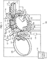
- Fig. 1 is a schematic view illustrating the structural arrangement of the automatic analyzer.
- the automatic analyzer 100 is intended for measuring the reaction solution subjected to chemical reaction within a reaction container 102 so as to perform its component analysis and essentially includes a reaction disk 101; a washing mechanism 103; a spectrophotometer 104; a stirring mechanism 105; a washing tank 106; a first reagent dispensing mechanism 107; a second reagent dispensing mechanism 107a; a washing tank 108; a reagent disk 109; a first sample dispensing mechanism 111; a second sample dispensing mechanism 111a; a washing tank 113; a sample transport mechanism 117; and a controller 118.
- the reaction containers 102 are circumferentially disposed in the reaction disk 101.
- the reaction containers 102 are intended for receiving a mixed solution in which a sample is admixed with a reagent and plurally juxtaposed around the reaction disk 101.
- the sample transport mechanism 117 which transports a sample rack 116 on which sample containers 115 are carried is disposed in the vicinity of the reaction disk 101.
- the first sample dispensing mechanism 111 and the second sample dispensing mechanism 111a which are respectively rotatable and vertically movable are disposed between the reaction disk 101 and the sample transport mechanism 117 and are respectively provided with a sample probe 111b.
- a sample syringe 122 is connected to the sample probes 111b respectively.
- the sample probes 111b move horizontally and arcuately around a rotational axis and vertically moves so as to dispense a sample from the sample containers 115 to the reaction containers 102.
- the reagent disk 109 is a storage which allows e.g. a plurality of reagent bottles 110 in which reagents are received and a plurality of detergent bottles 112 to be circumferentially carried therein.
- the reagent disk 109 is refrigerated.
- the first reagent dispensing mechanism 107 and the second reagent dispensing mechanism 107a which are rotatable and vertically movable are disposed between the reaction disk 101 and the reagent disk 109 and are respectively provided with a reagent probe 120.
- the reagent dispensing mechanism 107 and the reagent dispensing mechanism 107a make the reagent probe 120 move vertically and horizontally.
- a reagent syringe 121 is connected to the reagent probes 120 respectively. Through such reagent syringes 121 via the reagent probes 120, e.g. the reagents, detergents, diluted solutions and pre-treatment reagents aspirated from e.g. the reagent bottles 110, the detergent bottles 112, the diluted solution bottles and the pre-treatment reagent bottles are dispensed to the reaction containers 102.
- the washing mechanism 103 to wash the interior of the reaction containers 102; the spectrophotometer 104 for measuring the absorbance of the light passed through the mixed solution within the reaction containers 102; the stirring mechanism 105 for admixing a sample and a reagent dispensed to the reaction containers 102 and the like are disposed in the circumference of the reaction disk 101.
- the washing tank 108 for the reagent probe 120 is disposed within the moving range of the first reagent dispensing mechanism 107 and the second reagent dispensing mechanism 107a respectively; the washing tank 113 for the sample probe 111b is disposed within the moving range of the first sample dispensing mechanism 111 and the second sample dispensing mechanism 111a respectively; and the washing tank 106 for the stirring mechanism 105 is disposed within the moving range of the stirring mechanism 105.
- the respective mechanisms above are connected to the controller 118, so that their operations are controlled by the controller 118.
- the controller 118 is composed of e.g. a computer and controls the operations of the respective mechanisms above within the automatic analyzer as well as performs the computing operation to calculate the concentrations of the prescribed components of such liquid samples as blood and urine.
- reagent dispensing mechanisms and the sample dispensing mechanisms are the same in structure.
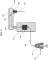
- Fig. 2 the structure of the reagent dispensing mechanism 107 is illustrated with its relevant channel included.
- the arm section 206 of the reagent dispensing mechanism 107 is provided with a probe guide 202 to fix the position of the reagent probe 120 attached to the reagent dispensing mechanism 107.
- a probe guide 202 to fix the position of the reagent probe 120 attached to the reagent dispensing mechanism 107.
- the probe to be exchanged is pulled out of the probe guide 202 and a new probe is inserted into the probe guide 202 with the top cover 205 opened.
- the reagent probe 120 is fixed to the position defined by the probe guide 202.
- the channel of the dispensing mechanism is formed by the reagent probe 120 being interconnected with a tube 201 and a nipple 203.
- the probe corresponds to the portion of the dispensing channel which is exchangeably attached to the tube 201, so that it may not be integrally formed from its tip end with the tube.
- the reagent probe 120 is connected through the tube 201 constituting the dispensing channel to the reagent syringe 121, and a pressure sensor 204 is further provided in the running course of the dispensing channel.
- the dispensing channel is internally filled with the system water (pure water) 301, and the aspiration or discharge of the reagent is carried out with the reagent syringe 121 operated so as to make the system water contained in the dispensing channel discharge or aspirate.
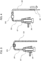
- the dispensing channel including the reagent probe 120 is internally filled with the system water 301 over the connection portion (the position of the nipple 203) between the reagent probe 120 and the tube 201 up to the side of the reagent probe.
- Fig. 4 the condition where the nipple 203 interconnecting the reagent probe 120 and the tube 201 along the dispensing channel is slackened in order to exchange the reagent probe 120 is illustrated in Fig. 4 .
- the connection portion By the connection portion being liberated, it causes the system water 301 contained in the reagent probe 120 to flow under its self-weight, which leads to the liquid dropping from the tip end of the reagent probe 120 or the droplets attaching on the tip end of the probe.
- the droplets attached on the tip end of the probe might cause malfunctions in the mechanism.
- the probe is provided with a liquid surface detection mechanism to automatically detect the liquid surface and automatically control the vertical movement of the dispensing mechanism when dispensing the reagent.
- the liquid surface detection mechanism is configured to detect the liquid surface by detecting a difference in electrostatic capacitance between the probe 120 and the probe guide 202 (defined as a reference potential) which arises when the probe makes into contact with the liquid.
- the present example prevents the system water from dropping from the tip end of the probe and the droplets from attaching on the tip end when exchanging the probe in a simplified manner, thereby, keeping the abovementioned inconveniences from happening.
- Fig. 5 illustrates a flow chart when exchanging the reagent probe 120 according to the present example.
- a maintenance execution button is pushed down to enable the exchange of the reagent probe 120 through a manipulation section of the controller 118 so as to put the automatic analyzer into its maintenance state (at S501).
- the controller 118 makes the reagent dispensing mechanism 107 operate so as to make the reagent probe 120 move to the washing tank 108 for washing the reagent probe 120 (resetting operation at S502).
- the interior and exterior of the reagent probe 120 are washed.
- the probe is internally washed by the system water being discharged from its interior.
- the water by which the exterior of the probe is washed and the system water which is discharged from the interior of the probe are subjected to vacuum suction for removal.
- the plunger disposed in the reagent syringe 121 ends its resetting operation in the state where it has discharged the system water due to washing the interior of the probe.
- the aspiration operation of the reagent syringe 121 is executed after the washing (at S503).
- the controller turns off the energization of the motor of the dispensing mechanism in order to move the dispensing mechanism to a position to facilitate the probe to be exchanged; releases the interlock of the top cover 205; and makes a display on the manipulation section to the effect that the reagent probe 120 is exchangeable (at S504).
- the user opens the top cover 205 and carries out the exchange of the reagent probe 120 (at S505).
- the user closes the top cover 205 and pushes down a reagent probe 120 exchange completion button through the manipulation section (at S506).
- the controller 118 turns on the energization of the motor of the dispensing mechanism and executes the interlocking of the top cover 205.
- the controller makes the reagent dispensing mechanism 107 operate so as to make the reagent probe 120 move to the washing tank 108 for washing the reagent probe 120 (resetting operation at S507). Since the plunger of the syringe performs the aspiration operation when exchanging the probe, it facilitates the discharging operation of the system water during the washing operation to be executed. Thereafter, the controller 118 puts the automatic analyzer into its stand-by state (at S508), thereby, the subsequent operations (such as measurement and maintenance) being executable.
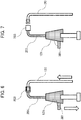
- Performing the aspiration operation of the reagent syringe 121 at the step S503 results in making the reagent probe 120 aspirate the air, so that the system water 301 contained in the reagent probe 120 is replaced with the air as illustrated in Fig. 6 , which invites the state where there is no presence of the system water 301 ahead of the connection portion (nipple 203) (on the side of the reagent probe with respect to the connection portion).
- it dispenses with the liquid dropping from the tip end of the reagent probe 120 and/or the droplets attaching on the tip end even when the nipple 203 is slackened.
- dispensing with the liquid dropping from the tip end of the dispensing probe and/or the droplets attaching on the tip end when exchanging the dispensing probe prevents the mechanisms of the automatic analyzer from causing malfunctions.
- the present invention is not limited to the above embodiment, and may be modified into various manners or developed in various modes.
- the above detailed embodiment is only intended for facilitating the persons skilled in the art to understand the present invention, in which the present invention is not necessary limited to any particular embodiment incorporating the entire features noted herein.
- the case where the reagent probe 120 is exchanged is exemplified, but the same exchanging steps above are also applicable to the sample probe 111b.
Landscapes
- Chemical & Material Sciences (AREA)
- Physics & Mathematics (AREA)
- Health & Medical Sciences (AREA)
- Life Sciences & Earth Sciences (AREA)
- Analytical Chemistry (AREA)
- Biochemistry (AREA)
- General Health & Medical Sciences (AREA)
- General Physics & Mathematics (AREA)
- Immunology (AREA)
- Pathology (AREA)
- Chemical Kinetics & Catalysis (AREA)
- Automatic Analysis And Handling Materials Therefor (AREA)
Abstract
Description
- The present invention relates to an automatic analyzer provided with an exchangeable probe which dispenses a reagent and/or a sample.
- An automatic analyzer, e.g. a biochemical automatic analyzer, performs the component analysis of biosamples such as urine and serum (hereinafter, referred to as a sample). For that purpose, it makes a sample and a reagent dispense in a reaction container for reaction employing a dispensing probe and optically measures the change in hue and turbidity caused in the reaction solution by means of photometers such as a spectrophotometer. Thus, e.g. the smudge and deformation of the probe give large influence on the dispensing precision and the reliability of the automatic analyzer.
- As a result, it is necessary that the probe that cannot be used due to e.g. smudge and malfunction is exchanged (e.g. refer to the disclosure of Patent Literature 1). The probe to dispense a reagent and/or a sample is connected with the channel within the automatic analyzer by a nipple in order to make it exchangeable. Normally, the channel of the automatic analyzer is internally filled with a liquid (system water) which also applies to the interior of the probe. Thus, by removing the nipple with which the probe is connected with the channel for e.g. maintenance, the liquid contained in the probe might drop from the tip end of the probe. According to the conventional automatic analyzers, the countermeasures against such problem are limited to e.g. preparing in advance a receptacle to receive the liquid dropped from the tip end of the probe or arousing cautions to the uses through the manuals.
- [Patent Literature 1]
Japanese Unexamined Patent Application Publication No. 2010-85098 - Since the liquid remains within the probe after washing, the system water might attach on the tip end of the probe in the form of droplets when exchanging the probe so as to cause malfunctions in the mechanism of the automatic analyzer. By dispensing with the liquid dropped from the probe and the droplets attached on the tip end of the probe when exchanging the probe, an automatic analyzer excellent in maintenance and reliability is provided.
- The automatic analyzer according to one embodiment of the present invention includes a probe exchangeably attached to an arm section of a dispensing mechanism; a tube which is connected to the probe and forms a dispensing channel; a syringe which is connected to the tube and discharges or aspirates the system water within the dispensing channel; and a controller, in which the controller makes the syringe aspirate the system water from the dispensing channel such that the system water is removed from the probe before the probe is detached from the arm section.
- By dispensing with the liquid dropping from and the droplets being attached on the tip end of the probe when exchanging the dispensing probe, an automatic analyzer excellent in maintenance and reliability is provided.
- The other technical problems and their solution as well as the novel features of the present invention are elaborated in the detailed description of the invention with reference to the accompanying drawings.
-
-
Fig. 1 is a schematic view illustrating the structural arrangement of the automatic analyzer. -
Fig. 2 is a view illustrating the structural arrangement of the reagent dispensing mechanism. -
Fig. 3 is a view illustrating the state of the dispensing channel before the reagent probe is exchanged according to the prior art. -
Fig. 4 is a view showing that the system water drops from the tip end of the reagent probe and the droplets attach on the tip end. -
Fig. 5 is a flow chart when exchanging the reagent probe. -
Fig. 6 is a view illustrating the state where the reagent probe is exchanged according to the present example. -
Fig. 7 is a view illustrating the state where the reagent probe is exchanged according to the present example. - The preferred embodiment for carrying out the invention is described in detail with reference to the accompanying drawings.
-
Fig. 1 is a schematic view illustrating the structural arrangement of the automatic analyzer. Theautomatic analyzer 100 is intended for measuring the reaction solution subjected to chemical reaction within a reaction container 102 so as to perform its component analysis and essentially includes a reaction disk 101; awashing mechanism 103; aspectrophotometer 104; astirring mechanism 105; awashing tank 106; a firstreagent dispensing mechanism 107; a second reagent dispensing mechanism 107a; awashing tank 108; areagent disk 109; a firstsample dispensing mechanism 111; a secondsample dispensing mechanism 111a; a washing tank 113; a sample transport mechanism 117; and acontroller 118. - The reaction containers 102 are circumferentially disposed in the reaction disk 101. The reaction containers 102 are intended for receiving a mixed solution in which a sample is admixed with a reagent and plurally juxtaposed around the reaction disk 101. The sample transport mechanism 117 which transports a
sample rack 116 on whichsample containers 115 are carried is disposed in the vicinity of the reaction disk 101. - The first
sample dispensing mechanism 111 and the secondsample dispensing mechanism 111a which are respectively rotatable and vertically movable are disposed between the reaction disk 101 and the sample transport mechanism 117 and are respectively provided with asample probe 111b. Asample syringe 122 is connected to thesample probes 111b respectively. Thesample probes 111b move horizontally and arcuately around a rotational axis and vertically moves so as to dispense a sample from thesample containers 115 to the reaction containers 102. - The
reagent disk 109 is a storage which allows e.g. a plurality ofreagent bottles 110 in which reagents are received and a plurality ofdetergent bottles 112 to be circumferentially carried therein. Thereagent disk 109 is refrigerated. - The first
reagent dispensing mechanism 107 and the second reagent dispensing mechanism 107a which are rotatable and vertically movable are disposed between the reaction disk 101 and thereagent disk 109 and are respectively provided with areagent probe 120. Thereagent dispensing mechanism 107 and the reagent dispensing mechanism 107a make thereagent probe 120 move vertically and horizontally. Areagent syringe 121 is connected to thereagent probes 120 respectively. Throughsuch reagent syringes 121 via thereagent probes 120, e.g. the reagents, detergents, diluted solutions and pre-treatment reagents aspirated from e.g. thereagent bottles 110, thedetergent bottles 112, the diluted solution bottles and the pre-treatment reagent bottles are dispensed to the reaction containers 102. - The
washing mechanism 103 to wash the interior of the reaction containers 102; thespectrophotometer 104 for measuring the absorbance of the light passed through the mixed solution within the reaction containers 102; thestirring mechanism 105 for admixing a sample and a reagent dispensed to the reaction containers 102 and the like are disposed in the circumference of the reaction disk 101. - Further, the
washing tank 108 for thereagent probe 120 is disposed within the moving range of the firstreagent dispensing mechanism 107 and the second reagent dispensing mechanism 107a respectively; the washing tank 113 for thesample probe 111b is disposed within the moving range of the firstsample dispensing mechanism 111 and the secondsample dispensing mechanism 111a respectively; and thewashing tank 106 for thestirring mechanism 105 is disposed within the moving range of thestirring mechanism 105. - The respective mechanisms above are connected to the
controller 118, so that their operations are controlled by thecontroller 118. Thecontroller 118 is composed of e.g. a computer and controls the operations of the respective mechanisms above within the automatic analyzer as well as performs the computing operation to calculate the concentrations of the prescribed components of such liquid samples as blood and urine. - Then, the details of the dispensing operations of the dispensing mechanisms are explained with reference to
Fig. 2 . The reagent dispensing mechanisms and the sample dispensing mechanisms are the same in structure. InFig. 2 , the structure of thereagent dispensing mechanism 107 is illustrated with its relevant channel included. - The
arm section 206 of thereagent dispensing mechanism 107 is provided with aprobe guide 202 to fix the position of thereagent probe 120 attached to thereagent dispensing mechanism 107. When exchanging the probe, as the upper face of thearm section 206 is provided with atop cover 205, the probe to be exchanged is pulled out of theprobe guide 202 and a new probe is inserted into theprobe guide 202 with thetop cover 205 opened. Thereagent probe 120 is fixed to the position defined by theprobe guide 202. The channel of the dispensing mechanism is formed by thereagent probe 120 being interconnected with atube 201 and anipple 203. To note, the probe corresponds to the portion of the dispensing channel which is exchangeably attached to thetube 201, so that it may not be integrally formed from its tip end with the tube. Thereagent probe 120 is connected through thetube 201 constituting the dispensing channel to thereagent syringe 121, and apressure sensor 204 is further provided in the running course of the dispensing channel. - During the normal operation, the dispensing channel is internally filled with the system water (pure water) 301, and the aspiration or discharge of the reagent is carried out with the
reagent syringe 121 operated so as to make the system water contained in the dispensing channel discharge or aspirate. Thus, conventionally, when exchanging the reagent probe as well, as illustrated inFig. 3 , the dispensing channel including thereagent probe 120 is internally filled with thesystem water 301 over the connection portion (the position of the nipple 203) between thereagent probe 120 and thetube 201 up to the side of the reagent probe. - In this state, the condition where the
nipple 203 interconnecting thereagent probe 120 and thetube 201 along the dispensing channel is slackened in order to exchange thereagent probe 120 is illustrated inFig. 4 . By the connection portion being liberated, it causes thesystem water 301 contained in thereagent probe 120 to flow under its self-weight, which leads to the liquid dropping from the tip end of thereagent probe 120 or the droplets attaching on the tip end of the probe. Especially, the droplets attached on the tip end of the probe might cause malfunctions in the mechanism. - One of such malfunctions is exemplified herein. Generally speaking, the probe is provided with a liquid surface detection mechanism to automatically detect the liquid surface and automatically control the vertical movement of the dispensing mechanism when dispensing the reagent. The liquid surface detection mechanism is configured to detect the liquid surface by detecting a difference in electrostatic capacitance between the
probe 120 and the probe guide 202 (defined as a reference potential) which arises when the probe makes into contact with the liquid. However, when the probe is pulled out of theprobe guide 202 in the state where the droplets of the system water attach on the tip end of the probe, such droplets attach on the inner side of theprobe guide 202, and inserting a new probe into theprobe guide 202 in this state causes theprobe 120 and theprobe guide 202 to be short-circuited, which invites the malfunction of the liquid surface detection mechanism. - In order to prevent such malfunction, covering the inner side of the
probe guide 202 with an insulator makes it possible to maintain the insulation between theprobe 120 and theprobe guide 202 even when the probe is pulled out of the probe guide in the state where the droplets are attached on the probe. However, since the tolerance between theprobe 120 and theprobe guide 202 is made extremely small in order to prevent theprobe 120 from fluctuating, complicating the structure of theprobe guide 202 leads to increasing the production cost. The present example prevents the system water from dropping from the tip end of the probe and the droplets from attaching on the tip end when exchanging the probe in a simplified manner, thereby, keeping the abovementioned inconveniences from happening. -
Fig. 5 illustrates a flow chart when exchanging thereagent probe 120 according to the present example. To begin with, a maintenance execution button is pushed down to enable the exchange of thereagent probe 120 through a manipulation section of thecontroller 118 so as to put the automatic analyzer into its maintenance state (at S501). Thecontroller 118 makes thereagent dispensing mechanism 107 operate so as to make thereagent probe 120 move to thewashing tank 108 for washing the reagent probe 120 (resetting operation at S502). During the washing operation, the interior and exterior of thereagent probe 120 are washed. The probe is internally washed by the system water being discharged from its interior. The water by which the exterior of the probe is washed and the system water which is discharged from the interior of the probe are subjected to vacuum suction for removal. The plunger disposed in thereagent syringe 121 ends its resetting operation in the state where it has discharged the system water due to washing the interior of the probe. In other words, the aspiration operation of thereagent syringe 121 is executed after the washing (at S503). As with the aspiration operation of thereagent syringe 121 referred to herein, it is necessary that the aspiration volume by which thesystem water 301 left over on the side of thereagent probe 120 with respect to thenipple 203 is replaced with the air be enabled. Then, the controller turns off the energization of the motor of the dispensing mechanism in order to move the dispensing mechanism to a position to facilitate the probe to be exchanged; releases the interlock of thetop cover 205; and makes a display on the manipulation section to the effect that thereagent probe 120 is exchangeable (at S504). After checking such display, the user opens thetop cover 205 and carries out the exchange of the reagent probe 120 (at S505). After finishing exchanging the probe, the user closes thetop cover 205 and pushes down areagent probe 120 exchange completion button through the manipulation section (at S506). Thecontroller 118 turns on the energization of the motor of the dispensing mechanism and executes the interlocking of thetop cover 205. Thereafter, the controller makes thereagent dispensing mechanism 107 operate so as to make thereagent probe 120 move to thewashing tank 108 for washing the reagent probe 120 (resetting operation at S507). Since the plunger of the syringe performs the aspiration operation when exchanging the probe, it facilitates the discharging operation of the system water during the washing operation to be executed. Thereafter, thecontroller 118 puts the automatic analyzer into its stand-by state (at S508), thereby, the subsequent operations (such as measurement and maintenance) being executable. - Performing the aspiration operation of the
reagent syringe 121 at the step S503 results in making thereagent probe 120 aspirate the air, so that thesystem water 301 contained in thereagent probe 120 is replaced with the air as illustrated inFig. 6 , which invites the state where there is no presence of thesystem water 301 ahead of the connection portion (nipple 203) (on the side of the reagent probe with respect to the connection portion). Thus, as illustrated inFig. 7 , it dispenses with the liquid dropping from the tip end of thereagent probe 120 and/or the droplets attaching on the tip end even when thenipple 203 is slackened. - In this way, dispensing with the liquid dropping from the tip end of the dispensing probe and/or the droplets attaching on the tip end when exchanging the dispensing probe prevents the mechanisms of the automatic analyzer from causing malfunctions.
- It should be noted that the present invention is not limited to the above embodiment, and may be modified into various manners or developed in various modes. The above detailed embodiment is only intended for facilitating the persons skilled in the art to understand the present invention, in which the present invention is not necessary limited to any particular embodiment incorporating the entire features noted herein. For instance, the case where the
reagent probe 120 is exchanged is exemplified, but the same exchanging steps above are also applicable to thesample probe 111b. - Further, the case where the syringe is adopted for the actuator to aspirate the water system contained in the probe is exemplified, but an air cylinder or a pump is also adoptable for that purpose.
-
- 100: automatic analyzer
- 101: reaction disk
- 102: reaction container
- 103: washing mechanism
- 104: spectrophotometer
- 105: stirring mechanism
- 106: washing tank (for stirring mechanism)
- 107, 107a: reagent dispensing mechanism
- 108: washing tank (for reagent dispensing mechanism)
- 109: reagent disk
- 110: reagent bottle
- 111, 111a: sample dispensing mechanism
- 111b: sample probe
- 112: detergent bottle
- 113: washing tank (for sample dispensing mechanism)
- 115: sample container
- 116: sample rack
- 117: sample transport mechanism
- 118: controller
- 120: reagent probe
- 121: reagent syringe
- 122: sample syringe
- 201: tube
- 202: probe guide
- 203: nipple
- 204: pressure sensor
- 205: top cover
- 206: arm section
- 301: system water
Claims (7)
- An automatic analyzer comprising:a probe exchangeably attached to an arm section of a dispensing mechanism;a tube which is connected to the probe and forms a dispensing channel;a syringe which is connected to the tube and discharges and/or aspirates system water contained in the dispensing channel; anda controller,wherein the controller makes the syringe aspirate the system water from the dispensing channel such that the system water is removed from the probe before the probe is detached from the arm section.
- The automatic analyzer according to claim 1,
wherein the arm section is provided with a probe guide; and the probe is inserted into the probe guide when the probe is attached to the arm section. - The automatic analyzer according to claim 2 comprising a liquid surface detection mechanism,
wherein the liquid surface detection mechanism detects change in electrostatic capacitance between the probe guide defined as a reference potential and the probe. - The automatic analyzer according to claim 1,
wherein the controller washes the probe before the probe is exchanged and makes the syringe discharge the system water from the probe. - The automatic analyzer according to claim 1,
wherein the controller washes the probe after the probe is exchanged and makes the syringe discharge the system water from the probe. - The automatic analyzer according to claim 1,
wherein the probe aspirates a reagent and/or a sample and discharges the aspirated reagent and/or sample into reaction containers. - The automatic analyzer according to claim 1,
wherein the probe is connected to the tube through a nipple.
Applications Claiming Priority (2)
| Application Number | Priority Date | Filing Date | Title |
|---|---|---|---|
| JP2018178431 | 2018-09-25 | ||
| PCT/JP2019/034915 WO2020066523A1 (en) | 2018-09-25 | 2019-09-05 | Automated analyzer |
Publications (3)
| Publication Number | Publication Date |
|---|---|
| EP3859348A1 true EP3859348A1 (en) | 2021-08-04 |
| EP3859348A4 EP3859348A4 (en) | 2022-06-08 |
| EP3859348B1 EP3859348B1 (en) | 2023-01-11 |
Family
ID=69949939
Family Applications (1)
| Application Number | Title | Priority Date | Filing Date |
|---|---|---|---|
| EP19866062.3A Active EP3859348B1 (en) | 2018-09-25 | 2019-09-05 | Automated analyzer |
Country Status (5)
| Country | Link |
|---|---|
| US (1) | US12638466B2 (en) |
| EP (1) | EP3859348B1 (en) |
| JP (1) | JP7002669B2 (en) |
| CN (1) | CN112740046B (en) |
| WO (1) | WO2020066523A1 (en) |
Family Cites Families (28)
| Publication number | Priority date | Publication date | Assignee | Title |
|---|---|---|---|---|
| JPH0560770A (en) * | 1991-09-04 | 1993-03-12 | Kyowa Medetsukusu Kk | Method and apparatus for sampling specimen in automatic analyzer |
| JP2981070B2 (en) * | 1993-01-18 | 1999-11-22 | 株式会社日立製作所 | Dispensing device capable of detergent cleaning and its cleaning method |
| JPH06241862A (en) * | 1993-02-12 | 1994-09-02 | Olympus Optical Co Ltd | Liquid level detector |
| JPH1010134A (en) * | 1996-06-20 | 1998-01-16 | Hitachi Ltd | Automatic analyzer |
| JP3158084B2 (en) * | 1997-09-25 | 2001-04-23 | アロカ株式会社 | Analytical device with automatic dispensing function |
| US6814936B1 (en) * | 1999-07-01 | 2004-11-09 | Goran Enhorning | Pipette assembly having a small volume disposable tip |
| JP2002333450A (en) * | 2001-05-10 | 2002-11-22 | Matsushita Electric Ind Co Ltd | Dispensing device |
| US7648678B2 (en) * | 2002-12-20 | 2010-01-19 | Dako Denmark A/S | Method and system for pretreatment of tissue slides |
| JP4500081B2 (en) | 2004-03-29 | 2010-07-14 | ベックマン・コールター・インコーポレーテッド | Nozzle cleaning method and nozzle cleaning device |
| CN2762135Y (en) * | 2004-12-13 | 2006-03-01 | 济南金浩峰技术有限公司 | Quantitative, liquid separating and reagent adding device for blood analysing |
| JP4863260B2 (en) * | 2005-11-30 | 2012-01-25 | 東京エレクトロン株式会社 | Liquid level detection apparatus and liquid processing apparatus including the same |
| WO2007071613A1 (en) * | 2005-12-20 | 2007-06-28 | Tecan Trading Ag | Conditioning device for liquid handling system liquids |
| JP2008298493A (en) * | 2007-05-30 | 2008-12-11 | Hitachi High-Technologies Corp | Automatic analyzer |
| US8075854B2 (en) * | 2007-11-08 | 2011-12-13 | The Ohio State University Research Foundation Bioprocessing Innovative Company | Microfluidic chips for rapid multiplex ELISA |
| JP5276340B2 (en) * | 2008-03-17 | 2013-08-28 | ベックマン コールター, インコーポレイテッド | Nozzle cleaning method and nozzle cleaning apparatus |
| JP2010085098A (en) | 2008-09-29 | 2010-04-15 | Olympus Corp | Analyzer and probe preparation method before use |
| JP2012220301A (en) | 2011-04-07 | 2012-11-12 | Medica Tekku Kk | Dispensation apparatus |
| WO2013125536A1 (en) * | 2012-02-22 | 2013-08-29 | 株式会社日立ハイテクノロジーズ | Automatic analysis device |
| JP6241862B2 (en) * | 2013-02-22 | 2017-12-06 | 国立研究開発法人産業技術総合研究所 | Method of configuring highly clean environment system, method of using highly clean environment device, and assembly, startup or maintenance method of device manufacturing apparatus |
| WO2014179584A1 (en) * | 2013-05-01 | 2014-11-06 | Douglas Scientific | Pipette wash |
| CN105917238B (en) * | 2014-01-24 | 2017-09-26 | 株式会社日立高新技术 | Automatic analysis device |
| JP2016015922A (en) * | 2014-07-09 | 2016-02-01 | 株式会社日立ハイテクノロジーズ | Nucleic acid analyzer |
| CN204219385U (en) * | 2014-11-17 | 2015-03-25 | 西安交通大学医学院第一附属医院 | A kind of combination type Kato syringe needle Infusion deploys device |
| EP3081942A1 (en) * | 2015-04-17 | 2016-10-19 | Roche Diagniostics GmbH | Pressure transmission liquid for cellular analyzer, cellular analyzer and method for analyzing a liquid cellular sample |
| DE102015214566A1 (en) * | 2015-07-30 | 2017-02-02 | Hamilton Bonaduz Ag | Pipetting device for pipetting small volumes of liquid |
| JP6610127B2 (en) * | 2015-09-28 | 2019-11-27 | 株式会社島津製作所 | Liquid dispensing apparatus and liquid dispensing method |
| CN106596991A (en) * | 2017-01-17 | 2017-04-26 | 江苏柯伦迪医疗技术有限公司 | Fully automatic biochemical analyzer with gas jetting device and fully automatic biochemical analysis method |
| EP3502656B1 (en) * | 2017-12-22 | 2022-09-21 | Tecan Trading Ag | A pipetting apparatus, a liquid handling system and a method of controlling pipetting |
-
2019
- 2019-09-05 EP EP19866062.3A patent/EP3859348B1/en active Active
- 2019-09-05 US US17/272,675 patent/US12638466B2/en active Active
- 2019-09-05 WO PCT/JP2019/034915 patent/WO2020066523A1/en not_active Ceased
- 2019-09-05 CN CN201980057544.2A patent/CN112740046B/en active Active
- 2019-09-05 JP JP2020548301A patent/JP7002669B2/en active Active
Also Published As
| Publication number | Publication date |
|---|---|
| WO2020066523A1 (en) | 2020-04-02 |
| EP3859348B1 (en) | 2023-01-11 |
| JPWO2020066523A1 (en) | 2021-11-25 |
| CN112740046B (en) | 2024-07-23 |
| US12638466B2 (en) | 2026-05-26 |
| EP3859348A4 (en) | 2022-06-08 |
| CN112740046A (en) | 2021-04-30 |
| JP7002669B2 (en) | 2022-01-20 |
| US20210341506A1 (en) | 2021-11-04 |
Similar Documents
| Publication | Publication Date | Title |
|---|---|---|
| US9513305B2 (en) | Multiple cleaning stations for a dispensing probe | |
| EP2157435B1 (en) | Nozzle cleaning method, nozzle cleaning device, and automatic analyzer | |
| JP6647288B2 (en) | Automatic analyzer and method | |
| EP3767299B1 (en) | Automatic analyzing apparatus, and method for detecting flow path clogging of the automatic analyzing apparatus | |
| US9989549B2 (en) | Automatic analyzer | |
| US20120216610A1 (en) | Automatic analysis apparatus | |
| WO2009154049A1 (en) | Automatic analyzer | |
| CN110869769B (en) | Test kits, test methods, dispensing devices | |
| EP4296685A1 (en) | Automatic analysis device and method for suctioning sample in automatic analysis device | |
| JP2016206112A (en) | Automatic analyzer | |
| CN110568209A (en) | automatic analyzer | |
| JP2014066730A (en) | Automatic analyzing apparatus | |
| EP3859348B1 (en) | Automated analyzer | |
| JP5931540B2 (en) | Automatic analyzer and inspection system | |
| JP6462256B2 (en) | Automatic analyzer | |
| JP5606843B2 (en) | Automatic analyzer | |
| JP6675162B2 (en) | Automatic analyzer | |
| JP3120180U (en) | Automatic analyzer | |
| JP6338898B2 (en) | Automatic analyzer | |
| JP7167037B2 (en) | Abnormal detection method for automatic analyzer and specimen pipetting mechanism | |
| JP7054616B2 (en) | Automatic analyzer | |
| JP7720410B2 (en) | automatic analyzer | |
| WO2019176298A1 (en) | Automatic analysis device | |
| WO2025169633A1 (en) | Automated analyzing device, and waste liquid unit contamination determination method | |
| JP2016090526A (en) | Automatic analyzer |
Legal Events
| Date | Code | Title | Description |
|---|---|---|---|
| STAA | Information on the status of an ep patent application or granted ep patent |
Free format text: STATUS: THE INTERNATIONAL PUBLICATION HAS BEEN MADE |
|
| PUAI | Public reference made under article 153(3) epc to a published international application that has entered the european phase |
Free format text: ORIGINAL CODE: 0009012 |
|
| STAA | Information on the status of an ep patent application or granted ep patent |
Free format text: STATUS: REQUEST FOR EXAMINATION WAS MADE |
|
| 17P | Request for examination filed |
Effective date: 20210302 |
|
| AK | Designated contracting states |
Kind code of ref document: A1 Designated state(s): AL AT BE BG CH CY CZ DE DK EE ES FI FR GB GR HR HU IE IS IT LI LT LU LV MC MK MT NL NO PL PT RO RS SE SI SK SM TR |
|
| DAV | Request for validation of the european patent (deleted) | ||
| DAX | Request for extension of the european patent (deleted) | ||
| A4 | Supplementary search report drawn up and despatched |
Effective date: 20220509 |
|
| RIC1 | Information provided on ipc code assigned before grant |
Ipc: G01N 35/10 20060101AFI20220502BHEP |
|
| GRAP | Despatch of communication of intention to grant a patent |
Free format text: ORIGINAL CODE: EPIDOSNIGR1 |
|
| STAA | Information on the status of an ep patent application or granted ep patent |
Free format text: STATUS: GRANT OF PATENT IS INTENDED |
|
| INTG | Intention to grant announced |
Effective date: 20221103 |
|
| GRAS | Grant fee paid |
Free format text: ORIGINAL CODE: EPIDOSNIGR3 |
|
| GRAA | (expected) grant |
Free format text: ORIGINAL CODE: 0009210 |
|
| STAA | Information on the status of an ep patent application or granted ep patent |
Free format text: STATUS: THE PATENT HAS BEEN GRANTED |
|
| AK | Designated contracting states |
Kind code of ref document: B1 Designated state(s): AL AT BE BG CH CY CZ DE DK EE ES FI FR GB GR HR HU IE IS IT LI LT LU LV MC MK MT NL NO PL PT RO RS SE SI SK SM TR |
|
| REG | Reference to a national code |
Ref country code: GB Ref legal event code: FG4D |
|
| REG | Reference to a national code |
Ref country code: CH Ref legal event code: EP |
|
| REG | Reference to a national code |
Ref country code: DE Ref legal event code: R096 Ref document number: 602019024415 Country of ref document: DE |
|
| REG | Reference to a national code |
Ref country code: IE Ref legal event code: FG4D |
|
| REG | Reference to a national code |
Ref country code: AT Ref legal event code: REF Ref document number: 1543722 Country of ref document: AT Kind code of ref document: T Effective date: 20230215 |
|
| REG | Reference to a national code |
Ref country code: LT Ref legal event code: MG9D |
|
| REG | Reference to a national code |
Ref country code: NL Ref legal event code: MP Effective date: 20230111 |
|
| REG | Reference to a national code |
Ref country code: AT Ref legal event code: MK05 Ref document number: 1543722 Country of ref document: AT Kind code of ref document: T Effective date: 20230111 |
|
| PG25 | Lapsed in a contracting state [announced via postgrant information from national office to epo] |
Ref country code: NL Free format text: LAPSE BECAUSE OF FAILURE TO SUBMIT A TRANSLATION OF THE DESCRIPTION OR TO PAY THE FEE WITHIN THE PRESCRIBED TIME-LIMIT Effective date: 20230111 |
|
| PG25 | Lapsed in a contracting state [announced via postgrant information from national office to epo] |
Ref country code: RS Free format text: LAPSE BECAUSE OF FAILURE TO SUBMIT A TRANSLATION OF THE DESCRIPTION OR TO PAY THE FEE WITHIN THE PRESCRIBED TIME-LIMIT Effective date: 20230111 Ref country code: PT Free format text: LAPSE BECAUSE OF FAILURE TO SUBMIT A TRANSLATION OF THE DESCRIPTION OR TO PAY THE FEE WITHIN THE PRESCRIBED TIME-LIMIT Effective date: 20230511 Ref country code: NO Free format text: LAPSE BECAUSE OF FAILURE TO SUBMIT A TRANSLATION OF THE DESCRIPTION OR TO PAY THE FEE WITHIN THE PRESCRIBED TIME-LIMIT Effective date: 20230411 Ref country code: LV Free format text: LAPSE BECAUSE OF FAILURE TO SUBMIT A TRANSLATION OF THE DESCRIPTION OR TO PAY THE FEE WITHIN THE PRESCRIBED TIME-LIMIT Effective date: 20230111 Ref country code: LT Free format text: LAPSE BECAUSE OF FAILURE TO SUBMIT A TRANSLATION OF THE DESCRIPTION OR TO PAY THE FEE WITHIN THE PRESCRIBED TIME-LIMIT Effective date: 20230111 Ref country code: HR Free format text: LAPSE BECAUSE OF FAILURE TO SUBMIT A TRANSLATION OF THE DESCRIPTION OR TO PAY THE FEE WITHIN THE PRESCRIBED TIME-LIMIT Effective date: 20230111 Ref country code: ES Free format text: LAPSE BECAUSE OF FAILURE TO SUBMIT A TRANSLATION OF THE DESCRIPTION OR TO PAY THE FEE WITHIN THE PRESCRIBED TIME-LIMIT Effective date: 20230111 Ref country code: AT Free format text: LAPSE BECAUSE OF FAILURE TO SUBMIT A TRANSLATION OF THE DESCRIPTION OR TO PAY THE FEE WITHIN THE PRESCRIBED TIME-LIMIT Effective date: 20230111 |
|
| PG25 | Lapsed in a contracting state [announced via postgrant information from national office to epo] |
Ref country code: SE Free format text: LAPSE BECAUSE OF FAILURE TO SUBMIT A TRANSLATION OF THE DESCRIPTION OR TO PAY THE FEE WITHIN THE PRESCRIBED TIME-LIMIT Effective date: 20230111 Ref country code: PL Free format text: LAPSE BECAUSE OF FAILURE TO SUBMIT A TRANSLATION OF THE DESCRIPTION OR TO PAY THE FEE WITHIN THE PRESCRIBED TIME-LIMIT Effective date: 20230111 Ref country code: IS Free format text: LAPSE BECAUSE OF FAILURE TO SUBMIT A TRANSLATION OF THE DESCRIPTION OR TO PAY THE FEE WITHIN THE PRESCRIBED TIME-LIMIT Effective date: 20230511 Ref country code: GR Free format text: LAPSE BECAUSE OF FAILURE TO SUBMIT A TRANSLATION OF THE DESCRIPTION OR TO PAY THE FEE WITHIN THE PRESCRIBED TIME-LIMIT Effective date: 20230412 Ref country code: FI Free format text: LAPSE BECAUSE OF FAILURE TO SUBMIT A TRANSLATION OF THE DESCRIPTION OR TO PAY THE FEE WITHIN THE PRESCRIBED TIME-LIMIT Effective date: 20230111 |
|
| REG | Reference to a national code |
Ref country code: DE Ref legal event code: R097 Ref document number: 602019024415 Country of ref document: DE |
|
| PG25 | Lapsed in a contracting state [announced via postgrant information from national office to epo] |
Ref country code: SM Free format text: LAPSE BECAUSE OF FAILURE TO SUBMIT A TRANSLATION OF THE DESCRIPTION OR TO PAY THE FEE WITHIN THE PRESCRIBED TIME-LIMIT Effective date: 20230111 Ref country code: RO Free format text: LAPSE BECAUSE OF FAILURE TO SUBMIT A TRANSLATION OF THE DESCRIPTION OR TO PAY THE FEE WITHIN THE PRESCRIBED TIME-LIMIT Effective date: 20230111 Ref country code: EE Free format text: LAPSE BECAUSE OF FAILURE TO SUBMIT A TRANSLATION OF THE DESCRIPTION OR TO PAY THE FEE WITHIN THE PRESCRIBED TIME-LIMIT Effective date: 20230111 Ref country code: DK Free format text: LAPSE BECAUSE OF FAILURE TO SUBMIT A TRANSLATION OF THE DESCRIPTION OR TO PAY THE FEE WITHIN THE PRESCRIBED TIME-LIMIT Effective date: 20230111 Ref country code: CZ Free format text: LAPSE BECAUSE OF FAILURE TO SUBMIT A TRANSLATION OF THE DESCRIPTION OR TO PAY THE FEE WITHIN THE PRESCRIBED TIME-LIMIT Effective date: 20230111 |
|
| PLBE | No opposition filed within time limit |
Free format text: ORIGINAL CODE: 0009261 |
|
| STAA | Information on the status of an ep patent application or granted ep patent |
Free format text: STATUS: NO OPPOSITION FILED WITHIN TIME LIMIT |
|
| PG25 | Lapsed in a contracting state [announced via postgrant information from national office to epo] |
Ref country code: SK Free format text: LAPSE BECAUSE OF FAILURE TO SUBMIT A TRANSLATION OF THE DESCRIPTION OR TO PAY THE FEE WITHIN THE PRESCRIBED TIME-LIMIT Effective date: 20230111 |
|
| 26N | No opposition filed |
Effective date: 20231012 |
|
| PG25 | Lapsed in a contracting state [announced via postgrant information from national office to epo] |
Ref country code: SI Free format text: LAPSE BECAUSE OF FAILURE TO SUBMIT A TRANSLATION OF THE DESCRIPTION OR TO PAY THE FEE WITHIN THE PRESCRIBED TIME-LIMIT Effective date: 20230111 |
|
| REG | Reference to a national code |
Ref country code: CH Ref legal event code: PL |
|
| PG25 | Lapsed in a contracting state [announced via postgrant information from national office to epo] |
Ref country code: LU Free format text: LAPSE BECAUSE OF NON-PAYMENT OF DUE FEES Effective date: 20230905 |
|
| REG | Reference to a national code |
Ref country code: BE Ref legal event code: MM Effective date: 20230930 |
|
| GBPC | Gb: european patent ceased through non-payment of renewal fee |
Effective date: 20230905 |
|
| PG25 | Lapsed in a contracting state [announced via postgrant information from national office to epo] |
Ref country code: LU Free format text: LAPSE BECAUSE OF NON-PAYMENT OF DUE FEES Effective date: 20230905 Ref country code: IT Free format text: LAPSE BECAUSE OF FAILURE TO SUBMIT A TRANSLATION OF THE DESCRIPTION OR TO PAY THE FEE WITHIN THE PRESCRIBED TIME-LIMIT Effective date: 20230111 Ref country code: MC Free format text: LAPSE BECAUSE OF FAILURE TO SUBMIT A TRANSLATION OF THE DESCRIPTION OR TO PAY THE FEE WITHIN THE PRESCRIBED TIME-LIMIT Effective date: 20230111 |
|
| REG | Reference to a national code |
Ref country code: IE Ref legal event code: MM4A |
|
| PG25 | Lapsed in a contracting state [announced via postgrant information from national office to epo] |
Ref country code: IE Free format text: LAPSE BECAUSE OF NON-PAYMENT OF DUE FEES Effective date: 20230905 |
|
| PG25 | Lapsed in a contracting state [announced via postgrant information from national office to epo] |
Ref country code: GB Free format text: LAPSE BECAUSE OF NON-PAYMENT OF DUE FEES Effective date: 20230905 |
|
| PG25 | Lapsed in a contracting state [announced via postgrant information from national office to epo] |
Ref country code: CH Free format text: LAPSE BECAUSE OF NON-PAYMENT OF DUE FEES Effective date: 20230930 |
|
| PG25 | Lapsed in a contracting state [announced via postgrant information from national office to epo] |
Ref country code: IE Free format text: LAPSE BECAUSE OF NON-PAYMENT OF DUE FEES Effective date: 20230905 Ref country code: GB Free format text: LAPSE BECAUSE OF NON-PAYMENT OF DUE FEES Effective date: 20230905 Ref country code: CH Free format text: LAPSE BECAUSE OF NON-PAYMENT OF DUE FEES Effective date: 20230930 |
|
| PG25 | Lapsed in a contracting state [announced via postgrant information from national office to epo] |
Ref country code: BE Free format text: LAPSE BECAUSE OF NON-PAYMENT OF DUE FEES Effective date: 20230930 |
|
| PG25 | Lapsed in a contracting state [announced via postgrant information from national office to epo] |
Ref country code: BG Free format text: LAPSE BECAUSE OF FAILURE TO SUBMIT A TRANSLATION OF THE DESCRIPTION OR TO PAY THE FEE WITHIN THE PRESCRIBED TIME-LIMIT Effective date: 20230111 |
|
| PG25 | Lapsed in a contracting state [announced via postgrant information from national office to epo] |
Ref country code: BG Free format text: LAPSE BECAUSE OF FAILURE TO SUBMIT A TRANSLATION OF THE DESCRIPTION OR TO PAY THE FEE WITHIN THE PRESCRIBED TIME-LIMIT Effective date: 20230111 |
|
| PG25 | Lapsed in a contracting state [announced via postgrant information from national office to epo] |
Ref country code: CY Free format text: LAPSE BECAUSE OF FAILURE TO SUBMIT A TRANSLATION OF THE DESCRIPTION OR TO PAY THE FEE WITHIN THE PRESCRIBED TIME-LIMIT; INVALID AB INITIO Effective date: 20190905 |
|
| PG25 | Lapsed in a contracting state [announced via postgrant information from national office to epo] |
Ref country code: HU Free format text: LAPSE BECAUSE OF FAILURE TO SUBMIT A TRANSLATION OF THE DESCRIPTION OR TO PAY THE FEE WITHIN THE PRESCRIBED TIME-LIMIT; INVALID AB INITIO Effective date: 20190905 |
|
| PGFP | Annual fee paid to national office [announced via postgrant information from national office to epo] |
Ref country code: DE Payment date: 20250730 Year of fee payment: 7 |
|
| PGFP | Annual fee paid to national office [announced via postgrant information from national office to epo] |
Ref country code: FR Payment date: 20250808 Year of fee payment: 7 |
|
| PG25 | Lapsed in a contracting state [announced via postgrant information from national office to epo] |
Ref country code: TR Free format text: LAPSE BECAUSE OF FAILURE TO SUBMIT A TRANSLATION OF THE DESCRIPTION OR TO PAY THE FEE WITHIN THE PRESCRIBED TIME-LIMIT Effective date: 20230111 |