EP3859303A1 - Measurement system - Google Patents
Measurement system Download PDFInfo
- Publication number
- EP3859303A1 EP3859303A1 EP19866067.2A EP19866067A EP3859303A1 EP 3859303 A1 EP3859303 A1 EP 3859303A1 EP 19866067 A EP19866067 A EP 19866067A EP 3859303 A1 EP3859303 A1 EP 3859303A1
- Authority
- EP
- European Patent Office
- Prior art keywords
- bubble
- wall
- state
- fluid
- measurement system
- Prior art date
- Legal status (The legal status is an assumption and is not a legal conclusion. Google has not performed a legal analysis and makes no representation as to the accuracy of the status listed.)
- Granted
Links
- UFNYTHZFYPQOIX-UHFFFAOYSA-N NCCC1OCC1 Chemical compound NCCC1OCC1 UFNYTHZFYPQOIX-UHFFFAOYSA-N 0.000 description 1
Images


Classifications
-
- G—PHYSICS
- G01—MEASURING; TESTING
- G01N—INVESTIGATING OR ANALYSING MATERIALS BY DETERMINING THEIR CHEMICAL OR PHYSICAL PROPERTIES
- G01N29/00—Investigating or analysing materials by the use of ultrasonic, sonic or infrasonic waves; Visualisation of the interior of objects by transmitting ultrasonic or sonic waves through the object
- G01N29/02—Analysing fluids
- G01N29/032—Analysing fluids by measuring attenuation of acoustic waves
-
- G—PHYSICS
- G01—MEASURING; TESTING
- G01N—INVESTIGATING OR ANALYSING MATERIALS BY DETERMINING THEIR CHEMICAL OR PHYSICAL PROPERTIES
- G01N13/00—Investigating surface or boundary effects, e.g. wetting power; Investigating diffusion effects; Analysing materials by determining surface, boundary, or diffusion effects
- G01N13/02—Investigating surface tension of liquids
-
- G—PHYSICS
- G01—MEASURING; TESTING
- G01N—INVESTIGATING OR ANALYSING MATERIALS BY DETERMINING THEIR CHEMICAL OR PHYSICAL PROPERTIES
- G01N29/00—Investigating or analysing materials by the use of ultrasonic, sonic or infrasonic waves; Visualisation of the interior of objects by transmitting ultrasonic or sonic waves through the object
- G01N29/04—Analysing solids
- G01N29/06—Visualisation of the interior, e.g. acoustic microscopy
- G01N29/0654—Imaging
-
- G—PHYSICS
- G01—MEASURING; TESTING
- G01N—INVESTIGATING OR ANALYSING MATERIALS BY DETERMINING THEIR CHEMICAL OR PHYSICAL PROPERTIES
- G01N13/00—Investigating surface or boundary effects, e.g. wetting power; Investigating diffusion effects; Analysing materials by determining surface, boundary, or diffusion effects
- G01N13/02—Investigating surface tension of liquids
- G01N2013/0208—Investigating surface tension of liquids by measuring contact angle
-
- G—PHYSICS
- G01—MEASURING; TESTING
- G01N—INVESTIGATING OR ANALYSING MATERIALS BY DETERMINING THEIR CHEMICAL OR PHYSICAL PROPERTIES
- G01N13/00—Investigating surface or boundary effects, e.g. wetting power; Investigating diffusion effects; Analysing materials by determining surface, boundary, or diffusion effects
- G01N13/02—Investigating surface tension of liquids
- G01N2013/0241—Investigating surface tension of liquids bubble, pendant drop, sessile drop methods
-
- G—PHYSICS
- G01—MEASURING; TESTING
- G01N—INVESTIGATING OR ANALYSING MATERIALS BY DETERMINING THEIR CHEMICAL OR PHYSICAL PROPERTIES
- G01N13/00—Investigating surface or boundary effects, e.g. wetting power; Investigating diffusion effects; Analysing materials by determining surface, boundary, or diffusion effects
- G01N13/02—Investigating surface tension of liquids
- G01N2013/0241—Investigating surface tension of liquids bubble, pendant drop, sessile drop methods
- G01N2013/0266—Bubble methods
-
- G—PHYSICS
- G01—MEASURING; TESTING
- G01N—INVESTIGATING OR ANALYSING MATERIALS BY DETERMINING THEIR CHEMICAL OR PHYSICAL PROPERTIES
- G01N2291/00—Indexing codes associated with group G01N29/00
- G01N2291/02—Indexing codes associated with the analysed material
- G01N2291/024—Mixtures
- G01N2291/02433—Gases in liquids, e.g. bubbles, foams
-
- G—PHYSICS
- G01—MEASURING; TESTING
- G01N—INVESTIGATING OR ANALYSING MATERIALS BY DETERMINING THEIR CHEMICAL OR PHYSICAL PROPERTIES
- G01N2291/00—Indexing codes associated with group G01N29/00
- G01N2291/02—Indexing codes associated with the analysed material
- G01N2291/025—Change of phase or condition
- G01N2291/0258—Structural degradation, e.g. fatigue of composites, ageing of oils
Definitions
- the present disclosure relates to a measurement system.
- a measurement system for acquiring the surface state of a solid, including wettability with respect to a liquid, based on the contact angle of a droplet in contact with the solid surface is known.
- PTL patent literature
- the present disclosure aims to provide a measurement system that can acquire the surface state of a solid, including wettability with respect to a liquid, when the solid is submerged in liquid.
- a measurement system includes a detector configured to detect a contact state of a bubble with respect to a wall, the bubble being included in a fluid that is in contact with the wall, and a controller configured to acquire a state of at least one of the wall, the fluid, and the bubble based on the contact state of the bubble with respect to the wall.
- the detector may be configured to output ultrasonic waves towards the bubble and detect the contact state of the bubble based on at least one of ultrasonic waves that pass through the bubble and ultrasonic waves reflected by the bubble. This configuration enables the detector to detect the contact state of the bubble while the detector is located on the outside of the wall, without coming into contact with the fluid. Consequently, the surface state of the solid can be acquired more easily.
- the detector may be configured to generate an ultrasonic image of the bubble and detect the contact state of the bubble based on the ultrasonic image. This configuration enables the contact angle of the bubble to be detected easily based on the shape of the bubble included in the image. Consequently, the surface state of the solid can be acquired more easily.
- the detector may be configured to generate a captured image by imaging a bubble in contact with the wall and detect the contact state of the bubble based on the captured image. This configuration enables the contact angle of the bubble to be detected easily based on the shape of the bubble included in the image. Consequently, the surface state of the solid can be acquired more easily.
- the fluid may be positioned in an area surrounded by the wall, and the detector may be configured to detect the contact state of the bubble on an inside of the area surrounded by the wall. In this way, the contact state of the bubble positioned on the inside of the area surrounded by the wall is detected, enabling easy acquisition of the surface state of the inner wall of a tank retaining the fluid or the inner wall of a tube through which the fluid flows, for example.
- the wall may be at least a portion of an inner wall of a tube through which the fluid flows
- the detector may be configured to detect the contact state of the bubble with respect to the inner wall while the fluid is flowing through the tube. This configuration enables acquisition of the surface state of the inner wall of the tube while the fluid is flowing through the tube.
- the detector may be configured to detect the number of bubbles in contact with the wall at a first time as a first number of bubbles and detect the number of bubbles in contact with the wall at a second time as a second number of bubbles, the second time being a predetermined time after the first time
- the controller may be configured to acquire the state of at least one of the wall, the fluid, and the bubble based on a comparison between the first number of bubbles and the second number of bubbles.
- the controller may be configured to acquire the state of at least one of the wall, the fluid, and the bubble at least two times separated by a predetermined time period and monitor a change in the state. Even if an absolute index, such as the surface free energy, cannot be acquired as the surface state of the wall, this configuration enables the surface state of the wall to be acquired in a relative manner. Consequently, the state of at least one of the wall, the fluid, and the bubble can easily be monitored.
- an absolute index such as the surface free energy
- a measurement system that can acquire the surface state, including wettability with respect to a liquid, when a solid is submerged in liquid is provided.
- a method for acquiring the surface state of a solid, including wettability with respect to a liquid, based on the contact angle of a droplet in contact with the solid surface is known.
- the contact angle of a droplet in contact with the solid surface cannot be measured.
- the surface state of a solid submerged in liquid cannot be acquired based on the contact angle of a droplet.
- the wettability of a liquid with respect to a solid is determined not only by the surface free energy of the solid, but also based on various factors such as the surface roughness of the solid. It is therefore difficult to calculate the surface free energy of a liquid.
- the state of the liquid is not calculated by an absolute standard, the change in state of the liquid needs to be observed based on a relative standard.
- the contact angle of a droplet in contact with a solid surface sometimes cannot be measured accurately when the droplet is small.
- a measurement system 1 includes a controller 10 and a detector 20.
- the detector 20 detects the state of a measurement target 40 that includes a wall 41, a fluid 42, and a bubble 43.
- the wall 41 is a solid.
- the fluid 42 is a liquid.
- the bubble 43 is a gas.
- the bubble 43 in contact with a surface 41a of the solid is defined by a balance in the surface tension acting between each of the solid, the liquid, and the gas.
- the detector 20 detects the contact state of the bubble 43 with respect to the wall 41.
- the contact state of the bubble 43 with respect to the wall 41 may, for example, be represented by the contact angle of the bubble 43 in contact with the wall 41 in the fluid 42, as described below.
- the contact state of the bubble 43 with respect to the wall 41 may be represented by the ease of adhesion of the bubble 43 to the wall 41 in the fluid 42, as described below.
- the contact state of the bubble 43 with respect to the wall 41 is determined based on the state of the wall 41, the state of the fluid 42, and the state of the bubble 43. Accordingly, based on the contact state of the bubble 43 with respect to the wall 41, the controller 10 can acquire the state of at least one of the wall 41, the fluid 42, and the bubble 43. The controller 10 can also acquire a combination of two or more of these states. In other words, the measurement system 1 can acquire the state of at least one of a solid, liquid, and a gas even when the solid remains in contact with the liquid. The measurement system 1 can also acquire a combination of two or more of these states. Consequently, the state of a solid forming the inner wall of a tank that retains a liquid, or the inner wall of a pipe through which liquid flows, for example, can be acquired more easily.
- the measurement target 40 includes the wall 41 that has the surface 41a, the fluid 42 in contact with the surface 41a, and the bubble 43 present in the fluid 42 and in contact with the surface 41a.
- the interface between the solid and the liquid and the interface between the solid and the gas are both flat surfaces along the surface 41a.
- the interface between the liquid and the gas may include a portion of a spherical surface or a portion of a surface that can be approximated to a sphere.
- the cross-section illustrated in FIG. 2 is assumed to be a surface that is orthogonal to the surface 41a of the solid and passes through the center of a spherical surface forming at least a portion of the interface between the liquid and the gas or the center of a surface approximated to at least a portion of the interface between the liquid and the gas.
- the lines representing the surfaces where the solid, the liquid, and the gas are in contact with each other are referred to as triple lines.
- the angle between the line representing the interface between the liquid and the gas and the line representing the surface 41a of the solid in the cross-section is indicated by ⁇ .
- the angle ⁇ is also called the contact angle.
- an interfacial tension acts between each of the solid, the liquid, and the gas.
- a liquid-solid interfacial tension indicated by ⁇ SL acts between the wall 41 and the fluid 42.
- a solid-gas interfacial tension indicated by ys acts between the wall 41 and the bubble 43.
- a liquid-gas interfacial tension indicated by ⁇ L acts between the fluid 42 and the bubble 43. The tensions are balanced with each other along the surface 41a at the intersection of the triple lines. Expression (1) below holds in FIG. 2 .
- ⁇ SL ⁇ L cos ⁇ + ⁇ S
- the solid-gas surface tension is also referred to as the surface free energy of the solid.
- the liquid-gas surface tension is also referred to as the surface free energy of the liquid.
- the magnitude of the contact angle can be determined based on the surface free energy of the solid and the surface free energy of the liquid. A qualitative expression of the tendency in the size of the contact angle is that as the surface free energy of the solid is larger, or as the surface free energy of the liquid is smaller, the contact angle grows larger.
- the state of the wall 41 may be represented by the surface free energy of the solid or by a parameter representing the hydrophilicity or hydrophobicity of the solid.
- the parameter representing the hydrophilicity or hydrophobicity of the solid may, for example, be the contact angle of water with respect to the solid.
- the state of the fluid 42 may be represented by the surface free energy of the liquid.
- the magnitude of the contact angle is determined not only by the surface free energy of the solid, but also based on the surface roughness of the solid.
- the surface state of the solid acquired based on the contact angle includes not only the surface free energy of the solid but also the surface roughness of the solid.
- the controller 10 acquires information from the components of the measurement system 1 and controls the components.
- the controller 10 may include a processor such as a central processing unit (CPU).
- the controller 10 may implement the various functions of the measurement system 1 by executing a predetermined program.
- the controller 10 may include a memory.
- the memory may store various information used for operations of the measurement system 1, programs for implementing the functions of the measurement system 1, and the like.
- the memory may function as a working memory of the controller 10.
- the memory may, for example, be a semiconductor memory.
- the measurement system 1 may include the memory as a separate component from the controller 10.
- the measurement system 1 may further include a user interface (UI) 30.
- the UI 30 may include an input device, such as physical keys or a touch panel, that accepts operation input from a user.
- the UI 30 may include a display device, such as a display or a light emitting element, that displays information reported to the user.
- the UI 30 may include a sound device, such as a speaker, that outputs audio for reporting information to the user.
- the UI 30 is not limited to the above examples and may include various other devices.
- the detector 20 detects the state of the measurement target 40.
- the detector 20 may acquire the state of the measurement target 40 as a side view image from the surface where the wall 41 intersects with the interface between the fluid 42 and the bubble 43.
- the side that the detector 20 detects as a side view of the state of the measurement target 40 is also referred to as the detection side.
- the detection side is assumed to lie in the XZ plane.
- the detector 20 may include an imaging apparatus 21, such as a camera.
- the imaging apparatus 21 may capture an image of the measurement target 40 viewed from the detection side.
- the imaging apparatus 21 may capture an image of the measurement target 40 by detecting various types of electromagnetic waves, such as visible light or infrared light, emitted from the measurement target 40.
- the image of the measurement target 40 captured by the imaging apparatus 21 is also referred to as a captured image.
- the detector 20 may include an ultrasonic transmitter 22 and an ultrasonic receiver 23.
- the ultrasonic transmitter 22 and the ultrasonic receiver 23 are positioned on opposite sides of the measurement target 40. It is assumed that the ultrasonic transmitter 22 is positioned in the negative direction of the y-axis and the ultrasonic receiver 23 in the positive direction of the y-axis from the measurement target 40.
- the detector 20 may acquire the state of the measurement target 40 by transmitting ultrasonic waves 24 from the ultrasonic transmitter 22 to the measurement target 40 and receiving the ultrasonic waves 24 that pass through the measurement target 40 with the ultrasonic receiver 23.
- the ultrasonic waves 24 are absorbed at a predetermined absorption in each of a solid, a liquid, and a gas.
- the absorption of the ultrasonic waves 24 is determined based on the type, state, and the like of the material through which the ultrasonic waves 24 pass.
- the detector 20 can acquire the state of the measurement target 40, which includes the bubble 43 and the fluid 42, based on the difference between the absorption of the ultrasonic waves 24 that pass through the bubble 43 and the absorption of the ultrasonic waves 24 that pass through the fluid 42.
- the detector 20 may move the ultrasonic transmitter 22 and/or the ultrasonic receiver 23 along the detection side. In other words, the detector 20 may move the ultrasonic transmitter 22 and/or the ultrasonic receiver 23 along the x-axis or the z-axis. This enables acquisition of the state of the measurement target 40 as an ultrasonic transmission image of the measurement target 40 from the side.
- the ultrasonic transmission image can include an image representing the shape of the bubble 43 as viewed from the side.
- the detector 20 may further include an ultrasonic transmitter 22 and an ultrasonic receiver 23 positioned on opposite sides of the measurement target 40 along the z-axis.
- the detector 20 may move the ultrasonic transmitter 22 and/or the ultrasonic receiver 23, positioned along the z-axis on opposite sides of the measurement target 40, along the surface 41a of the wall 41. This enables the detector 20 to acquire the distribution of bubbles 43 positioned on the surface 41a in the range of the measurement target 40.
- the ultrasonic transmission image includes a plurality of bubbles 43
- the image representing the shape of the bubble 43 from the side might depict a plurality of bubbles 43 in overlap.
- the detection accuracy of the shape of the bubble 43 would decrease in this case. Even when an image with a plurality of bubbles 43 in overlap is included in the ultrasonic transmission image, the detection accuracy of the shape of the bubble 43 can be increased by the detector 20 acquiring a distribution of the bubbles 43 positioned on the surface 41a.
- the detector 20 may include an ultrasonic wave transceiver configured to transmit and receive ultrasonic waves.
- the detector 20 may acquire the state of the measurement target 40 by transmitting ultrasonic waves towards the measurement target 40 from the ultrasonic wave transceiver and receiving ultrasonic waves reflected by the measurement target 40 with the ultrasonic wave transceiver. By moving the ultrasonic transceiver along the detection side, the detector 20 may acquire the state of the measurement target 40 as an ultrasonic reflection image of the measurement target 40 from the side.
- the ultrasonic transmitter 22 and ultrasonic receiver 23, along with the ultrasonic transceiver, are collectively referred to as an ultrasonic device.
- the ultrasonic transmission image and ultrasonic reflection image are collectively referred to as an ultrasonic image.
- the shape of the portion where the bubble 43 is in contact with the fluid 42 is approximated by an arc 43a, as illustrated in FIG. 2 , in the side view included in the image acquired by the detector 20.
- the shape of the portion where the bubble 43 is in contact with the surface 41a of the wall 41 is approximated by a circle in plan view of the surface 41a (as seen from the positive direction of the z-axis).
- the radius of the circle representing the portion where the bubble 43 is in contact with the surface 41a is defined as b/2.
- the height of the bubble 43 as viewed from the surface 41a is defined as a.
- the shape of the bubble 43 in a side view is represented by a and b.
- the contact angle ( ⁇ ) of the bubble 43 with respect to the surface 41a is calculated by the ⁇ /2 method using a and b as parameters.
- the contact angle ( ⁇ ) of the bubble 43 with respect to the surface 41a can be calculated by various methods other than the ⁇ /2 method, such as the tangent method or curve fitting.
- the contact angle ( ⁇ ) of the bubble 43 with respect to the surface 41a is an element identifying the relationship between ⁇ SL , ys, and ⁇ L , as in Expression (1) above.
- the values of ⁇ SL , ys, and ⁇ L are all unknowns. In other words, when the values of ⁇ SL , ys, and ⁇ L are calculated, further parameters are necessary to calculate three unknowns. For example, by calculating the contact angle ( ⁇ ) for different types of fluids 42, the values of ⁇ SL , ys, and ⁇ L can be calculated.
- W SL is also represented by Expression (4) below based on Expressions (1) and (3).
- W SL ⁇ L 1 ⁇ cos ⁇
- ys is represented as the sum of the following components: the dispersion force component of the solid, represented as ⁇ S d ; the dipole force component of the solid, represented as ⁇ S p ; and the hydrogen bond force component of the solid, represented as ⁇ S h .
- ⁇ L is represented as the sum of the dispersion force component of the liquid, represented as ⁇ L d , the dipole force component of the liquid, represented as ⁇ L p , and the hydrogen bond force component of the liquid, represented as ⁇ L h .
- the adhesive work (W SL ) is represented by Expression (5) below.
- W SL 2 ⁇ S d ⁇ L d + ⁇ S p ⁇ L p + ⁇ S h ⁇ L h
- simultaneous equations with the three unknowns ⁇ S d , ⁇ S p , and ⁇ S h can be set up by acquiring the contact angle of the bubble 43 for three types of liquids for which ⁇ L d , ⁇ L p , and ⁇ L h are known.
- the components included in ys are calculated by solving simultaneous equations with three variables.
- the value of ys, which represents the surface free energy of the solid, is thus calculated by calculating each component included in ys.
- liquids for which the components included in ⁇ L are known include water, n-hexadecane, and methylene iodide.
- the ⁇ L d , ⁇ L p , and ⁇ L h of water can respectively be 29.1 (mN/m), 1.3 (mN/m), and 42.4 (mN/m).
- the ⁇ L d , ⁇ L p , and ⁇ L h of n-hexadecane can respectively be 27.6 (mN/m), 0.0 (mN/m), and 0.0 (mN/m).
- the ⁇ L d , ⁇ L p , and ⁇ L h of methylene iodide can respectively be 46.8 (mN/m), 4.0 (mN/m), and 0.0 (mN/m).
- the measurement system 1 may further include a port in the wall 41 for sampling the fluid 42.
- the measurement system 1 may further include an analysis unit that calculates the ⁇ L d , ⁇ L p , and ⁇ L h of the sampled fluid 42.
- the analysis unit may calculate the ⁇ L d , ⁇ L p , and ⁇ L h of the sampled fluid 42 by various analysis methods, such as X-ray spectroscopy.
- the measurement system 1 may acquire the result from an external apparatus that calculates the ⁇ L d , ⁇ L p , and ⁇ L h of the sampled fluid 42.
- the measurement system 1 may calculate each component of the ys of the wall 41 to calculate the ys.
- the wall 41 may be at least a portion of the inner wall of a tank retaining the fluid 42.
- the wall 41 may be at least a portion of the inner wall of a tube through which the fluid 42 flows.
- the fluid 42 may be positioned in an area surrounded by the wall 41.
- the detector 20 may detect the contact state of the bubble 43 with respect to the wall 41 on the inside of the area surrounded by the wall 41.
- the wall 41 on the inside of the area surrounded by the wall 41 corresponds to the inner wall of the tank or tube.
- the wall 41 is assumed to be at least a portion of the inner wall of a tube through which the fluid 42 flows.
- the measurement system 1 can detect the state of the wall 41 while the fluid 42 remains in contact with the wall 41.
- a droplet 92 is placed in contact with a surface 91a of a solid sample 91 in an atmosphere 93, and the contact angle of the droplet 92 represented by ⁇ ' is measured to acquire the state of the surface 91a of the solid sample 91, as illustrated in FIG. 5 .
- ⁇ SL represents the interfacial tension acting between the solid sample 91 and the droplet 92.
- ys represents the interfacial tension acting between the solid sample 91 and the atmosphere 93, i.e. the surface tension of the solid sample 91.
- ⁇ L represents the interfacial tension acting between the droplet 92 and the atmosphere 93, i.e. the surface tension of the droplet 92.
- the droplet 92 cannot be placed in contact with the surface 91a when the solid sample 91 is immersed in liquid. In other words, to detect the contact angle of the droplet 92 on the surface 91a, the solid sample 91 is prevented from being in contact with a liquid other than the droplet 92.
- the fluid 42 flowing in the tube needs to be temporarily drained for the system according to the comparative example to acquire the state of the surface 41a of the wall 41, which is at least a portion of the inner wall of the tube.
- the fluid 42 need not be drained to detect the state of the wall 41 in the measurement system 1 according to the present embodiment.
- the measurement system 1 according to the present embodiment can therefore detect the state of the wall 41 in-situ.
- the state of the wall 41 includes the surface roughness of the surface 41a of the wall 41 and the surface free energy on the surface 41a.
- the surface roughness of the surface 41a of the wall 41 which is at least a portion of the inner wall of the tube, and the surface free energy on the surface 41a may change due to deterioration of the surface 41a resulting from a chemical reaction on the surface 41a, friction on the surface 41a from the flow of the fluid 42, or the like.
- Chemical reactions on the surface 41a include corrosion, alteration, and the like.
- the measurement system 1 can detect deterioration of the surface 41a of the wall 41 by detecting the state of the wall 41.
- the deterioration of the tube that includes the wall 41 as at least a portion of the inner wall can thereby be monitored while the fluid 42 is still flowing in the tube. Consequently, the inner wall of the tube can easily be monitored.
- the deterioration of the surface 41a can, for example, progress due to peeling of a surface coating applied to the surface 41a, such as a fluororesin coating.
- the imaging apparatus 21 may be inserted inside the tube that includes the wall 41 as at least a portion of the inner wall.
- the imaging apparatus 21 may be positioned in a recess provided on the inner wall of the tube so that the imaging apparatus 21 does not project into the flow path of the fluid 42.
- the imaging apparatus 21 may instead project from the inner wall of the tube into the flow path of the fluid 42.
- the position and orientation of the imaging apparatus 21 may be controlled based on operation input from the user via the UI 30.
- the ultrasonic device may be positioned on the outside of the tube that includes the wall 41 as at least a portion of the inner wall.
- the ultrasonic device may be positioned to enable acquisition of the cross-sectional state of the bubble 43 adhered to the inner wall of the tube.
- the position and orientation of the ultrasonic device may be controlled based on operation input from the user via the UI 30.
- the detector 20 may acquire an image related to the cross-sectional state of the bubble 43 on the detection side or may acquire an image related to the cross-sectional shape of the bubble 43 in a plane inclined at a predetermined angle relative to the detection side.
- the detector 20 may correct the image related to the cross-sectional state of the bubble 43 based on the inclination relative to the detection side.
- the contact state of the bubble 43 with respect to the wall 41 may be represented not only by the contact angle of the bubble 43, but also as the ease of adhesion of the bubble 43 to the wall 41.
- the ease of adhesion of the bubble 43 may be represented by the number of bubbles 43 adhered within a predetermined area of the wall 41.
- the number of bubbles adhered within a predetermined area of the wall 41 is also referred to as the number of adhered bubbles.
- the ease of adhesion of the bubble 43 may be represented by the number of bubbles adhered while the fluid 42 is flowing in the tube at a predetermined flow rate.
- the ease of adhesion of the bubble 43 may be represented based on the number of adhered bubbles when the flow of the fluid 42 in the tube is 0 and the number of adhered bubbles when the flow of the fluid 42 is R.
- the number of adhered bubbles when the flow of the fluid 42 is 0 is designated N 0 .
- the number of adhered bubbles when the flow of the fluid 42 is R is designated N r .
- the value represented by R ⁇ N r /N 0 may be defined in the measurement system 1 as an index representing the ease of adhesion of the bubble 43.
- a function taking R, N r , and N 0 as parameters may be defined in the measurement system 1 as an index representing the ease of adhesion of the bubble 43.
- the ease of adhesion of the bubble 43 may be represented based on the number of adhered bubbles at a first time represented by T 1 and the number of adhered bubbles at a second time represented by T 2 .
- the second time is defined as the time at which a predetermined time has elapsed from the first time.
- the numbers of adhered bubbles at the first time and the second time are referred to as the first number of bubbles and the second number of bubbles.
- the first number of bubbles and the second number of bubbles are represented by N 1 and N 2 . It is assumed that the fluid 42 flows in the tube at a flow rate represented by R from the first time to the second time.
- the value represented by R ⁇ N 2 /N 1 may be defined in the measurement system 1 as an index representing the ease of adhesion of the bubble 43.
- a function taking R, N 1 , and N 2 as parameters may be defined in the measurement system 1 as an index representing the ease of adhesion of the bubble 43.
- the ease of adhesion of the bubble 43 is not limited to the exemplified definitions and may be represented by various other definitions.
- the measurement system 1 may further include a bubble generator 50.
- the bubble generator 50 generates bubbles 43 in the fluid 42 to produce bubbles 43 that adhere to the wall 41.
- the measurement system 1 may use the detector 20 to detect the state of the bubbles 43 generated by the bubble generator 50.
- the bubble generator 50 may be a propeller or the like that stirs an area including the interface between a gas and a liquid.
- the bubble generator 50 may generate the bubbles 43 by mixing a gas into a liquid.
- the bubble generator 50 may be an ultrasonic oscillator that generates ultrasonic waves.
- the bubble generator 50 may turn a gas dissolved in the liquid into the bubbles 43 by directing ultrasonic waves towards the liquid to produce the phenomenon of ultrasonic cavitation.
- the bubble generator 50 may generate the bubbles 43 while the fluid 42 is at rest. This facilitates adhesion of the generated bubbles 43 onto the wall 41. Consequently, the contact angle of the bubble 43 can be measured more easily.
- the bubble generator 50 may generate the bubbles 43 while the fluid 42 is flowing. This facilitates acquisition of the ease of adhesion of the bubble 43.
- the measurement system 1 may further include a flow meter 60.
- the flow meter 60 measures the flow of the fluid 42 flowing through the tube.
- the detector 20 may detect the ease of adhesion of the bubble 43 based on the measurement result of the flow meter 60.
- the bubble generator 50 may control the size of the bubble 43 that adheres to the wall 41. For example, as the bubble 43 is smaller, the bubble 43 can stably continue to be adhered to the wall 41 for a long time. As the bubble 43 is larger, for example, the detector 20 can more easily detect the state of the bubble 43 adhered to the wall 41.
- the detector 20 may detect the contact state of the bubble 43 with respect to the wall 41 at a predetermined timing.
- the controller 10 may acquire the detection result from the detector 20 and store the detection result in the memory.
- the controller 10 may detect a change in the state of the measurement target 40 based on a comparison between the stored detection result and the newly acquired detection result.
- the measurement system 1 may monitor a change in state by acquiring the state of the measurement target 40 at least two times separated by a predetermined time period.
- the predetermined timing may, for example, be once per day or once per month.
- the predetermined timing may be a cyclical timing or may be an irregular timing.
- the predetermined timing may be specified by operation input from the user via the UI 30.
- the measurement system 1 may detect a change in the state of the wall 41 by monitoring the change in state of the measurement target 40. The timing of maintenance of the wall 41 may be determined based on the change in state of the wall 41.
- the measurement system 1 may detect a change in the state of the fluid 42 by monitoring the change in state of the measurement target 40.
- the quality of the fluid 42 may be monitored based on the change in state of the fluid 42.
- the measurement system 1 may detect a change in the state of the bubble 43 by monitoring the change in state of the measurement target 40.
- the quality of gas dissolved in the fluid 42 may be monitored based on the change in state of the bubble 43.
- the quality of the fluid 42 may thereby be monitored.
- the detector 20 may calculate the contact angle of each bubble 43 among a plurality of bubbles 43 included in the measurement target 40.
- the controller 10 may statistically process the contact angles of the bubbles 43, for example by calculating the average, and acquire the state of the measurement target 40 based on the result of the statistical processing.
- the measurement system 1 acquires the state of at least one of the wall 41, the fluid 42, and the bubble 43 by detecting the adhesion state of the bubble 43 to the wall 41.
- the measurement system 1 can also acquire a combination of two or more of these states.
- This configuration can detect the state of the surface 41a of the wall 41 even when the contact angle of a droplet adhered to the wall 41 cannot be detected due to the fluid 42 being in contact with the wall 41. Consequently, a change in the state of the surface 41a of the wall 41 can be monitored while the fluid 42 remains in contact with the wall 41. If the change in the state of the fluid 42 and the bubble 43 is assumed to be negligibly small, the change in the state of the surface 41a of the wall 41 can be monitored to a higher degree of accuracy.
- the change in the state of the surface 41a of the wall 41 can be monitored.
- the measurement system 1 can monitor the quality of the fluid 42 as an industrial product by monitoring the change in the state of the fluid 42.
- the change in the state of the surface 41a of the wall 41 can be monitored.
- the measurement system 1 can monitor the quality of the fluid 42 by monitoring the change in state of the bubble 43.
- the fluid 42 includes a fermented liquid
- the degree of fermentation of the fermented liquid can be monitored.
- the UI 30 may report information to the user such as an image representing the shape of the bubble 43 detected by the detector 20, the calculation result of the contact angle of the bubble 43, the number of adhered bubbles, or the like.
- the UI 30 may report the result of monitoring the measurement target 40 including the change in state of the wall 41, the change in state of the fluid 42, the change in state of the bubble 43, or the like.
Landscapes
- Physics & Mathematics (AREA)
- Health & Medical Sciences (AREA)
- Life Sciences & Earth Sciences (AREA)
- Chemical & Material Sciences (AREA)
- Analytical Chemistry (AREA)
- Biochemistry (AREA)
- General Health & Medical Sciences (AREA)
- General Physics & Mathematics (AREA)
- Immunology (AREA)
- Pathology (AREA)
- Acoustics & Sound (AREA)
- Investigating Or Analyzing Materials By The Use Of Ultrasonic Waves (AREA)
Abstract
Description
- The present application claims priority to
Japanese Patent Application No. 2018-182391 filed September 27, 2018 - The present disclosure relates to a measurement system.
- A measurement system for acquiring the surface state of a solid, including wettability with respect to a liquid, based on the contact angle of a droplet in contact with the solid surface is known. For example, see patent literature (PTL) 1.
- PTL 1:
JP 2017-133924 A - Demand exists for acquiring the surface state of a solid, including wettability with respect to a liquid, when the solid is submerged in liquid.
- The present disclosure aims to provide a measurement system that can acquire the surface state of a solid, including wettability with respect to a liquid, when the solid is submerged in liquid.
- A measurement system according to an embodiment includes a detector configured to detect a contact state of a bubble with respect to a wall, the bubble being included in a fluid that is in contact with the wall, and a controller configured to acquire a state of at least one of the wall, the fluid, and the bubble based on the contact state of the bubble with respect to the wall. This configuration enables acquisition of the state of at least one of a solid, liquid, and a gas even when the solid remains in contact with the liquid. Consequently, the surface state, including wettability with respect to a liquid, of a solid submerged in liquid can be acquired.
- In a measurement system according to an embodiment, the detector may be configured to output ultrasonic waves towards the bubble and detect the contact state of the bubble based on at least one of ultrasonic waves that pass through the bubble and ultrasonic waves reflected by the bubble. This configuration enables the detector to detect the contact state of the bubble while the detector is located on the outside of the wall, without coming into contact with the fluid. Consequently, the surface state of the solid can be acquired more easily.
- In a measurement system according to an embodiment, the detector may be configured to generate an ultrasonic image of the bubble and detect the contact state of the bubble based on the ultrasonic image. This configuration enables the contact angle of the bubble to be detected easily based on the shape of the bubble included in the image. Consequently, the surface state of the solid can be acquired more easily.
- In a measurement system according to an embodiment, the detector may be configured to generate a captured image by imaging a bubble in contact with the wall and detect the contact state of the bubble based on the captured image. This configuration enables the contact angle of the bubble to be detected easily based on the shape of the bubble included in the image. Consequently, the surface state of the solid can be acquired more easily.
- In a measurement system according to an embodiment, the fluid may be positioned in an area surrounded by the wall, and the detector may be configured to detect the contact state of the bubble on an inside of the area surrounded by the wall. In this way, the contact state of the bubble positioned on the inside of the area surrounded by the wall is detected, enabling easy acquisition of the surface state of the inner wall of a tank retaining the fluid or the inner wall of a tube through which the fluid flows, for example.
- In a measurement system according to an embodiment, the wall may be at least a portion of an inner wall of a tube through which the fluid flows, and the detector may be configured to detect the contact state of the bubble with respect to the inner wall while the fluid is flowing through the tube. This configuration enables acquisition of the surface state of the inner wall of the tube while the fluid is flowing through the tube.
- In a measurement system according to an embodiment, the detector may be configured to detect the number of bubbles in contact with the wall at a first time as a first number of bubbles and detect the number of bubbles in contact with the wall at a second time as a second number of bubbles, the second time being a predetermined time after the first time, and the controller may be configured to acquire the state of at least one of the wall, the fluid, and the bubble based on a comparison between the first number of bubbles and the second number of bubbles. This configuration enables the surface state of the wall to be acquired as the ease of adhesion of the bubble. Consequently, the surface state of the wall can be acquired easily even when the contact angle of the bubble is difficult to detect.
- In a measurement system according to an embodiment, the controller may be configured to acquire the state of at least one of the wall, the fluid, and the bubble at least two times separated by a predetermined time period and monitor a change in the state. Even if an absolute index, such as the surface free energy, cannot be acquired as the surface state of the wall, this configuration enables the surface state of the wall to be acquired in a relative manner. Consequently, the state of at least one of the wall, the fluid, and the bubble can easily be monitored.
- According to the present disclosure, a measurement system that can acquire the surface state, including wettability with respect to a liquid, when a solid is submerged in liquid is provided.
- In the accompanying drawings:
-
FIG. 1 is a block diagram illustrating an example configuration of a measurement system according to an embodiment; -
FIG. 2 is a cross-sectional diagram illustrating an example configuration of a measurement target; -
FIG. 3 illustrates an example configuration such that a detector includes an imaging apparatus; -
FIG. 4 illustrates an example configuration such that a detector includes an ultrasonic transmitter and an ultrasonic receiver; -
FIG. 5 is a cross-sectional diagram illustrating an example of measuring the contact angle of a droplet in contact with a solid surface; and -
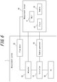
FIG. 6 is a block diagram illustrating an example configuration of a measurement system that further includes a bubble generator. - A method for acquiring the surface state of a solid, including wettability with respect to a liquid, based on the contact angle of a droplet in contact with the solid surface is known.
- When the solid is submerged in a liquid, the contact angle of a droplet in contact with the solid surface cannot be measured. In other words, the surface state of a solid submerged in liquid cannot be acquired based on the contact angle of a droplet. Demand exists for acquiring the surface state of a solid on the inner wall of a tank that retains a liquid, or the inner wall of a pipe through which liquid flows, without draining the liquid.
- The wettability of a liquid with respect to a solid is determined not only by the surface free energy of the solid, but also based on various factors such as the surface roughness of the solid. It is therefore difficult to calculate the surface free energy of a liquid. When the state of the liquid is not calculated by an absolute standard, the change in state of the liquid needs to be observed based on a relative standard.
- The contact angle of a droplet in contact with a solid surface sometimes cannot be measured accurately when the droplet is small. Demand exists for acquiring the state of a solid surface without the need to measure the contact angle.
- A measurement system, according to the present disclosure, that can address these problems is described below.
- As illustrated in
FIG. 1 , a measurement system 1 according to an embodiment of the present disclosure includes acontroller 10 and adetector 20. Thedetector 20 detects the state of ameasurement target 40 that includes awall 41, afluid 42, and abubble 43. Thewall 41 is a solid. Thefluid 42 is a liquid. Thebubble 43 is a gas. Thebubble 43 in contact with asurface 41a of the solid is defined by a balance in the surface tension acting between each of the solid, the liquid, and the gas. Thedetector 20 detects the contact state of thebubble 43 with respect to thewall 41. The contact state of thebubble 43 with respect to thewall 41 may, for example, be represented by the contact angle of thebubble 43 in contact with thewall 41 in thefluid 42, as described below. The contact state of thebubble 43 with respect to thewall 41 may be represented by the ease of adhesion of thebubble 43 to thewall 41 in thefluid 42, as described below. - The contact state of the
bubble 43 with respect to thewall 41 is determined based on the state of thewall 41, the state of the fluid 42, and the state of thebubble 43. Accordingly, based on the contact state of thebubble 43 with respect to thewall 41, thecontroller 10 can acquire the state of at least one of thewall 41, the fluid 42, and thebubble 43. Thecontroller 10 can also acquire a combination of two or more of these states. In other words, the measurement system 1 can acquire the state of at least one of a solid, liquid, and a gas even when the solid remains in contact with the liquid. The measurement system 1 can also acquire a combination of two or more of these states. Consequently, the state of a solid forming the inner wall of a tank that retains a liquid, or the inner wall of a pipe through which liquid flows, for example, can be acquired more easily. - As illustrated in
FIG. 2 , themeasurement target 40 includes thewall 41 that has thesurface 41a, the fluid 42 in contact with thesurface 41a, and thebubble 43 present in the fluid 42 and in contact with thesurface 41a. When thesurface 41a of the solid is flat, the interface between the solid and the liquid and the interface between the solid and the gas are both flat surfaces along thesurface 41a. On the other hand, the interface between the liquid and the gas may include a portion of a spherical surface or a portion of a surface that can be approximated to a sphere. - The cross-section illustrated in
FIG. 2 is assumed to be a surface that is orthogonal to thesurface 41a of the solid and passes through the center of a spherical surface forming at least a portion of the interface between the liquid and the gas or the center of a surface approximated to at least a portion of the interface between the liquid and the gas. In the cross-section, the lines representing the surfaces where the solid, the liquid, and the gas are in contact with each other are referred to as triple lines. The angle between the line representing the interface between the liquid and the gas and the line representing thesurface 41a of the solid in the cross-section is indicated by θ. The angle θ is also called the contact angle. - At the triple lines, an interfacial tension acts between each of the solid, the liquid, and the gas. A liquid-solid interfacial tension indicated by γSL acts between the
wall 41 and the fluid 42. A solid-gas interfacial tension indicated by ys acts between thewall 41 and thebubble 43. A liquid-gas interfacial tension indicated by γL acts between the fluid 42 and thebubble 43. The tensions are balanced with each other along thesurface 41a at the intersection of the triple lines. Expression (1) below holds inFIG. 2 .
- The solid-gas surface tension is also referred to as the surface free energy of the solid. The liquid-gas surface tension is also referred to as the surface free energy of the liquid. The magnitude of the contact angle can be determined based on the surface free energy of the solid and the surface free energy of the liquid. A qualitative expression of the tendency in the size of the contact angle is that as the surface free energy of the solid is larger, or as the surface free energy of the liquid is smaller, the contact angle grows larger. The state of the
wall 41 may be represented by the surface free energy of the solid or by a parameter representing the hydrophilicity or hydrophobicity of the solid. The parameter representing the hydrophilicity or hydrophobicity of the solid may, for example, be the contact angle of water with respect to the solid. The state of the fluid 42 may be represented by the surface free energy of the liquid. When the state of only one of thebubble 43, thewall 41, and the fluid 42 changes and the state of the other two does not change, or changes only to a negligible degree, the contact angle itself corresponds to the target state, enabling management of state changes. - The magnitude of the contact angle is determined not only by the surface free energy of the solid, but also based on the surface roughness of the solid. In other words, the surface state of the solid acquired based on the contact angle includes not only the surface free energy of the solid but also the surface roughness of the solid.
- The
controller 10 acquires information from the components of the measurement system 1 and controls the components. Thecontroller 10 may include a processor such as a central processing unit (CPU). Thecontroller 10 may implement the various functions of the measurement system 1 by executing a predetermined program. - The
controller 10 may include a memory. The memory may store various information used for operations of the measurement system 1, programs for implementing the functions of the measurement system 1, and the like. The memory may function as a working memory of thecontroller 10. The memory may, for example, be a semiconductor memory. The measurement system 1 may include the memory as a separate component from thecontroller 10. - The measurement system 1 may further include a user interface (UI) 30. The
UI 30 may include an input device, such as physical keys or a touch panel, that accepts operation input from a user. TheUI 30 may include a display device, such as a display or a light emitting element, that displays information reported to the user. TheUI 30 may include a sound device, such as a speaker, that outputs audio for reporting information to the user. TheUI 30 is not limited to the above examples and may include various other devices. - The
detector 20 detects the state of themeasurement target 40. Thedetector 20 may acquire the state of themeasurement target 40 as a side view image from the surface where thewall 41 intersects with the interface between the fluid 42 and thebubble 43. The side that thedetector 20 detects as a side view of the state of themeasurement target 40 is also referred to as the detection side. The detection side is assumed to lie in the XZ plane. As illustrated inFIG. 3 , thedetector 20 may include animaging apparatus 21, such as a camera. Theimaging apparatus 21 may capture an image of themeasurement target 40 viewed from the detection side. Theimaging apparatus 21 may capture an image of themeasurement target 40 by detecting various types of electromagnetic waves, such as visible light or infrared light, emitted from themeasurement target 40. The image of themeasurement target 40 captured by theimaging apparatus 21 is also referred to as a captured image. - As illustrated in
FIG. 4 , thedetector 20 may include anultrasonic transmitter 22 and anultrasonic receiver 23. Theultrasonic transmitter 22 and theultrasonic receiver 23 are positioned on opposite sides of themeasurement target 40. It is assumed that theultrasonic transmitter 22 is positioned in the negative direction of the y-axis and theultrasonic receiver 23 in the positive direction of the y-axis from themeasurement target 40. Thedetector 20 may acquire the state of themeasurement target 40 by transmittingultrasonic waves 24 from theultrasonic transmitter 22 to themeasurement target 40 and receiving theultrasonic waves 24 that pass through themeasurement target 40 with theultrasonic receiver 23. - The
ultrasonic waves 24 are absorbed at a predetermined absorption in each of a solid, a liquid, and a gas. The absorption of theultrasonic waves 24 is determined based on the type, state, and the like of the material through which theultrasonic waves 24 pass. Thedetector 20 can acquire the state of themeasurement target 40, which includes thebubble 43 and the fluid 42, based on the difference between the absorption of theultrasonic waves 24 that pass through thebubble 43 and the absorption of theultrasonic waves 24 that pass through the fluid 42. - The
detector 20 may move theultrasonic transmitter 22 and/or theultrasonic receiver 23 along the detection side. In other words, thedetector 20 may move theultrasonic transmitter 22 and/or theultrasonic receiver 23 along the x-axis or the z-axis. This enables acquisition of the state of themeasurement target 40 as an ultrasonic transmission image of themeasurement target 40 from the side. The ultrasonic transmission image can include an image representing the shape of thebubble 43 as viewed from the side. - The
detector 20 may further include anultrasonic transmitter 22 and anultrasonic receiver 23 positioned on opposite sides of themeasurement target 40 along the z-axis. Thedetector 20 may move theultrasonic transmitter 22 and/or theultrasonic receiver 23, positioned along the z-axis on opposite sides of themeasurement target 40, along thesurface 41a of thewall 41. This enables thedetector 20 to acquire the distribution ofbubbles 43 positioned on thesurface 41a in the range of themeasurement target 40. If the ultrasonic transmission image includes a plurality ofbubbles 43, the image representing the shape of thebubble 43 from the side might depict a plurality ofbubbles 43 in overlap. The detection accuracy of the shape of thebubble 43 would decrease in this case. Even when an image with a plurality ofbubbles 43 in overlap is included in the ultrasonic transmission image, the detection accuracy of the shape of thebubble 43 can be increased by thedetector 20 acquiring a distribution of thebubbles 43 positioned on thesurface 41a. - The
detector 20 may include an ultrasonic wave transceiver configured to transmit and receive ultrasonic waves. Thedetector 20 may acquire the state of themeasurement target 40 by transmitting ultrasonic waves towards themeasurement target 40 from the ultrasonic wave transceiver and receiving ultrasonic waves reflected by themeasurement target 40 with the ultrasonic wave transceiver. By moving the ultrasonic transceiver along the detection side, thedetector 20 may acquire the state of themeasurement target 40 as an ultrasonic reflection image of themeasurement target 40 from the side. Theultrasonic transmitter 22 andultrasonic receiver 23, along with the ultrasonic transceiver, are collectively referred to as an ultrasonic device. The ultrasonic transmission image and ultrasonic reflection image are collectively referred to as an ultrasonic image. - The shape of the portion where the
bubble 43 is in contact with the fluid 42 is approximated by anarc 43a, as illustrated inFIG. 2 , in the side view included in the image acquired by thedetector 20. The shape of the portion where thebubble 43 is in contact with thesurface 41a of thewall 41 is approximated by a circle in plan view of thesurface 41a (as seen from the positive direction of the z-axis). The radius of the circle representing the portion where thebubble 43 is in contact with thesurface 41a is defined as b/2. The height of thebubble 43 as viewed from thesurface 41a is defined as a. In other words, the shape of thebubble 43 in a side view is represented by a and b. - The contact angle (θ) of the
bubble 43 with respect to thesurface 41a is calculated by the θ/2 method using a and b as parameters. The contact angle (θ) is represented by Expression (2) below using the θ/2 method.
- The contact angle (θ) of the
bubble 43 with respect to thesurface 41a can be calculated by various methods other than the θ/2 method, such as the tangent method or curve fitting. - The contact angle (θ) of the
bubble 43 with respect to thesurface 41a is an element identifying the relationship between γSL, ys, and γL, as in Expression (1) above. The values of γSL, ys, and γL are all unknowns. In other words, when the values of γSL, ys, and γL are calculated, further parameters are necessary to calculate three unknowns. For example, by calculating the contact angle (θ) for different types offluids 42, the values of γSL, ys, and γL can be calculated. - Here, the work of separating the adhesive bond between the liquid and the solid is represented by γSL, ys, and γL. The work of separating the adhesive bond between the liquid and the solid is referred to as adhesive work and is represented by WSL. WSL is represented by Expression (3) below using the Dupre equation.

- WSL is also represented by Expression (4) below based on Expressions (1) and (3).

- Here, ys is represented as the sum of the following components: the dispersion force component of the solid, represented as γS d; the dipole force component of the solid, represented as γS p; and the hydrogen bond force component of the solid, represented as γS h. Furthermore, γL is represented as the sum of the dispersion force component of the liquid, represented as γL d, the dipole force component of the liquid, represented as γL p, and the hydrogen bond force component of the liquid, represented as γL h. By the extended Fowkes equation, the adhesive work (WSL) is represented by Expression (5) below.

- Expression (6) below holds based on Expressions (4) and (5).

- Based on Expression (6), simultaneous equations with the three unknowns γS d, γS p, and γS h can be set up by acquiring the contact angle of the
bubble 43 for three types of liquids for which γL d, γL p, and γL h are known. In other words, the components included in ys are calculated by solving simultaneous equations with three variables. The value of ys, which represents the surface free energy of the solid, is thus calculated by calculating each component included in ys. - Examples of liquids for which the components included in γL are known include water, n-hexadecane, and methylene iodide. The γL d, γL p, and γL h of water can respectively be 29.1 (mN/m), 1.3 (mN/m), and 42.4 (mN/m). The γL d, γL p, and γL h of n-hexadecane can respectively be 27.6 (mN/m), 0.0 (mN/m), and 0.0 (mN/m). The γL d, γL p, and γL h of methylene iodide can respectively be 46.8 (mN/m), 4.0 (mN/m), and 0.0 (mN/m).
- When the fluid 42 is surrounded by the
wall 41, the measurement system 1 may further include a port in thewall 41 for sampling thefluid 42. The measurement system 1 may further include an analysis unit that calculates the γL d, γL p, and γL h of the sampledfluid 42. The analysis unit may calculate the γL d, γL p, and γL h of the sampledfluid 42 by various analysis methods, such as X-ray spectroscopy. The measurement system 1 may acquire the result from an external apparatus that calculates the γL d, γL p, and γL h of the sampledfluid 42. By acquiring three different types of components as the components of the γL of the fluid 42, the measurement system 1 may calculate each component of the ys of thewall 41 to calculate the ys. - The
wall 41 may be at least a portion of the inner wall of a tank retaining thefluid 42. Thewall 41 may be at least a portion of the inner wall of a tube through which the fluid 42 flows. In other words, the fluid 42 may be positioned in an area surrounded by thewall 41. Thedetector 20 may detect the contact state of thebubble 43 with respect to thewall 41 on the inside of the area surrounded by thewall 41. Thewall 41 on the inside of the area surrounded by thewall 41 corresponds to the inner wall of the tank or tube. - In the present embodiment, the
wall 41 is assumed to be at least a portion of the inner wall of a tube through which the fluid 42 flows. By detecting the state of thewall 41 based on the contact angle of thebubble 43 with respect to thewall 41, the measurement system 1 according to the present embodiment can detect the state of thewall 41 while the fluid 42 remains in contact with thewall 41. - In a system according to a comparative example, a
droplet 92 is placed in contact with asurface 91a of asolid sample 91 in anatmosphere 93, and the contact angle of thedroplet 92 represented by θ' is measured to acquire the state of thesurface 91a of thesolid sample 91, as illustrated inFIG. 5 . InFIG. 5 , γSL represents the interfacial tension acting between thesolid sample 91 and thedroplet 92. Furthermore, ys represents the interfacial tension acting between thesolid sample 91 and theatmosphere 93, i.e. the surface tension of thesolid sample 91. Finally, γL represents the interfacial tension acting between thedroplet 92 and theatmosphere 93, i.e. the surface tension of thedroplet 92. - In the system according to the comparative example, the
droplet 92 cannot be placed in contact with thesurface 91a when thesolid sample 91 is immersed in liquid. In other words, to detect the contact angle of thedroplet 92 on thesurface 91a, thesolid sample 91 is prevented from being in contact with a liquid other than thedroplet 92. The fluid 42 flowing in the tube needs to be temporarily drained for the system according to the comparative example to acquire the state of thesurface 41a of thewall 41, which is at least a portion of the inner wall of the tube. - By contrast, the fluid 42 need not be drained to detect the state of the
wall 41 in the measurement system 1 according to the present embodiment. The measurement system 1 according to the present embodiment can therefore detect the state of thewall 41 in-situ. - The state of the
wall 41 includes the surface roughness of thesurface 41a of thewall 41 and the surface free energy on thesurface 41a. The surface roughness of thesurface 41a of thewall 41, which is at least a portion of the inner wall of the tube, and the surface free energy on thesurface 41a may change due to deterioration of thesurface 41a resulting from a chemical reaction on thesurface 41a, friction on thesurface 41a from the flow of the fluid 42, or the like. Chemical reactions on thesurface 41a include corrosion, alteration, and the like. In other words, the measurement system 1 can detect deterioration of thesurface 41a of thewall 41 by detecting the state of thewall 41. The deterioration of the tube that includes thewall 41 as at least a portion of the inner wall can thereby be monitored while the fluid 42 is still flowing in the tube. Consequently, the inner wall of the tube can easily be monitored. The deterioration of thesurface 41a can, for example, progress due to peeling of a surface coating applied to thesurface 41a, such as a fluororesin coating. - When the
detector 20 includes theimaging apparatus 21, theimaging apparatus 21 may be inserted inside the tube that includes thewall 41 as at least a portion of the inner wall. Theimaging apparatus 21 may be positioned in a recess provided on the inner wall of the tube so that theimaging apparatus 21 does not project into the flow path of the fluid 42. Theimaging apparatus 21 may instead project from the inner wall of the tube into the flow path of the fluid 42. The position and orientation of theimaging apparatus 21 may be controlled based on operation input from the user via theUI 30. - When the
detector 20 includes an ultrasonic device, the ultrasonic device may be positioned on the outside of the tube that includes thewall 41 as at least a portion of the inner wall. The ultrasonic device may be positioned to enable acquisition of the cross-sectional state of thebubble 43 adhered to the inner wall of the tube. The position and orientation of the ultrasonic device may be controlled based on operation input from the user via theUI 30. - The
detector 20 may acquire an image related to the cross-sectional state of thebubble 43 on the detection side or may acquire an image related to the cross-sectional shape of thebubble 43 in a plane inclined at a predetermined angle relative to the detection side. When the cross-section of thebubble 43 is inclined relative to the detection side, thedetector 20 may correct the image related to the cross-sectional state of thebubble 43 based on the inclination relative to the detection side. - The contact state of the
bubble 43 with respect to thewall 41 may be represented not only by the contact angle of thebubble 43, but also as the ease of adhesion of thebubble 43 to thewall 41. The ease of adhesion of thebubble 43 may be represented by the number ofbubbles 43 adhered within a predetermined area of thewall 41. The number of bubbles adhered within a predetermined area of thewall 41 is also referred to as the number of adhered bubbles. When thewall 41 is at least a portion of the inner wall of the tube through which the fluid 42 flows, the ease of adhesion of thebubble 43 may be represented by the number of bubbles adhered while the fluid 42 is flowing in the tube at a predetermined flow rate. - The ease of adhesion of the
bubble 43 may be represented based on the number of adhered bubbles when the flow of the fluid 42 in the tube is 0 and the number of adhered bubbles when the flow of the fluid 42 is R. The number of adhered bubbles when the flow of the fluid 42 is 0 is designated N0. The number of adhered bubbles when the flow of the fluid 42 is R is designated Nr. In this case, the value represented by R × Nr/N0 may be defined in the measurement system 1 as an index representing the ease of adhesion of thebubble 43. A function taking R, Nr, and N0 as parameters may be defined in the measurement system 1 as an index representing the ease of adhesion of thebubble 43. - The ease of adhesion of the
bubble 43 may be represented based on the number of adhered bubbles at a first time represented by T1 and the number of adhered bubbles at a second time represented by T2. The second time is defined as the time at which a predetermined time has elapsed from the first time. The numbers of adhered bubbles at the first time and the second time are referred to as the first number of bubbles and the second number of bubbles. The first number of bubbles and the second number of bubbles are represented by N1 and N2. It is assumed that the fluid 42 flows in the tube at a flow rate represented by R from the first time to the second time. In this case, the value represented by R × N2/N1 may be defined in the measurement system 1 as an index representing the ease of adhesion of thebubble 43. A function taking R, N1, and N2 as parameters may be defined in the measurement system 1 as an index representing the ease of adhesion of thebubble 43. The ease of adhesion of thebubble 43 is not limited to the exemplified definitions and may be represented by various other definitions. - As illustrated in
FIG. 6 , the measurement system 1 according to another embodiment may further include abubble generator 50. At themeasurement target 40, thebubble generator 50 generatesbubbles 43 in the fluid 42 to producebubbles 43 that adhere to thewall 41. The measurement system 1 may use thedetector 20 to detect the state of thebubbles 43 generated by thebubble generator 50. - The
bubble generator 50 may be a propeller or the like that stirs an area including the interface between a gas and a liquid. Thebubble generator 50 may generate thebubbles 43 by mixing a gas into a liquid. Thebubble generator 50 may be an ultrasonic oscillator that generates ultrasonic waves. Thebubble generator 50 may turn a gas dissolved in the liquid into thebubbles 43 by directing ultrasonic waves towards the liquid to produce the phenomenon of ultrasonic cavitation. - The
bubble generator 50 may generate thebubbles 43 while the fluid 42 is at rest. This facilitates adhesion of the generated bubbles 43 onto thewall 41. Consequently, the contact angle of thebubble 43 can be measured more easily. - The
bubble generator 50 may generate thebubbles 43 while the fluid 42 is flowing. This facilitates acquisition of the ease of adhesion of thebubble 43. - The measurement system 1 may further include a
flow meter 60. Theflow meter 60 measures the flow of the fluid 42 flowing through the tube. Thedetector 20 may detect the ease of adhesion of thebubble 43 based on the measurement result of theflow meter 60. - The
bubble generator 50 may control the size of thebubble 43 that adheres to thewall 41. For example, as thebubble 43 is smaller, thebubble 43 can stably continue to be adhered to thewall 41 for a long time. As thebubble 43 is larger, for example, thedetector 20 can more easily detect the state of thebubble 43 adhered to thewall 41. - The
detector 20 may detect the contact state of thebubble 43 with respect to thewall 41 at a predetermined timing. Thecontroller 10 may acquire the detection result from thedetector 20 and store the detection result in the memory. Thecontroller 10 may detect a change in the state of themeasurement target 40 based on a comparison between the stored detection result and the newly acquired detection result. In other words, the measurement system 1 may monitor a change in state by acquiring the state of themeasurement target 40 at least two times separated by a predetermined time period. The predetermined timing may, for example, be once per day or once per month. The predetermined timing may be a cyclical timing or may be an irregular timing. The predetermined timing may be specified by operation input from the user via theUI 30. - The measurement system 1 may detect a change in the state of the
wall 41 by monitoring the change in state of themeasurement target 40. The timing of maintenance of thewall 41 may be determined based on the change in state of thewall 41. The measurement system 1 may detect a change in the state of the fluid 42 by monitoring the change in state of themeasurement target 40. The quality of the fluid 42 may be monitored based on the change in state of the fluid 42. The measurement system 1 may detect a change in the state of thebubble 43 by monitoring the change in state of themeasurement target 40. The quality of gas dissolved in the fluid 42 may be monitored based on the change in state of thebubble 43. The quality of the fluid 42 may thereby be monitored. - The
detector 20 may calculate the contact angle of eachbubble 43 among a plurality ofbubbles 43 included in themeasurement target 40. Thecontroller 10 may statistically process the contact angles of thebubbles 43, for example by calculating the average, and acquire the state of themeasurement target 40 based on the result of the statistical processing. - As described above, the measurement system 1 according to the present embodiment acquires the state of at least one of the
wall 41, the fluid 42, and thebubble 43 by detecting the adhesion state of thebubble 43 to thewall 41. The measurement system 1 can also acquire a combination of two or more of these states. This configuration can detect the state of thesurface 41a of thewall 41 even when the contact angle of a droplet adhered to thewall 41 cannot be detected due to the fluid 42 being in contact with thewall 41. Consequently, a change in the state of thesurface 41a of thewall 41 can be monitored while the fluid 42 remains in contact with thewall 41. If the change in the state of the fluid 42 and thebubble 43 is assumed to be negligibly small, the change in the state of thesurface 41a of thewall 41 can be monitored to a higher degree of accuracy. - If the change in the state of the
surface 41a of thewall 41 is assumed to be negligibly small, the change in the state of the fluid 42 can be monitored. For example, when the fluid 42 is an industrial product such as oil or a beverage, the measurement system 1 can monitor the quality of the fluid 42 as an industrial product by monitoring the change in the state of the fluid 42. - If the change in the state of the
surface 41a of thewall 41 is assumed to be negligibly small, the change in the state of thebubble 43 can be monitored. For example, when a liquid such as a fermented liquid that generates gas is included in the fluid 42, the measurement system 1 can monitor the quality of the fluid 42 by monitoring the change in state of thebubble 43. When the fluid 42 includes a fermented liquid, the degree of fermentation of the fermented liquid can be monitored. - The
UI 30 may report information to the user such as an image representing the shape of thebubble 43 detected by thedetector 20, the calculation result of the contact angle of thebubble 43, the number of adhered bubbles, or the like. TheUI 30 may report the result of monitoring themeasurement target 40 including the change in state of thewall 41, the change in state of the fluid 42, the change in state of thebubble 43, or the like. - Embodiments of the present disclosure have been described with reference to the drawings, but specific configurations are not limited to these embodiments, and a variety of modifications may be made without departing from the spirit and scope thereof.
-
- 1
- Measurement system
- 10
- Controller
- 20
- Detector
- 21
- Imaging apparatus
- 22
- Ultrasonic transmitter
- 23
- Ultrasonic receiver
- 30
- User interface
- 40
- Measurement target
- 41
- Wall
- 41a
- Surface
- 42
- Fluid
- 43
- Bubble
- 43a
- Interface
- 50
- Bubble generator
- 60
- Flow meter
Claims (8)
- A measurement system comprising:a detector configured to detect a contact state of a bubble with respect to a wall, the bubble being included in a fluid that is in contact with the wall; anda controller configured to acquire a state of at least one of the wall, the fluid, and the bubble based on the contact state of the bubble with respect to the wall.
- The measurement system of claim 1, wherein the detector is configured to output ultrasonic waves towards the bubble and detect the contact state of the bubble based on at least one of ultrasonic waves that pass through the bubble and ultrasonic waves reflected by the bubble.
- The measurement system of claim 2, wherein the detector is configured to generate an ultrasonic image of the bubble and detect the contact state of the bubble based on the ultrasonic image.
- The measurement system of claim 1, wherein the detector is configured to generate a captured image by imaging a bubble in contact with the wall and detect the contact state of the bubble based on the captured image.
- The measurement system of any one of claims 1 to 4, wherein
the fluid is positioned in an area surrounded by the wall, and
the detector is configured to detect the contact state of the bubble on an inside of the area surrounded by the wall. - The measurement system of claim 5, wherein
the wall is at least a portion of an inner wall of a tube through which the fluid flows, and
the detector is configured to detect the contact state of the bubble with respect to the inner wall while the fluid is flowing through the tube. - The measurement system of claim 6, wherein
the detector is configured to detect a number of bubbles in contact with the wall at a first time as a first number of bubbles and detect a number of bubbles in contact with the wall at a second time as a second number of bubbles, the second time being a predetermined time after the first time, and
the controller is configured to acquire the state of at least one of the wall, the fluid, and the bubble based on a comparison between the first number of bubbles and the second number of bubbles. - The measurement system of any one of claims 1 to 7, wherein the controller is configured to acquire the state of at least one of the wall, the fluid, and the bubble at least two times separated by a predetermined time period and monitor a change in the state.
Applications Claiming Priority (2)
| Application Number | Priority Date | Filing Date | Title |
|---|---|---|---|
| JP2018182391A JP7172373B2 (en) | 2018-09-27 | 2018-09-27 | measuring system |
| PCT/JP2019/035568 WO2020066600A1 (en) | 2018-09-27 | 2019-09-10 | Measurement system |
Publications (3)
| Publication Number | Publication Date |
|---|---|
| EP3859303A1 true EP3859303A1 (en) | 2021-08-04 |
| EP3859303A4 EP3859303A4 (en) | 2022-06-22 |
| EP3859303B1 EP3859303B1 (en) | 2024-08-28 |
Family
ID=69949670
Family Applications (1)
| Application Number | Title | Priority Date | Filing Date |
|---|---|---|---|
| EP19866067.2A Active EP3859303B1 (en) | 2018-09-27 | 2019-09-10 | Measurement system |
Country Status (5)
| Country | Link |
|---|---|
| US (1) | US20210285860A1 (en) |
| EP (1) | EP3859303B1 (en) |
| JP (1) | JP7172373B2 (en) |
| CN (1) | CN112840198B (en) |
| WO (1) | WO2020066600A1 (en) |
Families Citing this family (1)
| Publication number | Priority date | Publication date | Assignee | Title |
|---|---|---|---|---|
| CN113203662B (en) * | 2021-05-11 | 2022-03-29 | 厦门理工学院 | Contact angle measuring device |
Family Cites Families (16)
| Publication number | Priority date | Publication date | Assignee | Title |
|---|---|---|---|---|
| JPH0850088A (en) * | 1994-08-09 | 1996-02-20 | Toyota Motor Corp | Contact angle measurement method |
| US6711941B2 (en) * | 2000-08-14 | 2004-03-30 | Cambridge Polymer Group, Inc. | Apparatus and methods for measuring extensional rheological properties of a material |
| JP3446751B2 (en) * | 2001-06-15 | 2003-09-16 | トヨタ自動車株式会社 | Contact angle measurement method |
| JP5622266B2 (en) | 2009-08-12 | 2014-11-12 | 国立大学法人名古屋工業大学 | Surface property measuring method and measuring apparatus |
| JP5916509B2 (en) * | 2012-05-15 | 2016-05-11 | 国立大学法人京都大学 | Gas-liquid two-phase flow parameter measuring apparatus and computer program |
| CN102749269B (en) * | 2012-07-05 | 2015-06-24 | 北京永瑞达科贸有限公司 | Determination method and determination apparatus for contact angle and interfacial tension |
| JP6041897B2 (en) | 2012-11-30 | 2016-12-14 | 中国塗料株式会社 | Paint composition used for ship with reduced frictional resistance utilizing gas lubrication function in water, coating film formed from the composition, ship coated with the coating film, method for manufacturing the ship, and reduction of frictional resistance Method for predicting effect, apparatus used for predicting frictional resistance reduction effect, and frictional resistance reducing system used for frictional resistance-reducing ship |
| CN202994615U (en) * | 2012-12-18 | 2013-06-12 | 河北工业大学 | Device for measuring melt surface tension by using maximum bubble method |
| CN103852403B (en) * | 2014-03-13 | 2016-05-11 | 深圳大学 | The measuring method of a kind of cement-based material contact angle and surface energy |
| CN104132870B (en) * | 2014-07-10 | 2017-03-15 | 上海大学 | Surface tension and surface area viscosity determine device |
| EP3210008B1 (en) * | 2014-10-24 | 2024-02-28 | Brighton Technologies LLC | Method and device for detecting substances on surfaces |
| US9652841B2 (en) * | 2015-07-06 | 2017-05-16 | International Business Machines Corporation | System and method for characterizing NANO/MICRO bubbles for particle recovery |
| US11013403B2 (en) * | 2015-09-29 | 2021-05-25 | The Regents Of The University Of California | Methods of diagnosing diseases of mucosal surfaces |
| JP2017133924A (en) | 2016-01-27 | 2017-08-03 | 株式会社豊田中央研究所 | Solid surface free energy calculation system and calculation method |
| JP2018096708A (en) * | 2016-12-08 | 2018-06-21 | キヤノンマシナリー株式会社 | Dispensing nozzle and method for manufacturing dispensing nozzle |
| KR101762703B1 (en) * | 2017-03-03 | 2017-08-04 | 한국지질자원연구원 | Method of measuring the hydrophobicity and hydrophilicity of specimen and apparatus therefor |
-
2018
- 2018-09-27 JP JP2018182391A patent/JP7172373B2/en active Active
-
2019
- 2019-09-10 EP EP19866067.2A patent/EP3859303B1/en active Active
- 2019-09-10 CN CN201980060596.5A patent/CN112840198B/en active Active
- 2019-09-10 WO PCT/JP2019/035568 patent/WO2020066600A1/en not_active Ceased
- 2019-09-10 US US17/275,306 patent/US20210285860A1/en not_active Abandoned
Also Published As
| Publication number | Publication date |
|---|---|
| US20210285860A1 (en) | 2021-09-16 |
| CN112840198A (en) | 2021-05-25 |
| WO2020066600A1 (en) | 2020-04-02 |
| EP3859303B1 (en) | 2024-08-28 |
| EP3859303A4 (en) | 2022-06-22 |
| JP2020051927A (en) | 2020-04-02 |
| JP7172373B2 (en) | 2022-11-16 |
| CN112840198B (en) | 2024-02-20 |
Similar Documents
| Publication | Publication Date | Title |
|---|---|---|
| US9134155B2 (en) | Reynolds number based verification for ultrasonic flow metering systems | |
| US11119049B2 (en) | Particles in liquid detection method and particles in liquid detection system and method to detect particles in the air | |
| JP6104746B2 (en) | Automatic analyzer and analysis method | |
| EP2587250B1 (en) | Automatic analysis device | |
| US10082486B2 (en) | Method for recognizing the presence of liquid in a gas flow | |
| US20180120269A1 (en) | Acoustic gas volume fraction measurement in a multiphase flowing liquid | |
| US20100268486A1 (en) | Ultrasonic multiphase flowmeter, ultrasonic multiphase flow rate measurement program, and multiphase flow rate measurement method using ultrasonic wave | |
| EP2913641A2 (en) | Multiphase flowmeter | |
| EP3859303B1 (en) | Measurement system | |
| US6857323B1 (en) | Two phase flow sensor using tomography techniques | |
| US20210041274A1 (en) | Fluid measurement apparatus, fluid measurement method, and program | |
| JP2002340644A (en) | Ultrasonic flow and flow velocity-measuring instrument and ultrasonic flow and flow velocity-measuring method | |
| JP5458756B2 (en) | Underwater object search support device, underwater object search support method, and program thereof | |
| WO2019047634A1 (en) | Average fluid flow rate measurement system in straight-line distance | |
| US20240393155A1 (en) | Method for determining the proportion of disperse gas phase in liquid | |
| WO2018229914A1 (en) | Ultrasonic measuring device and fluid monitoring system | |
| EP3551969B1 (en) | Method for compensating for venturi effects on pressure sensors in moving water | |
| US10983032B2 (en) | Automatic control of the separation and collection of fluid | |
| JP3552918B2 (en) | Ocean dilution and release equipment for carbon dioxide | |
| EP3312602B1 (en) | Device for measuring the physical parameters of a liquid | |
| CN117147373B (en) | A non-contact liquid concentration detection device and method | |
| EP4679041A1 (en) | Method of and device for determining a flow velocity of a liquid medium | |
| Tanahashi et al. | Application of the ultrasonic technique for monitoring intermittent liquid-gas and liquid-solid flows | |
| CN104142366A (en) | Moisture content online detection method of oil pipelines by acoustic detection technology | |
| JP2006003085A (en) | Vibration diagnostic system |
Legal Events
| Date | Code | Title | Description |
|---|---|---|---|
| STAA | Information on the status of an ep patent application or granted ep patent |
Free format text: STATUS: THE INTERNATIONAL PUBLICATION HAS BEEN MADE |
|
| PUAI | Public reference made under article 153(3) epc to a published international application that has entered the european phase |
Free format text: ORIGINAL CODE: 0009012 |
|
| STAA | Information on the status of an ep patent application or granted ep patent |
Free format text: STATUS: REQUEST FOR EXAMINATION WAS MADE |
|
| 17P | Request for examination filed |
Effective date: 20210317 |
|
| AK | Designated contracting states |
Kind code of ref document: A1 Designated state(s): AL AT BE BG CH CY CZ DE DK EE ES FI FR GB GR HR HU IE IS IT LI LT LU LV MC MK MT NL NO PL PT RO RS SE SI SK SM TR |
|
| DAV | Request for validation of the european patent (deleted) | ||
| DAX | Request for extension of the european patent (deleted) | ||
| RIN1 | Information on inventor provided before grant (corrected) |
Inventor name: TANAKA, HIROAKI Inventor name: OKADA, SYUHEI |
|
| A4 | Supplementary search report drawn up and despatched |
Effective date: 20220525 |
|
| RIC1 | Information provided on ipc code assigned before grant |
Ipc: G01N 29/06 20060101ALI20220519BHEP Ipc: G01N 29/032 20060101ALI20220519BHEP Ipc: G01N 29/02 20060101ALI20220519BHEP Ipc: G01N 13/02 20060101AFI20220519BHEP |
|
| P01 | Opt-out of the competence of the unified patent court (upc) registered |
Effective date: 20230603 |
|
| GRAP | Despatch of communication of intention to grant a patent |
Free format text: ORIGINAL CODE: EPIDOSNIGR1 |
|
| STAA | Information on the status of an ep patent application or granted ep patent |
Free format text: STATUS: GRANT OF PATENT IS INTENDED |
|
| INTG | Intention to grant announced |
Effective date: 20240417 |
|
| GRAS | Grant fee paid |
Free format text: ORIGINAL CODE: EPIDOSNIGR3 |
|
| GRAA | (expected) grant |
Free format text: ORIGINAL CODE: 0009210 |
|
| STAA | Information on the status of an ep patent application or granted ep patent |
Free format text: STATUS: THE PATENT HAS BEEN GRANTED |
|
| AK | Designated contracting states |
Kind code of ref document: B1 Designated state(s): AL AT BE BG CH CY CZ DE DK EE ES FI FR GB GR HR HU IE IS IT LI LT LU LV MC MK MT NL NO PL PT RO RS SE SI SK SM TR |
|
| REG | Reference to a national code |
Ref country code: CH Ref legal event code: EP |
|
| REG | Reference to a national code |
Ref country code: DE Ref legal event code: R096 Ref document number: 602019058042 Country of ref document: DE |
|
| REG | Reference to a national code |
Ref country code: IE Ref legal event code: FG4D |
|
| REG | Reference to a national code |
Ref country code: LT Ref legal event code: MG9D |
|
| PG25 | Lapsed in a contracting state [announced via postgrant information from national office to epo] |
Ref country code: NO Free format text: LAPSE BECAUSE OF FAILURE TO SUBMIT A TRANSLATION OF THE DESCRIPTION OR TO PAY THE FEE WITHIN THE PRESCRIBED TIME-LIMIT Effective date: 20241128 |
|
| REG | Reference to a national code |
Ref country code: AT Ref legal event code: MK05 Ref document number: 1718446 Country of ref document: AT Kind code of ref document: T Effective date: 20240828 |
|
| PG25 | Lapsed in a contracting state [announced via postgrant information from national office to epo] |
Ref country code: NL Free format text: LAPSE BECAUSE OF FAILURE TO SUBMIT A TRANSLATION OF THE DESCRIPTION OR TO PAY THE FEE WITHIN THE PRESCRIBED TIME-LIMIT Effective date: 20240828 Ref country code: GR Free format text: LAPSE BECAUSE OF FAILURE TO SUBMIT A TRANSLATION OF THE DESCRIPTION OR TO PAY THE FEE WITHIN THE PRESCRIBED TIME-LIMIT Effective date: 20241129 Ref country code: PL Free format text: LAPSE BECAUSE OF FAILURE TO SUBMIT A TRANSLATION OF THE DESCRIPTION OR TO PAY THE FEE WITHIN THE PRESCRIBED TIME-LIMIT Effective date: 20240828 Ref country code: PT Free format text: LAPSE BECAUSE OF FAILURE TO SUBMIT A TRANSLATION OF THE DESCRIPTION OR TO PAY THE FEE WITHIN THE PRESCRIBED TIME-LIMIT Effective date: 20241230 Ref country code: FI Free format text: LAPSE BECAUSE OF FAILURE TO SUBMIT A TRANSLATION OF THE DESCRIPTION OR TO PAY THE FEE WITHIN THE PRESCRIBED TIME-LIMIT Effective date: 20240828 |
|
| PG25 | Lapsed in a contracting state [announced via postgrant information from national office to epo] |
Ref country code: BG Free format text: LAPSE BECAUSE OF FAILURE TO SUBMIT A TRANSLATION OF THE DESCRIPTION OR TO PAY THE FEE WITHIN THE PRESCRIBED TIME-LIMIT Effective date: 20240828 |
|
| PG25 | Lapsed in a contracting state [announced via postgrant information from national office to epo] |
Ref country code: LV Free format text: LAPSE BECAUSE OF FAILURE TO SUBMIT A TRANSLATION OF THE DESCRIPTION OR TO PAY THE FEE WITHIN THE PRESCRIBED TIME-LIMIT Effective date: 20240828 |
|
| REG | Reference to a national code |
Ref country code: NL Ref legal event code: MP Effective date: 20240828 |
|
| PG25 | Lapsed in a contracting state [announced via postgrant information from national office to epo] |
Ref country code: AT Free format text: LAPSE BECAUSE OF FAILURE TO SUBMIT A TRANSLATION OF THE DESCRIPTION OR TO PAY THE FEE WITHIN THE PRESCRIBED TIME-LIMIT Effective date: 20240828 Ref country code: IS Free format text: LAPSE BECAUSE OF FAILURE TO SUBMIT A TRANSLATION OF THE DESCRIPTION OR TO PAY THE FEE WITHIN THE PRESCRIBED TIME-LIMIT Effective date: 20241228 |
|
| PG25 | Lapsed in a contracting state [announced via postgrant information from national office to epo] |
Ref country code: HR Free format text: LAPSE BECAUSE OF FAILURE TO SUBMIT A TRANSLATION OF THE DESCRIPTION OR TO PAY THE FEE WITHIN THE PRESCRIBED TIME-LIMIT Effective date: 20240828 |
|
| PG25 | Lapsed in a contracting state [announced via postgrant information from national office to epo] |
Ref country code: RS Free format text: LAPSE BECAUSE OF FAILURE TO SUBMIT A TRANSLATION OF THE DESCRIPTION OR TO PAY THE FEE WITHIN THE PRESCRIBED TIME-LIMIT Effective date: 20241128 Ref country code: ES Free format text: LAPSE BECAUSE OF FAILURE TO SUBMIT A TRANSLATION OF THE DESCRIPTION OR TO PAY THE FEE WITHIN THE PRESCRIBED TIME-LIMIT Effective date: 20240828 |
|
| PG25 | Lapsed in a contracting state [announced via postgrant information from national office to epo] |
Ref country code: RS Free format text: LAPSE BECAUSE OF FAILURE TO SUBMIT A TRANSLATION OF THE DESCRIPTION OR TO PAY THE FEE WITHIN THE PRESCRIBED TIME-LIMIT Effective date: 20241128 Ref country code: PT Free format text: LAPSE BECAUSE OF FAILURE TO SUBMIT A TRANSLATION OF THE DESCRIPTION OR TO PAY THE FEE WITHIN THE PRESCRIBED TIME-LIMIT Effective date: 20241230 Ref country code: PL Free format text: LAPSE BECAUSE OF FAILURE TO SUBMIT A TRANSLATION OF THE DESCRIPTION OR TO PAY THE FEE WITHIN THE PRESCRIBED TIME-LIMIT Effective date: 20240828 Ref country code: NO Free format text: LAPSE BECAUSE OF FAILURE TO SUBMIT A TRANSLATION OF THE DESCRIPTION OR TO PAY THE FEE WITHIN THE PRESCRIBED TIME-LIMIT Effective date: 20241128 Ref country code: NL Free format text: LAPSE BECAUSE OF FAILURE TO SUBMIT A TRANSLATION OF THE DESCRIPTION OR TO PAY THE FEE WITHIN THE PRESCRIBED TIME-LIMIT Effective date: 20240828 Ref country code: LV Free format text: LAPSE BECAUSE OF FAILURE TO SUBMIT A TRANSLATION OF THE DESCRIPTION OR TO PAY THE FEE WITHIN THE PRESCRIBED TIME-LIMIT Effective date: 20240828 Ref country code: IS Free format text: LAPSE BECAUSE OF FAILURE TO SUBMIT A TRANSLATION OF THE DESCRIPTION OR TO PAY THE FEE WITHIN THE PRESCRIBED TIME-LIMIT Effective date: 20241228 Ref country code: HR Free format text: LAPSE BECAUSE OF FAILURE TO SUBMIT A TRANSLATION OF THE DESCRIPTION OR TO PAY THE FEE WITHIN THE PRESCRIBED TIME-LIMIT Effective date: 20240828 Ref country code: GR Free format text: LAPSE BECAUSE OF FAILURE TO SUBMIT A TRANSLATION OF THE DESCRIPTION OR TO PAY THE FEE WITHIN THE PRESCRIBED TIME-LIMIT Effective date: 20241129 Ref country code: FI Free format text: LAPSE BECAUSE OF FAILURE TO SUBMIT A TRANSLATION OF THE DESCRIPTION OR TO PAY THE FEE WITHIN THE PRESCRIBED TIME-LIMIT Effective date: 20240828 Ref country code: ES Free format text: LAPSE BECAUSE OF FAILURE TO SUBMIT A TRANSLATION OF THE DESCRIPTION OR TO PAY THE FEE WITHIN THE PRESCRIBED TIME-LIMIT Effective date: 20240828 Ref country code: BG Free format text: LAPSE BECAUSE OF FAILURE TO SUBMIT A TRANSLATION OF THE DESCRIPTION OR TO PAY THE FEE WITHIN THE PRESCRIBED TIME-LIMIT Effective date: 20240828 Ref country code: AT Free format text: LAPSE BECAUSE OF FAILURE TO SUBMIT A TRANSLATION OF THE DESCRIPTION OR TO PAY THE FEE WITHIN THE PRESCRIBED TIME-LIMIT Effective date: 20240828 |
|
| PG25 | Lapsed in a contracting state [announced via postgrant information from national office to epo] |
Ref country code: RO Free format text: LAPSE BECAUSE OF FAILURE TO SUBMIT A TRANSLATION OF THE DESCRIPTION OR TO PAY THE FEE WITHIN THE PRESCRIBED TIME-LIMIT Effective date: 20240828 Ref country code: DK Free format text: LAPSE BECAUSE OF FAILURE TO SUBMIT A TRANSLATION OF THE DESCRIPTION OR TO PAY THE FEE WITHIN THE PRESCRIBED TIME-LIMIT Effective date: 20240828 Ref country code: SM Free format text: LAPSE BECAUSE OF FAILURE TO SUBMIT A TRANSLATION OF THE DESCRIPTION OR TO PAY THE FEE WITHIN THE PRESCRIBED TIME-LIMIT Effective date: 20240828 |
|
| PG25 | Lapsed in a contracting state [announced via postgrant information from national office to epo] |
Ref country code: EE Free format text: LAPSE BECAUSE OF FAILURE TO SUBMIT A TRANSLATION OF THE DESCRIPTION OR TO PAY THE FEE WITHIN THE PRESCRIBED TIME-LIMIT Effective date: 20240828 |
|
| PG25 | Lapsed in a contracting state [announced via postgrant information from national office to epo] |
Ref country code: CZ Free format text: LAPSE BECAUSE OF FAILURE TO SUBMIT A TRANSLATION OF THE DESCRIPTION OR TO PAY THE FEE WITHIN THE PRESCRIBED TIME-LIMIT Effective date: 20240828 |
|
| PG25 | Lapsed in a contracting state [announced via postgrant information from national office to epo] |
Ref country code: IT Free format text: LAPSE BECAUSE OF FAILURE TO SUBMIT A TRANSLATION OF THE DESCRIPTION OR TO PAY THE FEE WITHIN THE PRESCRIBED TIME-LIMIT Effective date: 20240828 Ref country code: SK Free format text: LAPSE BECAUSE OF FAILURE TO SUBMIT A TRANSLATION OF THE DESCRIPTION OR TO PAY THE FEE WITHIN THE PRESCRIBED TIME-LIMIT Effective date: 20240828 |
|
| REG | Reference to a national code |
Ref country code: CH Ref legal event code: PL |
|
| PG25 | Lapsed in a contracting state [announced via postgrant information from national office to epo] |
Ref country code: LU Free format text: LAPSE BECAUSE OF NON-PAYMENT OF DUE FEES Effective date: 20240910 |
|
| REG | Reference to a national code |
Ref country code: DE Ref legal event code: R097 Ref document number: 602019058042 Country of ref document: DE |
|
| PLBE | No opposition filed within time limit |
Free format text: ORIGINAL CODE: 0009261 |
|
| STAA | Information on the status of an ep patent application or granted ep patent |
Free format text: STATUS: NO OPPOSITION FILED WITHIN TIME LIMIT |
|
| PG25 | Lapsed in a contracting state [announced via postgrant information from national office to epo] |
Ref country code: MC Free format text: LAPSE BECAUSE OF FAILURE TO SUBMIT A TRANSLATION OF THE DESCRIPTION OR TO PAY THE FEE WITHIN THE PRESCRIBED TIME-LIMIT Effective date: 20240828 |
|
| REG | Reference to a national code |
Ref country code: BE Ref legal event code: MM Effective date: 20240930 |
|
| PG25 | Lapsed in a contracting state [announced via postgrant information from national office to epo] |
Ref country code: BE Free format text: LAPSE BECAUSE OF NON-PAYMENT OF DUE FEES Effective date: 20240930 |
|
| PG25 | Lapsed in a contracting state [announced via postgrant information from national office to epo] |
Ref country code: CH Free format text: LAPSE BECAUSE OF NON-PAYMENT OF DUE FEES Effective date: 20240930 |
|
| PG25 | Lapsed in a contracting state [announced via postgrant information from national office to epo] |
Ref country code: IE Free format text: LAPSE BECAUSE OF NON-PAYMENT OF DUE FEES Effective date: 20240910 |
|
| 26N | No opposition filed |
Effective date: 20250530 |
|
| PG25 | Lapsed in a contracting state [announced via postgrant information from national office to epo] |
Ref country code: SE Free format text: LAPSE BECAUSE OF FAILURE TO SUBMIT A TRANSLATION OF THE DESCRIPTION OR TO PAY THE FEE WITHIN THE PRESCRIBED TIME-LIMIT Effective date: 20240828 |
|
| PGFP | Annual fee paid to national office [announced via postgrant information from national office to epo] |
Ref country code: DE Payment date: 20250820 Year of fee payment: 7 |
|
| PGFP | Annual fee paid to national office [announced via postgrant information from national office to epo] |
Ref country code: GB Payment date: 20250822 Year of fee payment: 7 |
|
| PGFP | Annual fee paid to national office [announced via postgrant information from national office to epo] |
Ref country code: FR Payment date: 20250821 Year of fee payment: 7 |
|
| PG25 | Lapsed in a contracting state [announced via postgrant information from national office to epo] |
Ref country code: CY Free format text: LAPSE BECAUSE OF FAILURE TO SUBMIT A TRANSLATION OF THE DESCRIPTION OR TO PAY THE FEE WITHIN THE PRESCRIBED TIME-LIMIT; INVALID AB INITIO Effective date: 20190910 |
|
| PG25 | Lapsed in a contracting state [announced via postgrant information from national office to epo] |
Ref country code: HU Free format text: LAPSE BECAUSE OF FAILURE TO SUBMIT A TRANSLATION OF THE DESCRIPTION OR TO PAY THE FEE WITHIN THE PRESCRIBED TIME-LIMIT; INVALID AB INITIO Effective date: 20190910 |