EP3859293A1 - Magnet temperature estimating device for motor, hybrid vehicle provided with the same, and method of estimating magnet temperature - Google Patents
Magnet temperature estimating device for motor, hybrid vehicle provided with the same, and method of estimating magnet temperature Download PDFInfo
- Publication number
- EP3859293A1 EP3859293A1 EP20215975.2A EP20215975A EP3859293A1 EP 3859293 A1 EP3859293 A1 EP 3859293A1 EP 20215975 A EP20215975 A EP 20215975A EP 3859293 A1 EP3859293 A1 EP 3859293A1
- Authority
- EP
- European Patent Office
- Prior art keywords
- magnet
- temperature
- motor
- induced voltage
- rotor
- Prior art date
- Legal status (The legal status is an assumption and is not a legal conclusion. Google has not performed a legal analysis and makes no representation as to the accuracy of the status listed.)
- Granted
Links
- 238000000034 method Methods 0.000 title claims description 35
- 238000001228 spectrum Methods 0.000 claims abstract description 37
- 238000001514 detection method Methods 0.000 claims abstract description 27
- 230000004044 response Effects 0.000 claims abstract description 4
- 230000002159 abnormal effect Effects 0.000 claims description 9
- 230000004907 flux Effects 0.000 description 81
- 230000001105 regulatory effect Effects 0.000 description 53
- 230000008859 change Effects 0.000 description 26
- 230000002123 temporal effect Effects 0.000 description 22
- 230000001276 controlling effect Effects 0.000 description 17
- 230000005540 biological transmission Effects 0.000 description 12
- 238000012545 processing Methods 0.000 description 9
- 238000005070 sampling Methods 0.000 description 8
- 238000004364 calculation method Methods 0.000 description 7
- 230000008569 process Effects 0.000 description 7
- 230000006870 function Effects 0.000 description 6
- 230000004308 accommodation Effects 0.000 description 5
- 238000007796 conventional method Methods 0.000 description 4
- 238000001816 cooling Methods 0.000 description 4
- 230000004888 barrier function Effects 0.000 description 3
- 238000010586 diagram Methods 0.000 description 3
- 230000000694 effects Effects 0.000 description 3
- 239000000446 fuel Substances 0.000 description 3
- 230000007246 mechanism Effects 0.000 description 3
- 230000005856 abnormality Effects 0.000 description 2
- 230000001133 acceleration Effects 0.000 description 2
- 238000006243 chemical reaction Methods 0.000 description 2
- 238000001914 filtration Methods 0.000 description 2
- 230000006698 induction Effects 0.000 description 2
- 238000010030 laminating Methods 0.000 description 2
- 239000002184 metal Substances 0.000 description 2
- 229910052751 metal Inorganic materials 0.000 description 2
- 238000012544 monitoring process Methods 0.000 description 2
- 230000007935 neutral effect Effects 0.000 description 2
- 230000008929 regeneration Effects 0.000 description 2
- 238000011069 regeneration method Methods 0.000 description 2
- 238000004804 winding Methods 0.000 description 2
- 206010014357 Electric shock Diseases 0.000 description 1
- 239000004606 Fillers/Extenders Substances 0.000 description 1
- 229910000828 alnico Inorganic materials 0.000 description 1
- 238000004458 analytical method Methods 0.000 description 1
- 238000002485 combustion reaction Methods 0.000 description 1
- 230000006835 compression Effects 0.000 description 1
- 238000007906 compression Methods 0.000 description 1
- 239000002826 coolant Substances 0.000 description 1
- 230000007423 decrease Effects 0.000 description 1
- 238000013461 design Methods 0.000 description 1
- 238000005516 engineering process Methods 0.000 description 1
- 239000000284 extract Substances 0.000 description 1
- 239000000463 material Substances 0.000 description 1
- 229910001172 neodymium magnet Inorganic materials 0.000 description 1
- 238000010248 power generation Methods 0.000 description 1
- 230000002441 reversible effect Effects 0.000 description 1
- 229910000938 samarium–cobalt magnet Inorganic materials 0.000 description 1
- 230000001360 synchronised effect Effects 0.000 description 1
- 229910000859 α-Fe Inorganic materials 0.000 description 1
Images


Classifications
-
- G—PHYSICS
- G01—MEASURING; TESTING
- G01K—MEASURING TEMPERATURE; MEASURING QUANTITY OF HEAT; THERMALLY-SENSITIVE ELEMENTS NOT OTHERWISE PROVIDED FOR
- G01K7/00—Measuring temperature based on the use of electric or magnetic elements directly sensitive to heat ; Power supply therefor, e.g. using thermoelectric elements
- G01K7/36—Measuring temperature based on the use of electric or magnetic elements directly sensitive to heat ; Power supply therefor, e.g. using thermoelectric elements using magnetic elements, e.g. magnets, coils
-
- B—PERFORMING OPERATIONS; TRANSPORTING
- B60—VEHICLES IN GENERAL
- B60K—ARRANGEMENT OR MOUNTING OF PROPULSION UNITS OR OF TRANSMISSIONS IN VEHICLES; ARRANGEMENT OR MOUNTING OF PLURAL DIVERSE PRIME-MOVERS IN VEHICLES; AUXILIARY DRIVES FOR VEHICLES; INSTRUMENTATION OR DASHBOARDS FOR VEHICLES; ARRANGEMENTS IN CONNECTION WITH COOLING, AIR INTAKE, GAS EXHAUST OR FUEL SUPPLY OF PROPULSION UNITS IN VEHICLES
- B60K6/00—Arrangement or mounting of plural diverse prime-movers for mutual or common propulsion, e.g. hybrid propulsion systems comprising electric motors and internal combustion engines ; Control systems therefor, i.e. systems controlling two or more prime movers, or controlling one of these prime movers and any of the transmission, drive or drive units Informative references: mechanical gearings with secondary electric drive F16H3/72; arrangements for handling mechanical energy structurally associated with the dynamo-electric machine H02K7/00; machines comprising structurally interrelated motor and generator parts H02K51/00; dynamo-electric machines not otherwise provided for in H02K see H02K99/00
- B60K6/20—Arrangement or mounting of plural diverse prime-movers for mutual or common propulsion, e.g. hybrid propulsion systems comprising electric motors and internal combustion engines ; Control systems therefor, i.e. systems controlling two or more prime movers, or controlling one of these prime movers and any of the transmission, drive or drive units Informative references: mechanical gearings with secondary electric drive F16H3/72; arrangements for handling mechanical energy structurally associated with the dynamo-electric machine H02K7/00; machines comprising structurally interrelated motor and generator parts H02K51/00; dynamo-electric machines not otherwise provided for in H02K see H02K99/00 the prime-movers consisting of electric motors and internal combustion engines, e.g. HEVs
- B60K6/22—Arrangement or mounting of plural diverse prime-movers for mutual or common propulsion, e.g. hybrid propulsion systems comprising electric motors and internal combustion engines ; Control systems therefor, i.e. systems controlling two or more prime movers, or controlling one of these prime movers and any of the transmission, drive or drive units Informative references: mechanical gearings with secondary electric drive F16H3/72; arrangements for handling mechanical energy structurally associated with the dynamo-electric machine H02K7/00; machines comprising structurally interrelated motor and generator parts H02K51/00; dynamo-electric machines not otherwise provided for in H02K see H02K99/00 the prime-movers consisting of electric motors and internal combustion engines, e.g. HEVs characterised by apparatus, components or means specially adapted for HEVs
- B60K6/24—Arrangement or mounting of plural diverse prime-movers for mutual or common propulsion, e.g. hybrid propulsion systems comprising electric motors and internal combustion engines ; Control systems therefor, i.e. systems controlling two or more prime movers, or controlling one of these prime movers and any of the transmission, drive or drive units Informative references: mechanical gearings with secondary electric drive F16H3/72; arrangements for handling mechanical energy structurally associated with the dynamo-electric machine H02K7/00; machines comprising structurally interrelated motor and generator parts H02K51/00; dynamo-electric machines not otherwise provided for in H02K see H02K99/00 the prime-movers consisting of electric motors and internal combustion engines, e.g. HEVs characterised by apparatus, components or means specially adapted for HEVs characterised by the combustion engines
-
- B—PERFORMING OPERATIONS; TRANSPORTING
- B60—VEHICLES IN GENERAL
- B60K—ARRANGEMENT OR MOUNTING OF PROPULSION UNITS OR OF TRANSMISSIONS IN VEHICLES; ARRANGEMENT OR MOUNTING OF PLURAL DIVERSE PRIME-MOVERS IN VEHICLES; AUXILIARY DRIVES FOR VEHICLES; INSTRUMENTATION OR DASHBOARDS FOR VEHICLES; ARRANGEMENTS IN CONNECTION WITH COOLING, AIR INTAKE, GAS EXHAUST OR FUEL SUPPLY OF PROPULSION UNITS IN VEHICLES
- B60K6/00—Arrangement or mounting of plural diverse prime-movers for mutual or common propulsion, e.g. hybrid propulsion systems comprising electric motors and internal combustion engines ; Control systems therefor, i.e. systems controlling two or more prime movers, or controlling one of these prime movers and any of the transmission, drive or drive units Informative references: mechanical gearings with secondary electric drive F16H3/72; arrangements for handling mechanical energy structurally associated with the dynamo-electric machine H02K7/00; machines comprising structurally interrelated motor and generator parts H02K51/00; dynamo-electric machines not otherwise provided for in H02K see H02K99/00
- B60K6/20—Arrangement or mounting of plural diverse prime-movers for mutual or common propulsion, e.g. hybrid propulsion systems comprising electric motors and internal combustion engines ; Control systems therefor, i.e. systems controlling two or more prime movers, or controlling one of these prime movers and any of the transmission, drive or drive units Informative references: mechanical gearings with secondary electric drive F16H3/72; arrangements for handling mechanical energy structurally associated with the dynamo-electric machine H02K7/00; machines comprising structurally interrelated motor and generator parts H02K51/00; dynamo-electric machines not otherwise provided for in H02K see H02K99/00 the prime-movers consisting of electric motors and internal combustion engines, e.g. HEVs
- B60K6/22—Arrangement or mounting of plural diverse prime-movers for mutual or common propulsion, e.g. hybrid propulsion systems comprising electric motors and internal combustion engines ; Control systems therefor, i.e. systems controlling two or more prime movers, or controlling one of these prime movers and any of the transmission, drive or drive units Informative references: mechanical gearings with secondary electric drive F16H3/72; arrangements for handling mechanical energy structurally associated with the dynamo-electric machine H02K7/00; machines comprising structurally interrelated motor and generator parts H02K51/00; dynamo-electric machines not otherwise provided for in H02K see H02K99/00 the prime-movers consisting of electric motors and internal combustion engines, e.g. HEVs characterised by apparatus, components or means specially adapted for HEVs
- B60K6/26—Arrangement or mounting of plural diverse prime-movers for mutual or common propulsion, e.g. hybrid propulsion systems comprising electric motors and internal combustion engines ; Control systems therefor, i.e. systems controlling two or more prime movers, or controlling one of these prime movers and any of the transmission, drive or drive units Informative references: mechanical gearings with secondary electric drive F16H3/72; arrangements for handling mechanical energy structurally associated with the dynamo-electric machine H02K7/00; machines comprising structurally interrelated motor and generator parts H02K51/00; dynamo-electric machines not otherwise provided for in H02K see H02K99/00 the prime-movers consisting of electric motors and internal combustion engines, e.g. HEVs characterised by apparatus, components or means specially adapted for HEVs characterised by the motors or the generators
-
- G—PHYSICS
- G01—MEASURING; TESTING
- G01K—MEASURING TEMPERATURE; MEASURING QUANTITY OF HEAT; THERMALLY-SENSITIVE ELEMENTS NOT OTHERWISE PROVIDED FOR
- G01K13/00—Thermometers specially adapted for specific purposes
- G01K13/04—Thermometers specially adapted for specific purposes for measuring temperature of moving solid bodies
- G01K13/08—Thermometers specially adapted for specific purposes for measuring temperature of moving solid bodies in rotary movement
-
- G—PHYSICS
- G01—MEASURING; TESTING
- G01K—MEASURING TEMPERATURE; MEASURING QUANTITY OF HEAT; THERMALLY-SENSITIVE ELEMENTS NOT OTHERWISE PROVIDED FOR
- G01K7/00—Measuring temperature based on the use of electric or magnetic elements directly sensitive to heat ; Power supply therefor, e.g. using thermoelectric elements
- G01K7/42—Circuits effecting compensation of thermal inertia; Circuits for predicting the stationary value of a temperature
-
- G—PHYSICS
- G07—CHECKING-DEVICES
- G07C—TIME OR ATTENDANCE REGISTERS; REGISTERING OR INDICATING THE WORKING OF MACHINES; GENERATING RANDOM NUMBERS; VOTING OR LOTTERY APPARATUS; ARRANGEMENTS, SYSTEMS OR APPARATUS FOR CHECKING NOT PROVIDED FOR ELSEWHERE
- G07C5/00—Registering or indicating the working of vehicles
- G07C5/08—Registering or indicating performance data other than driving, working, idle, or waiting time, with or without registering driving, working, idle or waiting time
- G07C5/0808—Diagnosing performance data
-
- H—ELECTRICITY
- H02—GENERATION; CONVERSION OR DISTRIBUTION OF ELECTRIC POWER
- H02P—CONTROL OR REGULATION OF ELECTRIC MOTORS, ELECTRIC GENERATORS OR DYNAMO-ELECTRIC CONVERTERS; CONTROLLING TRANSFORMERS, REACTORS OR CHOKE COILS
- H02P29/00—Arrangements for regulating or controlling electric motors, appropriate for both AC and DC motors
- H02P29/60—Controlling or determining the temperature of the motor or of the drive
- H02P29/66—Controlling or determining the temperature of the rotor
- H02P29/662—Controlling or determining the temperature of the rotor the rotor having permanent magnets
-
- H—ELECTRICITY
- H02—GENERATION; CONVERSION OR DISTRIBUTION OF ELECTRIC POWER
- H02P—CONTROL OR REGULATION OF ELECTRIC MOTORS, ELECTRIC GENERATORS OR DYNAMO-ELECTRIC CONVERTERS; CONTROLLING TRANSFORMERS, REACTORS OR CHOKE COILS
- H02P29/00—Arrangements for regulating or controlling electric motors, appropriate for both AC and DC motors
- H02P29/60—Controlling or determining the temperature of the motor or of the drive
- H02P29/67—Controlling or determining the motor temperature by back electromotive force [back-EMF] evaluation
-
- H—ELECTRICITY
- H02—GENERATION; CONVERSION OR DISTRIBUTION OF ELECTRIC POWER
- H02P—CONTROL OR REGULATION OF ELECTRIC MOTORS, ELECTRIC GENERATORS OR DYNAMO-ELECTRIC CONVERTERS; CONTROLLING TRANSFORMERS, REACTORS OR CHOKE COILS
- H02P6/00—Arrangements for controlling synchronous motors or other dynamo-electric motors using electronic commutation dependent on the rotor position; Electronic commutators therefor
- H02P6/14—Electronic commutators
- H02P6/16—Circuit arrangements for detecting position
- H02P6/17—Circuit arrangements for detecting position and for generating speed information
-
- B—PERFORMING OPERATIONS; TRANSPORTING
- B60—VEHICLES IN GENERAL
- B60Y—INDEXING SCHEME RELATING TO ASPECTS CROSS-CUTTING VEHICLE TECHNOLOGY
- B60Y2200/00—Type of vehicle
- B60Y2200/90—Vehicles comprising electric prime movers
- B60Y2200/92—Hybrid vehicles
-
- B—PERFORMING OPERATIONS; TRANSPORTING
- B60—VEHICLES IN GENERAL
- B60Y—INDEXING SCHEME RELATING TO ASPECTS CROSS-CUTTING VEHICLE TECHNOLOGY
- B60Y2400/00—Special features of vehicle units
- B60Y2400/30—Sensors
- B60Y2400/302—Temperature sensors
-
- B—PERFORMING OPERATIONS; TRANSPORTING
- B60—VEHICLES IN GENERAL
- B60Y—INDEXING SCHEME RELATING TO ASPECTS CROSS-CUTTING VEHICLE TECHNOLOGY
- B60Y2400/00—Special features of vehicle units
- B60Y2400/30—Sensors
- B60Y2400/303—Speed sensors
-
- G—PHYSICS
- G01—MEASURING; TESTING
- G01K—MEASURING TEMPERATURE; MEASURING QUANTITY OF HEAT; THERMALLY-SENSITIVE ELEMENTS NOT OTHERWISE PROVIDED FOR
- G01K2205/00—Application of thermometers in motors, e.g. of a vehicle
-
- G—PHYSICS
- G01—MEASURING; TESTING
- G01K—MEASURING TEMPERATURE; MEASURING QUANTITY OF HEAT; THERMALLY-SENSITIVE ELEMENTS NOT OTHERWISE PROVIDED FOR
- G01K2217/00—Temperature measurement using electric or magnetic components already present in the system to be measured
Definitions
- the art disclosed herein relates to a magnet temperature estimating device for a motor, and a hybrid vehicle provided with the same.
- the technology disclosed herein also relates to a method of estimating a magnet temperature.
- JP2007-336708A discloses, as one example of the magnet temperature estimating devices for motors, a temperature estimating device for permanent magnets of a permanent-magnet type rotary machine (motor).
- the device disclosed in JP2007-336708A extracts a magnetic flux density of the permanent magnets and estimates a temperature of the permanent magnets based on the extracted magnetic flux density.
- WO2014/167690A1 discloses, as another example of the magnet temperature estimating devices for motors, a cooling control device for a motor of an electric vehicle.
- the device disclosed in WO2014/l67690A1 detects an induced voltage which is caused when driving the motor, and estimates a magnet temperature of the motor based on the detected induced voltage.
- the art disclosed herein is made in view of the above situations, and one purpose thereof is to simplify processing to an induced voltage when estimating a magnet temperature.
- the present disclosure relates to a magnet temperature estimating device for a motor, provided with a rotor having magnets and configured to output a rotational motive force, and a stator having a plurality of coils opposing the rotor with a gap therebetween.
- the magnet temperature estimating device for the motor includes a sensor configured to detect an induced voltage induced by rotation of the rotor, and a controller configured to control the motor by supplying power to the plurality of coils in response to an input of a detection signal from the sensor.
- the controller estimates a temperature of one of the magnets based on amplitude of a frequency spectrum corresponding to a given frequency, among frequency components constituting the induced voltage.
- the "induced voltage” means the induced electromotive force caused by magnetic flux which is generated from the one magnet.
- the magnet temperature can be estimated with sufficient accuracy by using the amplitude of the frequency spectrum obtained by performing a Fourier transform to the induced voltage.
- the magnet temperature may be estimated based on the induced voltage detected at a specific timing.
- a sampling frequency when carrying out an analog/digital (A/D) conversion of the induced voltage needs to be set as high as suits the rotational speed of the motor. Such a method is inconvenient when the motor rotates at high speed.
- the magnet temperature can be estimated without detecting the induced voltage at the specific timing, and the sampling frequency can be kept lower than the conventional method. It is possible to simplify the processing to the induced voltage by keeping the sampling frequency low. Moreover, the simplification of the processing to the induced voltage is effective when estimating the magnet temperature more promptly or more securely.
- the magnets may include a first magnet of which the S-pole is oriented toward the stator, and a second magnet adjacent to the first magnet in the rotation direction of the rotor and of which the N-pole is oriented toward the stator.
- the controller may estimate a temperature difference between the adjacent first and second magnets based on the amplitude of the frequency spectrum, and estimate the temperature of the one magnet based on the temperature difference.
- the temperature difference between the first magnet and the second magnet can be estimated, which leads to estimating the magnet temperature with sufficient accuracy. Moreover, by using this method, it becomes possible to determine whether a temperature difference between the first magnet and the second magnet exists. This is effective when finely controlling the temperature of each magnet.
- the amplitude of the frequency spectrum may have a linear relationship to the temperature of the one magnet.
- the controller may store the linear relationship in advance.
- the controller may identify a relatively hot or cold magnet among the magnets based on the phase of the frequency spectrum.
- the relatively hotter magnet between the first magnet and the second magnet can be identified with sufficient accuracy. This is effective when finely controlling the temperature of each magnet.
- the given frequency may be a frequency of the lowest order higher harmonic wave among higher harmonic waves defined according to the number of magnets.
- the temperature difference between the magnets can be estimated with sufficient accuracy, and the hotter magnet can be identified with sufficient accuracy. This is effective when estimating the temperature of each magnet more exactly.
- the controller may define amplitude of the lowest order higher harmonic wave and amplitude of a fundamental wave, among the frequency components constituting the induced voltage.
- the controller may add the amplitude of the lowest order higher harmonic wave to the amplitude of the fundamental wave, and estimate the temperature of the one magnet based on the addition or a sum.
- the magnet temperature can be estimated on the safer side.
- the motor magnet temperature estimating device may further include a motor rotation sensor configured to detect a rotational speed of the rotor and input a detection signal into the controller.
- the controller may include a processor configured to execute a first estimating module to estimate the temperature of the one magnet based on the induced voltage detected when the one magnet opposes any one of the plurality of coils, according to the rotation of the rotor, and a second estimating module to estimate the temperature of the one magnet based on the amplitude of the frequency spectrum.
- the controller may estimate the temperature of the magnet through the first estimating module when the rotational speed is below a given threshold, and estimate the temperature of the magnet through the second estimating module when the rotational speed is at or above the given threshold.
- the magnitude of the induced voltage is proportional to a temporal change in the magnetic flux which crosses the coil. Therefore, when the temporal change in the magnetic flux is relatively large, the induced voltage also changes relatively largely. In other words, detecting the induced voltage at a timing where the temporal change in the magnetic flux is reduced as much as possible, can suppress the variation in the induced voltage.
- a timing where the one magnet opposes the coil upon the rotation of the rotor is just such a timing where the temporal change in the magnetic flux is reduced.
- the first estimating module estimates the magnet temperature based on the induced voltage detected when the one magnet opposes the coil. With this configuration, a temporal change in the induced voltage is suppressed as much as possible, and thus, the detecting accuracy of the induced voltage can be improved.
- the estimation of the magnet temperature by the second estimating module can keep the sampling frequency lower than the conventional method, it can securely estimate the magnet temperature, even if the rotational speed of the motor is high.
- the motor magnet temperature estimating device performs the temperature estimation by the first estimating module, and, on the other hand, if the rotational speed of the motor is high, the temperature estimation by the second estimating module is performed.
- the controller may determine a temperature state of the one magnet based on the estimation result of the temperature of the one magnet.
- the controller may regulate the output of the motor when the controller determines that the temperature state is abnormal.
- the temperature state of the one magnet can be determined more reliably.
- the timing at which the output of the motor should be regulated can be determined securely, and, as a result, the motor can be controlled more suitably.
- a hybrid vehicle which includes the motor magnet temperature estimating device described above and the motor, and an engine configured to collaborate with the motor.
- the increase in the magnet temperature can be suppressed at a more suitable timing, which can support the performance of the motor for a long period. As a result, it contributes to the long-life of the hybrid vehicle.
- Fig. 1 is a schematic view illustrating a configuration of an automobile 1 as a movable body (a vehicle).
- the automobile 1 illustrated in Fig. 1 is a four-wheel hybrid vehicle.
- the automobile 1 as a hybrid vehicle includes a motor 3 and an engine 2 which collaboratively operates with the motor 3, as drive sources.
- the engine 2 and the motor 3 collaboratively operate to rotate driving wheels 4R located on the rear side of a vehicle body among four wheels 4F and 4R.
- the automobile 1 moves (travels) by this rotation.
- the motor 3 is connected to the output shaft of the engine 2 .
- the engine 2 is disposed on the front side of the vehicle body, and the driving wheels 4R are disposed on the rear side of the vehicle body, as described above. That is, the automobile 1 is a so-called “front engine, rear-wheel drive (FR) vehicle.” Moreover, in this automobile 1, the engine 2 mainly generates motive power, rather than the motor 3. The motor 3 is used for assisting the drive of the engine 2. That is, the automobile 1 is a so-called “mild hybrid vehicle.” Moreover, the motor 3 not only functions as the drive source, but also functions as a power generator for regeneration.
- the automobile 1 is not limited to the mild hybrid vehicle.
- the automobile 1 may be a so-called “full hybrid vehicle” in which the motor 3 mainly generates the motive power.
- the engine 2 may be used just as a generator or a range extender.
- the automobile 1 includes, in addition to the engine 2 and the motor 3, a first clutch 5, an inverter 6, a second clutch 7, a transmission 8, a differential gear 9, and a battery 10, as drive-system devices.
- the automobile 1 travels by the operation of the complex of these devices (drive system).
- the automobile 1 also includes, as control-system devices, an engine control unit (ECU) 20, a motor control unit (MCU) 21, a transmission control unit (TCU) 22, a brake control (BCU) 23, and a general control unit (GCU) 24.
- ECU engine control unit
- MCU motor control unit
- TCU transmission control unit
- BCU brake control
- GCU general control unit
- the control-system devices are electrically connected to various sensors.
- the automobile 1 includes a motor rotation sensor 51, a search coil 55, and a voltage sensor 56, particularly as sensors relevant to the motor 3.
- the engine 2 is, for example, an internal combustion engine which combusts gasoline as fuel.
- the engine 2 is a so-called "four-cycle engine.” That is, the engine 2 according to this embodiment generates a rotational motive force by repeating a cycle consisting of an intake stroke, a compression stroke, an expansion stroke, and an exhaust stroke.
- the type of the engine 2 is not limited to what is illustrated in this embodiment.
- the engine 2 may be any other various types, such as a diesel engine.
- the engine 2 is provided with an output shaft (not illustrated) which outputs the rotational motive force.
- This output shaft extends in a front-and-rear direction of the vehicle body, and is disposed in a substantially center part in a vehicle width direction.
- the automobile 1 is provided with various systems associated with the engine 2, such as an intake system, an exhaust system, and a fuel supply system. Illustration and description of these systems are omitted.
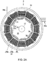
- Fig. 2A and 2B are cross-sectional views schematically illustrating a configuration of the motor 3.
- the motor 3 illustrated in Figs. 2A and 2B is disposed behind the engine 2. This motor 3 is serially coupled to the engine 2 through the first clutch 5.
- the motor 3 is a permanent-magnet type synchronous motor which is driven by three-phase alternating current.
- the motor 3 roughly includes a motor case 31, a shaft 32, a rotor 33, and a stator 34.
- the motor case 31 is comprised of a cylindrical container which defines a cylindrical space.
- the motor case 31 is fixed to the vehicle body of the automobile 1 in a state where both end faces in the axial direction are sealed.
- the rotor 33 and the stator 34 are accommodated in the motor case 31.
- the shaft 32 is rotatably supported by the motor case 31 in a state where both end parts in the axial direction project from the motor case 31.
- the first clutch 5 is installed between one end part (a front end part) of the shaft 32 and the output shaft of the engine 2.
- the first clutch 5 is switchable between a state where the output shaft and the shaft 32 are coupled to each other (a coupled state) and a state where the output shaft and the shaft 32 are decoupled from each other (a decoupled state).
- the second clutch 7 is installed between the other end part (a rear end part) of the shaft 32 and an input shaft of the transmission 8.
- the second clutch 7 is switchable between a state where the shaft 32 and the input shaft are coupled to each other (a coupled state) and a state where the shaft 32 and the input shaft are decoupled from each other (a decoupled state).
- first clutch 5 and the second clutch 7 are adjustable of the motive power transmitted through the shaft 32 in a state between the coupled state and the decoupled state (a partially-coupled state).
- the rotor 33 has magnets 35 and outputs the rotational motive force.
- the rotor 33 according to this embodiment is comprised of a cylindrical member. This cylindrical member is formed by laminating a plurality of metal plates each having an axial hole at the center, along the axial direction.
- the rotor 33 is integrated with the shaft 32 by fixing an intermediate part of the shaft 32 to the axial holes of the rotor 33.
- a plurality of magnets 35 are disposed on the outer circumferential part of the rotor 33 along the rotation direction of the rotor 33.
- the plurality of magnets 35 include first magnets 35a of which the S-poles are oriented toward the inner circumferential surface of the stator 34, and second magnets 35b adjacent to the first magnets 35a in the rotation direction, of which the N-poles are oriented toward the inner circumferential surface of the stator 34.
- the rotation direction of the rotor 33 is equivalent to the circumferential direction of the rotor 33 (i.e., the circumferential direction of the stator 34 and the motor 3).
- the term “the rotation direction of the rotor 33” as used herein is simply referred to as “the rotation direction.”
- the term “the radial direction of the rotor 33” as used herein is simply referred to as “the radial direction” in the following description.
- the first magnet 35a may also be referred to as a "S-magnet 35a.”
- the second magnet 35b may also be referred to as a "N-magnet 35b.”
- the plurality of magnets 35 are comprised of, for example in the configuration illustrated in Fig. 2A , four first magnets 35a and four second magnets 35b.
- the first magnets 35a and the second magnets 35b are alternately disposed in the rotation direction, with equal interval therebetween.
- the plurality of magnets 35 are each formed in a rectangular shape with the dimension in the rotation direction longer than the dimension in the radial direction in the cross sections illustrated in Figs. 2A and 2B (i.e., a cross section perpendicular to the shaft 32).
- the plurality of magnets 35 are each comprised of a so-called "variable magnetic-force magnet. That is, the plurality of magnets 35 are each variable in the magnetic force.
- the motor 3 of this type permanent magnets with large coercivity are used in order to maintain the magnetic force over a long period of time.
- permanent magnets with coercivity smaller than normal permanent magnets are used as the magnets 35 so that the magnetic force is comparatively easily changeable.
- magnets 35 There are various types of permanent magnets used as the magnets 35, which include ferrite magnets, neodymium magnets, samarium cobalt magnets, and Alnico magnets, with different coercivity.
- the material of the magnet 35 is selectable according to the usage, and therefore, it is not limited in particular.
- each accommodation space 37 is defined by a pair of support surfaces 37a and 37b for supporting the magnet 35.
- the pair of support surfaces 37a and 37b pinch the magnet 35 from both sides in the radial direction.
- the stator 34 has a plurality of coils 36 disposed so as to oppose the rotor 33 with a gap therebetween.
- the stator 34 according to this embodiment has a stator core 34a which is formed by laminating a plurality of metal plates, and the plurality of coils 36 which are each formed by winding an electric wire around the stator core 34a.
- the stator core 34a is provided with a plurality of teeth 34b extending radially.
- the electric wire is wound around slots, each defined between adjacent teeth 34b, in a given order.
- the plurality of coils 36 are each formed by the electric wire coiled in this way. That is, the plurality of coils 36 are each constructed as a so-called "concentrated winding coil.”
- the plurality of coils 36 constitutes three phase coil groups with different phases of current (U-phase, V-phase, W-phase) which flow therethrough. Each coil group is disposed in the order in the rotation direction. For example, in the configuration illustrated in Fig. 2A , the plurality of coils 36 are comprised of the total of twelve coils 36. The twelve coils 36 is classified into a U-phase coil group comprised of four coils 36, a V-phase coil group comprised of four coils 36, and a W-phase coil group comprised of four coils 36.
- the coils 36 belonging to the U-phase coil group may be referred to as “U-phase coils 36u”
- the coils 36 belonging to the V-phase coil group may be referred to as “V-phase coils 36v”
- the coils 36 belonging to the W-phase coil group may be referred to as “W-phase coils 36w” (see Fig. 2B , etc.)
- the eight-pole twelve-slot motor 3 is illustrated, the configuration of the motor 3 is not limited to this example.
- the motor 3 may have a larger number of poles and a larger number of slots.
- the motor 3 may be comprised of 2xN magnets 35 and 3xN slots (here, N is an integer).
- the three connecting cables 36a are connected to these coils 36.
- the three connecting cables 36a are comprised of a connecting cable 36a connected to the U-phase coil group, a connecting cable 36a connected to the V-phase coil group, and the connecting cable 36a connected to the W-phase coil group.
- These connecting cables 36a are drawn outside the motor case 31 and connected with the battery 10 through the inverter 6.
- the battery 10 according to this embodiment is not a high-voltage battery like those mounted on the conventional hybrid vehicle. Therefore, the battery 10 can be reduced in the weight and size. Moreover, since the advanced electric-shock countermeasures are not necessary, insulating members, etc. can also be simplified. By this simplification, the battery 10 can further be reduced in the weight and size. Thus, since the weight of the automobile 1 can be reduced, fuel efficiency and power efficiency can be improved.
- the battery 10 supplies direct current to the inverter 6.
- the inverter 6 converts the direct current into alternating current of three phases comprised of U-phase, V-phase, and W-phase.
- the inverter 6 supplies the alternating current converted into the U-phase to the U-phase coil group, supplies the alternating current converted into the V-phase to the V-phase coil group, and supplies the alternating current converted into the W-phase to the W-phase coil group.
- the coils 36 which constitute the coil groups By the supply of the alternating current, the coils 36 which constitute the coil groups generate a magnetic field. Then, the coils 36 which generated the magnetic field attract or repulse the magnets 35 to rotate the rotor 33. The rotated rotor 33 outputs the rotational motive force through the shaft 32. This rotational motive force is inputted into the transmission 8 through the shaft 32 and the second clutch 7.
- the transmission 8 is a multiple-speed automatic transmission (a so-called "AT").
- the transmission 8 has an input shaft at one end and has an output shaft at the other end.
- a transmission mechanism including a plurality of planetary gear mechanisms, clutches, and brakes, are incorporated between the input shaft and the output shaft. By switching such a transmission mechanism, forward and reverse of the automobile 1 can be switched, and rotational speeds of the input shaft and the output shaft of the transmission 8 can be changed.
- the output shaft of the transmission 8 extends in the front-and-rear direction of the vehicle body.
- the output shaft is coupled to the differential gear 9 through a propeller shaft 11 disposed coaxially with the output shaft.
- the differential gear 9 is coupled to a pair of drive shafts 13.
- the pair of drive shafts 13 extend in the vehicle width direction, and are coupled to the left and right driving wheels 4R.
- the rotational motive force outputted through the propeller shaft 11 is distributed to each drive shaft 13 by the differential gear 9, and the distributed forces are then transmitted to the driving wheels 4R through the corresponding drive shafts 13.
- a brake 14 for braking the rotation is attached to each of the wheels 4F and 4R.
- the motor 3 is provided with two kinds of sensors 55 and 56 in order to determine a temperature of the magnets 35 which constitute the rotor 33 (hereinafter, simply referred to as "the magnet temperature").
- the two kinds of sensors 55 and 56 are comprised of the search coil 55 and the voltage sensor 56 (see Fig. 3 ). These sensors 55 and 56 are both capable of detecting the induced voltage caused by the rotation of the rotor 33.
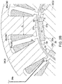
- the search coil 55 is formed by superimposing an electric wire on any one of the plurality of coils 36, as illustrated in Fig. 2B .
- the search coil 55 is coaxial with the coil 36 on which the electric wire is superimposed.
- the search coil 55 is connected to the MCU 21 through a search connecting cable 36b.
- the search connecting cable 36b is electrically separated from the three connecting cables 36a which lead to the inverter 6. That is, the search connecting cable 36b is connected to a circuit which is independent from the inverter 6 for driving the motor 3.
- the search coil 55 detects the induced voltage which is induced by the magnets 35 passing through the coil 36 where the search coil 55 is formed, when rotating the rotor 33, and then inputs the detection signal into the MCU 21.
- the voltage sensor 56 detects a voltage between a neutral point of the motor 3 and each of the connecting cables 36a and then inputs the detection signals into the MCU 21.
- the motor 3 illustrated in Fig. 1 , etc. is provided with a feature part which is suitable for detecting the induced voltage by the search coil 55 and the voltage sensor 56.
- apertures 38 adjacent to each magnet 35 in the rotation direction are formed in the rotor 33 according to this embodiment.
- the apertures 38 are disposed adj acent to both ends of the magnet 35 in the rotation direction.
- Each aperture 38 functions as a so-called "flux barrier.” That is, the aperture 38 suppresses the magnetic flux of a certain magnet 35 from turning around other magnets 35 inside the rotor 33. Therefore, the magnetic flux which crosses the stator 33 through the aperture can be increased.
- each aperture 38 extends in the rotation direction so as to separate from the corresponding magnet 35.
- the dimension of each aperture 38 in the rotation direction is defined based on the dimension of the coil 36.
- D 1 defines a lower limit of the dimension of the aperture 38 in the rotation direction.
- D 3 defines an upper limit of the dimension of the aperture 38 in the rotation direction.
- the dimension of the aperture 38 in the radial direction decreases along the rotation direction away from the magnet 35. That is, the aperture 38 is tapered as illustrated in Fig. 2B . As illustrated in this drawing, tip-end parts of the adjacent apertures 38 face each other in the rotation direction.
- the apertures 38 communicate with the accommodation space 37 of the corresponding magnet 35 in the rotor 33.
- the radially-outward support surface 37a among the support surfaces 37a and 37b which define the accommodation space 37 is connected flush with the inner circumferential surfaces of the apertures 38.
- the radially-inward support surface 37b is connected with the inner circumferential surfaces of the apertures 38 through a stepped part.
- the automobile 1 includes, in order to control its traveling, the ECU 20, the MCU 21, the TCU 22, the BCU 23, and the GCU 24, which are described above.
- the ECU 20 is a unit that mainly controls operation of the engine 2.
- the MCU 21 is a unit that mainly controls operation of the motor 3.
- the TCU 22 is a unit that mainly controls operation of the first clutch 5, the second clutch 7, and the transmission 8.
- the BCU 23 is a unit that mainly controls operation of the brake 14.
- the GCU 24 is electrically connected to the ECU 20, the MCU 21, the TCU 22, and the BCU 23, and is a host unit which comprehensively controls these units.
- the MCU 21 among these units constitutes a "motor control device.”
- the MCU 21 is one example of a controller.
- the MCU 21 includes a microprocessor 211, memory 212, and an interface (I/F) circuit 213.
- the microprocessor 211 executes a program.
- the memory 212 stores the program and data.
- the memory 212 is, for example, RAM (Random Access Memory) and ROM (Read Only Memory).
- the I/F circuit 213 outputs and inputs an electrical signal.
- each unit other than the MCU 21 constitutes "the motor control device” by collaborating with the MCU 21.
- Each unit is provided with a microprocessor (not illustrated), memory (not illustrated), and an I/F circuit (not illustrated), similar to the MCU 21.
- the MCU 21 is connected to the search coil 55 and the voltage sensor 56 as sensors. Detection signals of the search coil 55 and the voltage sensor 56 are inputted into the MCU 21. Sensors other than the search coil 55 and the voltage sensor 56, which are relevant to the traveling of the automobile 1, may be the following sensors 50-54.
- the engine speed sensor 50 detects an engine speed of the engine 2 and inputs it into the ECU 20.
- the engine speed sensor 50 is attached to the engine 2.
- the motor rotation sensor 51 detects a rotational speed and a rotational position of the rotor 33 and inputs them into the MCU 21.
- the motor rotation sensor 51 is attached to the motor 3.
- the current sensor 52 detects a value of current supplied to each coil 36 and inputs them into the MCU 21.
- the current sensor 52 is attached to the connecting cable 36a.
- the magnetic sensor 53 detects a magnetic field caused by the magnet 35 and inputs a signal indicative of the strength into the MCU 21.
- the magnetic sensor 53 is attached to the motor 3.
- the accelerator sensor 54 detects an accelerator opening corresponding to an output required for propelling the automobile 1 and inputs a signal indicative of the magnitude into the ECU 20.
- the accelerator sensor 54 is attached to an accelerator pedal 15 which is stepped on when a vehicle operator drives the automobile 1.
- the automobile 1 travels by the units collaboratively controlling the drive system based on the detection signals inputted from these sensors.
- the ECU 20 controls the operation of the engine 2 based on the detection signals from the accelerator sensor 54 and the engine speed sensor 50.
- the TCU 22 controls the first clutch 5 and the second clutch 7 so that they become in the coupled state.
- the BCU 23 controls each brake 14.
- the TCU 22 controls the first clutch 5 so that it becomes in the decoupled state or the partially-coupled state, and controls the second clutch 7 so that it becomes in the coupled state.
- the MCU 21 controls so that the motor 3 generates electric power and the regenerated electric power is collected by the battery 10.
- the MCU 21 controls the motor 3 by supplying power to the plurality of coils 36.
- the MCU 21 controls so that the automobile 1 travels by the rotational motive force of the motor 3 in a state where the motor 3 solely outputs the rotational motive force, or in a state where the motor 3 assists the drive of the engine 2.
- the ECU 20 sets the rotational motive force of the engine 2 based on the detected values of the accelerator sensor 54 and the engine speed sensor 50. Then, the GCU 24 sets a demanded amount of the rotational motive force of the motor 3 so that it falls within a given output range, according to a given distribution ratio of the outputs of the engine 2 and the motor 3.
- the MCU 21 controls the motor 3 by the three-phase alternating current which flows into the motor 3 so that the demanded amount is outputted.
- the MCU 21 controls a torque current component in the three-phase alternating current to change torque generated in the rotor 33. Therefore, the motor 3 outputs the demanded amount of the rotational motive force.
- the MCU 21 also controls a magnetizing current component in the three-phase alternating current to change the magnetic field strength generated in the coil 36. Although the details are omitted, the magnetic field strength generated by the magnets 35 (the magnetic force of the magnets 35) can be changed by changing the magnetic field strength generated in the coil 36. In detail, the magnetic force of the magnet 35 is changed so as to be substantially in agreement with the magnetic field strength generated in the coil 36 by the driving current.
- the MCU 21 can perform an estimation of the magnet temperature and a motor control based on the magnet temperature, according to given control logic.
- control logic for estimating the magnet temperature is described in detail.
- the MCU 21 can execute two kinds of estimation logic solely or in combination. That is, the MCU 21 constitutes a "motor magnet temperature estimating device."
- the configuration of the MCU 21 as the motor magnet temperature estimating device is as illustrated in Fig. 4 .
- a first estimation logic among the two kinds of estimation logic is control logic focusing on a timing at which the induced voltage becomes flat. Moreover, a second estimation logic is control logic focusing on a harmonic content of the induced voltage.
- the two kinds of estimation logic are stored in the memory 212.
- the first estimation logic may not necessarily be essential.
- Fig. 5 is a graph illustrating the induced voltage caused in the coil 36.
- Fig. 6 is a graph illustrating relationships between an aperture area, and a voltage stability and a mechanical strength.
- the first estimation logic is described with reference to Figs. 5 and 6 .
- a graph G1 of Fig. 5 illustrates temporal changes in an induced voltage Vu caused in the U-phase coil 36u, an induced voltage Vv caused in the V-phase coil 36v, and an induced voltage Vw caused in the W-phase coil 36w.
- the induced voltage Vu caused in the U-phase coil 36u is described as one example.
- the induced voltage Vu is detected by superimposing the search coil 55 on one of the four U-phase coils 36u and monitoring the voltage of the search coil 55.
- the following description is similar to the V-phase coil 36v and the W-phase coil 36w.
- the magnetic flux which pierces through the S-magnet 35a among the magnetic flux which is generated by the S-magnet (first magnet) 35a is directed radially inward (see an arrow As).
- the magnetic flux which pierces through the N-magnet 35b among the magnetic flux which is generated by the N-magnet (second magnet) 35b is directed radially outward (see an arrow An).
- the magnitude of the induced voltage Vu is proportional to a temporal change in the magnetic flux which crosses the U-phase coil 36u. Therefore, the induced voltage Vu reaches a peak at a timing where the temporal change in the magnetic flux becomes the maximum.
- the timing at which the temporal change in the magnetic flux becomes the maximum is equal to a timing at which a location of the outer circumferential part of the rotor 33 which is located at a midpoint of the S-magnet 35a and the N-magnet 35b crosses a center axis line Lc of the U-phase coil 36u (see an enclosed part C2 of Fig. 5 ).
- This timing is equivalent to a timing at which the direction of the magnetic flux which crosses the U-phase coil 36u is inverted.
- the temporal change in the magnetic flux becomes the minimum or becomes as small as possible the temporal change in the induced voltage Vu can be reduced as much as possible.
- the temporal change in the induced voltage Vu becomes the minimum (see enclosed parts C1 and C3 of Fig. 5 ).
- the temporal change in the induced voltage Vu becomes the minimum.
- the induced voltage Vu becomes substantially flat in the enclosed parts C1 and C3.
- the induced voltage Vu which is mainly caused by the magnetic flux of the N-magnet 35b becomes flat.
- the induced voltage Vu which is mainly caused by the magnetic flux of the S-magnet 35a becomes flat.
- the shoulder of the induced voltage is referred to as "the shoulder of the induced voltage.”
- the temporal change in the shoulder of the induced voltage Vu becomes flatter by providing the apertures 38 in the rotor 33.
- This phenomenon occurs by the apertures 38 functioning as the flux barriers, which reduces a leakage of the magnetic flux from the end parts of the magnet 35 which opposes the U-phase coil 36u to stabilize a change in the amount of magnetic flux in the end parts, and suppresses a turning around of the magnetic flux from other magnets 35 adjacent to the magnet 35 which opposes the U-phase coil 36u.
- a graph G2 in the upper portion of Fig. 6 illustrates a relationship between the aperture area and the voltage stability.
- a graph G3 in the lower portion of Fig. 6 illustrates a relationship between the aperture area and the voltage stability.
- aperture area means a cross-sectional area of each aperture 38 in a cross section perpendicular to the shaft 32 (i.e., the cross section illustrated in Fig. 2B ).
- voltage stability means a magnitude of the temporal change in the induced voltage Vu. The voltage stability becomes lower as the temporal change in the induced voltage Vu increases.
- mechanical strength means a mechanical strength of the rotor 33.
- the voltage stability becomes higher as the aperture area increases.
- the mechanical strength becomes lower as the aperture area increases.
- the voltage stability and the mechanical strength are both improved by setting the aperture area so as to fall within a given range R1.
- a dimension D 1 of the aperture 38 satisfies Formula (C) described above.
- the present inventors established the first estimation logic as follows.
- the MCU 21 estimates the magnet temperature based on the induced voltage Vu detected when the magnet 35 opposes any one of the plurality of coils 36 according to the rotation of the rotor 33.
- the MCU 21 detects the shoulder of the induced voltage Vu through the search coil 55. Detecting the shoulder of the induced voltage Vu is equivalent to detecting the induced voltage Vu at the timing where the temporal change becomes the minimum.
- the combination of detecting the shoulder of the induced voltage Vu and functioning the apertures 38 as the flux barriers can suppress the temporal change as much as possible when detecting the induced voltage Vu. Therefore, the detection accuracy of the induced voltage Vu can be improved.
- the MCU 21 estimates the magnet temperature based on the induced voltage Vu detected in this way.
- the induced voltage Vu and a density of the magnetic flux caused by the magnet 35 are in a proportional relationship.
- the magnetic flux density of the magnet 35 and the magnet temperature are in a linear relationship. Therefore, the magnet temperature can be calculated through the magnetic flux density by detecting the induced voltage Vu.
- the memory 212 of the MCU 21 stores a table indicative of a relation between the magnetic flux density and the magnet temperature. Therefore, the MCU 21 can estimate the magnet temperature by calculating the magnetic flux density based on the induced voltage Vu, and using the calculated magnetic flux density and the table stored in the memory 212. By estimating the magnet temperature in the state where the detection accuracy of the induced voltage Vu is improved, the magnet temperature can be estimated with sufficient accuracy.
- the memory 212 of the MCU 21 stores a timing (minimum timing) at which the center part of the magnet 35 in the rotation direction crosses the center axis line Lc of each of the plurality of coils 36, and the MCU 21 acquires the induced voltage Vu at the minimum timing.
- the minimum timing is equivalent to a timing at which the temporal change in the induced voltage Vu becomes minimum. Therefore, the detection of the induced voltage Vu at the minimum timing is effective to improve the detection accuracy.
- by storing the minimum timing in advance it is possible to more securely suppress the temporal change in the induced voltage Vu, and, as a result, it is advantageous for estimating the magnet temperature with sufficient accuracy.
- the detection of the induced voltage Vu by the MCU 21 is not performed only at the minimum timing, but it may also be performed over a given period Ts including the minimum timing.
- the MCU 21 acquires the induced voltage Vu over the given period Ts including the minimum timing to estimate the magnet temperature based on an average value of the induced voltages Vu acquired over the given period Ts.
- the average value instead of the induced voltage Vu detected at the specific timing, it can suppress the effect of the temporal change in the induced voltage Vu as much as possible, and can reduce the effect of the variation in the induced voltage Vu resulting from noise, etc. This becomes advantageous when estimating the magnet temperature with sufficient accuracy.
- the given period Ts is set so as not to include the timing at which the induced voltage Vu reaches the peak. That is, the given period Ts is set as a period which does not include the timing at which the part located at the midpoint of the two adjacent magnets 35 in the rotation direction crosses the center axis line Lc of the coil 36.
- the MCU 21 estimates the magnet temperature, not based on the induced voltage caused in the coils 36 used for driving the motor 3, but based on the induced voltage Vu caused in the search coil 55 which is superimposed with one of these coils 36.
- the search coil 55 it is possible to indirectly detect the induced voltage caused in the coil 36 on which the search coil 55 is superimposed.
- the temperature of each magnet 35 which passes through the search coil 55 can be estimated individually, and, as a result, the magnet temperature can be determined more accurately. As will be described later, the accurate determination of the magnet temperature becomes particularly effective when performing the motor control based on the magnet temperature.
- an effective value, an average value, and a maximum value of the induced voltage Vu may be used, or like the second estimation logic, the lowest order higher harmonic wave when the induced voltage Vu is divided into a frequency component may be used.
- the temperature of the entire magnet 35 and a temperature difference between the magnets 35 can be estimated with sufficient accuracy, but they are not suitable for individually estimating the temperature of each magnet 35.
- the first estimation logic it is possible to detect the induced voltage for every magnet 35 to individually estimate the magnet temperature.
- the first estimation logic is effective in that it can individually estimate the temperature of each magnet 35 with sufficient accuracy.
- each aperture 38 is reduced in the dimension in the radial direction of the rotor 33 as it separates from the magnet 35 in the rotation direction.
- a part of the aperture 38 close to the magnet 35 is secured widely in the cross-sectional area because the dimension in the radial direction is relatively larger, it is advantageous when demonstrating the flux-barrier function.
- a part of the aperture 38 away from the magnet is shortened gradually in the radial dimension to be tapered, it is advantageous when securing the mechanical strength of the rotor 33.
- the support surface 37a which is located radially outward is connected flush with the inner circumferential surfaces of the apertures 38.
- the support surface 37a flush with the inner circumferential surfaces of the apertures 38 it is possible to connect both surfaces smoothly.
- this configuration it is possible to vary the induced voltage Vu smoothly, as compared with the configuration in which a stepped part exists between the support surface 37a and the inner circumferential surfaces of the apertures 38. Therefore, the temporal change in the induced voltage Vu is suppressed more securely, and, as a result, it is advantageous when estimating the magnet temperature with sufficient accuracy.
- Fig. 7 is a view illustrating an amplitude and a phase which are obtained by Fast Fourier Transform of the induced voltage.
- Fig. 8 is a graph illustrating a relationship between the magnetic flux density and the magnet temperature of the magnet 35.
- second estimation logic is described with reference to Figs. 7 and 8 .
- the induced voltage Vu caused in the U-phase coil 36u is described as one example.
- the induced voltage Vu is detected by monitoring an electric potential difference between the neutral point of the motor 3 and the connecting cable 36a connected to the U-phase coil 36u.
- the following description can similarly be applied to the V-phase coil 36v and the W-phase coil 36w.
- a graph G4 in the left portion of Fig. 7 illustrates the induced voltage Vu caused in the U-phase coil 36u.
- a bar graph G5 in the right portion of Fig. 7 illustrates an absolute value (amplitude) of the frequency spectrum obtained by carrying out a Fast Fourier Transform (FFT) of the induced voltage Vu.
- a line graph G6 in the right portion of Fig. 7 illustrates an angle of deviation (phase) of the frequency spectrum obtained by the FFT.
- a line graph G6' illustrated in the right portion of Fig. 7 is the same in the temperature difference between the S-magnet 35a and the N-magnet 35b as the graph G6, and illustrates a case where a magnitude relationship of the temperature is inverted between the S-magnet 35a and the N-magnet 35b from a case of the graph G6.
- a waveform of the induced voltage Vu is different from a sine wave. This originates in a spatial relationship between the magnet 35 and the coil 36 varying according to the rotation of the rotor 33, as referred when describing the first estimation logic. From other perspective, the waveform illustrated in the graph G4 may be obtained by superimposing on a sine wave (fundamental wave) having a given frequency, a frequency component (higher harmonic wave) of an integral multiple of the given frequency.
- a frequency of the fundamental wave is f0
- a frequency of the lowest order higher harmonic wave is fl
- the number of poles of the motor 3 is Np
- a motor rotational speed is Rm
- the number of magnets 35 per pole is Nm
- the lowest order higher harmonic wave becomes a secondary higher harmonic wave having a doubled frequency of the fundamental wave.
- Nm may be an integer of four or more.
- the frequency spectrum of the lowest order higher harmonic wave contains information indirectly indicating the temperature difference between the S-magnet 35a as the first magnet 35a and the N-magnet 35b as the second magnet 35b.
- the amplitude of the frequency spectrum of the lowest order higher harmonic wave is proportional to the temperature difference between the S-magnet 35a and the N-magnet 35b.
- the amplitude according to the higher harmonic wave becomes larger as the temperature difference increases.
- the amplitude illustrated in an enclosed part C4 becomes larger as the temperature difference between the S-magnet 35a and the N-magnet 35b increases.
- the phase of the frequency spectrum of the higher harmonic wave is inverted in the phase between a case where the N-magnet 35b is higher in the temperature than the S-magnet 35a and a case where the S-magnet 35a is higher in the temperature than the N-magnet 35b.
- the example in Fig. 7 illustrates the case where the S-magnet 35a is higher in the temperature than the N-magnet 35b.
- the sign of the phase of the higher harmonic wave becomes positive, as illustrated in an enclosed part C5.
- the sign of the phase at the same frequency as the enclosed part C5 is inverted and becomes negative when the N-magnet 35b is higher in the temperature than the S-magnet 35a, as illustrated in an enclosed part C5'.
- the amplitude of the frequency spectrum of the fundamental wave is relevant to the average temperature of the S-magnet 35a and the N-magnet 35b.
- the amplitude according to the fundamental wave becomes larger as the average value of the magnetic flux density of the S-magnet 35a and the N-magnet 35b increases.
- the magnetic flux density is in a linear relationship with the magnet temperature, as described above. Therefore, the possible average temperature of each magnet 35 can be estimated by using the amplitude according to the fundamental wave.
- the MCU 21 estimates the magnet temperature based on the frequency spectrum corresponding to the given frequency among the frequency components which constitute the induced voltage.
- the MCU 21 performs the FFT to the induced voltage in order to acquire the frequency spectrum corresponding to the given frequency.
- the given frequency is a frequency of the lowest order higher harmonic wave (in this embodiment, the secondary higher harmonic wave) among the n-th order higher harmonic wave (n is an integer) which is defined according to the number of magnets 35.
- the MCU 21 estimates the magnetic flux density of the magnet 35 based on the amplitude of the frequency spectrum obtained by the FFT.
- the MCU 21 adds the amplitude according to the lowest order higher harmonic wave to the amplitude according to the fundamental wave. Therefore, the maximum value of the amplitude (maximum amplitude) in consideration of the temperature difference between the magnets 35 can be calculated.
- the MCU 21 according to this embodiment is provided with a band-pass filter 57 into which the frequency spectrum obtained by the FFT is inputted.
- the configuration of the band-pass filter 57 may be changed suitably according to the frequency of the lowest order higher harmonic wave.
- the MCU 21 calculates the magnetic flux density based on the maximum amplitude obtained in this way to estimate the magnet temperature based on the magnetic flux density.
- the maximum amplitude indicates the maximum value of the induced voltage Vu in consideration of the temperature difference between the magnets 35.
- the induced voltage Vu and the magnetic flux density of the magnet 35 are in a proportional relationship as described above.
- the magnetic flux density of the magnet 35 and the magnet temperature are in a linear relationship. Therefore, the magnet temperature can be calculated through the magnetic flux density by detecting the induced voltage Vu.
- the MCU 21 can also identify a relatively hot or cold magnet 35 among the N-magnet 35b and the S-magnet 35a based on the phase of the frequency spectrum obtained by the FFT. This function is used for the motor control based on the magnet temperature (described later).
- the magnet temperature can be estimated with sufficient accuracy by using the amplitude of the frequency spectrum obtained by performing the Fourier transform to the induced voltage Vu.
- the magnet temperature may be estimated based on the induced voltage Vu detected at the specific timing, like the first estimation logic.
- a sampling frequency when carrying out an analog/digital (A/D) conversion of the induced voltage needs to be set as high as it suits the rotational speed of the motor 3. Such a method is inconvenient when the motor rotates at high speed.
- the second estimation logic can estimate the magnet temperature without detecting the induced voltage Vu at the specific timing
- the sampling frequency can be kept lower than the conventional method. It is possible to simplify the processing to the induced voltage Vu, such as filtering processing, by keeping the sampling frequency low. Moreover, the simplification of the processing to the induced voltage Vu is effective when estimating the magnet temperature more promptly or more securely.
- the relatively hot magnet 35 can be identified among the S-magnet 35a and the N-magnet 35b by using the phase of the frequency spectrum. This is effective when finely controlling the temperature of each magnet 35.
- the temperature difference of the magnets 35 can be estimated with sufficient accuracy, and the hotter magnet 35 can be identified with sufficient accuracy. This is effective when estimating the temperature of each magnet 35 more exactly.
- the magnet temperature can be estimated on the safer side.
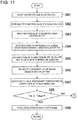
- Fig. 4 is a block diagram illustrating a configuration of the motor magnet temperature estimating device.
- the estimating device illustrated in Fig. 4 is provided with a plurality of functional blocks.
- the estimating device includes an estimating method selecting module 214 which selects either one of the first estimation logic and the second estimation logic, a first estimating module 215 which performs the first estimation logic, a second estimating module 216 which performs the second estimation logic, and a motor controlling module 217 which controls the motor 3 based on the executed result of the first estimating module 215 or the second estimating module 216.
- the estimating method selecting module 214 selects whether the first estimation logic is to be performed by the first estimating module 215 or the second estimation logic is to be performed by the second estimating module 216 based on the rotational speed of the rotor 33.
- the estimating method selecting module 214 selects, based on the detection signal from the motor rotational speed sensor 41, the first estimating module 215 if the rotational speed of the rotor 33 is below a given threshold, and the second estimating module 216 if the rotational speed of the rotor 33 is the given threshold or above.
- the estimating method selecting module 214 causes the selected one of the first estimating module 215 and the second estimating module 216 to perform the temperature estimation.
- the magnet temperature can be individually estimated with sufficient accuracy.
- the estimation of the magnet temperature by the second estimating module 216 can keep the sampling frequency lower than the conventional method, it can securely estimate the magnet temperature, even if the rotational speed of the motor 3 is high.
- the estimating method selecting module illustrated in Fig. 4 causes the first estimating module 215 to perform the temperature estimation, and, on the other hand, if the rotational speed of the motor 3 is high, it causes the second estimating module 216 to perform the temperature estimation.
- the given threshold used as a reference of the choice by the estimating method selecting module 214 is defined according to the specification of the motor 3. This given threshold is stored in the memory 212 of the MCU 21 in advance.
- the first estimating module 215 includes, as functional blocks for performing the first estimation logic, an induced voltage detecting module 21a, an average voltage calculating module 21b, a flux-density calculating module 21c, a magnet temperature estimating module 21d, and a regulating amount calculating module 21e.
- the induced voltage detecting module 21a detects the induced voltage Vu through the search coil 55.
- This induced voltage Vu is in substantially agreement with the induced voltage caused in the U-phase coil 36u on which the search coil 55 is superimposed among the total of twelve coils 36.
- the induced voltage detecting module 21a detects the induced voltage Vu through an A/D converter (not illustrated) and converts it into a digital signal.
- the induced voltage Vu converted into the digital signal by the induced voltage detecting module 21a is inputted into the average voltage calculating module 21b.
- the average voltage calculating module 21b calculates an average voltage in the shoulder described above (in detail, the given period Ts including the minimum timing) based on the induced voltage Vu inputted from the induced voltage detecting module 21a.
- the calculation of the average voltage is individually performed to both of the shoulder which originates in the N-magnet 35b (see the enclosed part C1 of Fig. 5 ) and the shoulder which originates in the S-magnet 35a (see the enclosed part C3 of Fig. 5 ).
- a range of electrical angle equivalent to the given period Ts is stored in the memory 212 in advance.
- the average voltage calculating module 21b calculates the average value of the induced voltage Vu in the given period Ts based on the range of the electrical angle stored in the memory 212 and the detection signal from the motor rotation sensor 51. The calculated average value is inputted into the flux-density calculating module 21c.
- the average value according to the N-magnet 35b is referred to as a "first voltage Vn" and the average value according to the S-magnet 35a is referred to as a "second voltage Vp.”
- the flux-density calculating module 21c calculates a magnetic flux density Bn of the N-magnet 35b and a magnetic flux density Bp of the S-magnet 35a based on the first voltage Vn and the second voltage Vp which are inputted from the average voltage calculating module 21b.
- the flux-density calculating module 21c calculates the magnetic flux densities Bn and Bp based on the following Formulas (F) and (G).
- Bn Vn / Rm ⁇ Nc ⁇ c
- Bp Vs / Rm ⁇ Nc ⁇ c
- Rm is a motor rotational speed
- Nc is the number of turns of the coil
- c is a constant.
- the motor rotational speed Rm is detected each time by the motor rotation sensor 51.
- the number of coil turns Nc and the constant c are stored in the memory 212 in advance, and are read when calculating the magnetic flux densities Bn and Bp.
- the magnetic flux densities Bn and Bp estimated by the flux-density calculating module 21c are inputted into the magnet temperature estimating module 21d.
- the magnet temperature estimating module 21d estimates a magnet temperature Tp of the S-magnet 35a and a magnet temperature Tn of the N-magnet 35b based on the magnetic flux densities Bn and Bp estimated by the flux-density calculating module 21c.
- the magnet temperature estimating module 21d reads a table corresponding to the graph G7 of Fig. 8 from the memory 212 to estimate the magnet temperatures Tp and Tn by comparing the magnetic flux densities Bn and Bp with the table.
- the magnet temperatures Tn and Tp estimated by the magnet temperature estimating module 21d are inputted into the regulating amount calculating module 21e.
- the regulating amount calculating module 21e determines a temperature state of each of the magnets 35a and 35b based on the magnet temperatures Tn and Tp estimated by the magnet temperature estimating module 21d. If the temperature state is determined to be abnormal, the regulating amount calculating module 21e calculates a motor regulating amount Pm for regulating the output of the motor 3.
- the regulating amount calculating module 21e compares each of the magnet temperatures Tn and Tp with an upper limit temperature Tmax set in advance. If the magnet temperature Tn according to the N-magnet 35b and the magnet temperature Tp according to the S-magnet 35a both exceed the upper limit temperature Tmax, the regulating amount calculating module 21e determines that the temperature state of the magnet 35 is abnormal.
- the constant K is stored in the memory 212 in advance, and is read when calculating the power regulating amount.
- the power regulating amount calculated by the regulating amount calculating module 21e is inputted into the motor controlling module 217.
- the regulating amount calculating module 21e determines that the temperature state of the magnet 35 is normal. In this case, the calculation of the power regulating amount is not performed.
- the second estimating module 216 includes, as functional blocks for performing the second estimation logic, an induced voltage detecting module 21f, an FFT executing module 21g, a temperature variation calculating module 21h, a flux-density calculating module 21i, a magnet temperature estimating module 21j, and a regulating amount calculating module 21k.
- the induced voltage detecting module 21f detects the induced voltage Vu through the voltage sensor 56.
- This induced voltage Vu is substantially in agreement with the induced voltage caused in the four U-phase coils 36u among the total of twelve coils 36.
- the induced voltage detecting module 21a detects the induced voltage Vu through the A/D converter (not illustrated) and converts it into a digital signal.
- the induced voltage Vu converted into the digital signal by the induced voltage detecting module 21f is inputted into the average voltage calculating module 21b.
- the FFT executing module 21g performs an FFT to the induced voltage Vu inputted from the induced voltage detecting module 21f, and converts the induced voltage Vu into a frequency spectrum. In detail, the FFT executing module 21g performs the FFT to data over N periods among the induced voltage Vu. Note that the term "N periods" as used herein refers to a range where the motor rotational speed does not change much. The value of N may be stored in the memory 212 in advance, or may be calculated each time based on the detection signal from the motor rotation sensor 51.
- the FFT executing module 21g applies the FFT to the induced voltage Vu to obtain a frequency spectrum which is transformed in variables from the actual time to the frequency.
- the frequency spectrum obtained by the FFT executing module 21g is comprised of an absolute value (amplitude) of the frequency spectrum, and an angle of deviation (phase) of the frequency spectrum.
- the FFT executing module 21g filters the obtained frequency spectrum by using the band-pass filter 57. Through the filtering, the FFT executing module 21g derives at least an amplitude Fa of the fundamental wave, and an amplitude Fb and the phase Pb of the lowest order higher harmonic wave, and then inputs them into the temperature variation calculating module 21h.
- the temperature variation calculating module 21h calculates the maximum amplitude Fmax by adding the amplitude Fb of the lowest order higher harmonic wave to the amplitude Fa of the fundamental wave.
- the maximum amplitude Fmax calculated by the temperature variation calculating module 21h is inputted into the flux-density calculating module 21i.
- the arguments Rm, Nc, and c are the same as the above Formulas (J) and (G).
- the magnetic flux density Bm estimated by the flux-density calculating module 21i is inputted into the magnet temperature estimating module 21j.
- the magnet temperature estimating module 21j estimates the magnet temperature Tm of each magnet 35 based on the magnetic flux density Bm estimated by the flux-density calculating module 21i.
- the magnet temperature estimating module 21j reads a table corresponding to the graph G7 of Fig. 8 from the memory 212 to estimate the magnet temperature Tm by comparing the magnetic flux density Bm with the table.
- the magnet temperature Tm estimated by the magnet temperature estimating module 21j is inputted into the regulating amount calculating module 21k.
- the regulating amount calculating module 21k determines a temperature state of each magnet 35 based on the magnet temperature Tm estimated by the magnet temperature estimating module 21j.
- the regulating amount calculating module 21k calculates a motor regulating amount Pm for regulating the output of the motor 3 when the temperature state is determined to be abnormal.
- the regulating amount calculating module 21k compares the magnet temperature Tm with the upper limit temperature Tmax set in advance. If the magnet temperature Tm exceeds the upper limit temperature Tmax, the regulating amount calculating module 21k determines that the temperature state of the magnet 35 is abnormal.
- the constant K2 is stored in the memory 212 in advance, and is read when calculating the power regulating amount.
- the power regulating amount calculated by the regulating amount calculating module 21k is inputted into the motor controlling module 217.
- the regulating amount calculating module 21k determines that the temperature state of the magnet 35 is normal. In this case, the calculation of the power regulating amount is not performed.
- the motor controlling module 217 performs a control based on the power regulating amount calculated by the first estimating module 215 or the second estimating module 216. In detail, the motor controlling module 217 compares the power regulating amount with the demanded output of the motor 3, and determines whether the demanded output exceeds the power regulating amount.
- the motor controlling module 217 drives the motor 3 through the inverter 6, while performing a high-temperature measure control for addressing the temperature abnormality of the magnet 35.
- the motor controlling module 217 determines that the countermeasure to the temperature abnormality of the magnet 35 is not necessary, and drives the motor 3 through the inverter 6, as usual.
- the motor controlling module 217 regulates the output of the motor 3 by regulating the acceleration of the automobile 1 or regulating a charged amount of the battery 10, as the high-temperature measure control.
- the motor controlling module 217 may increase an amount of cooling of the motor 3 by increasing a flow rate of coolant or performing forcible air cooling.
- the motor controlling module 217 may suppress a generation of the Joule's heat resulting from eddy current by modulating the alternating current supplied to the coils 36.
- Fig. 9 is a flowchart illustrating processing relevant to the first and second estimation controls.
- Fig. 10 is a flowchart illustrating the estimation procedure of the magnet temperature by the first estimating module 215
- Fig. 11 is a flowchart illustrating the estimation procedure of the magnet temperature by the second estimating module 216.
- Step S1 of Fig. 9 the MCU 21 determines whether the demand torque of the motor 3 is zero. This determination is performed based on the detection signal from the various sensors, such as the accelerator sensor 54. The situation where the demand torque of the motor 3 is zero corresponds to a state where an acceleration or a deceleration of the automobile 1 is not demanded, a state where the power generation of the motor 3 is not demanded, etc. If the determination at Step S1 is NO, the control process shifts to Step S8. On the other hand, if the determination at Step S1 is YES, the control process shifts to Step S2.
- the MCU 21 suspends switching of the inverter 6.
- the MCU 21 suspends an on-off control of a switching element inside the inverter 6.
- the MCU 21 reads the detection signals from the various sensors.
- the detection signal read at Step S3 includes at least the detection signal from the motor rotation sensor 51.
- Step S4 the estimating method selecting module 214 in the MCU 21 determines whether the rotational speed of the motor 3 is at or above the given threshold. If above the given threshold, the estimating method selecting module 214 shifts to Step S5, and, on the other hand, if below the given threshold, it shifts to Step S6.
- the first estimating module 215 performs the control based on the first estimation logic (first estimation control) to estimate the magnet temperature.
- the second estimating module 216 performs the control based on the second estimation logic (second estimation control) to estimate the magnet temperature.
- Fig. 10 is a flowchart illustrating the detail of Step S5 in Fig. 9 . That is, Steps S51 to S58 of Fig. 10 constitute Step S5 of Fig. 9 .
- the induced voltage Vu caused in the U-phase coil 36u is inputted into the induced voltage detecting module 21a.
- the induced voltage Vu inputted into the induced voltage detecting module 21a is equivalent to the induced voltage Vu detected by the search coil 55.
- the average voltage calculating module 21b averages the voltage value in the shoulder of the induced voltage Vu before the peak (i.e., the shoulder which originates in the N-magnet 35b), and sets it as a first voltage Vn.
- the shoulder here is equivalent to the given period Ts described above. This given period Ts may be, for example, the electrical angle of 40° or more and 50° or less.
- the average voltage calculating module 21b averages the voltage value in the shoulder of the induced voltage Vu after the peak (i.e., the shoulder which originates in the S-magnet 35a), and sets it as a second voltage Vp.
- the given period Ts equivalent to the shoulder after the peak may be, for example, the electrical angle of 130° or more and 140° or less.
- the flux-density calculating module 21c calculates the magnetic flux density Bn of the N-magnet 35b based on the first voltage Vn.
- the calculation of the magnetic flux density Bn is performed based on Formula (F) described above.
- the flux-density calculating module 21c calculates the magnetic flux density Bp of the S-magnet 35a based on the second voltage Vp.
- the calculation of the magnetic flux density Bp is performed based on Formula (G) described above.
- the magnet temperature estimating module 21d compares the magnetic flux densities Bn and Bp of the N-magnet 35b and the S-magnet 35a with the table stored in the memory 212, and reads the magnet temperature Tn corresponding to the magnetic flux density Bn of the N-magnet 35b and the magnet temperature Tp corresponding to the magnetic flux density Bp of the S-magnet 35a.
- Step S57 the regulating amount calculating module 21e compares the magnet temperature Tn of the N-magnet 35b with the upper limit temperature Tmax, and compares the magnet temperature Tp of the S-magnet 35a with the upper limit temperature Tmax. Then, if the two magnet temperatures Tn and Tp are both higher than the upper limit temperature Tmax, the regulating amount calculating module 21e shifts to Step S58. On the other hand, if one of the two magnet temperature Tn and Tp is at or below the upper limit temperature Tmax, the regulating amount calculating module 21e skips Step S58 and returns to Step S7.
- Step S58 the regulating amount calculating module 21e calculates the power regulating amount by using Formula (H) described above, and returns to Step S7. That is, the control process returns from the flow illustrated in Fig. 10 and shifts to Step S7 of Fig. 9 .
- Fig. 11 is a flowchart illustrating the detail of Step S6 in Fig. 9 . That is, Steps S61 to S69 of Fig. 11 constitute Step S6 of Fig. 9 .
- the induced voltage Vu caused in the U-phase coil 36u is inputted into the induced voltage detecting module 21f.
- the induced voltage Vu inputted into the induced voltage detecting module 21a is equivalent to the induced voltage Vu detected by the voltage sensor 56.
- the FFT executing module 21g performs the FFT to the N-period data of the induced voltage Vu.
- the N periods refers to the period during which the motor rotational speed does not change much.
- the FFT executing module 21g filters the frequency spectrum obtained by the FFT with the band-pass filter 57 to output the amplitude Fa of the fundamental wave, and the amplitude Fb and the phase Pb of the lowest order higher harmonic wave.
- the temperature variation calculating module 21h reads the amplitude Fa of the fundamental wave which is obtained by the FFT. Then, at Step S64, the temperature variation calculating module 21h reads the amplitude Fb and the phase Pb of the lowest order higher harmonic wave which are obtained by the FFT.
- the temperature variation calculating module 21h calculates the maximum amplitude Fmax corresponding to the maximum value of the temperature variation by adding the amplitude Fb of the lowest order higher harmonic wave to the amplitude Fa of the fundamental wave.
- the flux-density calculating module 21i calculates the magnetic flux density Bm of the magnet 35 based on the maximum amplitude Fmax.
- the calculation of the magnetic flux density Bm is performed based on Formula (J) described above.
- the magnet temperature estimating module 21j compares the magnetic flux density Bm of the magnet 35 with the table stored in the memory 212, and reads the magnet temperature Tm corresponding to the magnetic flux density Bm.
- Step S68 the regulating amount calculating module 21k compares the magnet temperature Tm with the upper limit temperature Tmax. Then, if the magnet temperature Tm is higher than the upper limit temperature Tmax, the regulating amount calculating module 21k shifts to Step S69. On the other hand, if the magnet temperature Tm is at or below the upper limit temperature Tmax, the regulating amount calculating module 21k skips Step S69, and returns to Step S7.
- the regulating amount calculating module 21k calculates the power regulating amount based on Formula (K) described above, and returns to Step S7. That is, the control process returns from the flow illustrated in Fig. 11 and shifts to Step S7 of Fig. 9 .
- the MCU 21 suspends the switching of the inverter 6 at Step S7 after Steps S5 and S6, In detail, the MCU 21 starts the on-off control of the switching element inside the inverter 6.
- Step S8 the motor controlling module 217 determines whether the demanded output of the motor 3 exceeds the power regulating amount. If this determination is YES, the control process shifts to Step S9, and, on the other hand, if NO, the control process skips Step S9 and ends this process.
- the MCU 21 performs the high-temperature measure control described above.
- the high-temperature measure control it is possible, for example, to regulate the output of the motor 3, to increase the amount of cooling of the motor 3, and to suppress the generation of the Joule's heat resulting from the eddy current.
- the first estimating module 215 performs the first estimation logic based on the detection signal from the search coil 55
- the present disclosure is not limited to this configuration.
- the first estimating module 215 may perform the first estimation logic based on the detection signal from the voltage sensor 56.
- the second estimating module 216 performs the second estimation logic based on the detection signal from the voltage sensor 56, the present disclosure is not limited to this configuration.
- the second estimating module 216 may perform the second estimation logic based on the detection signal from the search coil 55.
Abstract
Description
- The art disclosed herein relates to a magnet temperature estimating device for a motor, and a hybrid vehicle provided with the same. The technology disclosed herein also relates to a method of estimating a magnet temperature.
-
JP2007-336708A JP2007-336708A - Moreover,
WO2014/167690A1 discloses, as another example of the magnet temperature estimating devices for motors, a cooling control device for a motor of an electric vehicle. In detail, the device disclosed inWO2014/l67690A1 - Meanwhile, when magnets which constitute a rotor of the motor become excessively high in temperature, they become irreversibly demagnetized. Therefore, in order to maintain the performance of the motor, it is necessary to reduce the magnet temperature when the magnets become high in temperature. In order to reduce the magnet temperature more securely, it is considered to estimate the magnet temperature more promptly.
- Here, as a method of estimating the magnet temperature, it is possible to use the induced voltage which is caused by driving the motor, as disclosed in
WO2014/167690A1 . Further, in order to promptly estimate the magnet temperature as described above, it is required to simplify the processing to the induced voltage as much as possible. - Therefore, the art disclosed herein is made in view of the above situations, and one purpose thereof is to simplify processing to an induced voltage when estimating a magnet temperature.
- The present disclosure relates to a magnet temperature estimating device for a motor, provided with a rotor having magnets and configured to output a rotational motive force, and a stator having a plurality of coils opposing the rotor with a gap therebetween.
- According to a first aspect of the present disclosure, the magnet temperature estimating device for the motor includes a sensor configured to detect an induced voltage induced by rotation of the rotor, and a controller configured to control the motor by supplying power to the plurality of coils in response to an input of a detection signal from the sensor. The controller estimates a temperature of one of the magnets based on amplitude of a frequency spectrum corresponding to a given frequency, among frequency components constituting the induced voltage.
- Here, the "induced voltage" means the induced electromotive force caused by magnetic flux which is generated from the one magnet.
- The magnet temperature can be estimated with sufficient accuracy by using the amplitude of the frequency spectrum obtained by performing a Fourier transform to the induced voltage.
- Meanwhile, as a method of obtaining the magnet temperature based on the induced voltage, the magnet temperature may be estimated based on the induced voltage detected at a specific timing. However, in order to use this method, a sampling frequency when carrying out an analog/digital (A/D) conversion of the induced voltage needs to be set as high as suits the rotational speed of the motor. Such a method is inconvenient when the motor rotates at high speed.
- On the other hand, according to this configuration, the magnet temperature can be estimated without detecting the induced voltage at the specific timing, and the sampling frequency can be kept lower than the conventional method. It is possible to simplify the processing to the induced voltage by keeping the sampling frequency low. Moreover, the simplification of the processing to the induced voltage is effective when estimating the magnet temperature more promptly or more securely.
- According to a second aspect of the present disclosure, the magnets may include a first magnet of which the S-pole is oriented toward the stator, and a second magnet adjacent to the first magnet in the rotation direction of the rotor and of which the N-pole is oriented toward the stator. The controller may estimate a temperature difference between the adjacent first and second magnets based on the amplitude of the frequency spectrum, and estimate the temperature of the one magnet based on the temperature difference.
- By using the amplitude of the frequency spectrum corresponding to the given frequency, the temperature difference between the first magnet and the second magnet can be estimated, which leads to estimating the magnet temperature with sufficient accuracy. Moreover, by using this method, it becomes possible to determine whether a temperature difference between the first magnet and the second magnet exists. This is effective when finely controlling the temperature of each magnet.
- According to a third aspect of the present disclosure, the amplitude of the frequency spectrum may have a linear relationship to the temperature of the one magnet. The controller may store the linear relationship in advance.
- According to this configuration, since the relationship of the amplitude of the frequency spectrum to the temperature of the one magnet is stored in advance, it is effective when estimating the magnet temperature more quickly.
- According to a fourth aspect of the present disclosure, the controller may identify a relatively hot or cold magnet among the magnets based on the phase of the frequency spectrum.
- By using the phase of the frequency spectrum corresponding to the given frequency, the relatively hotter magnet between the first magnet and the second magnet can be identified with sufficient accuracy. This is effective when finely controlling the temperature of each magnet.
- According to a fifth aspect of the present disclosure, the given frequency may be a frequency of the lowest order higher harmonic wave among higher harmonic waves defined according to the number of magnets.
- According to this configuration, by using the amplitude and phase of the lowest order higher harmonic wave, the temperature difference between the magnets can be estimated with sufficient accuracy, and the hotter magnet can be identified with sufficient accuracy. This is effective when estimating the temperature of each magnet more exactly.
- According to a sixth aspect of the present disclosure, the controller may define amplitude of the lowest order higher harmonic wave and amplitude of a fundamental wave, among the frequency components constituting the induced voltage. The controller may add the amplitude of the lowest order higher harmonic wave to the amplitude of the fundamental wave, and estimate the temperature of the one magnet based on the addition or a sum.
- According to this configuration, by estimating the magnet temperature based on the added value of the amplitude of the lowest order higher harmonic wave to the amplitude of the fundamental wave, the temperature estimation in consideration of the possible temperature variation of each magnet can be achieved. Therefore, without underestimating the magnet temperature, the magnet temperature can be estimated on the safer side.
- According to a seventh aspect of the present disclosure, the motor magnet temperature estimating device may further include a motor rotation sensor configured to detect a rotational speed of the rotor and input a detection signal into the controller. The controller may include a processor configured to execute a first estimating module to estimate the temperature of the one magnet based on the induced voltage detected when the one magnet opposes any one of the plurality of coils, according to the rotation of the rotor, and a second estimating module to estimate the temperature of the one magnet based on the amplitude of the frequency spectrum. Based on the detection signal from the motor rotation sensor, the controller may estimate the temperature of the magnet through the first estimating module when the rotational speed is below a given threshold, and estimate the temperature of the magnet through the second estimating module when the rotational speed is at or above the given threshold.
- In general, as is clear from Faraday's law of induction, the magnitude of the induced voltage is proportional to a temporal change in the magnetic flux which crosses the coil. Therefore, when the temporal change in the magnetic flux is relatively large, the induced voltage also changes relatively largely. In other words, detecting the induced voltage at a timing where the temporal change in the magnetic flux is reduced as much as possible, can suppress the variation in the induced voltage.
- A timing where the one magnet opposes the coil upon the rotation of the rotor, is just such a timing where the temporal change in the magnetic flux is reduced. In response to this, the first estimating module estimates the magnet temperature based on the induced voltage detected when the one magnet opposes the coil. With this configuration, a temporal change in the induced voltage is suppressed as much as possible, and thus, the detecting accuracy of the induced voltage can be improved.
- On the other hand, since the estimation of the magnet temperature by the second estimating module can keep the sampling frequency lower than the conventional method, it can securely estimate the magnet temperature, even if the rotational speed of the motor is high.
- According to this configuration, if the rotational speed of the motor is relatively low, the motor magnet temperature estimating device performs the temperature estimation by the first estimating module, and, on the other hand, if the rotational speed of the motor is high, the temperature estimation by the second estimating module is performed. By configuring in this way, the magnet temperature can be securely estimated while the estimation accuracy of the magnet temperature is secured as much as possible, even if the rotational speed of the motor is high.
- According to an eighth aspect of the present disclosure, the controller may determine a temperature state of the one magnet based on the estimation result of the temperature of the one magnet. The controller may regulate the output of the motor when the controller determines that the temperature state is abnormal.
- According to this configuration, by estimating the magnet temperature more reliably as described above, the temperature state of the one magnet can be determined more reliably. Thus, the timing at which the output of the motor should be regulated can be determined securely, and, as a result, the motor can be controlled more suitably.
- Further, according to a ninth aspect of the present disclosure, a hybrid vehicle is provided, which includes the motor magnet temperature estimating device described above and the motor, and an engine configured to collaborate with the motor.
- According to this configuration, by estimating the magnet temperature more reliably, the increase in the magnet temperature can be suppressed at a more suitable timing, which can support the performance of the motor for a long period. As a result, it contributes to the long-life of the hybrid vehicle.
-
-
Fig. 1 is a schematic view illustrating a configuration of an automobile. -
Fig. 2A is a cross-sectional view schematically illustrating a configuration of a motor. -
Fig. 2B is a cross-sectional view schematically illustrating the configuration of the motor. -
Fig. 3 is a block diagram illustrating a motor control unit (MCU) and an I/O device relevant to the MCU. -
Fig. 4 is a block diagram illustrating a configuration of a motor magnet temperature estimating device. -
Fig. 5 is a graph illustrating an induced voltage caused in a coil. -
Fig. 6 is a graph illustrating relationships between an aperture area, and a voltage stability and a mechanical strength. -
Fig. 7 is a view illustrating an amplitude and a phase which are obtained by a Fast Fourier Transform of the induced voltage. -
Fig. 8 is a graph illustrating a relationship between a magnetic flux density and a magnet temperature of magnets. -
Fig. 9 is a flowchart illustrating processing relevant to first and second estimation controls. -
Fig. 10 is a flowchart illustrating an estimation procedure of the magnet temperature by a first estimating module. -
Fig. 11 is a flowchart illustrating an estimation procedure of the magnet temperature by a second estimating module. - Hereinafter, one embodiment of the present disclosure is described with reference to the accompanying drawings. Note that the following description is illustration.
-
Fig. 1 is a schematic view illustrating a configuration of anautomobile 1 as a movable body (a vehicle). Theautomobile 1 illustrated inFig. 1 is a four-wheel hybrid vehicle. Theautomobile 1 as a hybrid vehicle includes amotor 3 and anengine 2 which collaboratively operates with themotor 3, as drive sources. Theengine 2 and themotor 3 collaboratively operate to rotate drivingwheels 4R located on the rear side of a vehicle body among fourwheels automobile 1 moves (travels) by this rotation. Particularly, themotor 3 is connected to the output shaft of theengine 2 . - In this
automobile 1, theengine 2 is disposed on the front side of the vehicle body, and thedriving wheels 4R are disposed on the rear side of the vehicle body, as described above. That is, theautomobile 1 is a so-called "front engine, rear-wheel drive (FR) vehicle." Moreover, in thisautomobile 1, theengine 2 mainly generates motive power, rather than themotor 3. Themotor 3 is used for assisting the drive of theengine 2. That is, theautomobile 1 is a so-called "mild hybrid vehicle." Moreover, themotor 3 not only functions as the drive source, but also functions as a power generator for regeneration. - Note that the
automobile 1 is not limited to the mild hybrid vehicle. Theautomobile 1 may be a so-called "full hybrid vehicle" in which themotor 3 mainly generates the motive power. Theengine 2 may be used just as a generator or a range extender. - The
automobile 1 includes, in addition to theengine 2 and themotor 3, afirst clutch 5, aninverter 6, a second clutch 7, atransmission 8, adifferential gear 9, and abattery 10, as drive-system devices. Theautomobile 1 travels by the operation of the complex of these devices (drive system). - The
automobile 1 also includes, as control-system devices, an engine control unit (ECU) 20, a motor control unit (MCU) 21, a transmission control unit (TCU) 22, a brake control (BCU) 23, and a general control unit (GCU) 24. - The control-system devices are electrically connected to various sensors. As will be described later, the
automobile 1 includes amotor rotation sensor 51, asearch coil 55, and avoltage sensor 56, particularly as sensors relevant to themotor 3. - The
engine 2 is, for example, an internal combustion engine which combusts gasoline as fuel. Theengine 2 is a so-called "four-cycle engine." That is, theengine 2 according to this embodiment generates a rotational motive force by repeating a cycle consisting of an intake stroke, a compression stroke, an expansion stroke, and an exhaust stroke. Note that the type of theengine 2 is not limited to what is illustrated in this embodiment. Theengine 2 may be any other various types, such as a diesel engine. - The
engine 2 is provided with an output shaft (not illustrated) which outputs the rotational motive force. This output shaft extends in a front-and-rear direction of the vehicle body, and is disposed in a substantially center part in a vehicle width direction. Theautomobile 1 is provided with various systems associated with theengine 2, such as an intake system, an exhaust system, and a fuel supply system. Illustration and description of these systems are omitted. -
Fig. 2A and2B are cross-sectional views schematically illustrating a configuration of themotor 3. As illustrated inFig. 1 , themotor 3 illustrated inFigs. 2A and2B is disposed behind theengine 2. Thismotor 3 is serially coupled to theengine 2 through thefirst clutch 5. Themotor 3 is a permanent-magnet type synchronous motor which is driven by three-phase alternating current. As illustrated inFig. 2A , themotor 3 roughly includes amotor case 31, ashaft 32, arotor 33, and astator 34. - The
motor case 31 is comprised of a cylindrical container which defines a cylindrical space. Themotor case 31 is fixed to the vehicle body of theautomobile 1 in a state where both end faces in the axial direction are sealed. Therotor 33 and thestator 34 are accommodated in themotor case 31. Theshaft 32 is rotatably supported by themotor case 31 in a state where both end parts in the axial direction project from themotor case 31. - The
first clutch 5 is installed between one end part (a front end part) of theshaft 32 and the output shaft of theengine 2. Thefirst clutch 5 is switchable between a state where the output shaft and theshaft 32 are coupled to each other (a coupled state) and a state where the output shaft and theshaft 32 are decoupled from each other (a decoupled state). - The second clutch 7 is installed between the other end part (a rear end part) of the
shaft 32 and an input shaft of thetransmission 8. The second clutch 7 is switchable between a state where theshaft 32 and the input shaft are coupled to each other (a coupled state) and a state where theshaft 32 and the input shaft are decoupled from each other (a decoupled state). - Note that the
first clutch 5 and the second clutch 7 are adjustable of the motive power transmitted through theshaft 32 in a state between the coupled state and the decoupled state (a partially-coupled state). - The
rotor 33 hasmagnets 35 and outputs the rotational motive force. In detail, therotor 33 according to this embodiment is comprised of a cylindrical member. This cylindrical member is formed by laminating a plurality of metal plates each having an axial hole at the center, along the axial direction. Therotor 33 is integrated with theshaft 32 by fixing an intermediate part of theshaft 32 to the axial holes of therotor 33. - A plurality of
magnets 35 are disposed on the outer circumferential part of therotor 33 along the rotation direction of therotor 33. The plurality ofmagnets 35 includefirst magnets 35a of which the S-poles are oriented toward the inner circumferential surface of thestator 34, andsecond magnets 35b adjacent to thefirst magnets 35a in the rotation direction, of which the N-poles are oriented toward the inner circumferential surface of thestator 34. - Note that "the rotation direction of the
rotor 33" is equivalent to the circumferential direction of the rotor 33 (i.e., the circumferential direction of thestator 34 and the motor 3). In the following description, the term "the rotation direction of therotor 33" as used herein is simply referred to as "the rotation direction." Similarly, the term "the radial direction of therotor 33" as used herein is simply referred to as "the radial direction" in the following description. - Moreover, in the following description, in order to clarify the posture of the
first magnet 35a with respect to thestator 34, thefirst magnet 35a may also be referred to as a "S-magnet 35a." Similarly, thesecond magnet 35b may also be referred to as a "N-magnet 35b." - The plurality of
magnets 35 are comprised of, for example in the configuration illustrated inFig. 2A , fourfirst magnets 35a and foursecond magnets 35b. Thefirst magnets 35a and thesecond magnets 35b are alternately disposed in the rotation direction, with equal interval therebetween. - Moreover, the plurality of
magnets 35 are each formed in a rectangular shape with the dimension in the rotation direction longer than the dimension in the radial direction in the cross sections illustrated inFigs. 2A and2B (i.e., a cross section perpendicular to the shaft 32). - Moreover, the plurality of
magnets 35 are each comprised of a so-called "variable magnetic-force magnet. That is, the plurality ofmagnets 35 are each variable in the magnetic force. Normally, as for themotor 3 of this type, permanent magnets with large coercivity are used in order to maintain the magnetic force over a long period of time. As for thismotor 3, permanent magnets with coercivity smaller than normal permanent magnets are used as themagnets 35 so that the magnetic force is comparatively easily changeable. - There are various types of permanent magnets used as the
magnets 35, which include ferrite magnets, neodymium magnets, samarium cobalt magnets, and Alnico magnets, with different coercivity. The material of themagnet 35 is selectable according to the usage, and therefore, it is not limited in particular. - Moreover, the
magnets 35 are accommodated inrespective accommodation spaces 37 defined along the periphery of therotor 33. As illustrated inFig. 2B , eachaccommodation space 37 is defined by a pair ofsupport surfaces magnet 35. The pair ofsupport surfaces magnet 35 from both sides in the radial direction. - The
stator 34 has a plurality ofcoils 36 disposed so as to oppose therotor 33 with a gap therebetween. In detail, thestator 34 according to this embodiment has astator core 34a which is formed by laminating a plurality of metal plates, and the plurality ofcoils 36 which are each formed by winding an electric wire around thestator core 34a. - Among these, the
stator core 34a is provided with a plurality ofteeth 34b extending radially. The electric wire is wound around slots, each defined betweenadjacent teeth 34b, in a given order. Then, the plurality ofcoils 36 are each formed by the electric wire coiled in this way. That is, the plurality ofcoils 36 are each constructed as a so-called "concentrated winding coil." - The plurality of
coils 36 constitutes three phase coil groups with different phases of current (U-phase, V-phase, W-phase) which flow therethrough. Each coil group is disposed in the order in the rotation direction. For example, in the configuration illustrated inFig. 2A , the plurality ofcoils 36 are comprised of the total of twelve coils 36. The twelve coils 36 is classified into a U-phase coil group comprised of fourcoils 36, a V-phase coil group comprised of fourcoils 36, and a W-phase coil group comprised of four coils 36. - Below, the
coils 36 belonging to the U-phase coil group may be referred to as "U-phase coils 36u," thecoils 36 belonging to the V-phase coil group may be referred to as "V-phase coils 36v," and thecoils 36 belonging to the W-phase coil group may be referred to as "W-phase coils 36w" (seeFig. 2B , etc.) - Note that in this embodiment, although the eight-pole twelve-
slot motor 3 is illustrated, the configuration of themotor 3 is not limited to this example. Themotor 3 may have a larger number of poles and a larger number of slots. For example, themotor 3 may be comprised of2xN magnets 35 and 3xN slots (here, N is an integer). - In order to supply power to the
coils 36, three connectingcables 36a are connected to thesecoils 36. The three connectingcables 36a are comprised of a connectingcable 36a connected to the U-phase coil group, a connectingcable 36a connected to the V-phase coil group, and the connectingcable 36a connected to the W-phase coil group. These connectingcables 36a are drawn outside themotor case 31 and connected with thebattery 10 through theinverter 6. In thisautomobile 1, as for thebattery 10, a battery with the rated voltage below 50V, and, in detail, a 48V DC battery (low voltage battery), is used. - The
battery 10 according to this embodiment is not a high-voltage battery like those mounted on the conventional hybrid vehicle. Therefore, thebattery 10 can be reduced in the weight and size. Moreover, since the advanced electric-shock countermeasures are not necessary, insulating members, etc. can also be simplified. By this simplification, thebattery 10 can further be reduced in the weight and size. Thus, since the weight of theautomobile 1 can be reduced, fuel efficiency and power efficiency can be improved. - The
battery 10 supplies direct current to theinverter 6. Theinverter 6 converts the direct current into alternating current of three phases comprised of U-phase, V-phase, and W-phase. Theinverter 6 supplies the alternating current converted into the U-phase to the U-phase coil group, supplies the alternating current converted into the V-phase to the V-phase coil group, and supplies the alternating current converted into the W-phase to the W-phase coil group. - By the supply of the alternating current, the
coils 36 which constitute the coil groups generate a magnetic field. Then, thecoils 36 which generated the magnetic field attract or repulse themagnets 35 to rotate therotor 33. The rotatedrotor 33 outputs the rotational motive force through theshaft 32. This rotational motive force is inputted into thetransmission 8 through theshaft 32 and the second clutch 7. - In this
automobile 1, thetransmission 8 is a multiple-speed automatic transmission (a so-called "AT"). Thetransmission 8 has an input shaft at one end and has an output shaft at the other end. A transmission mechanism, including a plurality of planetary gear mechanisms, clutches, and brakes, are incorporated between the input shaft and the output shaft. By switching such a transmission mechanism, forward and reverse of theautomobile 1 can be switched, and rotational speeds of the input shaft and the output shaft of thetransmission 8 can be changed. The output shaft of thetransmission 8 extends in the front-and-rear direction of the vehicle body. The output shaft is coupled to thedifferential gear 9 through apropeller shaft 11 disposed coaxially with the output shaft. - The
differential gear 9 is coupled to a pair ofdrive shafts 13. The pair ofdrive shafts 13 extend in the vehicle width direction, and are coupled to the left andright driving wheels 4R. The rotational motive force outputted through thepropeller shaft 11 is distributed to eachdrive shaft 13 by thedifferential gear 9, and the distributed forces are then transmitted to thedriving wheels 4R through thecorresponding drive shafts 13. Abrake 14 for braking the rotation is attached to each of thewheels - Moreover, the
motor 3 according to this embodiment is provided with two kinds ofsensors magnets 35 which constitute the rotor 33 (hereinafter, simply referred to as "the magnet temperature"). The two kinds ofsensors search coil 55 and the voltage sensor 56 (seeFig. 3 ). Thesesensors rotor 33. - Among these, the
search coil 55 is formed by superimposing an electric wire on any one of the plurality ofcoils 36, as illustrated inFig. 2B . Thesearch coil 55 is coaxial with thecoil 36 on which the electric wire is superimposed. Thesearch coil 55 is connected to theMCU 21 through asearch connecting cable 36b. Thesearch connecting cable 36b is electrically separated from the three connectingcables 36a which lead to theinverter 6. That is, thesearch connecting cable 36b is connected to a circuit which is independent from theinverter 6 for driving themotor 3. - The
search coil 55 detects the induced voltage which is induced by themagnets 35 passing through thecoil 36 where thesearch coil 55 is formed, when rotating therotor 33, and then inputs the detection signal into theMCU 21. - On the other hand, although the detailed illustration is omitted, the
voltage sensor 56 detects a voltage between a neutral point of themotor 3 and each of the connectingcables 36a and then inputs the detection signals into theMCU 21. - Here, the
motor 3 illustrated inFig. 1 , etc. is provided with a feature part which is suitable for detecting the induced voltage by thesearch coil 55 and thevoltage sensor 56. In detail,apertures 38 adjacent to eachmagnet 35 in the rotation direction are formed in therotor 33 according to this embodiment. Theapertures 38 are disposed adj acent to both ends of themagnet 35 in the rotation direction. - Each
aperture 38 functions as a so-called "flux barrier." That is, theaperture 38 suppresses the magnetic flux of acertain magnet 35 from turning aroundother magnets 35 inside therotor 33. Therefore, the magnetic flux which crosses thestator 33 through the aperture can be increased. - In detail, each
aperture 38 extends in the rotation direction so as to separate from the correspondingmagnet 35. The dimension of eachaperture 38 in the rotation direction is defined based on the dimension of thecoil 36. In detail, when the dimension of theaperture 38 in the rotation direction is D1 and the diameter of thecoil 36 in the rotation direction is D2 in a cross section perpendicular to the rotation axis (the shaft 32) of the rotor 33 (i.e., in the cross section illustrated inFig. 2B ), the following relationship is satisfied.
aperture 38 in the rotation direction. Moreover, when a spacing between theadjacent magnets 35 in the rotation direction is D3 in the cross section illustrated inFig. 2B , the following relationship is satisfied.
aperture 38 in the rotation direction. - Based on Formulas (A) and (B), the following relationship is satisfied.

- Moreover, the dimension of the
aperture 38 in the radial direction decreases along the rotation direction away from themagnet 35. That is, theaperture 38 is tapered as illustrated inFig. 2B . As illustrated in this drawing, tip-end parts of theadjacent apertures 38 face each other in the rotation direction. - Moreover, the
apertures 38 communicate with theaccommodation space 37 of thecorresponding magnet 35 in therotor 33. As illustrated inFig. 2B , the radially-outward support surface 37a among the support surfaces 37a and 37b which define theaccommodation space 37 is connected flush with the inner circumferential surfaces of theapertures 38. On the other hand, the radially-inward support surface 37b is connected with the inner circumferential surfaces of theapertures 38 through a stepped part. - The
automobile 1 includes, in order to control its traveling, theECU 20, theMCU 21, theTCU 22, theBCU 23, and theGCU 24, which are described above. Among these, theECU 20 is a unit that mainly controls operation of theengine 2. TheMCU 21 is a unit that mainly controls operation of themotor 3. TheTCU 22 is a unit that mainly controls operation of thefirst clutch 5, the second clutch 7, and thetransmission 8. TheBCU 23 is a unit that mainly controls operation of thebrake 14. TheGCU 24 is electrically connected to theECU 20, theMCU 21, theTCU 22, and theBCU 23, and is a host unit which comprehensively controls these units. - The
MCU 21 among these units constitutes a "motor control device." TheMCU 21 is one example of a controller. As illustrated inFig. 3 , theMCU 21 includes amicroprocessor 211,memory 212, and an interface (I/F)circuit 213. Themicroprocessor 211 executes a program. Thememory 212 stores the program and data. Thememory 212 is, for example, RAM (Random Access Memory) and ROM (Read Only Memory). The I/F circuit 213 outputs and inputs an electrical signal. - Moreover, each unit other than the MCU 21 (e.g., the GCU 24) constitutes "the motor control device" by collaborating with the
MCU 21. Each unit is provided with a microprocessor (not illustrated), memory (not illustrated), and an I/F circuit (not illustrated), similar to theMCU 21. - The
MCU 21 is connected to thesearch coil 55 and thevoltage sensor 56 as sensors. Detection signals of thesearch coil 55 and thevoltage sensor 56 are inputted into theMCU 21. Sensors other than thesearch coil 55 and thevoltage sensor 56, which are relevant to the traveling of theautomobile 1, may be the following sensors 50-54. - First, the
engine speed sensor 50 detects an engine speed of theengine 2 and inputs it into theECU 20. Theengine speed sensor 50 is attached to theengine 2. Themotor rotation sensor 51 detects a rotational speed and a rotational position of therotor 33 and inputs them into theMCU 21. Themotor rotation sensor 51 is attached to themotor 3. Thecurrent sensor 52 detects a value of current supplied to eachcoil 36 and inputs them into theMCU 21. Thecurrent sensor 52 is attached to the connectingcable 36a. - The
magnetic sensor 53 detects a magnetic field caused by themagnet 35 and inputs a signal indicative of the strength into theMCU 21. Themagnetic sensor 53 is attached to themotor 3. Theaccelerator sensor 54 detects an accelerator opening corresponding to an output required for propelling theautomobile 1 and inputs a signal indicative of the magnitude into theECU 20. Theaccelerator sensor 54 is attached to anaccelerator pedal 15 which is stepped on when a vehicle operator drives theautomobile 1. - The
automobile 1 travels by the units collaboratively controlling the drive system based on the detection signals inputted from these sensors. When theautomobile 1 travels by the drive of theengine 2, theECU 20 controls the operation of theengine 2 based on the detection signals from theaccelerator sensor 54 and theengine speed sensor 50. - The
TCU 22 controls thefirst clutch 5 and the second clutch 7 so that they become in the coupled state. When braking theautomobile 1, theBCU 23 controls eachbrake 14. When braking with regeneration, theTCU 22 controls thefirst clutch 5 so that it becomes in the decoupled state or the partially-coupled state, and controls the second clutch 7 so that it becomes in the coupled state. Thus, theMCU 21 controls so that themotor 3 generates electric power and the regenerated electric power is collected by thebattery 10. - On the other hand, the
MCU 21 controls themotor 3 by supplying power to the plurality ofcoils 36. In detail, theMCU 21 controls so that theautomobile 1 travels by the rotational motive force of themotor 3 in a state where themotor 3 solely outputs the rotational motive force, or in a state where themotor 3 assists the drive of theengine 2. - In detail, the
ECU 20 sets the rotational motive force of theengine 2 based on the detected values of theaccelerator sensor 54 and theengine speed sensor 50. Then, theGCU 24 sets a demanded amount of the rotational motive force of themotor 3 so that it falls within a given output range, according to a given distribution ratio of the outputs of theengine 2 and themotor 3. TheMCU 21 controls themotor 3 by the three-phase alternating current which flows into themotor 3 so that the demanded amount is outputted. - In more detail, the
MCU 21 controls a torque current component in the three-phase alternating current to change torque generated in therotor 33. Therefore, themotor 3 outputs the demanded amount of the rotational motive force. - The
MCU 21 also controls a magnetizing current component in the three-phase alternating current to change the magnetic field strength generated in thecoil 36. Although the details are omitted, the magnetic field strength generated by the magnets 35 (the magnetic force of the magnets 35) can be changed by changing the magnetic field strength generated in thecoil 36. In detail, the magnetic force of themagnet 35 is changed so as to be substantially in agreement with the magnetic field strength generated in thecoil 36 by the driving current. - Moreover, the
MCU 21 can perform an estimation of the magnet temperature and a motor control based on the magnet temperature, according to given control logic. Below, the control logic for estimating the magnet temperature is described in detail. - As the control logic for determining the magnet temperature, the
MCU 21 can execute two kinds of estimation logic solely or in combination. That is, theMCU 21 constitutes a "motor magnet temperature estimating device." The configuration of theMCU 21 as the motor magnet temperature estimating device is as illustrated inFig. 4 . - A first estimation logic among the two kinds of estimation logic is control logic focusing on a timing at which the induced voltage becomes flat. Moreover, a second estimation logic is control logic focusing on a harmonic content of the induced voltage. The two kinds of estimation logic are stored in the
memory 212. The first estimation logic may not necessarily be essential. -
Fig. 5 is a graph illustrating the induced voltage caused in thecoil 36.Fig. 6 is a graph illustrating relationships between an aperture area, and a voltage stability and a mechanical strength. Here, the first estimation logic is described with reference toFigs. 5 and6 . - A graph G1 of
Fig. 5 illustrates temporal changes in an induced voltage Vu caused in theU-phase coil 36u, an induced voltage Vv caused in the V-phase coil 36v, and an induced voltage Vw caused in the W-phase coil 36w. - Below, the induced voltage Vu caused in the
U-phase coil 36u is described as one example. In this case, the induced voltage Vu is detected by superimposing thesearch coil 55 on one of the fourU-phase coils 36u and monitoring the voltage of thesearch coil 55. The following description is similar to the V-phase coil 36v and the W-phase coil 36w. - As illustrated in the lower part of
Fig. 5 , the magnetic flux which pierces through the S-magnet 35a among the magnetic flux which is generated by the S-magnet (first magnet) 35a is directed radially inward (see an arrow As). On the other hand, the magnetic flux which pierces through the N-magnet 35b among the magnetic flux which is generated by the N-magnet (second magnet) 35b is directed radially outward (see an arrow An). By the magnetic flux generated by the S-magnet 35a and the N-magnet 35b crossing, for example, theU-phase coil 36u, the induced voltage Vu occurs in theU-phase coil 36u. - Here, as is clear from the Faraday's law of induction, the magnitude of the induced voltage Vu is proportional to a temporal change in the magnetic flux which crosses the
U-phase coil 36u. Therefore, the induced voltage Vu reaches a peak at a timing where the temporal change in the magnetic flux becomes the maximum. - In detail, the timing at which the temporal change in the magnetic flux becomes the maximum is equal to a timing at which a location of the outer circumferential part of the
rotor 33 which is located at a midpoint of the S-magnet 35a and the N-magnet 35b crosses a center axis line Lc of theU-phase coil 36u (see an enclosed part C2 ofFig. 5 ). This timing is equivalent to a timing at which the direction of the magnetic flux which crosses theU-phase coil 36u is inverted. - On the other hand, at a timing where the temporal change in the magnetic flux becomes the minimum or becomes as small as possible, the temporal change in the induced voltage Vu can be reduced as much as possible. In detail, at a timing where the S-
magnet 35a or the N-magnet 35b opposes theU-phase coil 36u, the temporal change in the induced voltage Vu becomes the minimum (see enclosed parts C1 and C3 ofFig. 5 ). In more detail, at a timing where the center part of the S-magnet 35a or the N-magnet 35b in the rotation direction crosses the center axis line Lc of theU-phase coil 36u (hereinafter, also referred to as "the minimum timing"), the temporal change in the induced voltage Vu becomes the minimum. - In the example illustrated in the upper part of
Fig. 5 , it can be seen that the induced voltage Vu becomes substantially flat in the enclosed parts C1 and C3. In detail, in the enclosed part C1, the induced voltage Vu which is mainly caused by the magnetic flux of the N-magnet 35b becomes flat. In the enclosed part C3, the induced voltage Vu which is mainly caused by the magnetic flux of the S-magnet 35a becomes flat. Below, the part where the induced voltage Vu becomes flat is referred to as "the shoulder of the induced voltage." - Moreover, the temporal change in the shoulder of the induced voltage Vu becomes flatter by providing the
apertures 38 in therotor 33. This phenomenon occurs by theapertures 38 functioning as the flux barriers, which reduces a leakage of the magnetic flux from the end parts of themagnet 35 which opposes theU-phase coil 36u to stabilize a change in the amount of magnetic flux in the end parts, and suppresses a turning around of the magnetic flux fromother magnets 35 adjacent to themagnet 35 which opposes theU-phase coil 36u. - The effects demonstrated by the
apertures 38 are as illustrated inFig. 6 . A graph G2 in the upper portion ofFig. 6 illustrates a relationship between the aperture area and the voltage stability. On the other hand, a graph G3 in the lower portion ofFig. 6 illustrates a relationship between the aperture area and the voltage stability. Here, the term "aperture area" means a cross-sectional area of eachaperture 38 in a cross section perpendicular to the shaft 32 (i.e., the cross section illustrated inFig. 2B ). Moreover, the term "voltage stability" means a magnitude of the temporal change in the induced voltage Vu. The voltage stability becomes lower as the temporal change in the induced voltage Vu increases. Moreover, the term "mechanical strength" means a mechanical strength of therotor 33. - As illustrated in the graph G2 of
Fig. 6 , the voltage stability becomes higher as the aperture area increases. However, as illustrated in a graph G3 of this drawing, the mechanical strength becomes lower as the aperture area increases. As illustrated inFig. 6 , the voltage stability and the mechanical strength are both improved by setting the aperture area so as to fall within a given range R1. When the aperture area is set within the range R1, a dimension D1 of theaperture 38 satisfies Formula (C) described above. By satisfying Formula (C), and, as a result, by satisfying Formula (A), eachaperture 38 can fully exhibit the flux-barrier function. - Based on the above knowledge, the present inventors established the first estimation logic as follows.
- That is, the
MCU 21 according to this embodiment estimates the magnet temperature based on the induced voltage Vu detected when themagnet 35 opposes any one of the plurality ofcoils 36 according to the rotation of therotor 33. - In detail, the
MCU 21 detects the shoulder of the induced voltage Vu through thesearch coil 55. Detecting the shoulder of the induced voltage Vu is equivalent to detecting the induced voltage Vu at the timing where the temporal change becomes the minimum. The combination of detecting the shoulder of the induced voltage Vu and functioning theapertures 38 as the flux barriers can suppress the temporal change as much as possible when detecting the induced voltage Vu. Therefore, the detection accuracy of the induced voltage Vu can be improved. - The
MCU 21 estimates the magnet temperature based on the induced voltage Vu detected in this way. Although it is well-known, the induced voltage Vu and a density of the magnetic flux caused by themagnet 35 are in a proportional relationship. Moreover, as illustrated in a graph G7 ofFig. 8 , the magnetic flux density of themagnet 35 and the magnet temperature are in a linear relationship. Therefore, the magnet temperature can be calculated through the magnetic flux density by detecting the induced voltage Vu. - Particularly, in the embodiment, the
memory 212 of theMCU 21 stores a table indicative of a relation between the magnetic flux density and the magnet temperature. Therefore, theMCU 21 can estimate the magnet temperature by calculating the magnetic flux density based on the induced voltage Vu, and using the calculated magnetic flux density and the table stored in thememory 212. By estimating the magnet temperature in the state where the detection accuracy of the induced voltage Vu is improved, the magnet temperature can be estimated with sufficient accuracy. - Moreover, upon the rotation of the
rotor 33, thememory 212 of theMCU 21 stores a timing (minimum timing) at which the center part of themagnet 35 in the rotation direction crosses the center axis line Lc of each of the plurality ofcoils 36, and theMCU 21 acquires the induced voltage Vu at the minimum timing. The minimum timing is equivalent to a timing at which the temporal change in the induced voltage Vu becomes minimum. Therefore, the detection of the induced voltage Vu at the minimum timing is effective to improve the detection accuracy. Moreover, by storing the minimum timing in advance, it is possible to more securely suppress the temporal change in the induced voltage Vu, and, as a result, it is advantageous for estimating the magnet temperature with sufficient accuracy. - Moreover, the detection of the induced voltage Vu by the
MCU 21 is not performed only at the minimum timing, but it may also be performed over a given period Ts including the minimum timing. - In detail, the
MCU 21 acquires the induced voltage Vu over the given period Ts including the minimum timing to estimate the magnet temperature based on an average value of the induced voltages Vu acquired over the given period Ts. By using the average value instead of the induced voltage Vu detected at the specific timing, it can suppress the effect of the temporal change in the induced voltage Vu as much as possible, and can reduce the effect of the variation in the induced voltage Vu resulting from noise, etc. This becomes advantageous when estimating the magnet temperature with sufficient accuracy. - Note that the given period Ts according to this embodiment is set so as not to include the timing at which the induced voltage Vu reaches the peak. That is, the given period Ts is set as a period which does not include the timing at which the part located at the midpoint of the two
adjacent magnets 35 in the rotation direction crosses the center axis line Lc of thecoil 36. - Moreover, the
MCU 21 estimates the magnet temperature, not based on the induced voltage caused in thecoils 36 used for driving themotor 3, but based on the induced voltage Vu caused in thesearch coil 55 which is superimposed with one of thesecoils 36. By using thesearch coil 55, it is possible to indirectly detect the induced voltage caused in thecoil 36 on which thesearch coil 55 is superimposed. Thus, the temperature of eachmagnet 35 which passes through thesearch coil 55 can be estimated individually, and, as a result, the magnet temperature can be determined more accurately. As will be described later, the accurate determination of the magnet temperature becomes particularly effective when performing the motor control based on the magnet temperature. - Note that as a method of obtaining the magnet temperature based on the induced voltage Vu, an effective value, an average value, and a maximum value of the induced voltage Vu may be used, or like the second estimation logic, the lowest order higher harmonic wave when the induced voltage Vu is divided into a frequency component may be used. However, when these methods are used, the temperature of the
entire magnet 35 and a temperature difference between themagnets 35 can be estimated with sufficient accuracy, but they are not suitable for individually estimating the temperature of eachmagnet 35. - On the other hand, according to the first estimation logic, it is possible to detect the induced voltage for every
magnet 35 to individually estimate the magnet temperature. Thus, the first estimation logic is effective in that it can individually estimate the temperature of eachmagnet 35 with sufficient accuracy. - Moreover, as illustrated in
Fig. 2B , eachaperture 38 is reduced in the dimension in the radial direction of therotor 33 as it separates from themagnet 35 in the rotation direction. In this case, since a part of theaperture 38 close to themagnet 35 is secured widely in the cross-sectional area because the dimension in the radial direction is relatively larger, it is advantageous when demonstrating the flux-barrier function. On the other hand, since a part of theaperture 38 away from the magnet is shortened gradually in the radial dimension to be tapered, it is advantageous when securing the mechanical strength of therotor 33. - Moreover, as illustrated in
Fig. 2B , among the pair ofsupport surfaces support surface 37a which is located radially outward is connected flush with the inner circumferential surfaces of theapertures 38. By connecting thesupport surface 37a flush with the inner circumferential surfaces of theapertures 38, it is possible to connect both surfaces smoothly. With this configuration, it is possible to vary the induced voltage Vu smoothly, as compared with the configuration in which a stepped part exists between thesupport surface 37a and the inner circumferential surfaces of theapertures 38. Therefore, the temporal change in the induced voltage Vu is suppressed more securely, and, as a result, it is advantageous when estimating the magnet temperature with sufficient accuracy. -
Fig. 7 is a view illustrating an amplitude and a phase which are obtained by Fast Fourier Transform of the induced voltage.Fig. 8 is a graph illustrating a relationship between the magnetic flux density and the magnet temperature of themagnet 35. Here, second estimation logic is described with reference toFigs. 7 and8 . - Below, the induced voltage Vu caused in the
U-phase coil 36u is described as one example. In this case, the induced voltage Vu is detected by monitoring an electric potential difference between the neutral point of themotor 3 and the connectingcable 36a connected to theU-phase coil 36u. The following description can similarly be applied to the V-phase coil 36v and the W-phase coil 36w. - A graph G4 in the left portion of
Fig. 7 illustrates the induced voltage Vu caused in theU-phase coil 36u. On the other hand, a bar graph G5 in the right portion ofFig. 7 illustrates an absolute value (amplitude) of the frequency spectrum obtained by carrying out a Fast Fourier Transform (FFT) of the induced voltage Vu. Moreover, a line graph G6 in the right portion ofFig. 7 illustrates an angle of deviation (phase) of the frequency spectrum obtained by the FFT. - Moreover, a line graph G6' illustrated in the right portion of
Fig. 7 is the same in the temperature difference between the S-magnet 35a and the N-magnet 35b as the graph G6, and illustrates a case where a magnitude relationship of the temperature is inverted between the S-magnet 35a and the N-magnet 35b from a case of the graph G6. - As illustrated in the graph G4, a waveform of the induced voltage Vu is different from a sine wave. This originates in a spatial relationship between the
magnet 35 and thecoil 36 varying according to the rotation of therotor 33, as referred when describing the first estimation logic. From other perspective, the waveform illustrated in the graph G4 may be obtained by superimposing on a sine wave (fundamental wave) having a given frequency, a frequency component (higher harmonic wave) of an integral multiple of the given frequency. - Here, when a frequency of the fundamental wave is f0, a frequency of the lowest order higher harmonic wave is fl, the number of poles of the
motor 3 is Np, a motor rotational speed is Rm, and the number ofmagnets 35 per pole (the number ofmagnets 35 per pole pair) is Nm, the following relation is satisfied.

magnet 35, Nm may be an integer of four or more. - As a result of the present inventors' diligent analyses, they discovered that, among the frequency spectra obtained by applying the FFT to the induced voltage Vu, the frequency spectrum of the lowest order higher harmonic wave contains information indirectly indicating the temperature difference between the S-
magnet 35a as thefirst magnet 35a and the N-magnet 35b as thesecond magnet 35b. - According to the knowledge acquired by the present inventors, the amplitude of the frequency spectrum of the lowest order higher harmonic wave is proportional to the temperature difference between the S-
magnet 35a and the N-magnet 35b. For example, the amplitude according to the higher harmonic wave becomes larger as the temperature difference increases. In the example illustrated inFig. 7 , the amplitude illustrated in an enclosed part C4 becomes larger as the temperature difference between the S-magnet 35a and the N-magnet 35b increases. - Moreover, according to the present inventors, the phase of the frequency spectrum of the higher harmonic wave is inverted in the phase between a case where the N-
magnet 35b is higher in the temperature than the S-magnet 35a and a case where the S-magnet 35a is higher in the temperature than the N-magnet 35b. The example inFig. 7 illustrates the case where the S-magnet 35a is higher in the temperature than the N-magnet 35b. In this case, the sign of the phase of the higher harmonic wave becomes positive, as illustrated in an enclosed part C5. On the other hand, even if the temperature difference between themagnets 35 is the same as the example illustrated inFig. 7 , the sign of the phase at the same frequency as the enclosed part C5 is inverted and becomes negative when the N-magnet 35b is higher in the temperature than the S-magnet 35a, as illustrated in an enclosed part C5'. - Moreover, according to the present inventors, the amplitude of the frequency spectrum of the fundamental wave is relevant to the average temperature of the S-
magnet 35a and the N-magnet 35b. In detail, the amplitude according to the fundamental wave becomes larger as the average value of the magnetic flux density of the S-magnet 35a and the N-magnet 35b increases. On the other hand, the magnetic flux density is in a linear relationship with the magnet temperature, as described above. Therefore, the possible average temperature of eachmagnet 35 can be estimated by using the amplitude according to the fundamental wave. - Based on the above knowledge, the present inventors established the second estimation logic as follows.
- That is, the
MCU 21 according to this embodiment estimates the magnet temperature based on the frequency spectrum corresponding to the given frequency among the frequency components which constitute the induced voltage. - In detail, the
MCU 21 performs the FFT to the induced voltage in order to acquire the frequency spectrum corresponding to the given frequency. Here, the given frequency is a frequency of the lowest order higher harmonic wave (in this embodiment, the secondary higher harmonic wave) among the n-th order higher harmonic wave (n is an integer) which is defined according to the number ofmagnets 35. - Next, the
MCU 21 estimates the magnetic flux density of themagnet 35 based on the amplitude of the frequency spectrum obtained by the FFT. In detail, theMCU 21 adds the amplitude according to the lowest order higher harmonic wave to the amplitude according to the fundamental wave. Therefore, the maximum value of the amplitude (maximum amplitude) in consideration of the temperature difference between themagnets 35 can be calculated. In order to perform this calculation, theMCU 21 according to this embodiment is provided with a band-pass filter 57 into which the frequency spectrum obtained by the FFT is inputted. The configuration of the band-pass filter 57 may be changed suitably according to the frequency of the lowest order higher harmonic wave. - Then, the
MCU 21 calculates the magnetic flux density based on the maximum amplitude obtained in this way to estimate the magnet temperature based on the magnetic flux density. The maximum amplitude indicates the maximum value of the induced voltage Vu in consideration of the temperature difference between themagnets 35. On the other hand, the induced voltage Vu and the magnetic flux density of themagnet 35 are in a proportional relationship as described above. Moreover, the magnetic flux density of themagnet 35 and the magnet temperature are in a linear relationship. Therefore, the magnet temperature can be calculated through the magnetic flux density by detecting the induced voltage Vu. - The
MCU 21 can also identify a relatively hot orcold magnet 35 among the N-magnet 35b and the S-magnet 35a based on the phase of the frequency spectrum obtained by the FFT. This function is used for the motor control based on the magnet temperature (described later). - Thus, according to the second estimation logic, the magnet temperature can be estimated with sufficient accuracy by using the amplitude of the frequency spectrum obtained by performing the Fourier transform to the induced voltage Vu.
- Meanwhile, as a method of obtaining the magnet temperature based on the induced voltage Vu, the magnet temperature may be estimated based on the induced voltage Vu detected at the specific timing, like the first estimation logic. However, in order to use this method, a sampling frequency when carrying out an analog/digital (A/D) conversion of the induced voltage needs to be set as high as it suits the rotational speed of the
motor 3. Such a method is inconvenient when the motor rotates at high speed. - On the other hand, since the second estimation logic can estimate the magnet temperature without detecting the induced voltage Vu at the specific timing, the sampling frequency can be kept lower than the conventional method. It is possible to simplify the processing to the induced voltage Vu, such as filtering processing, by keeping the sampling frequency low. Moreover, the simplification of the processing to the induced voltage Vu is effective when estimating the magnet temperature more promptly or more securely.
- Moreover, according to the second estimation logic, the relatively
hot magnet 35 can be identified among the S-magnet 35a and the N-magnet 35b by using the phase of the frequency spectrum. This is effective when finely controlling the temperature of eachmagnet 35. - Particularly, by using the amplitude and the phase of the lowest order higher harmonic wave, the temperature difference of the
magnets 35 can be estimated with sufficient accuracy, and thehotter magnet 35 can be identified with sufficient accuracy. This is effective when estimating the temperature of eachmagnet 35 more exactly. - Moreover, as described above, by estimating the magnet temperature based on the maximum amplitude which can be obtained by adding the amplitude of the lowest order higher harmonic wave to the amplitude of the fundamental wave, the temperature estimation in consideration of the possible temperature variation of each
magnet 35 can be achieved. Therefore, without underestimating the magnet temperature, the magnet temperature can be estimated on the safer side. -
Fig. 4 is a block diagram illustrating a configuration of the motor magnet temperature estimating device. - The estimating device illustrated in
Fig. 4 is provided with a plurality of functional blocks. In detail, the estimating device includes an estimatingmethod selecting module 214 which selects either one of the first estimation logic and the second estimation logic, afirst estimating module 215 which performs the first estimation logic, asecond estimating module 216 which performs the second estimation logic, and amotor controlling module 217 which controls themotor 3 based on the executed result of thefirst estimating module 215 or thesecond estimating module 216. - Below, the functional blocks are described in order.
- The estimating
method selecting module 214 selects whether the first estimation logic is to be performed by thefirst estimating module 215 or the second estimation logic is to be performed by thesecond estimating module 216 based on the rotational speed of therotor 33. - In detail, the estimating
method selecting module 214 selects, based on the detection signal from the motor rotational speed sensor 41, thefirst estimating module 215 if the rotational speed of therotor 33 is below a given threshold, and thesecond estimating module 216 if the rotational speed of therotor 33 is the given threshold or above. The estimatingmethod selecting module 214 causes the selected one of thefirst estimating module 215 and thesecond estimating module 216 to perform the temperature estimation. - In the estimation of the magnet temperature by the
first estimating module 215, the magnet temperature can be individually estimated with sufficient accuracy. On the other hand, since the estimation of the magnet temperature by thesecond estimating module 216 can keep the sampling frequency lower than the conventional method, it can securely estimate the magnet temperature, even if the rotational speed of themotor 3 is high. - Then, if the rotational speed of the
motor 3 is relatively low, the estimating method selecting module illustrated inFig. 4 causes thefirst estimating module 215 to perform the temperature estimation, and, on the other hand, if the rotational speed of themotor 3 is high, it causes thesecond estimating module 216 to perform the temperature estimation. By configuring in this way, the magnet temperature can be securely estimated, while the estimation accuracy of the magnet temperature is secured as much as possible, even if the rotational speed of themotor 3 is high. - Note that the given threshold used as a reference of the choice by the estimating
method selecting module 214 is defined according to the specification of themotor 3. This given threshold is stored in thememory 212 of theMCU 21 in advance. - The
first estimating module 215 includes, as functional blocks for performing the first estimation logic, an inducedvoltage detecting module 21a, an averagevoltage calculating module 21b, a flux-density calculating module 21c, a magnettemperature estimating module 21d, and a regulatingamount calculating module 21e. - Among these, the induced
voltage detecting module 21a detects the induced voltage Vu through thesearch coil 55. This induced voltage Vu is in substantially agreement with the induced voltage caused in theU-phase coil 36u on which thesearch coil 55 is superimposed among the total of twelve coils 36. In detail, the inducedvoltage detecting module 21a detects the induced voltage Vu through an A/D converter (not illustrated) and converts it into a digital signal. The induced voltage Vu converted into the digital signal by the inducedvoltage detecting module 21a is inputted into the averagevoltage calculating module 21b. - The average
voltage calculating module 21b calculates an average voltage in the shoulder described above (in detail, the given period Ts including the minimum timing) based on the induced voltage Vu inputted from the inducedvoltage detecting module 21a. The calculation of the average voltage is individually performed to both of the shoulder which originates in the N-magnet 35b (see the enclosed part C1 ofFig. 5 ) and the shoulder which originates in the S-magnet 35a (see the enclosed part C3 ofFig. 5 ). Moreover, a range of electrical angle equivalent to the given period Ts is stored in thememory 212 in advance. The averagevoltage calculating module 21b calculates the average value of the induced voltage Vu in the given period Ts based on the range of the electrical angle stored in thememory 212 and the detection signal from themotor rotation sensor 51. The calculated average value is inputted into the flux-density calculating module 21c. - Below, among the average values calculated by the average
voltage calculating module 21b, the average value according to the N-magnet 35b is referred to as a "first voltage Vn" and the average value according to the S-magnet 35a is referred to as a "second voltage Vp." - The flux-
density calculating module 21c calculates a magnetic flux density Bn of the N-magnet 35b and a magnetic flux density Bp of the S-magnet 35a based on the first voltage Vn and the second voltage Vp which are inputted from the averagevoltage calculating module 21b. In detail, the flux-density calculating module 21c calculates the magnetic flux densities Bn and Bp based on the following Formulas (F) and (G).

- In Formulas (F) and (G), Rm is a motor rotational speed, Nc is the number of turns of the coil, and c is a constant. The motor rotational speed Rm is detected each time by the
motor rotation sensor 51. The number of coil turns Nc and the constant c are stored in thememory 212 in advance, and are read when calculating the magnetic flux densities Bn and Bp. The magnetic flux densities Bn and Bp estimated by the flux-density calculating module 21c are inputted into the magnettemperature estimating module 21d. - The magnet
temperature estimating module 21d estimates a magnet temperature Tp of the S-magnet 35a and a magnet temperature Tn of the N-magnet 35b based on the magnetic flux densities Bn and Bp estimated by the flux-density calculating module 21c. In detail, the magnettemperature estimating module 21d reads a table corresponding to the graph G7 ofFig. 8 from thememory 212 to estimate the magnet temperatures Tp and Tn by comparing the magnetic flux densities Bn and Bp with the table. The magnet temperatures Tn and Tp estimated by the magnettemperature estimating module 21d are inputted into the regulatingamount calculating module 21e. - The regulating
amount calculating module 21e determines a temperature state of each of themagnets temperature estimating module 21d. If the temperature state is determined to be abnormal, the regulatingamount calculating module 21e calculates a motor regulating amount Pm for regulating the output of themotor 3. - In detail, the regulating
amount calculating module 21e compares each of the magnet temperatures Tn and Tp with an upper limit temperature Tmax set in advance. If the magnet temperature Tn according to the N-magnet 35b and the magnet temperature Tp according to the S-magnet 35a both exceed the upper limit temperature Tmax, the regulatingamount calculating module 21e determines that the temperature state of themagnet 35 is abnormal. Here, the upper limit temperature Tmax is defined according to the specification and the design of themotor 3, and is stored in thememory 212 in advance. If the temperature state of themagnet 35 is determined to be abnormal, the regulatingamount calculating module 21e calculates the power regulating amount by the following Formula (H).
- In Formula (H), the constant K is stored in the
memory 212 in advance, and is read when calculating the power regulating amount. The power regulating amount calculated by the regulatingamount calculating module 21e is inputted into themotor controlling module 217. - Note that when at least one of the magnet temperatures Tn and Tp reaches the upper limit temperature Tmax or below, the regulating
amount calculating module 21e determines that the temperature state of themagnet 35 is normal. In this case, the calculation of the power regulating amount is not performed. - The
second estimating module 216 includes, as functional blocks for performing the second estimation logic, an inducedvoltage detecting module 21f, anFFT executing module 21g, a temperaturevariation calculating module 21h, a flux-density calculating module 21i, a magnettemperature estimating module 21j, and a regulatingamount calculating module 21k. - Among these, the induced
voltage detecting module 21f detects the induced voltage Vu through thevoltage sensor 56. This induced voltage Vu is substantially in agreement with the induced voltage caused in the fourU-phase coils 36u among the total of twelve coils 36. In detail, the inducedvoltage detecting module 21a detects the induced voltage Vu through the A/D converter (not illustrated) and converts it into a digital signal. The induced voltage Vu converted into the digital signal by the inducedvoltage detecting module 21f is inputted into the averagevoltage calculating module 21b. - The
FFT executing module 21g performs an FFT to the induced voltage Vu inputted from the inducedvoltage detecting module 21f, and converts the induced voltage Vu into a frequency spectrum. In detail, theFFT executing module 21g performs the FFT to data over N periods among the induced voltage Vu. Note that the term "N periods" as used herein refers to a range where the motor rotational speed does not change much. The value of N may be stored in thememory 212 in advance, or may be calculated each time based on the detection signal from themotor rotation sensor 51. - The
FFT executing module 21g applies the FFT to the induced voltage Vu to obtain a frequency spectrum which is transformed in variables from the actual time to the frequency. In more detail, the frequency spectrum obtained by theFFT executing module 21g is comprised of an absolute value (amplitude) of the frequency spectrum, and an angle of deviation (phase) of the frequency spectrum. - Then, the
FFT executing module 21g filters the obtained frequency spectrum by using the band-pass filter 57. Through the filtering, theFFT executing module 21g derives at least an amplitude Fa of the fundamental wave, and an amplitude Fb and the phase Pb of the lowest order higher harmonic wave, and then inputs them into the temperaturevariation calculating module 21h. - The temperature
variation calculating module 21h calculates the maximum value (maximum amplitude) Fmax of the amplitude resulting from the temperature variation, based on the input signal from theFFT executing module 21g. In detail, the temperaturevariation calculating module 21h calculates the maximum amplitude Fmax based on the following Formula (I).
- As illustrated in the above Formula (I), the temperature
variation calculating module 21h calculates the maximum amplitude Fmax by adding the amplitude Fb of the lowest order higher harmonic wave to the amplitude Fa of the fundamental wave. The maximum amplitude Fmax calculated by the temperaturevariation calculating module 21h is inputted into the flux-density calculating module 21i. - The flux-
density calculating module 21i calculates a magnetic flux density Bm of eachmagnet 35 based on the maximum amplitude Fmax calculated by the temperaturevariation calculating module 21h. In detail, the flux-density calculating module 21i calculates the magnetic flux density Bm based on the following Formula (J).
- The arguments Rm, Nc, and c are the same as the above Formulas (J) and (G). The magnetic flux density Bm estimated by the flux-
density calculating module 21i is inputted into the magnettemperature estimating module 21j. - The magnet
temperature estimating module 21j estimates the magnet temperature Tm of eachmagnet 35 based on the magnetic flux density Bm estimated by the flux-density calculating module 21i. In detail, the magnettemperature estimating module 21j reads a table corresponding to the graph G7 ofFig. 8 from thememory 212 to estimate the magnet temperature Tm by comparing the magnetic flux density Bm with the table. The magnet temperature Tm estimated by the magnettemperature estimating module 21j is inputted into the regulatingamount calculating module 21k. - The regulating
amount calculating module 21k determines a temperature state of eachmagnet 35 based on the magnet temperature Tm estimated by the magnettemperature estimating module 21j. The regulatingamount calculating module 21k calculates a motor regulating amount Pm for regulating the output of themotor 3 when the temperature state is determined to be abnormal. - In detail, the regulating
amount calculating module 21k compares the magnet temperature Tm with the upper limit temperature Tmax set in advance. If the magnet temperature Tm exceeds the upper limit temperature Tmax, the regulatingamount calculating module 21k determines that the temperature state of themagnet 35 is abnormal. Here, the upper limit temperature Tmax is stored in thememory 212 in advance, similar to the regulatingamount calculating module 21e in thefirst estimating module 215. If the temperature state of themagnet 35 is determined to be abnormal, the regulatingamount calculating module 21k calculates the power regulating amount by the following Formula (K).
- In Formula (K), the constant K2 is stored in the
memory 212 in advance, and is read when calculating the power regulating amount. The power regulating amount calculated by the regulatingamount calculating module 21k is inputted into themotor controlling module 217. - Note that when the magnet temperature Tm reaches the upper limit temperature Tmax or below, the regulating
amount calculating module 21k determines that the temperature state of themagnet 35 is normal. In this case, the calculation of the power regulating amount is not performed. - The
motor controlling module 217 performs a control based on the power regulating amount calculated by thefirst estimating module 215 or thesecond estimating module 216. In detail, themotor controlling module 217 compares the power regulating amount with the demanded output of themotor 3, and determines whether the demanded output exceeds the power regulating amount. - Here, if the demanded output exceeds the power regulating amount, the
motor controlling module 217 drives themotor 3 through theinverter 6, while performing a high-temperature measure control for addressing the temperature abnormality of themagnet 35. On the other hand, if the demanded output is below the power regulating amount, themotor controlling module 217 determines that the countermeasure to the temperature abnormality of themagnet 35 is not necessary, and drives themotor 3 through theinverter 6, as usual. - Note that the
motor controlling module 217 regulates the output of themotor 3 by regulating the acceleration of theautomobile 1 or regulating a charged amount of thebattery 10, as the high-temperature measure control. Instead of regulating the output of themotor 3, themotor controlling module 217 may increase an amount of cooling of themotor 3 by increasing a flow rate of coolant or performing forcible air cooling. Alternatively, themotor controlling module 217 may suppress a generation of the Joule's heat resulting from eddy current by modulating the alternating current supplied to thecoils 36. - Below, a concrete example of the motor control executed by the
MCU 21 is described.Fig. 9 is a flowchart illustrating processing relevant to the first and second estimation controls. Moreover,Fig. 10 is a flowchart illustrating the estimation procedure of the magnet temperature by thefirst estimating module 215, andFig. 11 is a flowchart illustrating the estimation procedure of the magnet temperature by thesecond estimating module 216. - First, at Step S1 of
Fig. 9 , theMCU 21 determines whether the demand torque of themotor 3 is zero. This determination is performed based on the detection signal from the various sensors, such as theaccelerator sensor 54. The situation where the demand torque of themotor 3 is zero corresponds to a state where an acceleration or a deceleration of theautomobile 1 is not demanded, a state where the power generation of themotor 3 is not demanded, etc. If the determination at Step S1 is NO, the control process shifts to Step S8. On the other hand, if the determination at Step S1 is YES, the control process shifts to Step S2. - At Step S2, the
MCU 21 suspends switching of theinverter 6. In detail, theMCU 21 suspends an on-off control of a switching element inside theinverter 6. - Then, at Step S3, the
MCU 21 reads the detection signals from the various sensors. The detection signal read at Step S3 includes at least the detection signal from themotor rotation sensor 51. - Then, at Step S4, the estimating
method selecting module 214 in theMCU 21 determines whether the rotational speed of themotor 3 is at or above the given threshold. If above the given threshold, the estimatingmethod selecting module 214 shifts to Step S5, and, on the other hand, if below the given threshold, it shifts to Step S6. - At Step S5, the
first estimating module 215 performs the control based on the first estimation logic (first estimation control) to estimate the magnet temperature. On the other hand, at Step S6, thesecond estimating module 216 performs the control based on the second estimation logic (second estimation control) to estimate the magnet temperature. -
Fig. 10 is a flowchart illustrating the detail of Step S5 inFig. 9 . That is, Steps S51 to S58 ofFig. 10 constitute Step S5 ofFig. 9 . - First, at Step S51, the induced voltage Vu caused in the
U-phase coil 36u is inputted into the inducedvoltage detecting module 21a. The induced voltage Vu inputted into the inducedvoltage detecting module 21a is equivalent to the induced voltage Vu detected by thesearch coil 55. - Then, at Step S52, the average
voltage calculating module 21b averages the voltage value in the shoulder of the induced voltage Vu before the peak (i.e., the shoulder which originates in the N-magnet 35b), and sets it as a first voltage Vn. The shoulder here is equivalent to the given period Ts described above. This given period Ts may be, for example, the electrical angle of 40° or more and 50° or less. - Then, at Step S53, the average
voltage calculating module 21b averages the voltage value in the shoulder of the induced voltage Vu after the peak (i.e., the shoulder which originates in the S-magnet 35a), and sets it as a second voltage Vp. The given period Ts equivalent to the shoulder after the peak may be, for example, the electrical angle of 130° or more and 140° or less. - Then, at Step S54, the flux-
density calculating module 21c calculates the magnetic flux density Bn of the N-magnet 35b based on the first voltage Vn. The calculation of the magnetic flux density Bn is performed based on Formula (F) described above. - Then, at Step S55, the flux-
density calculating module 21c calculates the magnetic flux density Bp of the S-magnet 35a based on the second voltage Vp. The calculation of the magnetic flux density Bp is performed based on Formula (G) described above. - Then, at Step S56, the magnet
temperature estimating module 21d compares the magnetic flux densities Bn and Bp of the N-magnet 35b and the S-magnet 35a with the table stored in thememory 212, and reads the magnet temperature Tn corresponding to the magnetic flux density Bn of the N-magnet 35b and the magnet temperature Tp corresponding to the magnetic flux density Bp of the S-magnet 35a. - Then, at Step S57, the regulating
amount calculating module 21e compares the magnet temperature Tn of the N-magnet 35b with the upper limit temperature Tmax, and compares the magnet temperature Tp of the S-magnet 35a with the upper limit temperature Tmax. Then, if the two magnet temperatures Tn and Tp are both higher than the upper limit temperature Tmax, the regulatingamount calculating module 21e shifts to Step S58. On the other hand, if one of the two magnet temperature Tn and Tp is at or below the upper limit temperature Tmax, the regulatingamount calculating module 21e skips Step S58 and returns to Step S7. - On the other hand, at Step S58, the regulating
amount calculating module 21e calculates the power regulating amount by using Formula (H) described above, and returns to Step S7. That is, the control process returns from the flow illustrated inFig. 10 and shifts to Step S7 ofFig. 9 . - On the other hand,
Fig. 11 is a flowchart illustrating the detail of Step S6 inFig. 9 . That is, Steps S61 to S69 ofFig. 11 constitute Step S6 ofFig. 9 . - First, at Step S61, the induced voltage Vu caused in the
U-phase coil 36u is inputted into the inducedvoltage detecting module 21f. The induced voltage Vu inputted into the inducedvoltage detecting module 21a is equivalent to the induced voltage Vu detected by thevoltage sensor 56. - Then, at Step S62, the
FFT executing module 21g performs the FFT to the N-period data of the induced voltage Vu. As described above, the N periods refers to the period during which the motor rotational speed does not change much. TheFFT executing module 21g filters the frequency spectrum obtained by the FFT with the band-pass filter 57 to output the amplitude Fa of the fundamental wave, and the amplitude Fb and the phase Pb of the lowest order higher harmonic wave. - Then, at Step S63, the temperature
variation calculating module 21h reads the amplitude Fa of the fundamental wave which is obtained by the FFT. Then, at Step S64, the temperaturevariation calculating module 21h reads the amplitude Fb and the phase Pb of the lowest order higher harmonic wave which are obtained by the FFT. - Then, at Step S65, the temperature
variation calculating module 21h calculates the maximum amplitude Fmax corresponding to the maximum value of the temperature variation by adding the amplitude Fb of the lowest order higher harmonic wave to the amplitude Fa of the fundamental wave. - Then, at Step S66, the flux-
density calculating module 21i calculates the magnetic flux density Bm of themagnet 35 based on the maximum amplitude Fmax. The calculation of the magnetic flux density Bm is performed based on Formula (J) described above. - Then, at Step S67, the magnet
temperature estimating module 21j compares the magnetic flux density Bm of themagnet 35 with the table stored in thememory 212, and reads the magnet temperature Tm corresponding to the magnetic flux density Bm. - Then, at Step S68, the regulating
amount calculating module 21k compares the magnet temperature Tm with the upper limit temperature Tmax. Then, if the magnet temperature Tm is higher than the upper limit temperature Tmax, the regulatingamount calculating module 21k shifts to Step S69. On the other hand, if the magnet temperature Tm is at or below the upper limit temperature Tmax, the regulatingamount calculating module 21k skips Step S69, and returns to Step S7. - At Step S58, the regulating
amount calculating module 21k calculates the power regulating amount based on Formula (K) described above, and returns to Step S7. That is, the control process returns from the flow illustrated inFig. 11 and shifts to Step S7 ofFig. 9 . - When having returned to the flow of
Fig. 9 , theMCU 21 suspends the switching of theinverter 6 at Step S7 after Steps S5 and S6, In detail, theMCU 21 starts the on-off control of the switching element inside theinverter 6. - Then, at Step S8, the
motor controlling module 217 determines whether the demanded output of themotor 3 exceeds the power regulating amount. If this determination is YES, the control process shifts to Step S9, and, on the other hand, if NO, the control process skips Step S9 and ends this process. - At Step S9, the
MCU 21 performs the high-temperature measure control described above. By performing the high-temperature measure control, it is possible, for example, to regulate the output of themotor 3, to increase the amount of cooling of themotor 3, and to suppress the generation of the Joule's heat resulting from the eddy current. - Although in the above embodiment the
first estimating module 215 performs the first estimation logic based on the detection signal from thesearch coil 55, the present disclosure is not limited to this configuration. For example, thefirst estimating module 215 may perform the first estimation logic based on the detection signal from thevoltage sensor 56. - Similarly, although in the above embodiment the
second estimating module 216 performs the second estimation logic based on the detection signal from thevoltage sensor 56, the present disclosure is not limited to this configuration. For example, thesecond estimating module 216 may perform the second estimation logic based on the detection signal from thesearch coil 55. - It should be understood that the embodiments herein are illustrative and not restrictive, since the scope of the invention is defined by the appended claims rather than by the description preceding them, and all changes that fall within metes and bounds of the claims are therefore intended to be embraced by the claims.
-
- 1
- Automobile
- 2
- Engine
- 21
- MCU (Controller)
- 214
- Estimating Method Selecting Module
- 215
- First Estimating Module
- 216
- Second Estimating Module
- 217
- Motor Controlling Module
- 21g
- FFT Executing Module
- 3
- Motor
- 35
- Magnet
- 35a
- S-magnet (First Magnet)
- 35b
- N-magnet (Second Magnet)
- 36
- Coil
- 36u
- U-phase Coil
- 36v
- V-phase Coil
- 36w
- W-phase Coil
- 37
- Accommodation Space
- 37a
- Support Surface
- 37b
- Support Surface
- 38
- Aperture
- 51
- Motor Rotation Sensor
- 55
- Search Coil (Sensor)
- 56
- Voltage Sensor (Sensor)
- 57
- Band-pass Filter
- 6
- Inverter
- Lc
- Center Axis Line
- Ts
- Given Period
Claims (15)
- A magnet temperature estimating device for a motor (3) provided with a rotor (33) having magnets (35) and configured to output a rotational motive force, and a stator (34) having a plurality of coils (36) opposing the rotor (33) with a gap therebetween, the device comprising:a sensor (55) configured to detect an induced voltage induced by rotation of the rotor (33); anda controller (21) configured to control the motor (3) by supplying power to the plurality of coils (36) in response to an input of a detection signal from the sensor (55),wherein the controller (21) is configured to estimate a temperature of one of the magnets (35) based on an amplitude of a frequency spectrum corresponding to a given frequency, among frequency components constituting the induced voltage.
- The motor magnet temperature estimating device of claim 1,
wherein the magnets (35) include a first magnet (35) of which the S-pole is oriented toward the stator (34), and a second magnet (35) adjacent to the first magnet (35) in the rotation direction of the rotor (33) and of which the N-pole is oriented toward the stator (34), and
wherein the controller (21) is configured to estimate a temperature difference between the adjacent first and second magnets (35) based on the amplitude of the frequency spectrum, and configured to estimate the temperature of the one magnet (35) based on the temperature difference. - The motor magnet temperature estimating device of claim 1 or 2,
wherein the amplitude of the frequency spectrum has a linear relationship to the temperature of the one magnet (35). - The motor magnet temperature estimating device of claim 3,
wherein the controller (21) is configured to store the linear relationship in advance. - The motor magnet temperature estimating device of any one of the preceding claims, wherein the controller (21) is configured to identify a relatively hot or cold magnet (35) among the magnets (35) based on the phase of the frequency spectrum.
- The motor magnet temperature estimating device of any one of the preceding claims, wherein the given frequency is a frequency of the lowest order higher harmonic wave among higher harmonic waves defined according to the number of magnets (35).
- The motor magnet temperature estimating device of claim 6,
wherein the controller (21) is configured to define an amplitude of the lowest order higher harmonic wave and an amplitude of a fundamental wave, among the frequency components constituting the induced voltage, and
wherein the controller (21) is configured to add the amplitude of the lowest order higher harmonic wave to the amplitude of the fundamental wave, and configured to estimate the temperature of the one magnet (35) based on the addition or a sum. - The motor magnet temperature estimating device of any one of the preceding claims, further comprising a motor rotation sensor (51) configured to detect a rotational speed of the rotor (33) and configured to input a detection signal into the controller (21).
- The motor magnet temperature estimating device of claim 8,
wherein the controller (21) is configured to estimate the temperature of the one magnet (35) based on the amplitude of the frequency spectrum, if the rotational speed is at or above a given threshold. - The motor magnet temperature estimating device of claim 9,
wherein the controller (21) is configured to estimate a temperature of the one magnet (35) based on the induced voltage detected when the one magnet (35) opposes any one of the plurality of coils (36), according to the rotation of the rotor (33), if the rotational speed is below the given threshold. - The motor magnet temperature estimating device of any one of the preceding claims,
wherein the controller (21) is configured to determine a temperature state of the one magnet (35) based on the estimation result of the temperature of the one magnet (35), and
wherein the controller (21) is configured to regulate the output of the motor (3) when the controller (21) determines that the temperature state is abnormal. - The motor magnet temperature estimating device of claim 11, wherein
the controller (21) is configured to determine that the temperature state is abnormal, if the temperature of the one magnet (35) exceeds a limit temperature (Tmax). - The motor magnet temperature estimating device of any one of the preceding claims,
wherein the plurality of coils (36) are configured to constitute three phase coil groups (36u, 36v, 36w). - A hybrid vehicle, comprising:the motor magnet temperature estimating device of any one of the preceding claims;a motor (3); andan engine (2) configured to collaborate with the motor (3).
- A method of estimating a magnet temperature of a motor (3) provided with a rotor (33) having a magnet (35) and configured to output a rotational motive force, and a stator (34) having a plurality of coils (36) opposing the rotor (33) with a gap therebetween, the method comprising:detecting an induced voltage induced by rotation of the rotor (33); andestimating a temperature of the magnet (35) based on an amplitude of a frequency spectrum corresponding to a given frequency, among frequency components constituting the induced voltage.
Applications Claiming Priority (1)
| Application Number | Priority Date | Filing Date | Title |
|---|---|---|---|
| JP2020012003A JP7363529B2 (en) | 2020-01-28 | 2020-01-28 | Motor magnet temperature estimation device and hybrid vehicle equipped with the same |
Publications (2)
| Publication Number | Publication Date |
|---|---|
| EP3859293A1 true EP3859293A1 (en) | 2021-08-04 |
| EP3859293B1 EP3859293B1 (en) | 2024-04-03 |
Family
ID=73856120
Family Applications (1)
| Application Number | Title | Priority Date | Filing Date |
|---|---|---|---|
| EP20215975.2A Active EP3859293B1 (en) | 2020-01-28 | 2020-12-21 | Magnet temperature estimating device for motor, hybrid vehicle provided with the same, and method of estimating magnet temperature |
Country Status (3)
| Country | Link |
|---|---|
| US (1) | US11543302B2 (en) |
| EP (1) | EP3859293B1 (en) |
| JP (1) | JP7363529B2 (en) |
Citations (5)
| Publication number | Priority date | Publication date | Assignee | Title |
|---|---|---|---|---|
| JP2007336708A (en) | 2006-06-15 | 2007-12-27 | Nissan Motor Co Ltd | Temperature detection apparatus for permanent magnet of permanent-magnetic rotating machine |
| US20090174351A1 (en) * | 2005-12-27 | 2009-07-09 | Martin Eisenhardt | Method for Determining the Magnet Temperature in Synchronous Machines |
| WO2014167690A1 (en) | 2013-04-11 | 2014-10-16 | 三菱電機株式会社 | Cooling control device and cooling control method for electric-vehicle motor |
| US20160043615A1 (en) * | 2013-04-26 | 2016-02-11 | Mitsubishi Electric Corporation | Magnet temperature estimation device for permanent magnet motor and magnet temperature estimation method for permanent magnet motor |
| WO2019239657A1 (en) * | 2018-06-12 | 2019-12-19 | 株式会社日立製作所 | Driving device, driving system, and driving method for permanent magnet synchronous motor |
Family Cites Families (10)
| Publication number | Priority date | Publication date | Assignee | Title |
|---|---|---|---|---|
| JP2006304462A (en) * | 2005-04-19 | 2006-11-02 | Mitsubishi Heavy Ind Ltd | Motor drive system and control method for permanent magnet motor |
| JP2009171640A (en) * | 2008-01-10 | 2009-07-30 | Toyota Motor Corp | Drive control device and drive control method of electric motor, and electric vehicle |
| US7979171B2 (en) * | 2010-09-21 | 2011-07-12 | Ford Global Technologies, Llc | Permanent magnet temperature estimation |
| JP6179389B2 (en) * | 2013-12-24 | 2017-08-16 | 日産自動車株式会社 | Electric motor control device |
| EP2894784B1 (en) * | 2014-01-13 | 2021-05-26 | Nissan Motor Co., Ltd. | Magnet temperature estimating system for synchronous electric motor |
| US9755560B2 (en) * | 2014-05-30 | 2017-09-05 | Mitsubishi Electric Corporation | Multigroup, multiphase driving system and driving method for rotary electric machine |
| JP2017108568A (en) | 2015-12-11 | 2017-06-15 | 株式会社エクセディ | Motor control device, and drive control device for hybrid type vehicle |
| JP6766398B2 (en) * | 2016-03-28 | 2020-10-14 | 日産自動車株式会社 | Magnet temperature estimation method and magnet temperature estimation device |
| JP6769268B2 (en) * | 2016-12-01 | 2020-10-14 | 日産自動車株式会社 | Magnet temperature estimation system and motor |
| US11387757B2 (en) * | 2019-09-04 | 2022-07-12 | GM Global Technology Operations LLC | Inductance-based estimation of rotor magnet temperature |
-
2020
- 2020-01-28 JP JP2020012003A patent/JP7363529B2/en active Active
- 2020-12-21 EP EP20215975.2A patent/EP3859293B1/en active Active
- 2020-12-23 US US17/132,281 patent/US11543302B2/en active Active
Patent Citations (6)
| Publication number | Priority date | Publication date | Assignee | Title |
|---|---|---|---|---|
| US20090174351A1 (en) * | 2005-12-27 | 2009-07-09 | Martin Eisenhardt | Method for Determining the Magnet Temperature in Synchronous Machines |
| JP2007336708A (en) | 2006-06-15 | 2007-12-27 | Nissan Motor Co Ltd | Temperature detection apparatus for permanent magnet of permanent-magnetic rotating machine |
| WO2014167690A1 (en) | 2013-04-11 | 2014-10-16 | 三菱電機株式会社 | Cooling control device and cooling control method for electric-vehicle motor |
| US20160043615A1 (en) * | 2013-04-26 | 2016-02-11 | Mitsubishi Electric Corporation | Magnet temperature estimation device for permanent magnet motor and magnet temperature estimation method for permanent magnet motor |
| WO2019239657A1 (en) * | 2018-06-12 | 2019-12-19 | 株式会社日立製作所 | Driving device, driving system, and driving method for permanent magnet synchronous motor |
| EP3809582A1 (en) * | 2018-06-12 | 2021-04-21 | Hitachi, Ltd. | Driving device, driving system, and driving method for permanent magnet synchronous motor |
Also Published As
| Publication number | Publication date |
|---|---|
| JP2021118653A (en) | 2021-08-10 |
| EP3859293B1 (en) | 2024-04-03 |
| JP7363529B2 (en) | 2023-10-18 |
| US11543302B2 (en) | 2023-01-03 |
| US20210234496A1 (en) | 2021-07-29 |
Similar Documents
| Publication | Publication Date | Title |
|---|---|---|
| Mohanraj et al. | Critical aspects of electric motor drive controllers and mitigation of torque ripple | |
| EP1662634B1 (en) | Rotor of an electrical motor comprising embedded permanent magnets | |
| Alberti et al. | IPM machine drive design and tests for an integrated starter–alternator application | |
| Lukic et al. | Modeling of electric machines for automotive applications using efficiency maps | |
| CN100557913C (en) | The method of control interior permanent magnet machines, provide the method and system of starting torque and generating | |
| EP3089326B1 (en) | Rotor, and permanent-magnet-type rotational electric machine, electric drive system, and electric vehicle which are provided with said rotor | |
| Sun et al. | Analysis and control of complementary magnetic-geared dual-rotor motor | |
| EP3859292B1 (en) | Magnet temperature estimating device for motor, hybrid vehicle provided with the same, and method of estimating magnet temperature | |
| Lindh et al. | Multidisciplinary design of a permanent-magnet traction motor for a hybrid bus taking the load cycle into account | |
| EP1350665B1 (en) | Control apparatus and method for at least one electrical rotating machine using compound current | |
| WO2013051618A1 (en) | Rotary electric machine and electric vehicle | |
| Chen et al. | Magnetomotive force harmonic reduction techniques for fractional-slot non-overlapping winding configurations in permanent-magnet synchronous machines | |
| Tong et al. | A brushless claw-pole double-rotor machine for power-split hybrid electric vehicles | |
| Kangkang et al. | Electric braking performance analysis of PMSM for electric vehicle applications | |
| Druant et al. | Field-oriented control for an induction-machine-based electrical variable transmission | |
| US11456643B2 (en) | Rotating electric machine, controller, vehicle system, and maintenance method of rotating electric machine | |
| Bitsi et al. | An induction machine with wound independently-controlled stator coils | |
| EP3859293B1 (en) | Magnet temperature estimating device for motor, hybrid vehicle provided with the same, and method of estimating magnet temperature | |
| Biswas et al. | A novel approach towards electrical loss minimization in vector controlled induction machine drive for EV/HEV | |
| Finken et al. | Design of electric motors for hybrid-and electric-vehicle applications | |
| Cheng et al. | Inversion-based control of a pm electric variable transmission | |
| Ahmad et al. | Rotor pole study of outer rotor wound field flux switching motor for in wheel drive | |
| JP7363530B2 (en) | Motor control device and hybrid vehicle equipped with the same | |
| Clauer et al. | Automated fast semi-analytical calculation approach for the holistic design of a PMSM in a novel two-drive transmission | |
| US11342873B2 (en) | Controller for switched reluctance motor |
Legal Events
| Date | Code | Title | Description |
|---|---|---|---|
| PUAI | Public reference made under article 153(3) epc to a published international application that has entered the european phase |
Free format text: ORIGINAL CODE: 0009012 |
|
| STAA | Information on the status of an ep patent application or granted ep patent |
Free format text: STATUS: THE APPLICATION HAS BEEN PUBLISHED |
|
| AK | Designated contracting states |
Kind code of ref document: A1 Designated state(s): AL AT BE BG CH CY CZ DE DK EE ES FI FR GB GR HR HU IE IS IT LI LT LU LV MC MK MT NL NO PL PT RO RS SE SI SK SM TR |
|
| STAA | Information on the status of an ep patent application or granted ep patent |
Free format text: STATUS: REQUEST FOR EXAMINATION WAS MADE |
|
| 17P | Request for examination filed |
Effective date: 20220127 |
|
| RBV | Designated contracting states (corrected) |
Designated state(s): AL AT BE BG CH CY CZ DE DK EE ES FI FR GB GR HR HU IE IS IT LI LT LU LV MC MK MT NL NO PL PT RO RS SE SI SK SM TR |
|
| RIC1 | Information provided on ipc code assigned before grant |
Ipc: G01K 7/42 20060101ALI20230920BHEP Ipc: H02P 29/60 20160101ALI20230920BHEP Ipc: H02P 29/66 20160101ALI20230920BHEP Ipc: G01K 13/08 20060101AFI20230920BHEP |
|
| REG | Reference to a national code |
Ref country code: DE Ref legal event code: R079 Ref document number: 602020028257 Country of ref document: DE Free format text: PREVIOUS MAIN CLASS: G01K0013080000 Ipc: G01K0007420000 Ref country code: DE Ref legal event code: R079 Ipc: G01K0007420000 |
|
| GRAP | Despatch of communication of intention to grant a patent |
Free format text: ORIGINAL CODE: EPIDOSNIGR1 |
|
| STAA | Information on the status of an ep patent application or granted ep patent |
Free format text: STATUS: GRANT OF PATENT IS INTENDED |
|
| RIC1 | Information provided on ipc code assigned before grant |
Ipc: H02P 29/60 20160101ALI20231116BHEP Ipc: H02P 29/66 20160101ALI20231116BHEP Ipc: G01K 13/08 20060101ALI20231116BHEP Ipc: G01K 7/36 20060101ALI20231116BHEP Ipc: G01K 7/42 20060101AFI20231116BHEP |
|
| INTG | Intention to grant announced |
Effective date: 20231129 |
|
| RIN1 | Information on inventor provided before grant (corrected) |
Inventor name: SUZUKI, GENRI Inventor name: SEO, NOBUHIDE |
|
| GRAS | Grant fee paid |
Free format text: ORIGINAL CODE: EPIDOSNIGR3 |
|
| GRAA | (expected) grant |
Free format text: ORIGINAL CODE: 0009210 |
|
| STAA | Information on the status of an ep patent application or granted ep patent |
Free format text: STATUS: THE PATENT HAS BEEN GRANTED |
|
| AK | Designated contracting states |
Kind code of ref document: B1 Designated state(s): AL AT BE BG CH CY CZ DE DK EE ES FI FR GB GR HR HU IE IS IT LI LT LU LV MC MK MT NL NO PL PT RO RS SE SI SK SM TR |
|
| REG | Reference to a national code |
Ref country code: CH Ref legal event code: EP |
|
| REG | Reference to a national code |
Ref country code: DE Ref legal event code: R096 Ref document number: 602020028257 Country of ref document: DE |