EP3859231A1 - Air conditioning device - Google Patents
Air conditioning device Download PDFInfo
- Publication number
- EP3859231A1 EP3859231A1 EP18935928.4A EP18935928A EP3859231A1 EP 3859231 A1 EP3859231 A1 EP 3859231A1 EP 18935928 A EP18935928 A EP 18935928A EP 3859231 A1 EP3859231 A1 EP 3859231A1
- Authority
- EP
- European Patent Office
- Prior art keywords
- electric expansion
- expansion valve
- indoor units
- opening degree
- refrigerant
- Prior art date
- Legal status (The legal status is an assumption and is not a legal conclusion. Google has not performed a legal analysis and makes no representation as to the accuracy of the status listed.)
- Granted
Links
Images

Classifications
-
- F—MECHANICAL ENGINEERING; LIGHTING; HEATING; WEAPONS; BLASTING
- F25—REFRIGERATION OR COOLING; COMBINED HEATING AND REFRIGERATION SYSTEMS; HEAT PUMP SYSTEMS; MANUFACTURE OR STORAGE OF ICE; LIQUEFACTION SOLIDIFICATION OF GASES
- F25B—REFRIGERATION MACHINES, PLANTS OR SYSTEMS; COMBINED HEATING AND REFRIGERATION SYSTEMS; HEAT PUMP SYSTEMS
- F25B49/00—Arrangement or mounting of control or safety devices
- F25B49/02—Arrangement or mounting of control or safety devices for compression type machines, plants or systems
-
- F—MECHANICAL ENGINEERING; LIGHTING; HEATING; WEAPONS; BLASTING
- F24—HEATING; RANGES; VENTILATING
- F24F—AIR-CONDITIONING; AIR-HUMIDIFICATION; VENTILATION; USE OF AIR CURRENTS FOR SCREENING
- F24F1/00—Room units for air-conditioning, e.g. separate or self-contained units or units receiving primary air from a central station
- F24F1/0003—Room units for air-conditioning, e.g. separate or self-contained units or units receiving primary air from a central station characterised by a split arrangement, wherein parts of the air-conditioning system, e.g. evaporator and condenser, are in separately located units
-
- F—MECHANICAL ENGINEERING; LIGHTING; HEATING; WEAPONS; BLASTING
- F24—HEATING; RANGES; VENTILATING
- F24F—AIR-CONDITIONING; AIR-HUMIDIFICATION; VENTILATION; USE OF AIR CURRENTS FOR SCREENING
- F24F11/00—Control or safety arrangements
- F24F11/30—Control or safety arrangements for purposes related to the operation of the system, e.g. for safety or monitoring
-
- F—MECHANICAL ENGINEERING; LIGHTING; HEATING; WEAPONS; BLASTING
- F24—HEATING; RANGES; VENTILATING
- F24F—AIR-CONDITIONING; AIR-HUMIDIFICATION; VENTILATION; USE OF AIR CURRENTS FOR SCREENING
- F24F11/00—Control or safety arrangements
- F24F11/70—Control systems characterised by their outputs; Constructional details thereof
- F24F11/80—Control systems characterised by their outputs; Constructional details thereof for controlling the temperature of the supplied air
- F24F11/86—Control systems characterised by their outputs; Constructional details thereof for controlling the temperature of the supplied air by controlling compressors within refrigeration or heat pump circuits
-
- F—MECHANICAL ENGINEERING; LIGHTING; HEATING; WEAPONS; BLASTING
- F25—REFRIGERATION OR COOLING; COMBINED HEATING AND REFRIGERATION SYSTEMS; HEAT PUMP SYSTEMS; MANUFACTURE OR STORAGE OF ICE; LIQUEFACTION SOLIDIFICATION OF GASES
- F25B—REFRIGERATION MACHINES, PLANTS OR SYSTEMS; COMBINED HEATING AND REFRIGERATION SYSTEMS; HEAT PUMP SYSTEMS
- F25B13/00—Compression machines, plants or systems, with reversible cycle
-
- F—MECHANICAL ENGINEERING; LIGHTING; HEATING; WEAPONS; BLASTING
- F25—REFRIGERATION OR COOLING; COMBINED HEATING AND REFRIGERATION SYSTEMS; HEAT PUMP SYSTEMS; MANUFACTURE OR STORAGE OF ICE; LIQUEFACTION SOLIDIFICATION OF GASES
- F25B—REFRIGERATION MACHINES, PLANTS OR SYSTEMS; COMBINED HEATING AND REFRIGERATION SYSTEMS; HEAT PUMP SYSTEMS
- F25B41/00—Fluid-circulation arrangements
- F25B41/20—Disposition of valves, e.g. of on-off valves or flow control valves
- F25B41/24—Arrangement of shut-off valves for disconnecting a part of the refrigerant cycle, e.g. an outdoor part
-
- F—MECHANICAL ENGINEERING; LIGHTING; HEATING; WEAPONS; BLASTING
- F24—HEATING; RANGES; VENTILATING
- F24F—AIR-CONDITIONING; AIR-HUMIDIFICATION; VENTILATION; USE OF AIR CURRENTS FOR SCREENING
- F24F2110/00—Control inputs relating to air properties
- F24F2110/10—Temperature
-
- F—MECHANICAL ENGINEERING; LIGHTING; HEATING; WEAPONS; BLASTING
- F24—HEATING; RANGES; VENTILATING
- F24F—AIR-CONDITIONING; AIR-HUMIDIFICATION; VENTILATION; USE OF AIR CURRENTS FOR SCREENING
- F24F2110/00—Control inputs relating to air properties
- F24F2110/10—Temperature
- F24F2110/12—Temperature of the outside air
-
- F—MECHANICAL ENGINEERING; LIGHTING; HEATING; WEAPONS; BLASTING
- F24—HEATING; RANGES; VENTILATING
- F24F—AIR-CONDITIONING; AIR-HUMIDIFICATION; VENTILATION; USE OF AIR CURRENTS FOR SCREENING
- F24F2140/00—Control inputs relating to system states
- F24F2140/10—Pressure
- F24F2140/12—Heat-exchange fluid pressure
-
- F—MECHANICAL ENGINEERING; LIGHTING; HEATING; WEAPONS; BLASTING
- F24—HEATING; RANGES; VENTILATING
- F24F—AIR-CONDITIONING; AIR-HUMIDIFICATION; VENTILATION; USE OF AIR CURRENTS FOR SCREENING
- F24F2140/00—Control inputs relating to system states
- F24F2140/20—Heat-exchange fluid temperature
-
- F—MECHANICAL ENGINEERING; LIGHTING; HEATING; WEAPONS; BLASTING
- F25—REFRIGERATION OR COOLING; COMBINED HEATING AND REFRIGERATION SYSTEMS; HEAT PUMP SYSTEMS; MANUFACTURE OR STORAGE OF ICE; LIQUEFACTION SOLIDIFICATION OF GASES
- F25B—REFRIGERATION MACHINES, PLANTS OR SYSTEMS; COMBINED HEATING AND REFRIGERATION SYSTEMS; HEAT PUMP SYSTEMS
- F25B2313/00—Compression machines, plants or systems with reversible cycle not otherwise provided for
- F25B2313/031—Sensor arrangements
- F25B2313/0314—Temperature sensors near the indoor heat exchanger
-
- F—MECHANICAL ENGINEERING; LIGHTING; HEATING; WEAPONS; BLASTING
- F25—REFRIGERATION OR COOLING; COMBINED HEATING AND REFRIGERATION SYSTEMS; HEAT PUMP SYSTEMS; MANUFACTURE OR STORAGE OF ICE; LIQUEFACTION SOLIDIFICATION OF GASES
- F25B—REFRIGERATION MACHINES, PLANTS OR SYSTEMS; COMBINED HEATING AND REFRIGERATION SYSTEMS; HEAT PUMP SYSTEMS
- F25B2500/00—Problems to be solved
- F25B2500/24—Low amount of refrigerant in the system
-
- F—MECHANICAL ENGINEERING; LIGHTING; HEATING; WEAPONS; BLASTING
- F25—REFRIGERATION OR COOLING; COMBINED HEATING AND REFRIGERATION SYSTEMS; HEAT PUMP SYSTEMS; MANUFACTURE OR STORAGE OF ICE; LIQUEFACTION SOLIDIFICATION OF GASES
- F25B—REFRIGERATION MACHINES, PLANTS OR SYSTEMS; COMBINED HEATING AND REFRIGERATION SYSTEMS; HEAT PUMP SYSTEMS
- F25B2600/00—Control issues
- F25B2600/02—Compressor control
- F25B2600/021—Inverters therefor
-
- F—MECHANICAL ENGINEERING; LIGHTING; HEATING; WEAPONS; BLASTING
- F25—REFRIGERATION OR COOLING; COMBINED HEATING AND REFRIGERATION SYSTEMS; HEAT PUMP SYSTEMS; MANUFACTURE OR STORAGE OF ICE; LIQUEFACTION SOLIDIFICATION OF GASES
- F25B—REFRIGERATION MACHINES, PLANTS OR SYSTEMS; COMBINED HEATING AND REFRIGERATION SYSTEMS; HEAT PUMP SYSTEMS
- F25B2600/00—Control issues
- F25B2600/25—Control of valves
- F25B2600/2513—Expansion valves
-
- F—MECHANICAL ENGINEERING; LIGHTING; HEATING; WEAPONS; BLASTING
- F25—REFRIGERATION OR COOLING; COMBINED HEATING AND REFRIGERATION SYSTEMS; HEAT PUMP SYSTEMS; MANUFACTURE OR STORAGE OF ICE; LIQUEFACTION SOLIDIFICATION OF GASES
- F25B—REFRIGERATION MACHINES, PLANTS OR SYSTEMS; COMBINED HEATING AND REFRIGERATION SYSTEMS; HEAT PUMP SYSTEMS
- F25B2700/00—Sensing or detecting of parameters; Sensors therefor
- F25B2700/19—Pressures
- F25B2700/193—Pressures of the compressor
- F25B2700/1931—Discharge pressures
-
- F—MECHANICAL ENGINEERING; LIGHTING; HEATING; WEAPONS; BLASTING
- F25—REFRIGERATION OR COOLING; COMBINED HEATING AND REFRIGERATION SYSTEMS; HEAT PUMP SYSTEMS; MANUFACTURE OR STORAGE OF ICE; LIQUEFACTION SOLIDIFICATION OF GASES
- F25B—REFRIGERATION MACHINES, PLANTS OR SYSTEMS; COMBINED HEATING AND REFRIGERATION SYSTEMS; HEAT PUMP SYSTEMS
- F25B2700/00—Sensing or detecting of parameters; Sensors therefor
- F25B2700/19—Pressures
- F25B2700/193—Pressures of the compressor
- F25B2700/1933—Suction pressures
-
- F—MECHANICAL ENGINEERING; LIGHTING; HEATING; WEAPONS; BLASTING
- F25—REFRIGERATION OR COOLING; COMBINED HEATING AND REFRIGERATION SYSTEMS; HEAT PUMP SYSTEMS; MANUFACTURE OR STORAGE OF ICE; LIQUEFACTION SOLIDIFICATION OF GASES
- F25B—REFRIGERATION MACHINES, PLANTS OR SYSTEMS; COMBINED HEATING AND REFRIGERATION SYSTEMS; HEAT PUMP SYSTEMS
- F25B2700/00—Sensing or detecting of parameters; Sensors therefor
- F25B2700/21—Temperatures
- F25B2700/2104—Temperatures of an indoor room or compartment
-
- F—MECHANICAL ENGINEERING; LIGHTING; HEATING; WEAPONS; BLASTING
- F25—REFRIGERATION OR COOLING; COMBINED HEATING AND REFRIGERATION SYSTEMS; HEAT PUMP SYSTEMS; MANUFACTURE OR STORAGE OF ICE; LIQUEFACTION SOLIDIFICATION OF GASES
- F25B—REFRIGERATION MACHINES, PLANTS OR SYSTEMS; COMBINED HEATING AND REFRIGERATION SYSTEMS; HEAT PUMP SYSTEMS
- F25B2700/00—Sensing or detecting of parameters; Sensors therefor
- F25B2700/21—Temperatures
- F25B2700/2115—Temperatures of a compressor or the drive means therefor
- F25B2700/21151—Temperatures of a compressor or the drive means therefor at the suction side of the compressor
-
- F—MECHANICAL ENGINEERING; LIGHTING; HEATING; WEAPONS; BLASTING
- F25—REFRIGERATION OR COOLING; COMBINED HEATING AND REFRIGERATION SYSTEMS; HEAT PUMP SYSTEMS; MANUFACTURE OR STORAGE OF ICE; LIQUEFACTION SOLIDIFICATION OF GASES
- F25B—REFRIGERATION MACHINES, PLANTS OR SYSTEMS; COMBINED HEATING AND REFRIGERATION SYSTEMS; HEAT PUMP SYSTEMS
- F25B2700/00—Sensing or detecting of parameters; Sensors therefor
- F25B2700/21—Temperatures
- F25B2700/2115—Temperatures of a compressor or the drive means therefor
- F25B2700/21152—Temperatures of a compressor or the drive means therefor at the discharge side of the compressor
Definitions
- Embodiments described herein relate generally to a multi-type air conditioning apparatus comprising at least one outdoor unit and a plurality of indoor units.
- a multi-type air conditioning apparatus comprising at least one outdoor unit and a plurality of indoor units comprises a heat pump type refrigeration cycle in which a refrigerant discharged from a compressor passes through a four-way valve, an outdoor heat exchanger, a pressure reducing unit and each indoor heat exchanger and returns to the compressor.
- a part of the refrigerant may accumulate in the indoor heat exchanger of the stopped indoor unit, and a refrigerant circulation amount in the refrigeration cycle may become insufficient.
- Embodiments described herein aim to provide an air conditioning apparatus which can solve a shortage of a refrigerant circulation amount in a refrigeration cycle.
- An air conditioning apparatus of claim 1 comprises: an outdoor unit including a compressor, an outdoor heat exchanger and a first electric expansion valve; a plurality of indoor units each including a second electric expansion valve and an indoor heat exchanger; a refrigeration cycle in which a refrigerant discharged from the compressor flows into each of the indoor heat exchangers, the refrigerant flowing out of each of the indoor heat exchangers flows into the outdoor heat exchanger through each of the second electric expansion valves and the first electric expansion value, and the refrigerant flowing out of the outdoor heat exchanger returns to the compressor, during a heating operation; and a controller which controls operations of the outdoor unit and each of the indoor units.
- the controller opens the second electric expansion valve in each of one or more indoor units in an operating state of the indoor units, and fully closes the second electric expansion valve in each of one or more indoor units in an operation stopped state of the indoor units. Furthermore, when a refrigerant circulation amount in the refrigeration cycle is insufficient, the controller gradually increases an opening degree of the second electric expansion valve in each of the one or more indoor units in the operation stopped state.
- a four-way valve 3 is connected to the discharge port of a compressor 1 via a high-pressure side pipe 2, and one end of an outdoor heat exchanger 5 is connected to the four-way valve 3 via a gas side pipe 4.
- One end of a pressure reducing unit, for example, an electric expansion value (first electric expansion value) 7 is connected to the other end of the outdoor heat exchanger 5 via a liquid side pipe 6, and a packed valve 9 is connected to the other end of the electric expansion value 7 via a liquid side pipe 8.
- the electric expansion value 7 is a pulse motor valve (PMV) whose opening degree Qo changes according to the number of input driving pulse signals.
- the opening degree Qo can be changed continuously from a minimum opening degree Qomin (fully closed) corresponding to 0 driving pulse signals pls to a maximum opening degree Qomax (fully open) corresponding to 3000 driving pulse signals pls.
- Each electric expansion valve 41 is a pulse motor valve (PMV) whose opening degree Qi changes according to the number of input driving pulse signals.
- the opening degree Qi can be changed continuously from a minimum opening degree Qimin (fully closed) corresponding to 0 driving pulse signals pls to a maximum opening degree Qimax (fully open) corresponding to 1500 driving pulse signals pls.
- the four-way valve 3 is connected to the packed valve 10 via a gas side pipe 11, and the inflow port of an accumulator 13 is connected to the four-way valve 3 via a low-pressure side pipe 12.
- a suction cup 15 of the compressor 1 is connected to the outflow port of the accumulator via a low-pressure side pipe 14.
- the compressor 1 is a hermetic compressor in which a motor 1M operated by the output of an inverter 18 is accommodated in a hermetically-closed case, and sucks in a refrigerant flowing out of the accumulator 13 and compresses and discharges the sucked refrigerant.
- the inverter 18 converts the voltage of an AD power supply 19 into a DC voltage, and converts the DC voltage into a frequency F (referred to as an output frequency F) according to a command from an outdoor controller 20 and an AC voltage having a level corresponding to the frequency F and outputs them.
- the speed of the motor 1M that is, the capacity of the compressor 1 changes according to the value of the output frequency F.
- each indoor heat exchanger 42 During a cooling operation, as indicated by solid arrows, the refrigerant discharged from the compressor 1 flows into each indoor heat exchanger 42 thorough the four-way valve 3, the outdoor heat exchanger 5, the electric expansion valve 7 and each electric expansion valve 41.
- the refrigerant flowing out of each indoor heat exchanger 42 is sucked into the compressor 1 through the four-way valve 3 and the accumulator 13.
- the outdoor heat exchanger 5 functions as a condenser
- each indoor heat exchanger 42 functions as an evaporator.
- each indoor heat exchanger 42 functions as a condenser
- the outdoor heat exchanger 5 functions as an evaporator.
- An outdoor fan 16 which sucks in outdoor air and supplies it to the outdoor heat exchanger 5 is disposed close to the external heat exchanger 5.
- An outdoor air temperature sensor 17 which detects an outdoor air temperature To is disposed in the flow path of the outdoor air sucked in by the outdoor fan 16.
- a temperature sensor 21 which detects a high-pressure side refrigerant temperature TD and a pressure sensor 22 which detects a high-pressure side refrigerant pressure PD are attached to the high-pressure side pipe 2 located between the discharge port of the compressor 1 and the four-way valve 3.
- a temperature sensor 23 which detects a refrigerant temperature TL is attached to the liquid side pipe 8 located between the electric expansion valve 7 and the packed valve 9.
- a temperature sensor 24 which detects a low-pressure side refrigerant temperature TS and a pressure sensor 25 which detects a low-pressure side refrigerant pressure PS are attached to the low-pressure side pipe 12 located between the four-way valve 3 and the accumulator 13.
- An indoor fan 43 which sucks in indoor air and supplies it to each indoor heat exchanger 42 is disposed close to each indoor heat exchanger 42.
- An indoor air temperature sensor 44 which detects an indoor temperature Ta is disposed in the flow path of the indoor air sucked in by the indoor fan 43.
- a temperature sensor 47 which detects a temperature TC2 of the refrigerant flowing out of each indoor heat exchanger 42 during the heating operation is attached to the other end of each indoor heat exchanger 42.
- a temperature sensor 48 which detects a temperature TC1 of the refrigerant flowing into each indoor heat exchanger 42 during the heating operation is attached to one end of each indoor heat exchanger 42. The detection signals of these temperature sensors 47 and 48 are transmitted to each indoor controller 45.
- a remote control type operator (so-called remote control) 46 for allowing the user to set various operation conditions such as a cooling operation, a dehumidifying operation, a heating operation, an air blowing operation, a target indoor temperature Tas, an operation start and an operation stop is connected to each indoor controller 45.
- the compressor 1, the four-way valve 3, the outdoor heat exchanger 5, the electric expansion valve 7, the packed valves 9 and 10, the accumulator 13, the outdoor fan 16, the inverter 18, the outdoor controller 20, the respective pipes and the respective sensors described above are accommodated in an outdoor unit A.
- the indoor heat exchanger 42, the outdoor fan 43, the indoor controller 45, the operator 46, the respective pipes and the respective sensors described above are accommodated in each of N indoor units B1, B2, ... , Bn.
- These outdoor unit A and indoor units B1, B2, ... , Bn constitute a multi-type air conditioning apparatus.
- the outdoor controller 20 and each indoor controller 45 are interconnected by a signal line 50 for data transmission.
- the outdoor controller 20 controls the operations of the outdoor unit A and each of the indoor units B1 to Bn by coordinating with each of the indoor controllers 45, and includes a first control section 20a, a second control section 20b, a detection section 20c and a third control section 20d as main functions.
- the first control section 20a executes superheat degree control in which the opening degree Qo of the electric expansion valve 7 is controlled such that a superheat degree SH of the refrigerant in the outdoor heat exchanger (evaporator 5) is set to a target value SHs during the heating operation.
- the superheat degree SH of the refrigerant corresponds to the difference between the detection temperature TL of the temperature sensor 23 and the detection temperature TS of the temperature sensor 24.
- the second control section 20b executes subcooling degree control in which the opening degree Qi of the electric expansion valve 41 of each of one or more indoor units in an operating state is operated such that a subcooling degree SC of the refrigerant in the indoor heat exchanger (condenser) 42 of each of the indoor units is set to a target value SCs, and fully closes the electric expansion valve 41 of each of one or more indoor units in an operation stopped state.
- the difference between a condensation temperature TG of the refrigerant in each indoor heat exchanger 42 and the detection temperature TC2 of each temperature sensor 47 can be obtained as the subcooling degree SC of the refrigerant in each indoor heat exchanger 42.
- the condensation temperature TG can be obtained by conversion from the refrigerant pressure PD detected by the pressure sensor 22 of the high-pressure side pipe 2.
- the second control section 20b reduces the target value SCs with respect to the subcooling degree SC and changes the opening degree Qo of the electric expansion value 7 in the increasing direction, and increases the refrigerant flow amount into the indoor heat exchanger 42 and increases the heating capacity.
- the second control section 20b increases the target value SCs with respect to the subcooling degree SC and changes the opening degree Qo of the electric expansion valve 7 in the decreasing direction, and reduces the refrigerant flow amount into the indoor heat exchanger 42 and reduces the heating capacity.
- the detection section 20c detects the refrigerant circulation amount in the heat pump type refrigeration cycle during the heating operation, more specifically, the detection section 20c detects a shortage rate X (%) of the refrigerant circulation amount.
- the third control section 20d gradually increases the opening degree Qi of the electric expansion valve 41 in each of the one or more indoor units in the operation stopped state from the fully closed state.
- the third control section 20d gradually increases the opening degree Qi of the electric expansion valve 41 in each of the one or more indoor units in the operation stopped state by a certain opening degree ⁇ Q from the fully closed state to an upper limit of a predetermined opening degree Qis (for example, 10% of the maximum opening degree Qimax).
- the set value Qos corresponds to, for example, an opening degree of 2/3 of the maximum opening degree Qomax.
- the predetermined opening Qis set as the upper limit prevents unnecessary refrigerant inflow due to excessive opening of the electric expansion valve 41.
- the shortage rate X of the refrigerant circulation amount can be detected using one or more elements of the condensation temperature TG of the refrigerant in the condenser, an evaporation temperature TU of the refrigerant in the evaporator (indoor heat exchanger 42), the temperature TC2 (detection temperature of the temperature sensor 47) of the refrigerant flowing out of the evaporator, and the temperature TL (detection temperature of the temperature sensor 23) flowing into the condenser.
- the evaporator temperature TU can be obtained by conversion from the detection pressure PS of the pressure sensor 25 in the low-pressure side pipe 12.
- the liquid side crossover pipe 31 and the liquid side pipes 8 and 9 are filled with the liquid refrigerant, and the liquid refrigerant flows into the outdoor heat exchanger (evaporator) 5.
- the refrigerant accumulates in any of the indoor units B1 to Bn and the refrigerant circulation amount in the heat pump type refrigeration cycle becomes insufficient, the liquid refrigerant and the gas refrigerant coexist and flow through the liquid side crossover pipe 31 and the liquid side pipes 8 and 7, and the so-called gas-liquid two-phase refrigerant flows into the outdoor heat exchanger 5.
- the superheat degree SH of the refrigerant in the outdoor heat exchanger 5 increases, and in order to suppress the increase of the superheat degree SH, the superheat degree control is executed and the opening degree Qo of the electric expansion valve 7 is changed in the increasing direction.
- the increase of the opening degree Qo of the electric expansion valve 7 continues and the opening degree Qo reaches the maximum opening degree Qomax of the electric expansion valve 7, the increase of the superheat degree SH cannot be suppressed, and the temperature TS of the refrigerant sucked into the compressor 1 increases.
- the output frequency F of the inverter 18 decreases.
- the capacity of the compressor 1 decreases, and the heating capacity in the indoor unit in the operating state decreases accordingly.
- the state of the heat pump type refrigeration cycle when the liquid refrigerant flows into the outdoor heat exchanger 5 is indicated by a solid line in the Mollier diagram of FIG. 3
- the state of the heat pump type refrigeration cycle when the gas-liquid two-phase refrigerant flows into the outdoor heat exchanger 5 is indicated by a dashed line in the same Mollier diagram.
- the refrigerant temperature TL is close to the condensation temperature TG when the liquid refrigerant flows in.
- the refrigerant temperature TL is a value TL' far from the condensation temperature TG and close to the evaporation temperature TU when the gas-liquid two-phase refrigerant flows in.
- the detection section 20c detects where the actual refrigerant temperature TL detected by the temperature sensor 23 is located between the refrigerant temperature TL and the refrigerant temperature TL' in the Mollier diagram as the shortage rate X (%) of the refrigerant circulation amount.
- the shortage rate is 0% when the actual refrigerant temperature TL is located at the same position as the refrigerant temperature TL in the Mollier diagram
- the shortage rate X is 50% when the actual refrigerant temperature TL is located at the middle position between the refrigerant temperature TL and the refrigerant temperature TL' in the Mollier diagram
- the shortage rate X is 100% when the actual refrigerant temperature TL is located at the same position as the refrigerant temperature TL' in the Mollier diagram.
- Steps S1, S2, and the like in the flowchart are referred to simply as S1, S2, and the like.
- the outdoor controller 20 controls the opening degree of the electric expansion valve 7 such that the superheat degree SH of the refrigerant in the outdoor heat exchanger (evaporator) 5 is set to the target value SHs (S1). Simultaneously, the outdoor controller 20 controls the opening degree of the electric expansion valve 41 of each of one or more indoor units in the operating state, for example, the indoor units B1 and B2 such that the subcooling degree SC of the refrigerant in the indoor heat exchanger 42 in each of the indoor units is set to the target value Cs, and fully closes the electric expansion valve 41 of each of one or more indoor units in the operation stopped state, for example, the indoor units B3 to Bn (S2).
- the outdoor controller 20 detects the shortage rate X of the refrigerant circulation amount in the heat pump type refrigeration cycle (S3), and determines whether the detected shortage rate X is greater than or equal to the threshold value Xs or not (S4). When the detected shortage rate X is not greater than or equal to the threshold value Xs (NO in S4), the outdoor controller 20 repeats the processes from S1.
- the outdoor controller 20 determines whether the opening degree Qo of the electric expansion valve 7 adjusted by the superheat degree control is greater than or equal to the set value Qos or not (S5). When the opening degree Qo is not greater than or equal to the set value Qos (NO in S5), the outdoor controller 20 repeats the processes from S1.
- the outdoor controller 20 increases the opening degree Qi of the electric expansion valve 41 of each of the indoor units B3 to Bn by the predetermined opening degree ⁇ Q (S7).
- the stagnant refrigerant accumulating and liquefied in the indoor heat exchanger 42 of each of the indoor units B3 to Bn flows out to the liquid side crossover pipe 31 and the liquid side pipe 8.
- the outdoor controller 20 starts a time count t (S8), and determines whether the time count t has reached a certain time ts (for example, 300 seconds) or not (S9).
- a certain time ts for example, 300 seconds
- the outdoor controller 20 holds the increased opening degree Qi of the electric expansion valve 41 (S10) and continues the time count t (S8).
- the outdoor controller 20 detects the shortage rate X of the refrigerant circulation amount again (S3) through the processes of S1 and S2.
- the outdoor controller 20 increases the opening degree Qi of the electric expansion valve 41 of each of the indoor units B1 to Bn by the predetermined opening degree ⁇ Q again (S7).
- the outdoor controller 20 starts the time count t over again (S8), and determines whether the time count t has reached the certain time ts or not (S9).
- the outdoor controller 20 holds the increased opening degree Qi of the electric expansion valve 41 (S10), and continues the time count t (S8).
- the outdoor controller 20 repeats the detection of the shortage rate X of the refrigerant circulation amount through the processes of S1 and S2 (S3).
- the electric expansion valve 41 of each of the indoor units B3 to Bn in the operation stopped state is opened from the fully closed state and the opening degree Qi is gradually increased at intervals of the certain time ts, and this gradually promotes the outflow of the stagnant refrigerant accumulating in the indoor heat exchanger 42 in each of the outdoor units B3 to Bn.
- the outflow the gas-liquid two-phase state of the refrigerant in the liquid side crossover pipe 31 and the liquid side pipes 8 and 7 is gradually dissolved.
- the ratio of the value of the refrigerant temperature TL to the value of the condensation temperature TG is detected as the shortage rate (%) of the refrigerant circulation amount.
- the condensation temperature TG, the evaporation temperature TU, the refrigerant temperature TC2 and the refrigerant temperature TL may be used for detection.
- the sufficiency rate Y (%) can also be viewed as a sufficiency rate Y (%) of an opposite concept
- the sufficiency rate Y (%) of a concept opposite to the shortage rate X (%) may be detected.
- the control for gradually increasing the opening degree Qi of the electric expansion valve 41 is started.
- the condition that the opening degree Qo of the electric expansion valve 7 is greater than or equal to the set value Qos may be omitted, and the control for gradually increasing the electric expansion valve 41 may be immediately started when the shortage rate X of the refrigerant circulation amount is greater than or equal to the threshold value Xs.
Landscapes
- Engineering & Computer Science (AREA)
- Mechanical Engineering (AREA)
- General Engineering & Computer Science (AREA)
- Physics & Mathematics (AREA)
- Thermal Sciences (AREA)
- Chemical & Material Sciences (AREA)
- Combustion & Propulsion (AREA)
- Air Conditioning Control Device (AREA)
- Compression-Type Refrigeration Machines With Reversible Cycles (AREA)
Abstract
Description
- Embodiments described herein relate generally to a multi-type air conditioning apparatus comprising at least one outdoor unit and a plurality of indoor units.
- A multi-type air conditioning apparatus comprising at least one outdoor unit and a plurality of indoor units comprises a heat pump type refrigeration cycle in which a refrigerant discharged from a compressor passes through a four-way valve, an outdoor heat exchanger, a pressure reducing unit and each indoor heat exchanger and returns to the compressor.
- In the air conditioning apparatus, during a heating operation, a part of the refrigerant may accumulate in the indoor heat exchanger of the stopped indoor unit, and a refrigerant circulation amount in the refrigeration cycle may become insufficient.
- Embodiments described herein aim to provide an air conditioning apparatus which can solve a shortage of a refrigerant circulation amount in a refrigeration cycle.
- An air conditioning apparatus of
claim 1 comprises: an outdoor unit including a compressor, an outdoor heat exchanger and a first electric expansion valve; a plurality of indoor units each including a second electric expansion valve and an indoor heat exchanger; a refrigeration cycle in which a refrigerant discharged from the compressor flows into each of the indoor heat exchangers, the refrigerant flowing out of each of the indoor heat exchangers flows into the outdoor heat exchanger through each of the second electric expansion valves and the first electric expansion value, and the refrigerant flowing out of the outdoor heat exchanger returns to the compressor, during a heating operation; and a controller which controls operations of the outdoor unit and each of the indoor units. The controller opens the second electric expansion valve in each of one or more indoor units in an operating state of the indoor units, and fully closes the second electric expansion valve in each of one or more indoor units in an operation stopped state of the indoor units. Furthermore, when a refrigerant circulation amount in the refrigeration cycle is insufficient, the controller gradually increases an opening degree of the second electric expansion valve in each of the one or more indoor units in the operation stopped state. -
-
FIG. 1 is an illustration showing a configuration of one embodiment. -
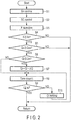
FIG. 2 is a flowchart showing control of one embodiment. -
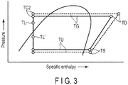
FIG. 3 is a Mollier diagram showing a change of a refrigerant temperature TL in one embodiment. - One embodiment will be described hereinafter with reference to the accompanying drawings.
- As shown in
FIG. 1 , a four-way valve 3 is connected to the discharge port of acompressor 1 via a high-pressure side pipe 2, and one end of anoutdoor heat exchanger 5 is connected to the four-way valve 3 via a gas side pipe 4. One end of a pressure reducing unit, for example, an electric expansion value (first electric expansion value) 7 is connected to the other end of theoutdoor heat exchanger 5 via aliquid side pipe 6, and a packedvalve 9 is connected to the other end of theelectric expansion value 7 via a liquid side pipe 8. Theelectric expansion value 7 is a pulse motor valve (PMV) whose opening degree Qo changes according to the number of input driving pulse signals. The opening degree Qo can be changed continuously from a minimum opening degree Qomin (fully closed) corresponding to 0 driving pulse signals pls to a maximum opening degree Qomax (fully open) corresponding to 3000 driving pulse signals pls. - One ends of a plurality of
indoor heat exchangers 42 are connected to the packedvalve 9 via a liquidside crossover pipe 31 and a plurality of electric expansion valves (second electric expansion valves) 41, and the other ends of theindoor heat exchangers 42 are connected to a packedvalve 10 via a gasside crossover pipe 32. Eachelectric expansion valve 41 is a pulse motor valve (PMV) whose opening degree Qi changes according to the number of input driving pulse signals. The opening degree Qi can be changed continuously from a minimum opening degree Qimin (fully closed) corresponding to 0 driving pulse signals pls to a maximum opening degree Qimax (fully open) corresponding to 1500 driving pulse signals pls. - The four-
way valve 3 is connected to the packedvalve 10 via agas side pipe 11, and the inflow port of anaccumulator 13 is connected to the four-way valve 3 via a low-pressure side pipe 12. Asuction cup 15 of thecompressor 1 is connected to the outflow port of the accumulator via a low-pressure side pipe 14. - According to these pipe connections, a heat pump type refrigeration cycle is formed.
- The
compressor 1 is a hermetic compressor in which a motor 1M operated by the output of aninverter 18 is accommodated in a hermetically-closed case, and sucks in a refrigerant flowing out of theaccumulator 13 and compresses and discharges the sucked refrigerant. Theinverter 18 converts the voltage of anAD power supply 19 into a DC voltage, and converts the DC voltage into a frequency F (referred to as an output frequency F) according to a command from anoutdoor controller 20 and an AC voltage having a level corresponding to the frequency F and outputs them. The speed of the motor 1M, that is, the capacity of thecompressor 1 changes according to the value of the output frequency F. - During a cooling operation, as indicated by solid arrows, the refrigerant discharged from the
compressor 1 flows into eachindoor heat exchanger 42 thorough the four-way valve 3, theoutdoor heat exchanger 5, theelectric expansion valve 7 and eachelectric expansion valve 41. The refrigerant flowing out of eachindoor heat exchanger 42 is sucked into thecompressor 1 through the four-way valve 3 and theaccumulator 13. Theoutdoor heat exchanger 5 functions as a condenser, and eachindoor heat exchanger 42 functions as an evaporator. - During a heating operation, the flow path of the four-
way valve 3 is switched, and as indicated by dashed arrows, the refrigerant discharged from thecompressor 1 flows into eachindoor heat exchanger 42 through the four-way valve 3. The refrigerant flowing out of eachindoor heat exchanger 42 is sucked into thecompressor 1 through theelectric expansion valve 7, theoutdoor heat exchanger 5, the four-way valve 3 and theaccumulator 13. Eachindoor heat exchanger 42 functions as a condenser, and theoutdoor heat exchanger 5 functions as an evaporator. - An
outdoor fan 16 which sucks in outdoor air and supplies it to theoutdoor heat exchanger 5 is disposed close to theexternal heat exchanger 5. An outdoorair temperature sensor 17 which detects an outdoor air temperature To is disposed in the flow path of the outdoor air sucked in by theoutdoor fan 16. Atemperature sensor 21 which detects a high-pressure side refrigerant temperature TD and apressure sensor 22 which detects a high-pressure side refrigerant pressure PD are attached to the high-pressure side pipe 2 located between the discharge port of thecompressor 1 and the four-way valve 3. Atemperature sensor 23 which detects a refrigerant temperature TL is attached to the liquid side pipe 8 located between theelectric expansion valve 7 and the packedvalve 9. Atemperature sensor 24 which detects a low-pressure side refrigerant temperature TS and apressure sensor 25 which detects a low-pressure side refrigerant pressure PS are attached to the low-pressure side pipe 12 located between the four-way valve 3 and theaccumulator 13. - An
indoor fan 43 which sucks in indoor air and supplies it to eachindoor heat exchanger 42 is disposed close to eachindoor heat exchanger 42. An indoorair temperature sensor 44 which detects an indoor temperature Ta is disposed in the flow path of the indoor air sucked in by theindoor fan 43. - A
temperature sensor 47 which detects a temperature TC2 of the refrigerant flowing out of eachindoor heat exchanger 42 during the heating operation is attached to the other end of eachindoor heat exchanger 42. Atemperature sensor 48 which detects a temperature TC1 of the refrigerant flowing into eachindoor heat exchanger 42 during the heating operation is attached to one end of eachindoor heat exchanger 42. The detection signals of thesetemperature sensors indoor controller 45. A remote control type operator (so-called remote control) 46 for allowing the user to set various operation conditions such as a cooling operation, a dehumidifying operation, a heating operation, an air blowing operation, a target indoor temperature Tas, an operation start and an operation stop is connected to eachindoor controller 45. - The
compressor 1, the four-way valve 3, theoutdoor heat exchanger 5, theelectric expansion valve 7, the packedvalves accumulator 13, theoutdoor fan 16, theinverter 18, theoutdoor controller 20, the respective pipes and the respective sensors described above are accommodated in an outdoor unit A. Theindoor heat exchanger 42, theoutdoor fan 43, theindoor controller 45, theoperator 46, the respective pipes and the respective sensors described above are accommodated in each of N indoor units B1, B2, ... , Bn. These outdoor unit A and indoor units B1, B2, ... , Bn constitute a multi-type air conditioning apparatus. In addition, theoutdoor controller 20 and eachindoor controller 45 are interconnected by asignal line 50 for data transmission. - The
outdoor controller 20 controls the operations of the outdoor unit A and each of the indoor units B1 to Bn by coordinating with each of theindoor controllers 45, and includes afirst control section 20a, asecond control section 20b, adetection section 20c and athird control section 20d as main functions. - The
first control section 20a executes superheat degree control in which the opening degree Qo of theelectric expansion valve 7 is controlled such that a superheat degree SH of the refrigerant in the outdoor heat exchanger (evaporator 5) is set to a target value SHs during the heating operation. The superheat degree SH of the refrigerant corresponds to the difference between the detection temperature TL of thetemperature sensor 23 and the detection temperature TS of thetemperature sensor 24. - During the heating operation, the
second control section 20b executes subcooling degree control in which the opening degree Qi of theelectric expansion valve 41 of each of one or more indoor units in an operating state is operated such that a subcooling degree SC of the refrigerant in the indoor heat exchanger (condenser) 42 of each of the indoor units is set to a target value SCs, and fully closes theelectric expansion valve 41 of each of one or more indoor units in an operation stopped state. The difference between a condensation temperature TG of the refrigerant in eachindoor heat exchanger 42 and the detection temperature TC2 of eachtemperature sensor 47 can be obtained as the subcooling degree SC of the refrigerant in eachindoor heat exchanger 42. The condensation temperature TG can be obtained by conversion from the refrigerant pressure PD detected by thepressure sensor 22 of the high-pressure side pipe 2. In addition, when the difference between the target indoor temperature Tas of theoperator 46 and the detection temperature Ta of theindoor temperature sensor 44 in the indoor unit in the operating state increases and the heating load increases in association with the execution of the subcooling degree control, thesecond control section 20b reduces the target value SCs with respect to the subcooling degree SC and changes the opening degree Qo of theelectric expansion value 7 in the increasing direction, and increases the refrigerant flow amount into theindoor heat exchanger 42 and increases the heating capacity. Furthermore, when the difference between the target indoor temperature Tas of theoperator 46 and the detection temperature Ta of theindoor temperature sensor 44 in the indoor unit in the operating state decreases and the heating load decreases in association with the execution of the subcooling degree control, thesecond control section 20b increases the target value SCs with respect to the subcooling degree SC and changes the opening degree Qo of theelectric expansion valve 7 in the decreasing direction, and reduces the refrigerant flow amount into theindoor heat exchanger 42 and reduces the heating capacity. - The
detection section 20c detects the refrigerant circulation amount in the heat pump type refrigeration cycle during the heating operation, more specifically, thedetection section 20c detects a shortage rate X (%) of the refrigerant circulation amount. - When the refrigerant circulation amount detected in the
detection section 20c is insufficient, more specifically, when the shortage rate X detected in thedetection section 20c is greater than or equal to a threshold value Xs (for example, 30%) and cannot be ignored, thethird control section 20d gradually increases the opening degree Qi of theelectric expansion valve 41 in each of the one or more indoor units in the operation stopped state from the fully closed state. More specifically, when the shortage rate X detected in thedetection section 20c is greater than or equal to the threshold value Xs and the opening degree Qo of theelectric expansion valve 7 operated by the superheat degree control of thefirst control section 20a is greater than or equal to a set value Qos (that is, when the increase of the superheat degree SH associated with the shortage of the refrigerant circulation amount cannot be suppressed by the superheat degree control), thethird control section 20d gradually increases the opening degree Qi of theelectric expansion valve 41 in each of the one or more indoor units in the operation stopped state by a certain opening degree ΔQ from the fully closed state to an upper limit of a predetermined opening degree Qis (for example, 10% of the maximum opening degree Qimax). The set value Qos corresponds to, for example, an opening degree of 2/3 of the maximum opening degree Qomax. The predetermined opening Qis set as the upper limit prevents unnecessary refrigerant inflow due to excessive opening of theelectric expansion valve 41. - The shortage rate X of the refrigerant circulation amount can be detected using one or more elements of the condensation temperature TG of the refrigerant in the condenser, an evaporation temperature TU of the refrigerant in the evaporator (indoor heat exchanger 42), the temperature TC2 (detection temperature of the temperature sensor 47) of the refrigerant flowing out of the evaporator, and the temperature TL (detection temperature of the temperature sensor 23) flowing into the condenser. The evaporator temperature TU can be obtained by conversion from the detection pressure PS of the
pressure sensor 25 in the low-pressure side pipe 12. - For example, when the refrigerant in the heat pump type refrigeration cycle circulates properly without accumulating in any of the indoor units B1 to Bn and there is no shortage of the refrigeration circulation amount, the liquid
side crossover pipe 31 and theliquid side pipes 8 and 9 are filled with the liquid refrigerant, and the liquid refrigerant flows into the outdoor heat exchanger (evaporator) 5. When the refrigerant accumulates in any of the indoor units B1 to Bn and the refrigerant circulation amount in the heat pump type refrigeration cycle becomes insufficient, the liquid refrigerant and the gas refrigerant coexist and flow through the liquidside crossover pipe 31 and theliquid side pipes 8 and 7, and the so-called gas-liquid two-phase refrigerant flows into theoutdoor heat exchanger 5. - When the gas-liquid two-phase refrigerant flows into the
outdoor heat exchanger 5, the superheat degree SH of the refrigerant in theoutdoor heat exchanger 5 increases, and in order to suppress the increase of the superheat degree SH, the superheat degree control is executed and the opening degree Qo of theelectric expansion valve 7 is changed in the increasing direction. However, when the increase of the opening degree Qo of theelectric expansion valve 7 continues and the opening degree Qo reaches the maximum opening degree Qomax of theelectric expansion valve 7, the increase of the superheat degree SH cannot be suppressed, and the temperature TS of the refrigerant sucked into thecompressor 1 increases. When the refrigerant temperature TS increases, the temperature TD (and the pressure PD) of the refrigerant discharged from thecompressor 1 increases, and due to high-pressure protection control of theindoor controller 20 against the increase of the refrigerant temperature TD, the output frequency F of theinverter 18 decreases. When the output frequency F decreases, the capacity of thecompressor 1 decreases, and the heating capacity in the indoor unit in the operating state decreases accordingly. - The state of the heat pump type refrigeration cycle when the liquid refrigerant flows into the
outdoor heat exchanger 5 is indicated by a solid line in the Mollier diagram ofFIG. 3 , and the state of the heat pump type refrigeration cycle when the gas-liquid two-phase refrigerant flows into theoutdoor heat exchanger 5 is indicated by a dashed line in the same Mollier diagram. The refrigerant temperature TL is close to the condensation temperature TG when the liquid refrigerant flows in. On the other hand, the refrigerant temperature TL is a value TL' far from the condensation temperature TG and close to the evaporation temperature TU when the gas-liquid two-phase refrigerant flows in. - Therefore, the
detection section 20c detects where the actual refrigerant temperature TL detected by thetemperature sensor 23 is located between the refrigerant temperature TL and the refrigerant temperature TL' in the Mollier diagram as the shortage rate X (%) of the refrigerant circulation amount. That is, the shortage rate is 0% when the actual refrigerant temperature TL is located at the same position as the refrigerant temperature TL in the Mollier diagram, the shortage rate X is 50% when the actual refrigerant temperature TL is located at the middle position between the refrigerant temperature TL and the refrigerant temperature TL' in the Mollier diagram, and the shortage rate X is 100% when the actual refrigerant temperature TL is located at the same position as the refrigerant temperature TL' in the Mollier diagram. - Next, control executed by the
outdoor controller 20 will be described with reference to a flowchart ofFIG. 2 . Steps S1, S2, and the like in the flowchart are referred to simply as S1, S2, and the like. - During the heating operation, the
outdoor controller 20 controls the opening degree of theelectric expansion valve 7 such that the superheat degree SH of the refrigerant in the outdoor heat exchanger (evaporator) 5 is set to the target value SHs (S1). Simultaneously, theoutdoor controller 20 controls the opening degree of theelectric expansion valve 41 of each of one or more indoor units in the operating state, for example, the indoor units B1 and B2 such that the subcooling degree SC of the refrigerant in theindoor heat exchanger 42 in each of the indoor units is set to the target value Cs, and fully closes theelectric expansion valve 41 of each of one or more indoor units in the operation stopped state, for example, the indoor units B3 to Bn (S2). - Then, the
outdoor controller 20 detects the shortage rate X of the refrigerant circulation amount in the heat pump type refrigeration cycle (S3), and determines whether the detected shortage rate X is greater than or equal to the threshold value Xs or not (S4). When the detected shortage rate X is not greater than or equal to the threshold value Xs (NO in S4), theoutdoor controller 20 repeats the processes from S1. - When the detected shortage rate X is greater than or equal to the threshold value Xs (YES in S4), the
outdoor controller 20 determines whether the opening degree Qo of theelectric expansion valve 7 adjusted by the superheat degree control is greater than or equal to the set value Qos or not (S5). When the opening degree Qo is not greater than or equal to the set value Qos (NO in S5), theoutdoor controller 20 repeats the processes from S1. - When the opening degree Qo is greater than or equal to the set value Qos (YES in S5), on the condition that the opening degree Qi of the
electric expansion valve 41 of each of the indoor units B3 to Bn in the operation stopped state is less than the predetermined opening degree Qis (YES in S6), theoutdoor controller 20 increases the opening degree Qi of theelectric expansion valve 41 of each of the indoor units B3 to Bn by the predetermined opening degree ΔQ (S7). When each fully closedelectric expansion valve 41 is opened, the stagnant refrigerant accumulating and liquefied in theindoor heat exchanger 42 of each of the indoor units B3 to Bn flows out to the liquidside crossover pipe 31 and the liquid side pipe 8. - In association with the increase of the opening degree, the
outdoor controller 20 starts a time count t (S8), and determines whether the time count t has reached a certain time ts (for example, 300 seconds) or not (S9). When the time count t is less than the certain time ts (NO in S9), theoutdoor controller 20 holds the increased opening degree Qi of the electric expansion valve 41 (S10) and continues the time count t (S8). Then, when the time count t reaches the certain time ts (YES in S9), theoutdoor controller 20 detects the shortage rate X of the refrigerant circulation amount again (S3) through the processes of S1 and S2. - When the detected shortage rate X is greater than or equal to the threshold value Xs regardless of the increase of the opening degree (YES in S4) and the opening degree Qo of the
electric expansion valve 7 is greater than or equal to the set value Qos (YES in S5), on the condition that the opening degree Qi of theelectric expansion valve 41 of each of the indoor units B3 to Bn in the operation stopped state is less than the predetermined opening degree Qis (YES in S6), theoutdoor controller 20 increases the opening degree Qi of theelectric expansion valve 41 of each of the indoor units B1 to Bn by the predetermined opening degree ΔQ again (S7). When the opening degree Qi of each fully closedelectric expansion valve 41 is further increased, the stagnant refrigerant accumulating and liquefied in theindoor heat exchanger 42 of each of the indoor units B3 to Bn further flows out to the liquidside crossover pipe 31 and the liquid side pipe 8. - In association with the increase of the opening degree, the
outdoor controller 20 starts the time count t over again (S8), and determines whether the time count t has reached the certain time ts or not (S9). When the time count t is less than the certain time ts (NO in S9), theoutdoor controller 20 holds the increased opening degree Qi of the electric expansion valve 41 (S10), and continues the time count t (S8). When the time count t reaches the certain time ts (YES in S9), theoutdoor controller 20 repeats the detection of the shortage rate X of the refrigerant circulation amount through the processes of S1 and S2 (S3). - When the opening degree Qi of the
electric expansion valve 41 in each of the indoor units B3 to Bn in the operation stopped state reaches the set value Qis in S6 (YES in S6), theoutdoor controller 20 starts the time count t over again without executing the process of increasing the opening degree of S7 (S8). - As described above, when the refrigerant circulation amount is insufficient, the
electric expansion valve 41 of each of the indoor units B3 to Bn in the operation stopped state is opened from the fully closed state and the opening degree Qi is gradually increased at intervals of the certain time ts, and this gradually promotes the outflow of the stagnant refrigerant accumulating in theindoor heat exchanger 42 in each of the outdoor units B3 to Bn. According to the outflow, the gas-liquid two-phase state of the refrigerant in the liquidside crossover pipe 31 and theliquid side pipes 8 and 7 is gradually dissolved. - When the gas-liquid two-phase refrigerant does not flow into the
outdoor heat exchanger 5, an unnecessary increase of the superheat degree SH of the refrigerant in theoutdoor heat exchanger 5 can be prevented, and an unnecessary increase of the opening degree Qo of theelectric expansion valve 7 due to the superheat degree control can be prevented. In accordance with this, an unnecessary increase of the temperature TS of the refrigerant sucked into thecompressor 1 can be avoided, and an unnecessary increase of the temperature TD (and the pressure PD) of the refrigerant discharged from thecompressor 1 can be avoided, and consequently, an unnecessary decrease of the output frequency F of theinverter 18 due to the high-pressure protection control can be avoided. As a result, an unnecessary decrease of the heating capacity in the indoor unit in the operating state can be prevented. - When the opening degree Qi of the
electric expansion valve 41 is significantly increased at once, a large amount of refrigerant flows into each of the indoor units B3 to Bn in the operation stopped state at once. However, since the opening degree Qi of theelectric expansion valve 41 is gradually increased at intervals of the certain time ts, a large amount of refrigerant does not flow into each of the indoor units B3 to Bn in the operation stopped state at once, and a stable and efficient energy-saving operation of the pump-type refrigeration cycle can be achieved. - In the above-described embodiment, the ratio of the value of the refrigerant temperature TL to the value of the condensation temperature TG is detected as the shortage rate (%) of the refrigerant circulation amount. However, it is not limited to this, and basically, one or more elements of the condensation temperature TG, the evaporation temperature TU, the refrigerant temperature TC2 and the refrigerant temperature TL may be used for detection.
- Since the shortage rate X (%) can also be viewed as a sufficiency rate Y (%) of an opposite concept, the sufficiency rate Y (%) of a concept opposite to the shortage rate X (%) may be detected. The sufficiency rate Y (%) approaches 0% as the shortage of the refrigerant circulation amount increases, and approaches 100% as the shortage of the refrigerant circulation amount decreases. That is, the sufficiency rate Y = 100% when the shortage rate X = 0%, the sufficiency rate Y = 50% when the shortage rate X = 50%, and the sufficiency rate Y = 0% when the shortage rate X is 100%.
- In the above-described embodiment, when the shortage rate X of the refrigerant circulation amount is greater than or equal to the threshold value Xs and the opening degree Qo of the
electric expansion valve 7 is greater than or equal to the set value Qos, the control for gradually increasing the opening degree Qi of theelectric expansion valve 41 is started. However, the condition that the opening degree Qo of theelectric expansion valve 7 is greater than or equal to the set value Qos may be omitted, and the control for gradually increasing theelectric expansion valve 41 may be immediately started when the shortage rate X of the refrigerant circulation amount is greater than or equal to the threshold value Xs. - While certain embodiment and modification example have been described, they have been presented by way of example only, and are not intended to limit the scope of the invention. Indeed, the novel embodiment and modification example described herein may be embodied in a variety of other forms; furthermore, various omissions, substitutions and changes in the form of the embodiment described herein may be made without departing from the spirit of the invention. The accompanying claims and their equivalents are intended to cover such forms or modifications as would fall within the scope and spirit of the invention.
- A···Outdoor unit, B1 to Bn···Indoor units, 1···Compressor, 3···Four-way valve, 5···Outdoor heat exchanger, 7···Electric expansion valve, 16···Outdoor fan, 18 Invertor, 20···Outdoor controller, 41···Electric expansion valve, 42···Indoor heat exchanger, 43···Indoor fan, 45···Indoor controller, and 46···Operator.
Claims (6)
- An air conditioning apparatus comprising:an outdoor unit including a compressor, an outdoor heat exchanger and a first electric expansion valve;a plurality of indoor units each including a second electric expansion valve and an indoor heat exchanger;a refrigeration cycle in which a refrigerant discharged from the compressor flows into each of the indoor heat exchangers, the refrigerant flowing out of each of the indoor heat exchangers flows into the outdoor heat exchanger through each of the second electric expansion valves and the first electric expansion value, and the refrigerant flowing out of the outdoor heat exchanger returns to the compressor, during a heating operation; anda controller which controls operations of the outdoor unit and each of the indoor units, characterized in thatthe controller opens the second electric expansion valve in each of one or more indoor units in an operating state of the indoor units, and fully closes the second electric expansion valve in each of one or more indoor units in an operation stopped state of the indoor units, andwhen a refrigerant circulation amount in the refrigeration cycle is insufficient, the controller gradually increases an opening degree of the second electric expansion valve in each of the one or more indoor units in the operation stopped state.
- The air conditioning apparatus of claim 1, characterized in thatthe controller detects a shortage rate of the refrigerant circulation amount in the refrigeration cycle, andwhen the detected shortage rate is greater than or equal to a threshold value, the controller gradually increases the opening degree of the second electric expansion valve in each of the one or more indoor units in the operation stopped state.
- The air conditioning apparatus of claim 1, characterized in thatthe controller detects a shortage rate of the refrigerant circulation amount in the refrigeration cycle, andwhen the detected shortage rate is greater than or equal to a threshold value, the controller gradually increases the opening degree of the second electric expansion valve in the one or more indoor units in the operation stopped state to an upper limit of a predetermined opening degree.
- The air conditioning apparatus of claim 1, characterized in thatthe controller controls an opening degree of the first electric expansion valve such that a superheat degree of the refrigerant in the outdoor heat exchanger is set to a target value, andthe controller controls the opening degree of the second electric expansion valve in the one or more indoor units in the operating state of the indoor units such that a subcooling degree of the refrigerant in the indoor heat exchanger in each of the indoor units is set to a target value.
- The air conditioning apparatus of claim 4, characterized in thatthe controller detects a shortage rate of the refrigerant circulation amount in the refrigeration cycle, andwhen the detected shortage rate is greater than or equal to a threshold value and the opening degree of the first electric expansion valve is greater than or equal to a set value, the controller gradually increases the opening degree of the second electric expansion valve in each of the one or more indoor units in the operation stopped state.
- The air conditioning apparatus of claim 4, characterized in thatthe controller detects a shortage rate of the refrigeration circulation amount in the refrigeration cycle, andwhen the detected shortage rate is greater than or equal to a threshold value and the opening degree of the first electric expansion valve is greater than or equal to a set value, the controller gradually increases the opening degree of the second electric expansion valve in each of the one or more indoor units in the operation stopped state to an upper limit of a predetermined opening degree.
Applications Claiming Priority (1)
| Application Number | Priority Date | Filing Date | Title |
|---|---|---|---|
| PCT/JP2018/035477 WO2020065730A1 (en) | 2018-09-25 | 2018-09-25 | Air conditioning device |
Publications (3)
| Publication Number | Publication Date |
|---|---|
| EP3859231A1 true EP3859231A1 (en) | 2021-08-04 |
| EP3859231A4 EP3859231A4 (en) | 2022-05-18 |
| EP3859231B1 EP3859231B1 (en) | 2024-10-30 |
Family
ID=69952974
Family Applications (1)
| Application Number | Title | Priority Date | Filing Date |
|---|---|---|---|
| EP18935928.4A Active EP3859231B1 (en) | 2018-09-25 | 2018-09-25 | Air conditioning device |
Country Status (4)
| Country | Link |
|---|---|
| EP (1) | EP3859231B1 (en) |
| JP (1) | JP7047120B2 (en) |
| CN (1) | CN112771320B (en) |
| WO (1) | WO2020065730A1 (en) |
Family Cites Families (14)
| Publication number | Priority date | Publication date | Assignee | Title |
|---|---|---|---|---|
| JP3331620B2 (en) * | 1992-05-11 | 2002-10-07 | ダイキン工業株式会社 | Operation control device for air conditioner |
| JPH0835710A (en) * | 1994-07-22 | 1996-02-06 | Mitsubishi Heavy Ind Ltd | Control device for multi-type air conditioner |
| JP4100853B2 (en) * | 2000-02-14 | 2008-06-11 | 三洋電機株式会社 | Air conditioner |
| JP4110276B2 (en) * | 2003-10-03 | 2008-07-02 | 株式会社日立製作所 | Refrigerant filling apparatus and refrigerant filling method |
| KR100546616B1 (en) * | 2004-01-19 | 2006-01-26 | 엘지전자 주식회사 | Control method of multi air conditioner |
| KR100550566B1 (en) * | 2004-02-25 | 2006-02-10 | 엘지전자 주식회사 | Control method of multi type heat pump |
| CN100580347C (en) * | 2005-04-07 | 2010-01-13 | 大金工业株式会社 | Refrigerant amount determination system for air conditioner |
| JP4730738B2 (en) * | 2005-12-26 | 2011-07-20 | 日立アプライアンス株式会社 | Air conditioner |
| JP5138292B2 (en) * | 2007-07-04 | 2013-02-06 | 三菱重工業株式会社 | Air conditioner |
| JP4383472B2 (en) * | 2007-08-27 | 2009-12-16 | 三洋電機株式会社 | Air conditioner |
| JP2009250554A (en) * | 2008-04-09 | 2009-10-29 | Daikin Ind Ltd | Refrigerating device |
| CN103245148B (en) * | 2013-05-24 | 2015-08-05 | 四川长虹空调有限公司 | For the oil of air-conditioning and coolant control device and method, air-conditioning system and air-conditioning |
| WO2017026025A1 (en) * | 2015-08-10 | 2017-02-16 | 三菱電機株式会社 | Multiple-type air conditioner |
| JP6652424B2 (en) * | 2016-03-28 | 2020-02-26 | 東芝キヤリア株式会社 | Air conditioner |
-
2018
- 2018-09-25 CN CN201880098056.1A patent/CN112771320B/en active Active
- 2018-09-25 WO PCT/JP2018/035477 patent/WO2020065730A1/en not_active Ceased
- 2018-09-25 JP JP2020547640A patent/JP7047120B2/en active Active
- 2018-09-25 EP EP18935928.4A patent/EP3859231B1/en active Active
Also Published As
| Publication number | Publication date |
|---|---|
| WO2020065730A1 (en) | 2020-04-02 |
| JP7047120B2 (en) | 2022-04-04 |
| EP3859231A4 (en) | 2022-05-18 |
| CN112771320A (en) | 2021-05-07 |
| CN112771320B (en) | 2022-08-02 |
| EP3859231B1 (en) | 2024-10-30 |
| JPWO2020065730A1 (en) | 2021-08-30 |
Similar Documents
| Publication | Publication Date | Title |
|---|---|---|
| US10168066B2 (en) | Air conditioner with outdoor fan control in accordance with suction pressure and suction superheating degree of a compressor | |
| US9151522B2 (en) | Air conditioner and control method thereof | |
| US11125473B2 (en) | Air conditioner | |
| JP6792057B2 (en) | Refrigeration cycle equipment | |
| EP2584291A2 (en) | Air conditioner and operation method of the same | |
| JP7262595B2 (en) | air conditioner | |
| CN112119273B (en) | Refrigeration cycle device | |
| JPH0828985A (en) | Air conditioner | |
| US20140311172A1 (en) | Outdoor unit and air-conditioning apparatus | |
| EP3051219B1 (en) | Outdoor unit of air conditioner and air conditioner | |
| KR102688990B1 (en) | An air conditioning apparatus and control method thereof | |
| EP1881277A1 (en) | Air conditioner | |
| EP1972861B1 (en) | Simultaneous Heating and Cooling Type Multi-Air Conditioner and Method for Controlling the Same | |
| JPH11142001A (en) | Air conditioner | |
| US20090077985A1 (en) | Refrigerating Apparatus | |
| EP3859231B1 (en) | Air conditioning device | |
| EP4151926A1 (en) | Refrigeration cycle device | |
| JP7308978B2 (en) | air conditioner | |
| US20230140815A1 (en) | Refrigeration system and heat source unit | |
| CN114341569A (en) | Heat source unit and refrigerating device | |
| US20250180245A1 (en) | Air-conditioning apparatus | |
| CN112771321A (en) | Air conditioner | |
| CN116075673A (en) | air conditioner | |
| US20250369672A1 (en) | Air conditioning device | |
| US20250207830A1 (en) | Heat source unit and refrigeration apparatus |
Legal Events
| Date | Code | Title | Description |
|---|---|---|---|
| STAA | Information on the status of an ep patent application or granted ep patent |
Free format text: STATUS: THE INTERNATIONAL PUBLICATION HAS BEEN MADE |
|
| PUAI | Public reference made under article 153(3) epc to a published international application that has entered the european phase |
Free format text: ORIGINAL CODE: 0009012 |
|
| STAA | Information on the status of an ep patent application or granted ep patent |
Free format text: STATUS: REQUEST FOR EXAMINATION WAS MADE |
|
| 17P | Request for examination filed |
Effective date: 20210323 |
|
| AK | Designated contracting states |
Kind code of ref document: A1 Designated state(s): AL AT BE BG CH CY CZ DE DK EE ES FI FR GB GR HR HU IE IS IT LI LT LU LV MC MK MT NL NO PL PT RO RS SE SI SK SM TR |
|
| DAV | Request for validation of the european patent (deleted) | ||
| DAX | Request for extension of the european patent (deleted) | ||
| A4 | Supplementary search report drawn up and despatched |
Effective date: 20220420 |
|
| RIC1 | Information provided on ipc code assigned before grant |
Ipc: F24F 140/00 20180101ALI20220412BHEP Ipc: F25B 13/00 20060101ALI20220412BHEP Ipc: F24F 11/86 20180101ALI20220412BHEP Ipc: F25B 1/00 20060101AFI20220412BHEP |
|
| GRAP | Despatch of communication of intention to grant a patent |
Free format text: ORIGINAL CODE: EPIDOSNIGR1 |
|
| STAA | Information on the status of an ep patent application or granted ep patent |
Free format text: STATUS: GRANT OF PATENT IS INTENDED |
|
| INTG | Intention to grant announced |
Effective date: 20240521 |
|
| GRAS | Grant fee paid |
Free format text: ORIGINAL CODE: EPIDOSNIGR3 |
|
| GRAA | (expected) grant |
Free format text: ORIGINAL CODE: 0009210 |
|
| STAA | Information on the status of an ep patent application or granted ep patent |
Free format text: STATUS: THE PATENT HAS BEEN GRANTED |
|
| RAP3 | Party data changed (applicant data changed or rights of an application transferred) |
Owner name: CARRIER JAPAN CORPORATION |
|
| AK | Designated contracting states |
Kind code of ref document: B1 Designated state(s): AL AT BE BG CH CY CZ DE DK EE ES FI FR GB GR HR HU IE IS IT LI LT LU LV MC MK MT NL NO PL PT RO RS SE SI SK SM TR |
|
| REG | Reference to a national code |
Ref country code: GB Ref legal event code: FG4D |
|
| REG | Reference to a national code |
Ref country code: CH Ref legal event code: EP |
|
| REG | Reference to a national code |
Ref country code: IE Ref legal event code: FG4D |
|
| REG | Reference to a national code |
Ref country code: DE Ref legal event code: R096 Ref document number: 602018076146 Country of ref document: DE |
|
| REG | Reference to a national code |
Ref country code: LT Ref legal event code: MG9D |
|
| REG | Reference to a national code |
Ref country code: NL Ref legal event code: MP Effective date: 20241030 |
|
| PG25 | Lapsed in a contracting state [announced via postgrant information from national office to epo] |
Ref country code: IS Free format text: LAPSE BECAUSE OF FAILURE TO SUBMIT A TRANSLATION OF THE DESCRIPTION OR TO PAY THE FEE WITHIN THE PRESCRIBED TIME-LIMIT Effective date: 20250228 Ref country code: HR Free format text: LAPSE BECAUSE OF FAILURE TO SUBMIT A TRANSLATION OF THE DESCRIPTION OR TO PAY THE FEE WITHIN THE PRESCRIBED TIME-LIMIT Effective date: 20241030 Ref country code: PT Free format text: LAPSE BECAUSE OF FAILURE TO SUBMIT A TRANSLATION OF THE DESCRIPTION OR TO PAY THE FEE WITHIN THE PRESCRIBED TIME-LIMIT Effective date: 20250228 |
|
| PG25 | Lapsed in a contracting state [announced via postgrant information from national office to epo] |
Ref country code: FI Free format text: LAPSE BECAUSE OF FAILURE TO SUBMIT A TRANSLATION OF THE DESCRIPTION OR TO PAY THE FEE WITHIN THE PRESCRIBED TIME-LIMIT Effective date: 20241030 Ref country code: NL Free format text: LAPSE BECAUSE OF FAILURE TO SUBMIT A TRANSLATION OF THE DESCRIPTION OR TO PAY THE FEE WITHIN THE PRESCRIBED TIME-LIMIT Effective date: 20241030 |
|
| REG | Reference to a national code |
Ref country code: AT Ref legal event code: MK05 Ref document number: 1737214 Country of ref document: AT Kind code of ref document: T Effective date: 20241030 |
|
| PG25 | Lapsed in a contracting state [announced via postgrant information from national office to epo] |
Ref country code: BG Free format text: LAPSE BECAUSE OF FAILURE TO SUBMIT A TRANSLATION OF THE DESCRIPTION OR TO PAY THE FEE WITHIN THE PRESCRIBED TIME-LIMIT Effective date: 20241030 |
|
| PG25 | Lapsed in a contracting state [announced via postgrant information from national office to epo] |
Ref country code: ES Free format text: LAPSE BECAUSE OF FAILURE TO SUBMIT A TRANSLATION OF THE DESCRIPTION OR TO PAY THE FEE WITHIN THE PRESCRIBED TIME-LIMIT Effective date: 20241030 |
|
| PG25 | Lapsed in a contracting state [announced via postgrant information from national office to epo] |
Ref country code: NO Free format text: LAPSE BECAUSE OF FAILURE TO SUBMIT A TRANSLATION OF THE DESCRIPTION OR TO PAY THE FEE WITHIN THE PRESCRIBED TIME-LIMIT Effective date: 20250130 |
|
| PG25 | Lapsed in a contracting state [announced via postgrant information from national office to epo] |
Ref country code: AT Free format text: LAPSE BECAUSE OF FAILURE TO SUBMIT A TRANSLATION OF THE DESCRIPTION OR TO PAY THE FEE WITHIN THE PRESCRIBED TIME-LIMIT Effective date: 20241030 Ref country code: GR Free format text: LAPSE BECAUSE OF FAILURE TO SUBMIT A TRANSLATION OF THE DESCRIPTION OR TO PAY THE FEE WITHIN THE PRESCRIBED TIME-LIMIT Effective date: 20250131 Ref country code: LV Free format text: LAPSE BECAUSE OF FAILURE TO SUBMIT A TRANSLATION OF THE DESCRIPTION OR TO PAY THE FEE WITHIN THE PRESCRIBED TIME-LIMIT Effective date: 20241030 |
|
| PG25 | Lapsed in a contracting state [announced via postgrant information from national office to epo] |
Ref country code: PL Free format text: LAPSE BECAUSE OF FAILURE TO SUBMIT A TRANSLATION OF THE DESCRIPTION OR TO PAY THE FEE WITHIN THE PRESCRIBED TIME-LIMIT Effective date: 20241030 |
|
| PG25 | Lapsed in a contracting state [announced via postgrant information from national office to epo] |
Ref country code: RS Free format text: LAPSE BECAUSE OF FAILURE TO SUBMIT A TRANSLATION OF THE DESCRIPTION OR TO PAY THE FEE WITHIN THE PRESCRIBED TIME-LIMIT Effective date: 20250130 |
|
| PG25 | Lapsed in a contracting state [announced via postgrant information from national office to epo] |
Ref country code: SM Free format text: LAPSE BECAUSE OF FAILURE TO SUBMIT A TRANSLATION OF THE DESCRIPTION OR TO PAY THE FEE WITHIN THE PRESCRIBED TIME-LIMIT Effective date: 20241030 |
|
| PG25 | Lapsed in a contracting state [announced via postgrant information from national office to epo] |
Ref country code: DK Free format text: LAPSE BECAUSE OF FAILURE TO SUBMIT A TRANSLATION OF THE DESCRIPTION OR TO PAY THE FEE WITHIN THE PRESCRIBED TIME-LIMIT Effective date: 20241030 |
|
| PG25 | Lapsed in a contracting state [announced via postgrant information from national office to epo] |
Ref country code: EE Free format text: LAPSE BECAUSE OF FAILURE TO SUBMIT A TRANSLATION OF THE DESCRIPTION OR TO PAY THE FEE WITHIN THE PRESCRIBED TIME-LIMIT Effective date: 20241030 |
|
| PG25 | Lapsed in a contracting state [announced via postgrant information from national office to epo] |
Ref country code: RO Free format text: LAPSE BECAUSE OF FAILURE TO SUBMIT A TRANSLATION OF THE DESCRIPTION OR TO PAY THE FEE WITHIN THE PRESCRIBED TIME-LIMIT Effective date: 20241030 |
|
| PG25 | Lapsed in a contracting state [announced via postgrant information from national office to epo] |
Ref country code: SK Free format text: LAPSE BECAUSE OF FAILURE TO SUBMIT A TRANSLATION OF THE DESCRIPTION OR TO PAY THE FEE WITHIN THE PRESCRIBED TIME-LIMIT Effective date: 20241030 |
|
| PG25 | Lapsed in a contracting state [announced via postgrant information from national office to epo] |
Ref country code: CZ Free format text: LAPSE BECAUSE OF FAILURE TO SUBMIT A TRANSLATION OF THE DESCRIPTION OR TO PAY THE FEE WITHIN THE PRESCRIBED TIME-LIMIT Effective date: 20241030 |
|
| PG25 | Lapsed in a contracting state [announced via postgrant information from national office to epo] |
Ref country code: IT Free format text: LAPSE BECAUSE OF FAILURE TO SUBMIT A TRANSLATION OF THE DESCRIPTION OR TO PAY THE FEE WITHIN THE PRESCRIBED TIME-LIMIT Effective date: 20241030 |
|
| REG | Reference to a national code |
Ref country code: DE Ref legal event code: R097 Ref document number: 602018076146 Country of ref document: DE |
|
| PLBE | No opposition filed within time limit |
Free format text: ORIGINAL CODE: 0009261 |
|
| STAA | Information on the status of an ep patent application or granted ep patent |
Free format text: STATUS: NO OPPOSITION FILED WITHIN TIME LIMIT |
|
| PG25 | Lapsed in a contracting state [announced via postgrant information from national office to epo] |
Ref country code: SE Free format text: LAPSE BECAUSE OF FAILURE TO SUBMIT A TRANSLATION OF THE DESCRIPTION OR TO PAY THE FEE WITHIN THE PRESCRIBED TIME-LIMIT Effective date: 20241030 |
|
| 26N | No opposition filed |
Effective date: 20250731 |
|
| PGFP | Annual fee paid to national office [announced via postgrant information from national office to epo] |
Ref country code: DE Payment date: 20250820 Year of fee payment: 8 |
|
| PGFP | Annual fee paid to national office [announced via postgrant information from national office to epo] |
Ref country code: GB Payment date: 20250822 Year of fee payment: 8 |
|
| PGFP | Annual fee paid to national office [announced via postgrant information from national office to epo] |
Ref country code: FR Payment date: 20250820 Year of fee payment: 8 |
|
| REG | Reference to a national code |
Ref country code: CH Ref legal event code: H13 Free format text: ST27 STATUS EVENT CODE: U-0-0-H10-H13 (AS PROVIDED BY THE NATIONAL OFFICE) Effective date: 20260504 |