EP3859155A1 - Gas compressor and method for controlling same - Google Patents
Gas compressor and method for controlling same Download PDFInfo
- Publication number
- EP3859155A1 EP3859155A1 EP19868013.4A EP19868013A EP3859155A1 EP 3859155 A1 EP3859155 A1 EP 3859155A1 EP 19868013 A EP19868013 A EP 19868013A EP 3859155 A1 EP3859155 A1 EP 3859155A1
- Authority
- EP
- European Patent Office
- Prior art keywords
- compressor
- bodies
- increase
- operated
- motor
- Prior art date
- Legal status (The legal status is an assumption and is not a legal conclusion. Google has not performed a legal analysis and makes no representation as to the accuracy of the status listed.)
- Granted
Links
Images


Classifications
-
- F—MECHANICAL ENGINEERING; LIGHTING; HEATING; WEAPONS; BLASTING
- F04—POSITIVE - DISPLACEMENT MACHINES FOR LIQUIDS; PUMPS FOR LIQUIDS OR ELASTIC FLUIDS
- F04B—POSITIVE-DISPLACEMENT MACHINES FOR LIQUIDS; PUMPS
- F04B41/00—Pumping installations or systems specially adapted for elastic fluids
- F04B41/06—Combinations of two or more pumps
-
- F—MECHANICAL ENGINEERING; LIGHTING; HEATING; WEAPONS; BLASTING
- F04—POSITIVE - DISPLACEMENT MACHINES FOR LIQUIDS; PUMPS FOR LIQUIDS OR ELASTIC FLUIDS
- F04B—POSITIVE-DISPLACEMENT MACHINES FOR LIQUIDS; PUMPS
- F04B35/00—Piston pumps specially adapted for elastic fluids and characterised by the driving means to their working members, or by combination with, or adaptation to, specific driving engines or motors, not otherwise provided for
- F04B35/04—Piston pumps specially adapted for elastic fluids and characterised by the driving means to their working members, or by combination with, or adaptation to, specific driving engines or motors, not otherwise provided for the means being electric
-
- F—MECHANICAL ENGINEERING; LIGHTING; HEATING; WEAPONS; BLASTING
- F04—POSITIVE - DISPLACEMENT MACHINES FOR LIQUIDS; PUMPS FOR LIQUIDS OR ELASTIC FLUIDS
- F04B—POSITIVE-DISPLACEMENT MACHINES FOR LIQUIDS; PUMPS
- F04B49/00—Control, e.g. of pump delivery, or pump pressure of, or safety measures for, machines, pumps, or pumping installations, not otherwise provided for, or of interest apart from, groups F04B1/00 - F04B47/00
- F04B49/06—Control using electricity
-
- F—MECHANICAL ENGINEERING; LIGHTING; HEATING; WEAPONS; BLASTING
- F04—POSITIVE - DISPLACEMENT MACHINES FOR LIQUIDS; PUMPS FOR LIQUIDS OR ELASTIC FLUIDS
- F04B—POSITIVE-DISPLACEMENT MACHINES FOR LIQUIDS; PUMPS
- F04B49/00—Control, e.g. of pump delivery, or pump pressure of, or safety measures for, machines, pumps, or pumping installations, not otherwise provided for, or of interest apart from, groups F04B1/00 - F04B47/00
- F04B49/06—Control using electricity
- F04B49/065—Control using electricity and making use of computers
-
- F—MECHANICAL ENGINEERING; LIGHTING; HEATING; WEAPONS; BLASTING
- F04—POSITIVE - DISPLACEMENT MACHINES FOR LIQUIDS; PUMPS FOR LIQUIDS OR ELASTIC FLUIDS
- F04B—POSITIVE-DISPLACEMENT MACHINES FOR LIQUIDS; PUMPS
- F04B49/00—Control, e.g. of pump delivery, or pump pressure of, or safety measures for, machines, pumps, or pumping installations, not otherwise provided for, or of interest apart from, groups F04B1/00 - F04B47/00
- F04B49/08—Regulating by delivery pressure
-
- F—MECHANICAL ENGINEERING; LIGHTING; HEATING; WEAPONS; BLASTING
- F04—POSITIVE - DISPLACEMENT MACHINES FOR LIQUIDS; PUMPS FOR LIQUIDS OR ELASTIC FLUIDS
- F04B—POSITIVE-DISPLACEMENT MACHINES FOR LIQUIDS; PUMPS
- F04B49/00—Control, e.g. of pump delivery, or pump pressure of, or safety measures for, machines, pumps, or pumping installations, not otherwise provided for, or of interest apart from, groups F04B1/00 - F04B47/00
- F04B49/20—Control, e.g. of pump delivery, or pump pressure of, or safety measures for, machines, pumps, or pumping installations, not otherwise provided for, or of interest apart from, groups F04B1/00 - F04B47/00 by changing the driving speed
-
- F—MECHANICAL ENGINEERING; LIGHTING; HEATING; WEAPONS; BLASTING
- F04—POSITIVE - DISPLACEMENT MACHINES FOR LIQUIDS; PUMPS FOR LIQUIDS OR ELASTIC FLUIDS
- F04C—ROTARY-PISTON, OR OSCILLATING-PISTON, POSITIVE-DISPLACEMENT MACHINES FOR LIQUIDS; ROTARY-PISTON, OR OSCILLATING-PISTON, POSITIVE-DISPLACEMENT PUMPS
- F04C14/00—Control of, monitoring of, or safety arrangements for, machines, pumps or pumping installations
- F04C14/02—Control of, monitoring of, or safety arrangements for, machines, pumps or pumping installations specially adapted for several machines or pumps connected in series or in parallel
-
- F—MECHANICAL ENGINEERING; LIGHTING; HEATING; WEAPONS; BLASTING
- F04—POSITIVE - DISPLACEMENT MACHINES FOR LIQUIDS; PUMPS FOR LIQUIDS OR ELASTIC FLUIDS
- F04C—ROTARY-PISTON, OR OSCILLATING-PISTON, POSITIVE-DISPLACEMENT MACHINES FOR LIQUIDS; ROTARY-PISTON, OR OSCILLATING-PISTON, POSITIVE-DISPLACEMENT PUMPS
- F04C23/00—Combinations of two or more pumps, each being of rotary-piston or oscillating-piston type, specially adapted for elastic fluids; Pumping installations specially adapted for elastic fluids; Multi-stage pumps specially adapted for elastic fluids
- F04C23/001—Combinations of two or more pumps, each being of rotary-piston or oscillating-piston type, specially adapted for elastic fluids; Pumping installations specially adapted for elastic fluids; Multi-stage pumps specially adapted for elastic fluids of similar working principle
-
- F—MECHANICAL ENGINEERING; LIGHTING; HEATING; WEAPONS; BLASTING
- F04—POSITIVE - DISPLACEMENT MACHINES FOR LIQUIDS; PUMPS FOR LIQUIDS OR ELASTIC FLUIDS
- F04C—ROTARY-PISTON, OR OSCILLATING-PISTON, POSITIVE-DISPLACEMENT MACHINES FOR LIQUIDS; ROTARY-PISTON, OR OSCILLATING-PISTON, POSITIVE-DISPLACEMENT PUMPS
- F04C28/00—Control of, monitoring of, or safety arrangements for, pumps or pumping installations specially adapted for elastic fluids
- F04C28/02—Control of, monitoring of, or safety arrangements for, pumps or pumping installations specially adapted for elastic fluids specially adapted for several pumps connected in series or in parallel
-
- F—MECHANICAL ENGINEERING; LIGHTING; HEATING; WEAPONS; BLASTING
- F04—POSITIVE - DISPLACEMENT MACHINES FOR LIQUIDS; PUMPS FOR LIQUIDS OR ELASTIC FLUIDS
- F04C—ROTARY-PISTON, OR OSCILLATING-PISTON, POSITIVE-DISPLACEMENT MACHINES FOR LIQUIDS; ROTARY-PISTON, OR OSCILLATING-PISTON, POSITIVE-DISPLACEMENT PUMPS
- F04C28/00—Control of, monitoring of, or safety arrangements for, pumps or pumping installations specially adapted for elastic fluids
- F04C28/08—Control of, monitoring of, or safety arrangements for, pumps or pumping installations specially adapted for elastic fluids characterised by varying the rotational speed
-
- F—MECHANICAL ENGINEERING; LIGHTING; HEATING; WEAPONS; BLASTING
- F04—POSITIVE - DISPLACEMENT MACHINES FOR LIQUIDS; PUMPS FOR LIQUIDS OR ELASTIC FLUIDS
- F04D—NON-POSITIVE-DISPLACEMENT PUMPS
- F04D17/00—Radial-flow pumps, e.g. centrifugal pumps; Helico-centrifugal pumps
- F04D17/08—Centrifugal pumps
- F04D17/10—Centrifugal pumps for compressing or evacuating
-
- F—MECHANICAL ENGINEERING; LIGHTING; HEATING; WEAPONS; BLASTING
- F04—POSITIVE - DISPLACEMENT MACHINES FOR LIQUIDS; PUMPS FOR LIQUIDS OR ELASTIC FLUIDS
- F04D—NON-POSITIVE-DISPLACEMENT PUMPS
- F04D25/00—Pumping installations or systems
- F04D25/16—Combinations of two or more pumps ; Producing two or more separate gas flows
-
- F—MECHANICAL ENGINEERING; LIGHTING; HEATING; WEAPONS; BLASTING
- F04—POSITIVE - DISPLACEMENT MACHINES FOR LIQUIDS; PUMPS FOR LIQUIDS OR ELASTIC FLUIDS
- F04D—NON-POSITIVE-DISPLACEMENT PUMPS
- F04D27/00—Control, e.g. regulation, of pumps, pumping installations or pumping systems specially adapted for elastic fluids
- F04D27/001—Testing thereof; Determination or simulation of flow characteristics; Stall or surge detection, e.g. condition monitoring
-
- F—MECHANICAL ENGINEERING; LIGHTING; HEATING; WEAPONS; BLASTING
- F04—POSITIVE - DISPLACEMENT MACHINES FOR LIQUIDS; PUMPS FOR LIQUIDS OR ELASTIC FLUIDS
- F04D—NON-POSITIVE-DISPLACEMENT PUMPS
- F04D27/00—Control, e.g. regulation, of pumps, pumping installations or pumping systems specially adapted for elastic fluids
- F04D27/02—Surge control
- F04D27/0261—Surge control by varying driving speed
-
- F—MECHANICAL ENGINEERING; LIGHTING; HEATING; WEAPONS; BLASTING
- F04—POSITIVE - DISPLACEMENT MACHINES FOR LIQUIDS; PUMPS FOR LIQUIDS OR ELASTIC FLUIDS
- F04D—NON-POSITIVE-DISPLACEMENT PUMPS
- F04D27/00—Control, e.g. regulation, of pumps, pumping installations or pumping systems specially adapted for elastic fluids
- F04D27/02—Surge control
- F04D27/0269—Surge control by changing flow path between different stages or between a plurality of compressors; load distribution between compressors
-
- F—MECHANICAL ENGINEERING; LIGHTING; HEATING; WEAPONS; BLASTING
- F25—REFRIGERATION OR COOLING; COMBINED HEATING AND REFRIGERATION SYSTEMS; HEAT PUMP SYSTEMS; MANUFACTURE OR STORAGE OF ICE; LIQUEFACTION SOLIDIFICATION OF GASES
- F25B—REFRIGERATION MACHINES, PLANTS OR SYSTEMS; COMBINED HEATING AND REFRIGERATION SYSTEMS; HEAT PUMP SYSTEMS
- F25B13/00—Compression machines, plants or systems, with reversible cycle
-
- F—MECHANICAL ENGINEERING; LIGHTING; HEATING; WEAPONS; BLASTING
- F25—REFRIGERATION OR COOLING; COMBINED HEATING AND REFRIGERATION SYSTEMS; HEAT PUMP SYSTEMS; MANUFACTURE OR STORAGE OF ICE; LIQUEFACTION SOLIDIFICATION OF GASES
- F25B—REFRIGERATION MACHINES, PLANTS OR SYSTEMS; COMBINED HEATING AND REFRIGERATION SYSTEMS; HEAT PUMP SYSTEMS
- F25B49/00—Arrangement or mounting of control or safety devices
- F25B49/02—Arrangement or mounting of control or safety devices for compression type machines, plants or systems
- F25B49/022—Compressor control arrangements
-
- F—MECHANICAL ENGINEERING; LIGHTING; HEATING; WEAPONS; BLASTING
- F25—REFRIGERATION OR COOLING; COMBINED HEATING AND REFRIGERATION SYSTEMS; HEAT PUMP SYSTEMS; MANUFACTURE OR STORAGE OF ICE; LIQUEFACTION SOLIDIFICATION OF GASES
- F25B—REFRIGERATION MACHINES, PLANTS OR SYSTEMS; COMBINED HEATING AND REFRIGERATION SYSTEMS; HEAT PUMP SYSTEMS
- F25B5/00—Compression machines, plants or systems, with several evaporator circuits, e.g. for varying refrigerating capacity
- F25B5/02—Compression machines, plants or systems, with several evaporator circuits, e.g. for varying refrigerating capacity arranged in parallel
-
- F—MECHANICAL ENGINEERING; LIGHTING; HEATING; WEAPONS; BLASTING
- F04—POSITIVE - DISPLACEMENT MACHINES FOR LIQUIDS; PUMPS FOR LIQUIDS OR ELASTIC FLUIDS
- F04B—POSITIVE-DISPLACEMENT MACHINES FOR LIQUIDS; PUMPS
- F04B2203/00—Motor parameters
- F04B2203/02—Motor parameters of rotating electric motors
- F04B2203/0204—Frequency of the electric current
-
- F—MECHANICAL ENGINEERING; LIGHTING; HEATING; WEAPONS; BLASTING
- F04—POSITIVE - DISPLACEMENT MACHINES FOR LIQUIDS; PUMPS FOR LIQUIDS OR ELASTIC FLUIDS
- F04B—POSITIVE-DISPLACEMENT MACHINES FOR LIQUIDS; PUMPS
- F04B2203/00—Motor parameters
- F04B2203/02—Motor parameters of rotating electric motors
- F04B2203/0209—Rotational speed
-
- F—MECHANICAL ENGINEERING; LIGHTING; HEATING; WEAPONS; BLASTING
- F04—POSITIVE - DISPLACEMENT MACHINES FOR LIQUIDS; PUMPS FOR LIQUIDS OR ELASTIC FLUIDS
- F04B—POSITIVE-DISPLACEMENT MACHINES FOR LIQUIDS; PUMPS
- F04B2205/00—Fluid parameters
- F04B2205/05—Pressure after the pump outlet
-
- F—MECHANICAL ENGINEERING; LIGHTING; HEATING; WEAPONS; BLASTING
- F04—POSITIVE - DISPLACEMENT MACHINES FOR LIQUIDS; PUMPS FOR LIQUIDS OR ELASTIC FLUIDS
- F04B—POSITIVE-DISPLACEMENT MACHINES FOR LIQUIDS; PUMPS
- F04B2205/00—Fluid parameters
- F04B2205/06—Pressure in a (hydraulic) circuit
- F04B2205/063—Pressure in a (hydraulic) circuit in a reservoir linked to the pump outlet
-
- F—MECHANICAL ENGINEERING; LIGHTING; HEATING; WEAPONS; BLASTING
- F04—POSITIVE - DISPLACEMENT MACHINES FOR LIQUIDS; PUMPS FOR LIQUIDS OR ELASTIC FLUIDS
- F04C—ROTARY-PISTON, OR OSCILLATING-PISTON, POSITIVE-DISPLACEMENT MACHINES FOR LIQUIDS; ROTARY-PISTON, OR OSCILLATING-PISTON, POSITIVE-DISPLACEMENT PUMPS
- F04C2240/00—Components
- F04C2240/40—Electric motor
- F04C2240/403—Electric motor with inverter for speed control
-
- F—MECHANICAL ENGINEERING; LIGHTING; HEATING; WEAPONS; BLASTING
- F04—POSITIVE - DISPLACEMENT MACHINES FOR LIQUIDS; PUMPS FOR LIQUIDS OR ELASTIC FLUIDS
- F04C—ROTARY-PISTON, OR OSCILLATING-PISTON, POSITIVE-DISPLACEMENT MACHINES FOR LIQUIDS; ROTARY-PISTON, OR OSCILLATING-PISTON, POSITIVE-DISPLACEMENT PUMPS
- F04C2240/00—Components
- F04C2240/80—Other components
- F04C2240/81—Sensor, e.g. electronic sensor for control or monitoring
-
- F—MECHANICAL ENGINEERING; LIGHTING; HEATING; WEAPONS; BLASTING
- F04—POSITIVE - DISPLACEMENT MACHINES FOR LIQUIDS; PUMPS FOR LIQUIDS OR ELASTIC FLUIDS
- F04C—ROTARY-PISTON, OR OSCILLATING-PISTON, POSITIVE-DISPLACEMENT MACHINES FOR LIQUIDS; ROTARY-PISTON, OR OSCILLATING-PISTON, POSITIVE-DISPLACEMENT PUMPS
- F04C2270/00—Control; Monitoring or safety arrangements
- F04C2270/05—Speed
-
- F—MECHANICAL ENGINEERING; LIGHTING; HEATING; WEAPONS; BLASTING
- F05—INDEXING SCHEMES RELATING TO ENGINES OR PUMPS IN VARIOUS SUBCLASSES OF CLASSES F01-F04
- F05D—INDEXING SCHEME FOR ASPECTS RELATING TO NON-POSITIVE-DISPLACEMENT MACHINES OR ENGINES, GAS-TURBINES OR JET-PROPULSION PLANTS
- F05D2260/00—Function
- F05D2260/85—Starting
-
- F—MECHANICAL ENGINEERING; LIGHTING; HEATING; WEAPONS; BLASTING
- F25—REFRIGERATION OR COOLING; COMBINED HEATING AND REFRIGERATION SYSTEMS; HEAT PUMP SYSTEMS; MANUFACTURE OR STORAGE OF ICE; LIQUEFACTION SOLIDIFICATION OF GASES
- F25B—REFRIGERATION MACHINES, PLANTS OR SYSTEMS; COMBINED HEATING AND REFRIGERATION SYSTEMS; HEAT PUMP SYSTEMS
- F25B2400/00—Component parts or details not otherwise provided for in this subclass
- F25B2400/07—Details of compressors or related parts
- F25B2400/075—Details of compressors or related parts with parallel compressors
-
- F—MECHANICAL ENGINEERING; LIGHTING; HEATING; WEAPONS; BLASTING
- F25—REFRIGERATION OR COOLING; COMBINED HEATING AND REFRIGERATION SYSTEMS; HEAT PUMP SYSTEMS; MANUFACTURE OR STORAGE OF ICE; LIQUEFACTION SOLIDIFICATION OF GASES
- F25B—REFRIGERATION MACHINES, PLANTS OR SYSTEMS; COMBINED HEATING AND REFRIGERATION SYSTEMS; HEAT PUMP SYSTEMS
- F25B2600/00—Control issues
- F25B2600/02—Compressor control
- F25B2600/021—Inverters therefor
-
- F—MECHANICAL ENGINEERING; LIGHTING; HEATING; WEAPONS; BLASTING
- F25—REFRIGERATION OR COOLING; COMBINED HEATING AND REFRIGERATION SYSTEMS; HEAT PUMP SYSTEMS; MANUFACTURE OR STORAGE OF ICE; LIQUEFACTION SOLIDIFICATION OF GASES
- F25B—REFRIGERATION MACHINES, PLANTS OR SYSTEMS; COMBINED HEATING AND REFRIGERATION SYSTEMS; HEAT PUMP SYSTEMS
- F25B2600/00—Control issues
- F25B2600/02—Compressor control
- F25B2600/025—Compressor control by controlling speed
- F25B2600/0253—Compressor control by controlling speed with variable speed
-
- F—MECHANICAL ENGINEERING; LIGHTING; HEATING; WEAPONS; BLASTING
- F25—REFRIGERATION OR COOLING; COMBINED HEATING AND REFRIGERATION SYSTEMS; HEAT PUMP SYSTEMS; MANUFACTURE OR STORAGE OF ICE; LIQUEFACTION SOLIDIFICATION OF GASES
- F25B—REFRIGERATION MACHINES, PLANTS OR SYSTEMS; COMBINED HEATING AND REFRIGERATION SYSTEMS; HEAT PUMP SYSTEMS
- F25B2700/00—Sensing or detecting of parameters; Sensors therefor
- F25B2700/19—Pressures
- F25B2700/193—Pressures of the compressor
- F25B2700/1931—Discharge pressures
-
- Y—GENERAL TAGGING OF NEW TECHNOLOGICAL DEVELOPMENTS; GENERAL TAGGING OF CROSS-SECTIONAL TECHNOLOGIES SPANNING OVER SEVERAL SECTIONS OF THE IPC; TECHNICAL SUBJECTS COVERED BY FORMER USPC CROSS-REFERENCE ART COLLECTIONS [XRACs] AND DIGESTS
- Y02—TECHNOLOGIES OR APPLICATIONS FOR MITIGATION OR ADAPTATION AGAINST CLIMATE CHANGE
- Y02B—CLIMATE CHANGE MITIGATION TECHNOLOGIES RELATED TO BUILDINGS, e.g. HOUSING, HOUSE APPLIANCES OR RELATED END-USER APPLICATIONS
- Y02B30/00—Energy efficient heating, ventilation or air conditioning [HVAC]
- Y02B30/70—Efficient control or regulation technologies, e.g. for control of refrigerant flow, motor or heating
Definitions
- the present invention relates to a gas compressor. More particularly, the present invention relates to a method for controlling a gas compressor including a plurality of compressor bodies.
- Patent Document 1 is a background art of a method for controlling a compressor including a plurality of compressor bodies.
- the compressor includes the plurality of compressor bodies disposed in parallel and subjected to rotational speed control by an inverter and one main discharge flow path where the discharge flow paths of the compressor bodies are merged.
- the rotational speed control is equally performed at all times with respect to every operating compressor body for discharge pressure adjustment.
- the operating compressor bodies are decreased in number when compressed gas supply to the main discharge flow path is excessive and it is enough to decrease the operating compressor bodies by one in number. The number is increased by one when the compressed gas supply is insufficient even after full-load operation of the operating compressor bodies.
- Patent Document 1 JP 2002-122078 A
- the discharge pressure of the compressor is controlled by the inverter-based rotational speed control.
- a command rotational speed signal that causes the inverter to increase the rotational speed of the motor is output.
- the discharge pressure decreases when the amount of compressed air is undersupplied even after the full-load operation of the compressor body. Accordingly, when the number of operating compressor bodies is N and the detected discharge pressure is lower than a predetermined lower limit set pressure, number control is performed such that the number of compressor bodies to be operated is unconditionally added.
- the present invention has been made in view of the problems, and an object of the present invention is to provide a gas compressor that can achieve reduced fluctuation of discharge pressure during compressor body number control, and a method for controlling the gas compressor.
- a gas compressor includes a plurality of compressor units each having a compressor body, a motor for driving the compressor body, and an inverter for controlling a rotational speed of the motor, and a control device for controlling each of the inverters.
- Discharge pipes of the compressor bodies are merged with one main discharge pipe. Discharge pressure of the main discharge pipe is controlled through control of pressure of the respective discharge pipes by controlling, by means of the respective inverters, driving frequencies of the compressor bodies.
- the control device determines whether recovery through an increase in the driving frequency of the motor of each of the compressor bodies is possible, on the basis of the pressure value and a temporal changing amount of the discharge pressure of the main discharge pipe when the driving frequency of the motor of the compressor body is being increased but has not reached an upper limit frequency, and controls an increase of the number of the compressor bodies to be operated.
- the present invention it is possible to provide a gas compressor that can achieve reduced fluctuation of discharge pressure during compressor body number control, and a method for controlling the gas compressor.
- the gas compressor in this example is premised on a gas compressor equipped with a plurality of compressor bodies.
- a gas compressor that compresses air will be described as an example.
- Fig. 1 is a rear perspective view of the gas compressor in this example.
- Fig. 1 illustrates a state where a back panel 30, a side panel 31, and a top panel 32 are removed.
- the gas compressor includes three stages of compressor units.
- the compressor units include compressor bodies 10, 11, and 12 and inverters 20, 21, and 22, respectively.
- the driving frequencies of the motors hidden and invisible in the drawing
- the compressor bodies 10, 11, and 12 are controlled by the inverters 20, 21, and 22, respectively.
- a control device hidden and invisible in the drawing controlling each inverter is provided.
- the discharge pipes of the compressor bodies are merged with one main discharge pipe.
- the control device controls the discharge pressure of the entire gas compressor by performing inverter-based rotational speed control on the discharge pressure of each compressor body.
- three 7.5 KW compressor bodies can be used with respect to a gas compressor output of 22 KW.
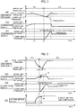
- Fig. 2 is a diagram for describing the operating number increase control that is a premise of this example.
- Fig. 2 is processing of increasing the number of compressor bodies to be operated when the amount of used air is increased and the amount of air is insufficient even after an increase in operating frequency.
- (a) illustrates the discharge pressure of the gas compressor over time (hereinafter, the discharge pressure of the gas compressor, that is, the discharge pressure in the main discharge pipe will be simply referred to as the discharge pressure unless otherwise specified)
- (b) and (c) illustrate the driving frequencies of the motors of compressor bodies 1 and 2 (hereinafter, referred to as the driving frequencies of the compressor bodies) over time.
- the driving frequencies of the compressor bodies the driving frequencies of the compressor bodies
- the compressor body 2 in Fig. 2 is a following machine is a case where the discharge pressure of the gas compressor is controlled to become constant by PID control in a period TP1 by the inverter-based rotational speed control only in the main machine.
- the driving frequency of the compressor body 1 is controlled to be raised by the inverter-based rotational speed control.
- an upper limit frequency is reached at time T1
- the frequency cannot be further raised, and thus the discharge pressure of the gas compressor decreases.
- the discharge pressure reaches a lower limit pressure at time T2
- processing for increasing the number of compressor bodies to be operated is performed.
- the discharge pressure by the compressor body 2 is increased by a command value being issued with respect to the compressor body 2 and the driving frequency of the compressor body 2 being increased.
- the inverter-based rotational speed control on the compressor body 2 is not in time, the discharge pressure of the compressor does not rise more than necessary, the amount of generated compressed air is less than the amount of used compressed air, the discharge pressure is less than the lower limit pressure value, and pressure undershoot occurs.
- Fig. 3 is a diagram for describing the operating number increase control in this example.
- the conditions in Fig. 3 are the same as those in Fig. 2.
- Fig. 3 differs from Fig. 2 in that the amount of air consumption is illustrated in (d) and the temporal changing amount of the discharge pressure, that is, an inclination Td is obtained at time T3, when the driving frequency of the compressor body 1 is being increased but has not reached the upper limit frequency, in (b) and (c).
- Equation (1) is calculated.
- P0 is a measurement pressure
- P0(t - 1) is the measurement pressure at the preceding second.
- Fig. 4 is the processing flow of the operating number increase control in this example.
- Step S10 it is determined first in Step S10 whether a driving frequency f0 of the operating compressor body is equal to or higher than a specified frequency.
- Step S11 it is determined whether the ratio to a maximum driving frequency fmax(P) defined by the pressure exceeds an operating number increase determination driving frequency ratio Rf.
- the processing proceeds to S11 in the case of, for example, 90% or more.
- Step S11 it is determined whether the discharge pressure P0 is equal to or less than a target control pressure Pt and the pressure is decreasing.
- the remaining discharge capacity is calculated in Step S13.
- Formula (2) is calculated. [Formula 2] 1 ⁇ f o f max P ⁇ q Po ⁇ n
- q(P) is the amount of discharged air per compressor and n is the number of operating units.
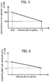
- the discharged air amount q(P) per compressor has the characteristic that is illustrated in Fig. 5 . In other words, the amount monotonically decreases as the pressure P0 increases.
- Step S14 the amount of insufficient air is calculated in Step S14. Specifically, Formula (3) is calculated. [Formula 3] dP dt ⁇ k Po ⁇ n
- k(P) is the insufficient air amount per unit pressure gradient (-0.01 MPa/s).
- the insufficient air amount k(P) per unit pressure gradient has the characteristic that is illustrated in Fig. 6 . In other words, the amount monotonically decreases as the pressure P0 increases.
- Step S15 an excess/deficiency determination on the remaining capacity is made. In other words, it is determined whether the remaining discharge capacity obtained in Step S13 is smaller than the insufficient air amount obtained in Step S14. Then, when the remaining discharge capacity is smaller than the insufficient air amount, the number of compressor bodies to be operated is increased in Step S16. In addition, when the remaining discharge capacity is larger than the insufficient air amount, the processing proceeds to Step S17 and the rotational speed of the motor is increased by the driving frequency of the compressor body being increased.
- Step S11 P0 is not equal to or less than the target control pressure Pt and the pressure is not decreasing. Accordingly, the processing proceeds to S17 and the rotational speed of the motor is reduced by the driving frequency of the compressor body being lowered.
- Step S10 the driving frequency f0 is within the specified frequency. Accordingly, the processing proceeds to S19 and normal rotational speed control is performed.
- the driving frequency of the compressor body is increased in Step S20.
- the driving frequency of the compressor body is lowered in Step S21.
- the driving frequency of the additionally operated compressor body is increased by the inverter control, the rotational speed of the motor that drives the compressor body is increased, and the discharge pressure of the gas compressor is controlled to become constant by PID control and the inverter-based rotational speed control.
- control delay occurs until the pressure becomes constant. Accordingly, if the next operating number increase control is performed immediately after, for example, the number of operating units is increased, the operating number increase control will be performed by means of the driving frequency of the compressor body or the discharge pressure in a transient state. It is conceivable that malfunction will arise in this case.
- next operating number increase control is not performed until a predetermined time elapses.
- next operating number increase control is performed after it is confirmed that the rotational speed of the motor that drives the compressor body reaches a steady value.
- the present invention is not limited to the examples and includes various modification examples.
- the examples have been described in detail so that the present invention is described in an easy-to-understand manner and are not necessarily limited to those having all the described configurations.
- another configuration can be added, deleted, and replaced with respect to a part of the configuration of each example.
Landscapes
- Engineering & Computer Science (AREA)
- Mechanical Engineering (AREA)
- General Engineering & Computer Science (AREA)
- Physics & Mathematics (AREA)
- Thermal Sciences (AREA)
- Computer Hardware Design (AREA)
- Control Of Positive-Displacement Pumps (AREA)
- Control Of Positive-Displacement Air Blowers (AREA)
Abstract
Description
- The present invention relates to a gas compressor. More particularly, the present invention relates to a method for controlling a gas compressor including a plurality of compressor bodies.
-
Patent Document 1 is a background art of a method for controlling a compressor including a plurality of compressor bodies. According toPatent Document 1, the compressor includes the plurality of compressor bodies disposed in parallel and subjected to rotational speed control by an inverter and one main discharge flow path where the discharge flow paths of the compressor bodies are merged. According to the compressor operation method described inPatent Document 1 for controlling the discharge pressure in the main discharge flow path to be kept constant, the rotational speed control is equally performed at all times with respect to every operating compressor body for discharge pressure adjustment. In addition, the operating compressor bodies are decreased in number when compressed gas supply to the main discharge flow path is excessive and it is enough to decrease the operating compressor bodies by one in number. The number is increased by one when the compressed gas supply is insufficient even after full-load operation of the operating compressor bodies. - Patent Document 1:
JP 2002-122078 A - In
Patent Document 1, the discharge pressure of the compressor is controlled by the inverter-based rotational speed control. When the discharge pressure decreases and is lower than a target value pressure as the amount of used air increases, a command rotational speed signal that causes the inverter to increase the rotational speed of the motor is output. However, the discharge pressure decreases when the amount of compressed air is undersupplied even after the full-load operation of the compressor body. Accordingly, when the number of operating compressor bodies is N and the detected discharge pressure is lower than a predetermined lower limit set pressure, number control is performed such that the number of compressor bodies to be operated is unconditionally added. However, the delay time of pressure increase and decrease is not taken into account, and thus nothing is taken into account as to the problem that a sharp increase in the amount of used air leads to control delay or pressure undershoot, that is, a more-than-necessary decrease in the discharge pressure of the compressor. - The present invention has been made in view of the problems, and an object of the present invention is to provide a gas compressor that can achieve reduced fluctuation of discharge pressure during compressor body number control, and a method for controlling the gas compressor.
- The present invention is in view of the background art and problems described above. In one example of the present invention, a gas compressor includes a plurality of compressor units each having a compressor body, a motor for driving the compressor body, and an inverter for controlling a rotational speed of the motor, and a control device for controlling each of the inverters. Discharge pipes of the compressor bodies are merged with one main discharge pipe. Discharge pressure of the main discharge pipe is controlled through control of pressure of the respective discharge pipes by controlling, by means of the respective inverters, driving frequencies of the compressor bodies. The control device determines whether recovery through an increase in the driving frequency of the motor of each of the compressor bodies is possible, on the basis of the pressure value and a temporal changing amount of the discharge pressure of the main discharge pipe when the driving frequency of the motor of the compressor body is being increased but has not reached an upper limit frequency, and controls an increase of the number of the compressor bodies to be operated.
- According to the present invention, it is possible to provide a gas compressor that can achieve reduced fluctuation of discharge pressure during compressor body number control, and a method for controlling the gas compressor.
-
-
Fig. 1 is a rear perspective view of a gas compressor in Example 1. -
Fig. 2 is a diagram for describing the operating number increase control that is a premise of Example 1. -
Fig. 3 is a diagram for describing the operating number increase control in Example 1. -
Fig. 4 is a processing flow chart of the operating number increase control in Example 1. -
Fig. 5 is a graph for describing the characteristic of a discharged air amount q(P) per compressor in Example 1. -
Fig. 6 is a diagram for describing the characteristic of an insufficient air amount k(P) per unit pressure gradient in Example 1. - Hereinafter, examples of the present invention will be described with reference to the drawings.
- The gas compressor in this example is premised on a gas compressor equipped with a plurality of compressor bodies. In addition, in this example, a gas compressor that compresses air will be described as an example.
-
Fig. 1 is a rear perspective view of the gas compressor in this example.Fig. 1 illustrates a state where aback panel 30, aside panel 31, and atop panel 32 are removed. As illustrated inFig. 1 , in this example, the gas compressor includes three stages of compressor units. The compressor units includecompressor bodies inverters compressor bodies inverters -
Fig. 2 is a diagram for describing the operating number increase control that is a premise of this example.Fig. 2 is processing of increasing the number of compressor bodies to be operated when the amount of used air is increased and the amount of air is insufficient even after an increase in operating frequency. InFig. 2 , (a) illustrates the discharge pressure of the gas compressor over time (hereinafter, the discharge pressure of the gas compressor, that is, the discharge pressure in the main discharge pipe will be simply referred to as the discharge pressure unless otherwise specified) and (b) and (c) illustrate the driving frequencies of the motors ofcompressor bodies 1 and 2 (hereinafter, referred to as the driving frequencies of the compressor bodies) over time. Assumed when thecompressor body 1 inFig. 2 is a main machine and thecompressor body 2 inFig. 2 is a following machine is a case where the discharge pressure of the gas compressor is controlled to become constant by PID control in a period TP1 by the inverter-based rotational speed control only in the main machine. Here, when the used air amount has increased, the driving frequency of thecompressor body 1 is controlled to be raised by the inverter-based rotational speed control. Then, when an upper limit frequency is reached at time T1, the frequency cannot be further raised, and thus the discharge pressure of the gas compressor decreases. Then, when the discharge pressure reaches a lower limit pressure at time T2, processing for increasing the number of compressor bodies to be operated is performed. In other words, the discharge pressure by thecompressor body 2 is increased by a command value being issued with respect to thecompressor body 2 and the driving frequency of thecompressor body 2 being increased. - Here, in the case of a sharp increase in the amount of used air, the inverter-based rotational speed control on the
compressor body 2 is not in time, the discharge pressure of the compressor does not rise more than necessary, the amount of generated compressed air is less than the amount of used compressed air, the discharge pressure is less than the lower limit pressure value, and pressure undershoot occurs. - In this regard, in this example, it is determined whether recovery through an increase in the driving frequency of each of the compressor bodies is possible, on the basis of the pressure value and the temporal changing amount of the discharge pressure when the driving frequency of the compressor body is being increased but has not reached the upper limit frequency, and an increase of the number of compressor bodies to be operated is controlled.
-
Fig. 3 is a diagram for describing the operating number increase control in this example. The conditions inFig. 3 are the same as those inFig. 2. Fig. 3 differs fromFig. 2 in that the amount of air consumption is illustrated in (d) and the temporal changing amount of the discharge pressure, that is, an inclination Td is obtained at time T3, when the driving frequency of thecompressor body 1 is being increased but has not reached the upper limit frequency, in (b) and (c). In other words, Equation (1) is calculated.
[Equation 1]
- Here, P0 is a measurement pressure and P0(t - 1) is the measurement pressure at the preceding second.
- Then, whether an air consumption amount kp can be recovered by a possible increase fp in the driving frequency of the compressor body is determined from the inclination Td of the discharge pressure and the discharge pressure value P0 and an increase of the number of compressor bodies to be operated is controlled. In other words, the number of compressor bodies to be operated is increased when the remaining discharge capacity is less than the amount of insufficient air. As a result, a drop in pressure can be suppressed early and it is possible to prevent a drop in discharge pressure attributable to a sharp increase in the amount of used air.
-
Fig. 4 is the processing flow of the operating number increase control in this example. InFig. 4 , it is determined first in Step S10 whether a driving frequency f0 of the operating compressor body is equal to or higher than a specified frequency. Here, it is determined whether the ratio to a maximum driving frequency fmax(P) defined by the pressure exceeds an operating number increase determination driving frequency ratio Rf. The processing proceeds to S11 in the case of, for example, 90% or more. In Step S11, it is determined whether the discharge pressure P0 is equal to or less than a target control pressure Pt and the pressure is decreasing. In the case of Yes, the processing proceeds to S12 and the inclination of the discharge pressure, that is, the pressure gradient dP/dt = (Po - Po(t - 1))/dt, which is the temporal changing amount, is calculated. In addition, the remaining discharge capacity is calculated in Step S13. Specifically, Formula (2) is calculated.
[Formula 2]
- Here, q(P) is the amount of discharged air per compressor and n is the number of operating units.
- It should be noted that the discharged air amount q(P) per compressor has the characteristic that is illustrated in
Fig. 5 . In other words, the amount monotonically decreases as the pressure P0 increases. - Next, the amount of insufficient air is calculated in Step S14. Specifically, Formula (3) is calculated.
[Formula 3]
- Here, k(P) is the insufficient air amount per unit pressure gradient (-0.01 MPa/s).
- It should be noted that the insufficient air amount k(P) per unit pressure gradient has the characteristic that is illustrated in
Fig. 6 . In other words, the amount monotonically decreases as the pressure P0 increases. - Then, in Step S15, an excess/deficiency determination on the remaining capacity is made. In other words, it is determined whether the remaining discharge capacity obtained in Step S13 is smaller than the insufficient air amount obtained in Step S14. Then, when the remaining discharge capacity is smaller than the insufficient air amount, the number of compressor bodies to be operated is increased in Step S16. In addition, when the remaining discharge capacity is larger than the insufficient air amount, the processing proceeds to Step S17 and the rotational speed of the motor is increased by the driving frequency of the compressor body being increased.
- In the case of No in Step S11, P0 is not equal to or less than the target control pressure Pt and the pressure is not decreasing. Accordingly, the processing proceeds to S17 and the rotational speed of the motor is reduced by the driving frequency of the compressor body being lowered.
- In addition, in the case of No in Step S10, the driving frequency f0 is within the specified frequency. Accordingly, the processing proceeds to S19 and normal rotational speed control is performed. When the discharge pressure P0 is equal to or lower than the target control pressure Pt, the driving frequency of the compressor body is increased in Step S20. When the discharge pressure P0 is not equal to or lower than the target control pressure Pt, the driving frequency of the compressor body is lowered in Step S21.
- When the processing described above is completed, the first return is made in Step S22 and the processing described above is repeated.
- As described above, according to this example, it is determined whether recovery through an increase in the driving frequency of each of the compressor bodies is possible, on the basis of the pressure value and the temporal changing amount of the discharge pressure of the main discharge pipe when the driving frequency of the compressor body is being increased but has not reached the upper limit frequency, and an increase of the number of compressor bodies to be operated is controlled. Accordingly, it is possible to suppress the occurrence of control delay or pressure undershoot that causes the discharge pressure of the compressor to decrease more than necessary in the case of a sharp increase in the amount of used air and it is possible to provide a gas compressor that can achieve reduced fluctuation of discharge pressure during compressor body number control, and a method for controlling the gas compressor.
- In this example, an example will be described in which the inconvenience in a case where the operating number increase control is further performed immediately after an increase in the number of operating units is suppressed.
- Immediately after the number of operating units is increased by the operating number increase control in Example 1 being performed, the driving frequency of the additionally operated compressor body is increased by the inverter control, the rotational speed of the motor that drives the compressor body is increased, and the discharge pressure of the gas compressor is controlled to become constant by PID control and the inverter-based rotational speed control. Here, control delay occurs until the pressure becomes constant. Accordingly, if the next operating number increase control is performed immediately after, for example, the number of operating units is increased, the operating number increase control will be performed by means of the driving frequency of the compressor body or the discharge pressure in a transient state. It is conceivable that malfunction will arise in this case.
- In this regard, immediately after an increase of the number of compressor bodies to be operated, the next operating number increase control is not performed until a predetermined time elapses. In addition, immediately after an increase of the number of compressor bodies to be operated, the next operating number increase control is performed after it is confirmed that the rotational speed of the motor that drives the compressor body reaches a steady value.
- As a result, it is possible to suppress the execution of the operating number increase control that uses the driving frequency of the compressor body or the discharge pressure in the transient state immediately following an increase in the number of operating units and malfunction can be prevented.
- Although examples have been described above, the present invention is not limited to the examples and includes various modification examples. For example, the examples have been described in detail so that the present invention is described in an easy-to-understand manner and are not necessarily limited to those having all the described configurations. In addition, it is possible to replace a part of the configuration of one example with the configuration of another example and to add the configuration of another example to the configuration of one example. In addition, another configuration can be added, deleted, and replaced with respect to a part of the configuration of each example.
-
- 10, 11, 12
- Compressor body
- 20, 21, 22
- Inverter
- 30
- Back panel
- 31
- Side panel
- 32
- Top panel
Claims (8)
- A gas compressor comprising:a plurality of compressor units each including a compressor body, a motor for driving the compressor body, and an inverter for controlling a rotational speed of the motor; anda control device for controlling each of the inverters, whereindischarge pipes of the compressor bodies are merged with one main discharge pipe and discharge pressure of the main discharge pipe is controlled through control of pressure of the respective discharge pipes by controlling, by means of the respective inverters, driving frequencies of the motors of the compressor bodies, andthe control device determines whether recovery through an increase in the driving frequency of the motor of each of the compressor bodies is possible, on the basis of the pressure value and a temporal changing amount of the discharge pressure of the main discharge pipe when the driving frequency of the motor of the compressor body is being increased but has not reached an upper limit frequency, and controls an increase of the number of the compressor bodies to be operated.
- The gas compressor according to claim 1,
wherein the control device calculates an insufficient gas amount and a remaining discharge capacity of the compressor body from the temporal changing amount of the discharge pressure and the pressure value and the control device causes the number of the compressor bodies to be operated to increase when the remaining discharge capacity is smaller than the insufficient gas amount. - The gas compressor according to claim 1,
wherein the control device performs next control of an increase of the number of the compressor bodies to be operated after a predetermined time has elapsed immediately after causing the number of the compressor bodies to be operated to increase. - The gas compressor according to claim 1,
wherein the control device performs next control of an increase of the number of the compressor bodies to be operated after confirming that the rotational speed of the motor reaches a steady value immediately after causing the number of the compressor bodies to be operated to increase. - A method for controlling a gas compressor including a plurality of compressor units each having a compressor body, a motor for driving the compressor body, and an inverter for controlling a rotational speed of the motor, discharge pipes of the compressor bodies being merged with one main discharge pipe, and discharge pressure of the main discharge pipe being controlled through control of driving frequencies of the compressor bodies, wherein
whether recovery through an increase in the driving frequency of the motor of each of the compressor bodies is possible is determined, on the basis of the pressure value and a temporal changing amount of the discharge pressure of the main discharge pipe when the driving frequency of the motor of the compressor body is being increased but has not reached an upper limit frequency, and an increase of the number of the compressor bodies to be operated is controlled. - The gas compressor control method according to claim 5,
wherein an insufficient gas amount and a remaining discharge capacity of the compressor body are calculated from the temporal changing amount of the discharge pressure and the pressure value and the number of the compressor bodies to be operated is increased when the remaining discharge capacity is smaller than the insufficient gas amount. - The gas compressor control method according to claim 5,
wherein next control of an increase of the number of the compressor bodies to be operated is performed after a predetermined time has elapsed immediately after the number of the compressor bodies to be operated is increased. - The gas compressor control method according to claim 5,
wherein next control of an increase of the number of the compressor bodies to be operated is performed after it is confirmed that the rotational speed of the motor reaches a steady value immediately after the number of the compressor bodies to be operated is increased.
Applications Claiming Priority (2)
| Application Number | Priority Date | Filing Date | Title |
|---|---|---|---|
| JP2018181426 | 2018-09-27 | ||
| PCT/JP2019/029510 WO2020066267A1 (en) | 2018-09-27 | 2019-07-26 | Gas compressor and method for controlling same |
Publications (3)
| Publication Number | Publication Date |
|---|---|
| EP3859155A1 true EP3859155A1 (en) | 2021-08-04 |
| EP3859155A4 EP3859155A4 (en) | 2022-07-06 |
| EP3859155B1 EP3859155B1 (en) | 2024-09-18 |
Family
ID=69949329
Family Applications (1)
| Application Number | Title | Priority Date | Filing Date |
|---|---|---|---|
| EP19868013.4A Active EP3859155B1 (en) | 2018-09-27 | 2019-07-26 | Gas compressor and method for controlling same |
Country Status (5)
| Country | Link |
|---|---|
| US (1) | US11585335B2 (en) |
| EP (1) | EP3859155B1 (en) |
| JP (1) | JP7035208B2 (en) |
| CN (1) | CN111771057B (en) |
| WO (1) | WO2020066267A1 (en) |
Families Citing this family (1)
| Publication number | Priority date | Publication date | Assignee | Title |
|---|---|---|---|---|
| US12098722B2 (en) * | 2022-05-24 | 2024-09-24 | Haier Us Appliance Solutions, Inc. | Method for determining a discharge pressure of a rolling piston compressor |
Family Cites Families (8)
| Publication number | Priority date | Publication date | Assignee | Title |
|---|---|---|---|---|
| CN1068175A (en) * | 1992-07-16 | 1993-01-20 | 北京科日达电子技术有限公司 | Constant pressure variable control system for fully automatic air compression station |
| JP3404492B2 (en) * | 1998-04-02 | 2003-05-06 | 株式会社日立産機システム | Compressor operation control method and compressor operation control device |
| JP4043184B2 (en) | 2000-10-13 | 2008-02-06 | 株式会社神戸製鋼所 | Compressor control method |
| JP4069450B2 (en) * | 2003-06-24 | 2008-04-02 | 日立工機株式会社 | Air compressor and control method thereof |
| JP5913811B2 (en) * | 2011-01-18 | 2016-04-27 | 株式会社Ihi回転機械 | Compressor number control device and compressor number control method using the same |
| CN104968939B (en) | 2013-02-08 | 2018-01-09 | 株式会社日立产机系统 | Fluid compression system and its control device |
| JP6014508B2 (en) * | 2013-02-08 | 2016-10-25 | 株式会社日立産機システム | Fluid compression system |
| JP6539319B2 (en) * | 2017-08-28 | 2019-07-03 | 株式会社日立産機システム | Fluid compression system or controller thereof |
-
2019
- 2019-07-26 JP JP2020548070A patent/JP7035208B2/en active Active
- 2019-07-26 WO PCT/JP2019/029510 patent/WO2020066267A1/en not_active Ceased
- 2019-07-26 EP EP19868013.4A patent/EP3859155B1/en active Active
- 2019-07-26 US US16/977,870 patent/US11585335B2/en active Active
- 2019-07-26 CN CN201980015787.XA patent/CN111771057B/en active Active
Also Published As
| Publication number | Publication date |
|---|---|
| EP3859155B1 (en) | 2024-09-18 |
| WO2020066267A1 (en) | 2020-04-02 |
| EP3859155A4 (en) | 2022-07-06 |
| CN111771057A (en) | 2020-10-13 |
| US20210025380A1 (en) | 2021-01-28 |
| JPWO2020066267A1 (en) | 2021-02-18 |
| JP7035208B2 (en) | 2022-03-14 |
| US11585335B2 (en) | 2023-02-21 |
| CN111771057B (en) | 2022-08-23 |
Similar Documents
| Publication | Publication Date | Title |
|---|---|---|
| EP1965083A1 (en) | Hydraulic unit and method of controlling speed of motor in hydraulic unit | |
| EP2813776B1 (en) | method and controller for an air conditioning system | |
| EP2288859B1 (en) | Method of controlling an air cooled heat exchanger | |
| JP4699130B2 (en) | Gas turbine inlet guide vane control device | |
| EP2998659B1 (en) | Method for controlling outdoor fan motor of air conditioner | |
| US9964047B2 (en) | Gas turbine engine optimization control device | |
| CN111271900B (en) | Compressor oil return control method, system and air conditioner | |
| EP3859155A1 (en) | Gas compressor and method for controlling same | |
| EP4450813B1 (en) | Dual pump smart control system | |
| CN114094145A (en) | Vehicle-mounted fuel cell boosting DCDC control method and system | |
| US6680592B2 (en) | Method and apparatus for producing current values dependent on the position of the accelerator pedal for the purpose of controlling the power of one or more drives in a mobile device with a fuel cell for supplying energy | |
| CN113915112B (en) | Unit variable frequency compressor control method and device and condensing unit | |
| EP1548236A2 (en) | Two-shaft gas turbine control method, two-shaft gas turbine, and two-shaft gas turbine control system | |
| EP2918933A1 (en) | Heat source system control device | |
| EP3885669A1 (en) | Method for controlling a refrigerant circuit by determining the supply voltage of a fan coupled with a condenser of the refrigerant circuit | |
| EP3859156A1 (en) | Gas compressor and control method therefor | |
| US8295954B2 (en) | Method and device for adjusting a regulating device | |
| JP2020143641A (en) | Compressor pressure control method and pressure control device | |
| KR101864321B1 (en) | Fluid compressor control system | |
| JP5888947B2 (en) | Valve control device, gas turbine, and valve control method | |
| JP2538675B2 (en) | Inverter operating frequency control method | |
| WO2020039467A1 (en) | Device for controlling pump system for descaling apparatus | |
| JP5108477B2 (en) | Engine driven compressor | |
| CN110486903A (en) | The control method and system of loaded self-adaptive when a kind of frequency-variable controller closed-loop start-up | |
| JP2024022294A (en) | compressor system |
Legal Events
| Date | Code | Title | Description |
|---|---|---|---|
| STAA | Information on the status of an ep patent application or granted ep patent |
Free format text: STATUS: THE INTERNATIONAL PUBLICATION HAS BEEN MADE |
|
| PUAI | Public reference made under article 153(3) epc to a published international application that has entered the european phase |
Free format text: ORIGINAL CODE: 0009012 |
|
| STAA | Information on the status of an ep patent application or granted ep patent |
Free format text: STATUS: REQUEST FOR EXAMINATION WAS MADE |
|
| 17P | Request for examination filed |
Effective date: 20210428 |
|
| AK | Designated contracting states |
Kind code of ref document: A1 Designated state(s): AL AT BE BG CH CY CZ DE DK EE ES FI FR GB GR HR HU IE IS IT LI LT LU LV MC MK MT NL NO PL PT RO RS SE SI SK SM TR |
|
| DAV | Request for validation of the european patent (deleted) | ||
| DAX | Request for extension of the european patent (deleted) | ||
| A4 | Supplementary search report drawn up and despatched |
Effective date: 20220603 |
|
| RIC1 | Information provided on ipc code assigned before grant |
Ipc: F04B 49/06 20060101AFI20220530BHEP |
|
| GRAP | Despatch of communication of intention to grant a patent |
Free format text: ORIGINAL CODE: EPIDOSNIGR1 |
|
| STAA | Information on the status of an ep patent application or granted ep patent |
Free format text: STATUS: GRANT OF PATENT IS INTENDED |
|
| INTG | Intention to grant announced |
Effective date: 20240430 |
|
| GRAS | Grant fee paid |
Free format text: ORIGINAL CODE: EPIDOSNIGR3 |
|
| GRAA | (expected) grant |
Free format text: ORIGINAL CODE: 0009210 |
|
| STAA | Information on the status of an ep patent application or granted ep patent |
Free format text: STATUS: THE PATENT HAS BEEN GRANTED |
|
| AK | Designated contracting states |
Kind code of ref document: B1 Designated state(s): AL AT BE BG CH CY CZ DE DK EE ES FI FR GB GR HR HU IE IS IT LI LT LU LV MC MK MT NL NO PL PT RO RS SE SI SK SM TR |
|
| REG | Reference to a national code |
Ref country code: GB Ref legal event code: FG4D |
|
| REG | Reference to a national code |
Ref country code: CH Ref legal event code: EP |
|
| REG | Reference to a national code |
Ref country code: IE Ref legal event code: FG4D |
|
| REG | Reference to a national code |
Ref country code: DE Ref legal event code: R096 Ref document number: 602019059235 Country of ref document: DE |
|
| REG | Reference to a national code |
Ref country code: LT Ref legal event code: MG9D |
|
| PG25 | Lapsed in a contracting state [announced via postgrant information from national office to epo] |
Ref country code: NO Free format text: LAPSE BECAUSE OF FAILURE TO SUBMIT A TRANSLATION OF THE DESCRIPTION OR TO PAY THE FEE WITHIN THE PRESCRIBED TIME-LIMIT Effective date: 20241218 |
|
| PG25 | Lapsed in a contracting state [announced via postgrant information from national office to epo] |
Ref country code: GR Free format text: LAPSE BECAUSE OF FAILURE TO SUBMIT A TRANSLATION OF THE DESCRIPTION OR TO PAY THE FEE WITHIN THE PRESCRIBED TIME-LIMIT Effective date: 20241219 Ref country code: FI Free format text: LAPSE BECAUSE OF FAILURE TO SUBMIT A TRANSLATION OF THE DESCRIPTION OR TO PAY THE FEE WITHIN THE PRESCRIBED TIME-LIMIT Effective date: 20240918 |
|
| PG25 | Lapsed in a contracting state [announced via postgrant information from national office to epo] |
Ref country code: BG Free format text: LAPSE BECAUSE OF FAILURE TO SUBMIT A TRANSLATION OF THE DESCRIPTION OR TO PAY THE FEE WITHIN THE PRESCRIBED TIME-LIMIT Effective date: 20240918 |
|
| PG25 | Lapsed in a contracting state [announced via postgrant information from national office to epo] |
Ref country code: LV Free format text: LAPSE BECAUSE OF FAILURE TO SUBMIT A TRANSLATION OF THE DESCRIPTION OR TO PAY THE FEE WITHIN THE PRESCRIBED TIME-LIMIT Effective date: 20240918 |
|
| PG25 | Lapsed in a contracting state [announced via postgrant information from national office to epo] |
Ref country code: HR Free format text: LAPSE BECAUSE OF FAILURE TO SUBMIT A TRANSLATION OF THE DESCRIPTION OR TO PAY THE FEE WITHIN THE PRESCRIBED TIME-LIMIT Effective date: 20240918 |
|
| REG | Reference to a national code |
Ref country code: NL Ref legal event code: MP Effective date: 20240918 |
|
| PG25 | Lapsed in a contracting state [announced via postgrant information from national office to epo] |
Ref country code: RS Free format text: LAPSE BECAUSE OF FAILURE TO SUBMIT A TRANSLATION OF THE DESCRIPTION OR TO PAY THE FEE WITHIN THE PRESCRIBED TIME-LIMIT Effective date: 20241218 |
|
| PG25 | Lapsed in a contracting state [announced via postgrant information from national office to epo] |
Ref country code: RS Free format text: LAPSE BECAUSE OF FAILURE TO SUBMIT A TRANSLATION OF THE DESCRIPTION OR TO PAY THE FEE WITHIN THE PRESCRIBED TIME-LIMIT Effective date: 20241218 Ref country code: NO Free format text: LAPSE BECAUSE OF FAILURE TO SUBMIT A TRANSLATION OF THE DESCRIPTION OR TO PAY THE FEE WITHIN THE PRESCRIBED TIME-LIMIT Effective date: 20241218 Ref country code: LV Free format text: LAPSE BECAUSE OF FAILURE TO SUBMIT A TRANSLATION OF THE DESCRIPTION OR TO PAY THE FEE WITHIN THE PRESCRIBED TIME-LIMIT Effective date: 20240918 Ref country code: HR Free format text: LAPSE BECAUSE OF FAILURE TO SUBMIT A TRANSLATION OF THE DESCRIPTION OR TO PAY THE FEE WITHIN THE PRESCRIBED TIME-LIMIT Effective date: 20240918 Ref country code: GR Free format text: LAPSE BECAUSE OF FAILURE TO SUBMIT A TRANSLATION OF THE DESCRIPTION OR TO PAY THE FEE WITHIN THE PRESCRIBED TIME-LIMIT Effective date: 20241219 Ref country code: FI Free format text: LAPSE BECAUSE OF FAILURE TO SUBMIT A TRANSLATION OF THE DESCRIPTION OR TO PAY THE FEE WITHIN THE PRESCRIBED TIME-LIMIT Effective date: 20240918 Ref country code: BG Free format text: LAPSE BECAUSE OF FAILURE TO SUBMIT A TRANSLATION OF THE DESCRIPTION OR TO PAY THE FEE WITHIN THE PRESCRIBED TIME-LIMIT Effective date: 20240918 |
|
| REG | Reference to a national code |
Ref country code: AT Ref legal event code: MK05 Ref document number: 1724886 Country of ref document: AT Kind code of ref document: T Effective date: 20240918 |
|
| PG25 | Lapsed in a contracting state [announced via postgrant information from national office to epo] |
Ref country code: NL Free format text: LAPSE BECAUSE OF FAILURE TO SUBMIT A TRANSLATION OF THE DESCRIPTION OR TO PAY THE FEE WITHIN THE PRESCRIBED TIME-LIMIT Effective date: 20240918 |
|
| PG25 | Lapsed in a contracting state [announced via postgrant information from national office to epo] |
Ref country code: IS Free format text: LAPSE BECAUSE OF FAILURE TO SUBMIT A TRANSLATION OF THE DESCRIPTION OR TO PAY THE FEE WITHIN THE PRESCRIBED TIME-LIMIT Effective date: 20250118 Ref country code: PT Free format text: LAPSE BECAUSE OF FAILURE TO SUBMIT A TRANSLATION OF THE DESCRIPTION OR TO PAY THE FEE WITHIN THE PRESCRIBED TIME-LIMIT Effective date: 20250120 |
|
| PG25 | Lapsed in a contracting state [announced via postgrant information from national office to epo] |
Ref country code: RO Free format text: LAPSE BECAUSE OF FAILURE TO SUBMIT A TRANSLATION OF THE DESCRIPTION OR TO PAY THE FEE WITHIN THE PRESCRIBED TIME-LIMIT Effective date: 20240918 Ref country code: SM Free format text: LAPSE BECAUSE OF FAILURE TO SUBMIT A TRANSLATION OF THE DESCRIPTION OR TO PAY THE FEE WITHIN THE PRESCRIBED TIME-LIMIT Effective date: 20240918 |
|
| PG25 | Lapsed in a contracting state [announced via postgrant information from national office to epo] |
Ref country code: ES Free format text: LAPSE BECAUSE OF FAILURE TO SUBMIT A TRANSLATION OF THE DESCRIPTION OR TO PAY THE FEE WITHIN THE PRESCRIBED TIME-LIMIT Effective date: 20240918 |
|
| PG25 | Lapsed in a contracting state [announced via postgrant information from national office to epo] |
Ref country code: EE Free format text: LAPSE BECAUSE OF FAILURE TO SUBMIT A TRANSLATION OF THE DESCRIPTION OR TO PAY THE FEE WITHIN THE PRESCRIBED TIME-LIMIT Effective date: 20240918 Ref country code: AT Free format text: LAPSE BECAUSE OF FAILURE TO SUBMIT A TRANSLATION OF THE DESCRIPTION OR TO PAY THE FEE WITHIN THE PRESCRIBED TIME-LIMIT Effective date: 20240918 |
|
| PG25 | Lapsed in a contracting state [announced via postgrant information from national office to epo] |
Ref country code: PL Free format text: LAPSE BECAUSE OF FAILURE TO SUBMIT A TRANSLATION OF THE DESCRIPTION OR TO PAY THE FEE WITHIN THE PRESCRIBED TIME-LIMIT Effective date: 20240918 Ref country code: CZ Free format text: LAPSE BECAUSE OF FAILURE TO SUBMIT A TRANSLATION OF THE DESCRIPTION OR TO PAY THE FEE WITHIN THE PRESCRIBED TIME-LIMIT Effective date: 20240918 |
|
| PG25 | Lapsed in a contracting state [announced via postgrant information from national office to epo] |
Ref country code: IT Free format text: LAPSE BECAUSE OF FAILURE TO SUBMIT A TRANSLATION OF THE DESCRIPTION OR TO PAY THE FEE WITHIN THE PRESCRIBED TIME-LIMIT Effective date: 20240918 Ref country code: SK Free format text: LAPSE BECAUSE OF FAILURE TO SUBMIT A TRANSLATION OF THE DESCRIPTION OR TO PAY THE FEE WITHIN THE PRESCRIBED TIME-LIMIT Effective date: 20240918 |
|
| REG | Reference to a national code |
Ref country code: DE Ref legal event code: R097 Ref document number: 602019059235 Country of ref document: DE |
|
| PG25 | Lapsed in a contracting state [announced via postgrant information from national office to epo] |
Ref country code: DK Free format text: LAPSE BECAUSE OF FAILURE TO SUBMIT A TRANSLATION OF THE DESCRIPTION OR TO PAY THE FEE WITHIN THE PRESCRIBED TIME-LIMIT Effective date: 20240918 |
|
| PLBE | No opposition filed within time limit |
Free format text: ORIGINAL CODE: 0009261 |
|
| STAA | Information on the status of an ep patent application or granted ep patent |
Free format text: STATUS: NO OPPOSITION FILED WITHIN TIME LIMIT |
|
| 26N | No opposition filed |
Effective date: 20250619 |
|
| PG25 | Lapsed in a contracting state [announced via postgrant information from national office to epo] |
Ref country code: SE Free format text: LAPSE BECAUSE OF FAILURE TO SUBMIT A TRANSLATION OF THE DESCRIPTION OR TO PAY THE FEE WITHIN THE PRESCRIBED TIME-LIMIT Effective date: 20240918 |
|
| PGFP | Annual fee paid to national office [announced via postgrant information from national office to epo] |
Ref country code: DE Payment date: 20250731 Year of fee payment: 7 |
|
| PGFP | Annual fee paid to national office [announced via postgrant information from national office to epo] |
Ref country code: BE Payment date: 20250722 Year of fee payment: 7 Ref country code: GB Payment date: 20250724 Year of fee payment: 7 |
|
| PGFP | Annual fee paid to national office [announced via postgrant information from national office to epo] |
Ref country code: FR Payment date: 20250723 Year of fee payment: 7 |
|
| REG | Reference to a national code |
Ref country code: CH Ref legal event code: H13 Free format text: ST27 STATUS EVENT CODE: U-0-0-H10-H13 (AS PROVIDED BY THE NATIONAL OFFICE) Effective date: 20260224 |
|
| PG25 | Lapsed in a contracting state [announced via postgrant information from national office to epo] |
Ref country code: LU Free format text: LAPSE BECAUSE OF NON-PAYMENT OF DUE FEES Effective date: 20250726 |
|
| PG25 | Lapsed in a contracting state [announced via postgrant information from national office to epo] |
Ref country code: CH Free format text: LAPSE BECAUSE OF NON-PAYMENT OF DUE FEES Effective date: 20250731 |