EP3858792A1 - Method and apparatus for direct drying of inorganic sludge with drum drawing process - Google Patents
Method and apparatus for direct drying of inorganic sludge with drum drawing process Download PDFInfo
- Publication number
- EP3858792A1 EP3858792A1 EP19866463.3A EP19866463A EP3858792A1 EP 3858792 A1 EP3858792 A1 EP 3858792A1 EP 19866463 A EP19866463 A EP 19866463A EP 3858792 A1 EP3858792 A1 EP 3858792A1
- Authority
- EP
- European Patent Office
- Prior art keywords
- sludge
- slag
- drum
- drying
- tail gas
- Prior art date
- Legal status (The legal status is an assumption and is not a legal conclusion. Google has not performed a legal analysis and makes no representation as to the accuracy of the status listed.)
- Granted
Links
Images
Classifications
-
- C—CHEMISTRY; METALLURGY
- C02—TREATMENT OF WATER, WASTE WATER, SEWAGE, OR SLUDGE
- C02F—TREATMENT OF WATER, WASTE WATER, SEWAGE, OR SLUDGE
- C02F11/00—Treatment of sludge; Devices therefor
- C02F11/12—Treatment of sludge; Devices therefor by de-watering, drying or thickening
-
- C—CHEMISTRY; METALLURGY
- C02—TREATMENT OF WATER, WASTE WATER, SEWAGE, OR SLUDGE
- C02F—TREATMENT OF WATER, WASTE WATER, SEWAGE, OR SLUDGE
- C02F11/00—Treatment of sludge; Devices therefor
- C02F11/12—Treatment of sludge; Devices therefor by de-watering, drying or thickening
- C02F11/13—Treatment of sludge; Devices therefor by de-watering, drying or thickening by heating
-
- C—CHEMISTRY; METALLURGY
- C02—TREATMENT OF WATER, WASTE WATER, SEWAGE, OR SLUDGE
- C02F—TREATMENT OF WATER, WASTE WATER, SEWAGE, OR SLUDGE
- C02F11/00—Treatment of sludge; Devices therefor
- C02F11/12—Treatment of sludge; Devices therefor by de-watering, drying or thickening
- C02F11/121—Treatment of sludge; Devices therefor by de-watering, drying or thickening by mechanical de-watering
- C02F11/126—Treatment of sludge; Devices therefor by de-watering, drying or thickening by mechanical de-watering using drum filters
-
- B—PERFORMING OPERATIONS; TRANSPORTING
- B01—PHYSICAL OR CHEMICAL PROCESSES OR APPARATUS IN GENERAL
- B01D—SEPARATION
- B01D53/00—Separation of gases or vapours; Recovering vapours of volatile solvents from gases; Chemical or biological purification of waste gases, e.g. engine exhaust gases, smoke, fumes, flue gases, aerosols
- B01D53/02—Separation of gases or vapours; Recovering vapours of volatile solvents from gases; Chemical or biological purification of waste gases, e.g. engine exhaust gases, smoke, fumes, flue gases, aerosols by adsorption, e.g. preparative gas chromatography
-
- B—PERFORMING OPERATIONS; TRANSPORTING
- B01—PHYSICAL OR CHEMICAL PROCESSES OR APPARATUS IN GENERAL
- B01D—SEPARATION
- B01D53/00—Separation of gases or vapours; Recovering vapours of volatile solvents from gases; Chemical or biological purification of waste gases, e.g. engine exhaust gases, smoke, fumes, flue gases, aerosols
- B01D53/02—Separation of gases or vapours; Recovering vapours of volatile solvents from gases; Chemical or biological purification of waste gases, e.g. engine exhaust gases, smoke, fumes, flue gases, aerosols by adsorption, e.g. preparative gas chromatography
- B01D53/04—Separation of gases or vapours; Recovering vapours of volatile solvents from gases; Chemical or biological purification of waste gases, e.g. engine exhaust gases, smoke, fumes, flue gases, aerosols by adsorption, e.g. preparative gas chromatography with stationary adsorbents
-
- B—PERFORMING OPERATIONS; TRANSPORTING
- B01—PHYSICAL OR CHEMICAL PROCESSES OR APPARATUS IN GENERAL
- B01D—SEPARATION
- B01D53/00—Separation of gases or vapours; Recovering vapours of volatile solvents from gases; Chemical or biological purification of waste gases, e.g. engine exhaust gases, smoke, fumes, flue gases, aerosols
- B01D53/14—Separation of gases or vapours; Recovering vapours of volatile solvents from gases; Chemical or biological purification of waste gases, e.g. engine exhaust gases, smoke, fumes, flue gases, aerosols by absorption
-
- B—PERFORMING OPERATIONS; TRANSPORTING
- B01—PHYSICAL OR CHEMICAL PROCESSES OR APPARATUS IN GENERAL
- B01D—SEPARATION
- B01D53/00—Separation of gases or vapours; Recovering vapours of volatile solvents from gases; Chemical or biological purification of waste gases, e.g. engine exhaust gases, smoke, fumes, flue gases, aerosols
- B01D53/34—Chemical or biological purification of waste gases
- B01D53/38—Removing components of undefined structure
- B01D53/44—Organic components
-
- B—PERFORMING OPERATIONS; TRANSPORTING
- B01—PHYSICAL OR CHEMICAL PROCESSES OR APPARATUS IN GENERAL
- B01D—SEPARATION
- B01D53/00—Separation of gases or vapours; Recovering vapours of volatile solvents from gases; Chemical or biological purification of waste gases, e.g. engine exhaust gases, smoke, fumes, flue gases, aerosols
- B01D53/34—Chemical or biological purification of waste gases
- B01D53/46—Removing components of defined structure
- B01D53/48—Sulfur compounds
-
- B—PERFORMING OPERATIONS; TRANSPORTING
- B01—PHYSICAL OR CHEMICAL PROCESSES OR APPARATUS IN GENERAL
- B01D—SEPARATION
- B01D53/00—Separation of gases or vapours; Recovering vapours of volatile solvents from gases; Chemical or biological purification of waste gases, e.g. engine exhaust gases, smoke, fumes, flue gases, aerosols
- B01D53/34—Chemical or biological purification of waste gases
- B01D53/46—Removing components of defined structure
- B01D53/72—Organic compounds not provided for in groups B01D53/48 - B01D53/70, e.g. hydrocarbons
-
- B—PERFORMING OPERATIONS; TRANSPORTING
- B01—PHYSICAL OR CHEMICAL PROCESSES OR APPARATUS IN GENERAL
- B01D—SEPARATION
- B01D53/00—Separation of gases or vapours; Recovering vapours of volatile solvents from gases; Chemical or biological purification of waste gases, e.g. engine exhaust gases, smoke, fumes, flue gases, aerosols
- B01D53/34—Chemical or biological purification of waste gases
- B01D53/74—General processes for purification of waste gases; Apparatus or devices specially adapted therefor
- B01D53/77—Liquid phase processes
- B01D53/78—Liquid phase processes with gas-liquid contact
-
- C—CHEMISTRY; METALLURGY
- C02—TREATMENT OF WATER, WASTE WATER, SEWAGE, OR SLUDGE
- C02F—TREATMENT OF WATER, WASTE WATER, SEWAGE, OR SLUDGE
- C02F11/00—Treatment of sludge; Devices therefor
- C02F11/12—Treatment of sludge; Devices therefor by de-watering, drying or thickening
- C02F11/14—Treatment of sludge; Devices therefor by de-watering, drying or thickening with addition of chemical agents
- C02F11/143—Treatment of sludge; Devices therefor by de-watering, drying or thickening with addition of chemical agents using inorganic substances
-
- C—CHEMISTRY; METALLURGY
- C21—METALLURGY OF IRON
- C21B—MANUFACTURE OF IRON OR STEEL
- C21B3/00—General features in the manufacture of pig-iron
- C21B3/04—Recovery of by-products, e.g. slag
- C21B3/06—Treatment of liquid slag
-
- C—CHEMISTRY; METALLURGY
- C21—METALLURGY OF IRON
- C21B—MANUFACTURE OF IRON OR STEEL
- C21B3/00—General features in the manufacture of pig-iron
- C21B3/04—Recovery of by-products, e.g. slag
- C21B3/06—Treatment of liquid slag
- C21B3/08—Cooling slag
-
- F—MECHANICAL ENGINEERING; LIGHTING; HEATING; WEAPONS; BLASTING
- F26—DRYING
- F26B—DRYING SOLID MATERIALS OR OBJECTS BY REMOVING LIQUID THEREFROM
- F26B11/00—Machines or apparatus for drying solid materials or objects with movement which is non-progressive
- F26B11/02—Machines or apparatus for drying solid materials or objects with movement which is non-progressive in moving drums or other mainly-closed receptacles
-
- F—MECHANICAL ENGINEERING; LIGHTING; HEATING; WEAPONS; BLASTING
- F26—DRYING
- F26B—DRYING SOLID MATERIALS OR OBJECTS BY REMOVING LIQUID THEREFROM
- F26B11/00—Machines or apparatus for drying solid materials or objects with movement which is non-progressive
- F26B11/02—Machines or apparatus for drying solid materials or objects with movement which is non-progressive in moving drums or other mainly-closed receptacles
- F26B11/04—Machines or apparatus for drying solid materials or objects with movement which is non-progressive in moving drums or other mainly-closed receptacles rotating about a horizontal or slightly-inclined axis
-
- F—MECHANICAL ENGINEERING; LIGHTING; HEATING; WEAPONS; BLASTING
- F26—DRYING
- F26B—DRYING SOLID MATERIALS OR OBJECTS BY REMOVING LIQUID THEREFROM
- F26B11/00—Machines or apparatus for drying solid materials or objects with movement which is non-progressive
- F26B11/02—Machines or apparatus for drying solid materials or objects with movement which is non-progressive in moving drums or other mainly-closed receptacles
- F26B11/04—Machines or apparatus for drying solid materials or objects with movement which is non-progressive in moving drums or other mainly-closed receptacles rotating about a horizontal or slightly-inclined axis
- F26B11/0463—Machines or apparatus for drying solid materials or objects with movement which is non-progressive in moving drums or other mainly-closed receptacles rotating about a horizontal or slightly-inclined axis having internal elements, e.g. which are being moved or rotated by means other than the rotating drum wall
- F26B11/0468—Machines or apparatus for drying solid materials or objects with movement which is non-progressive in moving drums or other mainly-closed receptacles rotating about a horizontal or slightly-inclined axis having internal elements, e.g. which are being moved or rotated by means other than the rotating drum wall for disintegrating, crushing, or for being mixed with the materials to be dried
- F26B11/0472—Machines or apparatus for drying solid materials or objects with movement which is non-progressive in moving drums or other mainly-closed receptacles rotating about a horizontal or slightly-inclined axis having internal elements, e.g. which are being moved or rotated by means other than the rotating drum wall for disintegrating, crushing, or for being mixed with the materials to be dried the elements being loose bodies or materials, e.g. balls, which may have a sorbent effect
-
- F—MECHANICAL ENGINEERING; LIGHTING; HEATING; WEAPONS; BLASTING
- F26—DRYING
- F26B—DRYING SOLID MATERIALS OR OBJECTS BY REMOVING LIQUID THEREFROM
- F26B25/00—Details of general application not covered by group F26B21/00 or F26B23/00
- F26B25/005—Treatment of dryer exhaust gases
- F26B25/006—Separating volatiles, e.g. recovering solvents from dryer exhaust gases
-
- F—MECHANICAL ENGINEERING; LIGHTING; HEATING; WEAPONS; BLASTING
- F26—DRYING
- F26B—DRYING SOLID MATERIALS OR OBJECTS BY REMOVING LIQUID THEREFROM
- F26B3/00—Drying solid materials or objects by processes involving the application of heat
- F26B3/18—Drying solid materials or objects by processes involving the application of heat by conduction, i.e. the heat is conveyed from the heat source, e.g. gas flame, to the materials or objects to be dried by direct contact
- F26B3/20—Drying solid materials or objects by processes involving the application of heat by conduction, i.e. the heat is conveyed from the heat source, e.g. gas flame, to the materials or objects to be dried by direct contact the heat source being a heated surface, e.g. a moving belt or conveyor
- F26B3/205—Drying solid materials or objects by processes involving the application of heat by conduction, i.e. the heat is conveyed from the heat source, e.g. gas flame, to the materials or objects to be dried by direct contact the heat source being a heated surface, e.g. a moving belt or conveyor the materials to be dried covering or being mixed with heated inert particles which may be recycled
-
- B—PERFORMING OPERATIONS; TRANSPORTING
- B01—PHYSICAL OR CHEMICAL PROCESSES OR APPARATUS IN GENERAL
- B01D—SEPARATION
- B01D2251/00—Reactants
- B01D2251/30—Alkali metal compounds
-
- B—PERFORMING OPERATIONS; TRANSPORTING
- B01—PHYSICAL OR CHEMICAL PROCESSES OR APPARATUS IN GENERAL
- B01D—SEPARATION
- B01D2253/00—Adsorbents used in seperation treatment of gases and vapours
- B01D2253/10—Inorganic adsorbents
- B01D2253/102—Carbon
-
- B—PERFORMING OPERATIONS; TRANSPORTING
- B01—PHYSICAL OR CHEMICAL PROCESSES OR APPARATUS IN GENERAL
- B01D—SEPARATION
- B01D2258/00—Sources of waste gases
- B01D2258/02—Other waste gases
-
- B—PERFORMING OPERATIONS; TRANSPORTING
- B01—PHYSICAL OR CHEMICAL PROCESSES OR APPARATUS IN GENERAL
- B01D—SEPARATION
- B01D47/00—Separating dispersed particles from gases, air or vapours by liquid as separating agent
- B01D47/06—Spray cleaning
-
- C—CHEMISTRY; METALLURGY
- C02—TREATMENT OF WATER, WASTE WATER, SEWAGE, OR SLUDGE
- C02F—TREATMENT OF WATER, WASTE WATER, SEWAGE, OR SLUDGE
- C02F2103/00—Nature of the water, waste water, sewage or sludge to be treated
- C02F2103/16—Nature of the water, waste water, sewage or sludge to be treated from metallurgical processes, i.e. from the production, refining or treatment of metals, e.g. galvanic wastes
-
- C—CHEMISTRY; METALLURGY
- C02—TREATMENT OF WATER, WASTE WATER, SEWAGE, OR SLUDGE
- C02F—TREATMENT OF WATER, WASTE WATER, SEWAGE, OR SLUDGE
- C02F2103/00—Nature of the water, waste water, sewage or sludge to be treated
- C02F2103/18—Nature of the water, waste water, sewage or sludge to be treated from the purification of gaseous effluents
-
- C—CHEMISTRY; METALLURGY
- C02—TREATMENT OF WATER, WASTE WATER, SEWAGE, OR SLUDGE
- C02F—TREATMENT OF WATER, WASTE WATER, SEWAGE, OR SLUDGE
- C02F2303/00—Specific treatment goals
- C02F2303/06—Sludge reduction, e.g. by lysis
-
- C—CHEMISTRY; METALLURGY
- C02—TREATMENT OF WATER, WASTE WATER, SEWAGE, OR SLUDGE
- C02F—TREATMENT OF WATER, WASTE WATER, SEWAGE, OR SLUDGE
- C02F2303/00—Specific treatment goals
- C02F2303/10—Energy recovery
-
- C—CHEMISTRY; METALLURGY
- C02—TREATMENT OF WATER, WASTE WATER, SEWAGE, OR SLUDGE
- C02F—TREATMENT OF WATER, WASTE WATER, SEWAGE, OR SLUDGE
- C02F2303/00—Specific treatment goals
- C02F2303/24—Separation of coarse particles, e.g. by using sieves or screens
-
- C—CHEMISTRY; METALLURGY
- C02—TREATMENT OF WATER, WASTE WATER, SEWAGE, OR SLUDGE
- C02F—TREATMENT OF WATER, WASTE WATER, SEWAGE, OR SLUDGE
- C02F2303/00—Specific treatment goals
- C02F2303/26—Reducing the size of particles, liquid droplets or bubbles, e.g. by crushing, grinding, spraying, creation of microbubbles or nanobubbles
-
- C—CHEMISTRY; METALLURGY
- C21—METALLURGY OF IRON
- C21B—MANUFACTURE OF IRON OR STEEL
- C21B2400/00—Treatment of slags originating from iron or steel processes
- C21B2400/02—Physical or chemical treatment of slags
-
- C—CHEMISTRY; METALLURGY
- C21—METALLURGY OF IRON
- C21B—MANUFACTURE OF IRON OR STEEL
- C21B2400/00—Treatment of slags originating from iron or steel processes
- C21B2400/02—Physical or chemical treatment of slags
- C21B2400/022—Methods of cooling or quenching molten slag
- C21B2400/028—Methods of cooling or quenching molten slag with the permanent addition of cooled slag or other solids
-
- C—CHEMISTRY; METALLURGY
- C21—METALLURGY OF IRON
- C21B—MANUFACTURE OF IRON OR STEEL
- C21B2400/00—Treatment of slags originating from iron or steel processes
- C21B2400/05—Apparatus features
- C21B2400/052—Apparatus features including rotating parts
-
- C—CHEMISTRY; METALLURGY
- C21—METALLURGY OF IRON
- C21B—MANUFACTURE OF IRON OR STEEL
- C21B2400/00—Treatment of slags originating from iron or steel processes
- C21B2400/05—Apparatus features
- C21B2400/052—Apparatus features including rotating parts
- C21B2400/056—Drums whereby slag is poured on or in between
-
- C—CHEMISTRY; METALLURGY
- C21—METALLURGY OF IRON
- C21B—MANUFACTURE OF IRON OR STEEL
- C21B2400/00—Treatment of slags originating from iron or steel processes
- C21B2400/05—Apparatus features
- C21B2400/064—Thermally-conductive removable bodies, e.g. balls
-
- F—MECHANICAL ENGINEERING; LIGHTING; HEATING; WEAPONS; BLASTING
- F26—DRYING
- F26B—DRYING SOLID MATERIALS OR OBJECTS BY REMOVING LIQUID THEREFROM
- F26B2200/00—Drying processes and machines for solid materials characterised by the specific requirements of the drying goods
- F26B2200/18—Sludges, e.g. sewage, waste, industrial processes, cooling towers
-
- Y—GENERAL TAGGING OF NEW TECHNOLOGICAL DEVELOPMENTS; GENERAL TAGGING OF CROSS-SECTIONAL TECHNOLOGIES SPANNING OVER SEVERAL SECTIONS OF THE IPC; TECHNICAL SUBJECTS COVERED BY FORMER USPC CROSS-REFERENCE ART COLLECTIONS [XRACs] AND DIGESTS
- Y02—TECHNOLOGIES OR APPLICATIONS FOR MITIGATION OR ADAPTATION AGAINST CLIMATE CHANGE
- Y02W—CLIMATE CHANGE MITIGATION TECHNOLOGIES RELATED TO WASTEWATER TREATMENT OR WASTE MANAGEMENT
- Y02W10/00—Technologies for wastewater treatment
- Y02W10/30—Wastewater or sewage treatment systems using renewable energies
-
- Y—GENERAL TAGGING OF NEW TECHNOLOGICAL DEVELOPMENTS; GENERAL TAGGING OF CROSS-SECTIONAL TECHNOLOGIES SPANNING OVER SEVERAL SECTIONS OF THE IPC; TECHNICAL SUBJECTS COVERED BY FORMER USPC CROSS-REFERENCE ART COLLECTIONS [XRACs] AND DIGESTS
- Y02—TECHNOLOGIES OR APPLICATIONS FOR MITIGATION OR ADAPTATION AGAINST CLIMATE CHANGE
- Y02W—CLIMATE CHANGE MITIGATION TECHNOLOGIES RELATED TO WASTEWATER TREATMENT OR WASTE MANAGEMENT
- Y02W30/00—Technologies for solid waste management
- Y02W30/50—Reuse, recycling or recovery technologies
Definitions
- the present disclosure relates to the technology for treating solid waste/drying sludge, in particular to a method and an apparatus for directly drying inorganic sludge by a drum process.
- CN200510048978.6 utilizes the waste heat from a boiler
- CN200510049554.1 and CN200510049556.0 utilize the waste heat of the flue gas from a power plant
- CN200410052759.0 discloses a backflow type temperature-controlled sludge drying device and a method, wherein dried sludge having a particle size of greater than 4 mm flows back and mixes with wet sludge, and the sludge is cut into smaller pieces with a steel wire mesh and then enters a rotary kiln, thereby increasing the efficiency of subsequent hot air drying.
- this cannot be achieved if the water content of the sludge is too high.
- CN03155966.2 makes use of a negative pressure airtight process. While the propagating and spreading channels of various viruses generated in the sludge treatment process are cut off, leak and propagation of the polluted air and the viruses carried thereby in the system space during the movement of the system can also be avoided. However, because all the process devices are concentrated in the mobile equipment, its processing capacity must be relatively low, and continuous operations cannot be realized.
- the present disclosure proposes a process route and an implementation method for drying sludge with the use of the waste heat of metallurgical slag.
- An object of the present disclosure is to provide a method and an apparatus for directly drying inorganic sludge by a drum process, wherein a treatment technology involving a hot slag drum process is used to mix slag and sludge at a specific ratio, thereby addressing the two challenges of cooling and granulating slag and drying inorganic sludge in one step.
- a method of drying inorganic sludge with Slag comprising the following steps: mixing slag and sludge; and separating steel slag and dry sludge after a water content of the sludge is reduced to 3%-15%.
- a mixing mass ratio of the slag to the sludge is 1.5-3.
- mixing and drying are carried out in batches, by flow addition or by semi-flow addition.
- the separation of steel slag and dry sludge is fulfilled by a combination of screening and spinning. Further preferably, the steel slag and dry sludge are separated by means of screening, wherein a screen mesh number is not less than 60 meshes.
- the method further comprises a tail gas treatment step and a tail sludge treatment step.
- the tail gas treatment comprises: treating dust and sulfides existing in the tail gas generated during the drying of the sludge by means of wet alkaline washing and/or activated carbon adsorption, and then discharging the tail gas; and the tail sludge treatment comprises wet washing or sprinkling the resulting dust, collecting the dust, mixing the dust with sludge to be dried, agitating, and mixing with slag for drying treatment.
- the mixing of the slag and the sludge is performed in a drum containing steel balls.
- the method comprises: conveying the slag and the sludge to the drum containing the steel balls with corresponding conveying devices respectively; and after the water content of the sludge is reduced to 3%-15%, conveying a mixture of the steel slag and the dry sludge to a slag-sludge separation device with a slag-sludge conveying device positioned at an outlet end of the drum to separate the steel slag from the dry sludge, wherein the dust and sulfides existing in the tail gas generated during the drying of the sludge enter a tail gas treatment device from a drum outlet, and the gas is discharged after the treatment; wherein the dust separated in the tail gas treatment enters a tail sludge mixing device from a dust mud outlet of the tail gas treatment device, mixes with sludge to be dried, and is then conveyed to the drum through a mud conveying pipeline.
- the inorganic sludge has an initial water content of 70%-99%; the slag and the inorganic sludge are added by flow addition or semi-flow addition; the inorganic sludge is treated in an amount of 10t/h-80t/h; and the slag is treated in an amount of 30t/h-120t/h.
- the slag-sludge has a temperature of 100-130°C.
- a difference between the water content of the tail sludge and the water content of the inorganic sludge to be dried does not exceed ⁇ 5%.
- step 2) a screening process is used for separating the slag from the sludge, wherein the screen mesh number is not less than 60 meshes.
- the apparatus for directly drying inorganic sludge by a drum process comprises: a drum containing a number of steel balls; a slag-sludge conveying device having an inlet end corresponding to an outlet of the drum; a slag-sludge separation device having an inlet end corresponding to an outlet of the slag-sludge conveying device and outlets corresponding to different stock bins; a tail gas treatment device having a gas inlet connected to the outlet of the drum through a conveying pipeline; a tail sludge mixing device having an inlet connected to a dust mud outlet of the tail gas treatment device through a conveying pipeline; a mud conveying pipeline configured to connect an outlet of the tail sludge mixing device to an inlet of the drum; and a sludge pump arranged on the mud conveying pipeline for pumping the sludge to the drum.
- the slag-sludge separation device utilizes a screening process, wherein the screen mesh number is not less than 60 meshes.
- the present disclosure employs a hot slag drum process.
- the slag and the inorganic sludge are synchronously conveyed to the drum at a specific ratio with a slag conveying device and a sludge conveying system respectively.
- the slag and the sludge are fully mixed by the rotation of the drum.
- cold granular slag and dried sludge having the required water content are obtained.
- the apparatus of the present disclosure can realize rapid, steady and continuous treatment of slag granulation and sludge drying.
- Slag and sludge may be conveyed to a suitable container at a specific mass ratio by their respective conveying devices.
- An appropriate agitating device may be provided in the container to achieve full agitation and contact of the slag and the sludge.
- the container itself can rotate under the driving of an external power.
- the container is a drum in which a specific number of steel balls having a specific size are contained.
- the slag and the sludge experience the physical processes such as mixing, heat exchange, dehydration, cooling and crushing under the action of the rotating drum and the rolling steel balls, so as to fulfill the processes of cooling and granulating the slag, and directly drying the sludge to a target water content of the sludge.
- the slag and the sludge are quickly cooled and dried within a few minutes, and then discharged directly.
- the mass ratio of the slag to the sludge in the container is 1.5-3. If the slag/sludge mass ratio in the container is less than 1.5, a pre-mechanical drying process must be provided on site to control the water content of OG sludge to below 40%. This will seriously affect the sludge drying efficiency, make continuous production impossible, and increase equipment investment greatly. As a result, the advantages of the process of drying sludge with a drum cannot be achieved. If the slag/sludge mass ratio exceeds 3, the temperature of the slag and sludge will be too high. If the temperature exceeds 250°C, water needs to be added to control the temperature. This will seriously affect the output of the dried sludge.
- the slag and the sludge may be added in batches, by flow addition or by semi-flow addition. If the mixing and drying are carried out in a batch-wise mode, the slag and the sludge are added to the container at a mass ratio specified by the present disclosure. After the drying process, the slag-sludge mixture is poured out, and next batch of slag and sludge is subjected to mixing and drying.
- Flow addition means that the slag and the sludge are continuously added to the container at a specific flow rate, and the mixed and dried slag and sludge are continuously discharged from the container.
- Semi-flow addition means that the addition of the slag and/or the sludge is not continuous. Instead, a specific amount of the slag and/or the sludge is added at intervals according to the mixing and drying state in the container.
- the flow rate of the slag entering the drum is 30t/h-120t/h
- the flow rate of the dryable inorganic sludge is 10t/h-80t/h
- the slag/sludge flow ratio of the slag to the inorganic sludge is 1.5-3.0.
- the initial water content of the inorganic sludge (not dried in any way) is 70%-99%, and the target water content after drying is 3%-15%.
- the present disclosure adopts a combination of screening and spinning to separate the steel slag from the dry sludge. Since the particle sizes of the steel slag and the dry sludge differ by at least one order of magnitude, a screening process is preferably used in the present disclosure, wherein the screen mesh number is not less than 60 meshes, generally 80-100 meshes.
- the tail gas generated during drying the sludge by the drum process comprises dust, sulfides and other substances harmful to the environment. Hence, the tail gas needs green treatment before it is discharged.
- the tail gas treatment process includes wet alkaline washing and activated carbon adsorption to achieve green emission.
- the dust is collected in the tail gas treatment device after wet washing or sprinkling, and then conveyed with a conveying device such as a sludge pump to a tail sludge mixing device where it is mixed with primary sludge and agitated. It is regularly conveyed with a conveying device such as a sludge pump to the drum where it is dried, thereby achieving zero discharge of undried sludge.
- a conveying device such as a sludge pump to a tail sludge mixing device where it is mixed with primary sludge and agitated. It is regularly conveyed with a conveying device such as a sludge pump to the drum where it is dried, thereby achieving zero discharge of undried sludge.
- the water content of the tail sludge after mixing and stirring should not have an unduly difference from that of the primary sludge, so as not to affect the efficiency of subsequent conveyance and drying of the sludge. Generally, this water content difference should not exceed ⁇ 5%.
- the beneficial effects of the present disclosure include: Compared with the existing technology for drying sludge with a tail gas heat source from a power plant, etc., the present disclosure can efficiently utilize the high heat of slag according to different requirements (target water content), and achieve rapid, steady and continuous direct drying of inorganic sludge and slag-sludge separation. This is conducive to subsequent resource utilization of the granular slag and the sludge powder, such that the added value of the dry sludge is increased. With respect to the availability of the process equipment, the present disclosure utilizes the drum technology used for treating hot steel slag. The apparatus has a simple structure and is easy to operate.
- the method of directly drying inorganic sludge by a drum process comprises the following steps:
- Slag and sludge are conveyed to a drum with their respective conveying devices at a specific ratio, wherein the slag and the sludge are mixed, heat exchanged, dehydrated, cooled and broken under the action of rotation of the drum and rolling of steel balls, whereby the slag and the sludge are cooled and dried, followed by direct discharge.
- the inorganic sludge has an initial water content of 70%-99%, and a target water content of 3%-15% after drying.
- a slag/sludge flow ratio of the slag to the inorganic sludge is 1.5-3.0.
- the mass of the dryable inorganic sludge is 10t/h-80t/h.
- the steel slag and the dry sludge are separated by a combination of screening and spinning.
- Wet alkaline washing and activated carbon adsorption are utilized to treat dust, sulfides and organic compounds existing in the tail gas generated during the drying of the sludge by the drum process, and then the gas is discharged.
- step 2) a screening process is used for separating the slag from the sludge, wherein the screen mesh number is not less than 60 meshes.
- the apparatus for directly drying inorganic sludge by a drum process comprises: a drum 1 containing a number of steel balls; a slag-sludge conveying device 2 having an inlet end corresponding to an outlet of the drum 1; a slag-sludge separation device 3 having an inlet end corresponding to an outlet of the slag-sludge conveying device 2 and outlets corresponding to different stock bins; a tail gas treatment device 4 having a gas inlet connected to the outlet of the drum 1 through a conveying pipeline; a tail sludge mixing device 5 having an inlet connected to a dust mud outlet of the tail gas treatment device 4 through a conveying pipeline, wherein an outlet of the tail sludge mixing device 5 is connected to an inlet of the drum 1 through a mud conveying pipeline and a sludge pump.
- the slag-sludge separation device utilizes a screening process, wherein the screen mesh number is not less than 60 meshes.
- the present disclosure employs a hot slag drum treatment process.
- the molten slag and the inorganic sludge are synchronously conveyed to the drum at a specific ratio with a molten slag conveying device and a sludge conveying system respectively.
- the slag and the sludge are fully mixed by the rotation of the drum.
- cold granular slag and dried sludge having the required water content are obtained.
- the apparatus of the present disclosure can realize rapid, steady and low-cost treatment of slag granulation and sludge drying.
- Metallurgical slag 100 is first continuously conveyed to a rotating drum 1 from a slag pot.
- inorganic sludge is conveyed to the drum 1 at a given flow rate with a sludge conveying device from a place where it is produced.
- the slag and the water-containing sludge are fully mixed.
- the slag is granulated, and the sludge is dehydrated.
- the sludge 200 is conveyed with a sealed slag-sludge conveying device 2 to a slag-sludge separation device 3 for treatment.
- the separated materials enter different stock bins according to the composition and classification.
- the waste gas generated during the drum drying of the sludge is purified by a tail gas treatment device 4 and discharged when it satisfies the discharge standard.
- the tail sludge generated in the tail gas treatment device 4 is pumped into an inlet of a tail sludge mixing device 5 with a sludge conveying pump, mixed with the mud generated from a sludge source, agitated uniformly with an agitator, and pumped with a sludge pump at a specified concentration into a mud conveying pipeline through which it is sent to the drum 1.
- a single drum device treated 180,000 tons of high-temperature steel slag per year.
- OG sludge mud having a water content of 80% was pumped into the drum device.
- the water in the OG sludge mud was used to cool the high-temperature steel slag, while the sensible heat of the steel slag was used to dry the sludge.
- the target water content of the sludge was set to 3%.
- the flow ratio of the slag/sludge fed into the drum was 1.9:1.0. 95,000 tons of OG sludge could be dried every year.
- the slag-sludge (100-130°C) was directly conveyed to a slag-sludge separation device with a conveying device.
- the sludge was dried to a water content of about 3%. The whole process only took 5 minutes.
- the steel slag and the dried sludge were continuously discharged from the lower part of the slag-sludge separation device.
- the granular slag and the sludge powder were sent to different stock bins, waiting for trucks to be delivered to users.
- OG sludge mud having a water content of 70% was pumped into a drum device.
- the water in the OG sludge mud was used to cool the high-temperature steel slag, while the sensible heat of the steel slag was used to dry the sludge.
- the target water content of the sludge was set to 15%.
- the flow ratio of the slag/sludge fed into the drum was 1.5:1.0.
- the slag-sludge 100-130°C
- the sludge was dried to a water content of about 3%. The whole process only took 5 minutes.
- the steel slag and the dried sludge were continuously discharged from the lower part of the slag-sludge separation device. After screening and even spinning, the granular slag and the sludge powder were sent to different stock bins, waiting for trucks to be delivered to users.
- OG sludge mud having a water content of 95% was pumped into a drum device.
- the water in the OG sludge mud was used to cool the high-temperature steel slag, while the sensible heat of the steel slag was used to dry the sludge.
- the target water content of the sludge was set to 3%.
- the flow ratio of the slag/sludge fed into the drum was 3.0:1.0.
- the slag-sludge 100-130°C
- the sludge was dried to a water content of about 3%.
- a batch-wise mode was adopted for feeding, wherein OG sludge mud having a water content of 80% was pumped into a drum device.
- the water in the OG sludge mud was used to cool the high-temperature steel slag, while the sensible heat of the steel slag was used to dry the sludge.
- the target water content of the sludge was set to 3%.
- the mass ratio of the slag/sludge fed into the drum was 1.9:1.0.
- the slag-sludge 100-130°C was directly conveyed to a slag-sludge separation device with a conveying device.
- the sludge was dried to a water content of about 3%. The whole process only took 5 minutes. After full heat exchange in the drum, the steel slag and the dried sludge were continuously discharged from the lower part of the slag-sludge separation device. After screening and even spinning, the granular slag and the sludge powder were sent to different stock bins, waiting for trucks to be delivered to users.
Landscapes
- Engineering & Computer Science (AREA)
- Chemical & Material Sciences (AREA)
- Environmental & Geological Engineering (AREA)
- Chemical Kinetics & Catalysis (AREA)
- General Chemical & Material Sciences (AREA)
- Oil, Petroleum & Natural Gas (AREA)
- Analytical Chemistry (AREA)
- Mechanical Engineering (AREA)
- Organic Chemistry (AREA)
- Health & Medical Sciences (AREA)
- Biomedical Technology (AREA)
- Life Sciences & Earth Sciences (AREA)
- Water Supply & Treatment (AREA)
- Hydrology & Water Resources (AREA)
- General Engineering & Computer Science (AREA)
- Metallurgy (AREA)
- Materials Engineering (AREA)
- Manufacturing & Machinery (AREA)
- Microbiology (AREA)
- Treatment Of Sludge (AREA)
- Processing Of Solid Wastes (AREA)
- Treating Waste Gases (AREA)
- Combined Means For Separation Of Solids (AREA)
- Drying Of Solid Materials (AREA)
Abstract
Description
- The present disclosure relates to the technology for treating solid waste/drying sludge, in particular to a method and an apparatus for directly drying inorganic sludge by a drum process.
- Along with the economic development and the rapid growth of urban population, as well as the increasing treatment rate of industrial and urban sewage, the amount of sludge produced in sewage treatment plants is increasing from day to day. Due to the relatively backward sludge treatment technology, a more and more serious phenomenon is that cities are almost surrounded by sludge. Drying the sludge is a necessary link to realize the harmlessness, reduction and recycling of the sludge. After the sludge from a sewage treatment plant is mechanically dewatered, its water content is generally between 75% and 85%. If the water content of the sludge is to be reduced to 20% or less, the conventional sludge drying technology usually employs electric heating or steam heating which consumes a lot of energy, leading to high cost of sludge drying.
- Among the existing sludge drying technologies,
CN200510048978.6 CN200510049554.1 CN200510049556.0 CN200410052759.0 CN03155966.2 makes use of a negative pressure airtight process. While the propagating and spreading channels of various viruses generated in the sludge treatment process are cut off, leak and propagation of the polluted air and the viruses carried thereby in the system space during the movement of the system can also be avoided. However, because all the process devices are concentrated in the mobile equipment, its processing capacity must be relatively low, and continuous operations cannot be realized. - On the other hand, as a principal country in terms of steel production, the annual output of steel in our country is nearly 1 billion tons. At the same time, more than 200 million tons of steel slag is produced each year. The thermal energy contained in each ton of slag is equivalent to 60 kilograms of standard coal. Because slag is a poor heat conductor, the technology for recovering the waste heat of slag makes slow process, and a huge amount of heat is wasted.
- In order to address the challenge that drying sludge in a traditional way is costly, which influences sludge treatment, while the waste heat of steel slag cannot be utilized effectively, the present disclosure proposes a process route and an implementation method for drying sludge with the use of the waste heat of metallurgical slag.
- An object of the present disclosure is to provide a method and an apparatus for directly drying inorganic sludge by a drum process, wherein a treatment technology involving a hot slag drum process is used to mix slag and sludge at a specific ratio, thereby addressing the two challenges of cooling and granulating slag and drying inorganic sludge in one step.
- To achieve the above object, the technical solution of the present disclosure is as follows:
A method of drying inorganic sludge with Slag, comprising the following steps: mixing slag and sludge; and separating steel slag and dry sludge after a water content of the sludge is reduced to 3%-15%. - Preferably, a mixing mass ratio of the slag to the sludge is 1.5-3.
- Preferably, mixing and drying are carried out in batches, by flow addition or by semi-flow addition.
- Preferably, the separation of steel slag and dry sludge is fulfilled by a combination of screening and spinning. Further preferably, the steel slag and dry sludge are separated by means of screening, wherein a screen mesh number is not less than 60 meshes.
- Preferably, the method further comprises a tail gas treatment step and a tail sludge treatment step. Further preferably, the tail gas treatment comprises: treating dust and sulfides existing in the tail gas generated during the drying of the sludge by means of wet alkaline washing and/or activated carbon adsorption, and then discharging the tail gas; and the tail sludge treatment comprises wet washing or sprinkling the resulting dust, collecting the dust, mixing the dust with sludge to be dried, agitating, and mixing with slag for drying treatment.
- Preferably, the mixing of the slag and the sludge is performed in a drum containing steel balls.
- Preferably, the method comprises: conveying the slag and the sludge to the drum containing the steel balls with corresponding conveying devices respectively; and after the water content of the sludge is reduced to 3%-15%, conveying a mixture of the steel slag and the dry sludge to a slag-sludge separation device with a slag-sludge conveying device positioned at an outlet end of the drum to separate the steel slag from the dry sludge, wherein the dust and sulfides existing in the tail gas generated during the drying of the sludge enter a tail gas treatment device from a drum outlet, and the gas is discharged after the treatment; wherein the dust separated in the tail gas treatment enters a tail sludge mixing device from a dust mud outlet of the tail gas treatment device, mixes with sludge to be dried, and is then conveyed to the drum through a mud conveying pipeline.
- Preferably, the inorganic sludge has an initial water content of 70%-99%; the slag and the inorganic sludge are added by flow addition or semi-flow addition; the inorganic sludge is treated in an amount of 10t/h-80t/h; and the slag is treated in an amount of 30t/h-120t/h.
- Preferably after the mixing and drying, the slag-sludge has a temperature of 100-130°C.
- Preferably, a difference between the water content of the tail sludge and the water content of the inorganic sludge to be dried does not exceed ±5%.
- There is further provided a method of directly drying inorganic sludge by a drum process, wherein the method comprises the following steps:
- 1) Mixing sludge with slag in a drum for drying
wherein slag and sludge are conveyed to a drum with their respective conveying devices at a specific mass ratio, wherein the slag and the sludge are mixed, heat exchanged, dehydrated, cooled and broken under the action of rotation of the drum and rolling of steel balls, whereby the slag and the sludge are cooled and dried, followed by direct discharge;
wherein the inorganic sludge has an initial water content of 70%-99%, and a target water content of 3%-15% after drying; wherein a slag/sludge flow ratio (by mass) of the slag to the inorganic sludge is 1.5-3.0, wherein the dryable inorganic sludge has an amount of 10t/h-80t/h; - 2) Separating the slag from the sludge
wherein the steel slag and the dry sludge are separated by a combination of screening and spinning; - 3) Treating tail gas
wherein wet alkaline washing and activated carbon adsorption are utilized to treat dust and sulfides existing in the tail gas generated during the drying of the sludge by the drum process, and then the gas is discharged; - 4) Treating tail sludge
wherein steam and dust are generated after the slag and the sludge are treated in the drum, wherein the dust is carried by the steam into a tail gas treatment device, wherein the dust is wet washed or sprinkled, collected, and then conveyed to a tail sludge mixing device with a conveying device, wherein the dust is mixed with primary sludge, agitated, and then regularly conveyed to the drum with a conveying device such as a sludge pump for drying treatment, thereby achieving zero discharge of undried sludge; wherein the water content of the tail sludge after mixing and agitation should not have an unduly large difference from the initial water content of the inorganic sludge, wherein the water content difference should not exceed ±5%. - Preferably, in step 2), a screening process is used for separating the slag from the sludge, wherein the screen mesh number is not less than 60 meshes.
- The apparatus for directly drying inorganic sludge by a drum process according to the present disclosure comprises: a drum containing a number of steel balls; a slag-sludge conveying device having an inlet end corresponding to an outlet of the drum; a slag-sludge separation device having an inlet end corresponding to an outlet of the slag-sludge conveying device and outlets corresponding to different stock bins; a tail gas treatment device having a gas inlet connected to the outlet of the drum through a conveying pipeline; a tail sludge mixing device having an inlet connected to a dust mud outlet of the tail gas treatment device through a conveying pipeline; a mud conveying pipeline configured to connect an outlet of the tail sludge mixing device to an inlet of the drum; and a sludge pump arranged on the mud conveying pipeline for pumping the sludge to the drum.
- Preferably, the slag-sludge separation device utilizes a screening process, wherein the screen mesh number is not less than 60 meshes.
- The present disclosure employs a hot slag drum process. The slag and the inorganic sludge are synchronously conveyed to the drum at a specific ratio with a slag conveying device and a sludge conveying system respectively. The slag and the sludge are fully mixed by the rotation of the drum. After the mass and heat transfer process of the slag and sludge, cold granular slag and dried sludge having the required water content are obtained. The apparatus of the present disclosure can realize rapid, steady and continuous treatment of slag granulation and sludge drying.
- In the method of the present disclosure:
- Slag and sludge may be conveyed to a suitable container at a specific mass ratio by their respective conveying devices. An appropriate agitating device may be provided in the container to achieve full agitation and contact of the slag and the sludge. Preferably, the container itself can rotate under the driving of an external power.
- Preferably, the container is a drum in which a specific number of steel balls having a specific size are contained. The slag and the sludge experience the physical processes such as mixing, heat exchange, dehydration, cooling and crushing under the action of the rotating drum and the rolling steel balls, so as to fulfill the processes of cooling and granulating the slag, and directly drying the sludge to a target water content of the sludge.
- During the entire drying process, the slag and the sludge are quickly cooled and dried within a few minutes, and then discharged directly.
- Generally, the mass ratio of the slag to the sludge in the container is 1.5-3. If the slag/sludge mass ratio in the container is less than 1.5, a pre-mechanical drying process must be provided on site to control the water content of OG sludge to below 40%. This will seriously affect the sludge drying efficiency, make continuous production impossible, and increase equipment investment greatly. As a result, the advantages of the process of drying sludge with a drum cannot be achieved. If the slag/sludge mass ratio exceeds 3, the temperature of the slag and sludge will be too high. If the temperature exceeds 250°C, water needs to be added to control the temperature. This will seriously affect the output of the dried sludge.
- For mixing and drying, the slag and the sludge may be added in batches, by flow addition or by semi-flow addition. If the mixing and drying are carried out in a batch-wise mode, the slag and the sludge are added to the container at a mass ratio specified by the present disclosure. After the drying process, the slag-sludge mixture is poured out, and next batch of slag and sludge is subjected to mixing and drying. Flow addition means that the slag and the sludge are continuously added to the container at a specific flow rate, and the mixed and dried slag and sludge are continuously discharged from the container. Semi-flow addition means that the addition of the slag and/or the sludge is not continuous. Instead, a specific amount of the slag and/or the sludge is added at intervals according to the mixing and drying state in the container.
- Generally, when the mixing and drying are carried out in a flow-addition mode, the flow rate of the slag entering the drum is 30t/h-120t/h, the flow rate of the dryable inorganic sludge is 10t/h-80t/h, and the slag/sludge flow ratio of the slag to the inorganic sludge is 1.5-3.0.
- Generally, the initial water content of the inorganic sludge (not dried in any way) is 70%-99%, and the target water content after drying is 3%-15%.
- After cooling and drying, the slag and the sludge are fully blended together, and they need to be separated to facilitate subsequent resource utilization. Generally, the steel slag and the dried sludge are notably different in the physical properties. The main differences lie in density, particle size and the like. Therefore, the present disclosure adopts a combination of screening and spinning to separate the steel slag from the dry sludge. Since the particle sizes of the steel slag and the dry sludge differ by at least one order of magnitude, a screening process is preferably used in the present disclosure, wherein the screen mesh number is not less than 60 meshes, generally 80-100 meshes.
- The tail gas generated during drying the sludge by the drum process comprises dust, sulfides and other substances harmful to the environment. Hence, the tail gas needs green treatment before it is discharged. The tail gas treatment process includes wet alkaline washing and activated carbon adsorption to achieve green emission.
- After the slag and sludge are treated in the drum, a large amount of steam and dust will be generated, and the dust will be carried by the steam into a tail gas treatment device. The dust is collected in the tail gas treatment device after wet washing or sprinkling, and then conveyed with a conveying device such as a sludge pump to a tail sludge mixing device where it is mixed with primary sludge and agitated. It is regularly conveyed with a conveying device such as a sludge pump to the drum where it is dried, thereby achieving zero discharge of undried sludge. The water content of the tail sludge after mixing and stirring should not have an unduly difference from that of the primary sludge, so as not to affect the efficiency of subsequent conveyance and drying of the sludge. Generally, this water content difference should not exceed ±5%.
- The beneficial effects of the present disclosure include:
Compared with the existing technology for drying sludge with a tail gas heat source from a power plant, etc., the present disclosure can efficiently utilize the high heat of slag according to different requirements (target water content), and achieve rapid, steady and continuous direct drying of inorganic sludge and slag-sludge separation. This is conducive to subsequent resource utilization of the granular slag and the sludge powder, such that the added value of the dry sludge is increased. With respect to the availability of the process equipment, the present disclosure utilizes the drum technology used for treating hot steel slag. The apparatus has a simple structure and is easy to operate. - Description of the Drawings
-
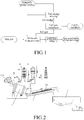
Figure 1 is a flow chart of the process for drying inorganic sludge with a drum according to the present disclosure. -
Figure 2 is a schematic view showing the structure of the apparatus for drying inorganic sludge with a drum according to the present disclosure. - With reference to
Figure 1 , the method of directly drying inorganic sludge by a drum process comprises the following steps: - Slag and sludge are conveyed to a drum with their respective conveying devices at a specific ratio, wherein the slag and the sludge are mixed, heat exchanged, dehydrated, cooled and broken under the action of rotation of the drum and rolling of steel balls, whereby the slag and the sludge are cooled and dried, followed by direct discharge. The inorganic sludge has an initial water content of 70%-99%, and a target water content of 3%-15% after drying. A slag/sludge flow ratio of the slag to the inorganic sludge is 1.5-3.0. The mass of the dryable inorganic sludge is 10t/h-80t/h.
- The steel slag and the dry sludge are separated by a combination of screening and spinning.
- Wet alkaline washing and activated carbon adsorption are utilized to treat dust, sulfides and organic compounds existing in the tail gas generated during the drying of the sludge by the drum process, and then the gas is discharged.
- Steam and dust are generated when the slag and the sludge are treated in the drum. The dust is carried by the steam into a tail gas treatment device where the dust is wet washed or sprinkled, then collected. Then, the dust is conveyed with a conveying device to a tail sludge mixing device where the dust is mixed with primary sludge, agitated, and then regularly, quantitatively conveyed to the drum device with a conveying device such as a sludge pump for drying treatment, thereby achieving zero discharge of undried sludge. The water content of the tail sludge after mixing and agitation should not have an unduly large difference from the water content of the primary sludge, wherein the water content difference should not exceed ±5%.
- Preferably, in step 2), a screening process is used for separating the slag from the sludge, wherein the screen mesh number is not less than 60 meshes.
- With reference to
Figure 2 , the apparatus for directly drying inorganic sludge by a drum process according to the present disclosure comprises: adrum 1 containing a number of steel balls; a slag-sludge conveying device 2 having an inlet end corresponding to an outlet of thedrum 1; a slag-sludge separation device 3 having an inlet end corresponding to an outlet of the slag-sludge conveying device 2 and outlets corresponding to different stock bins; a tail gas treatment device 4 having a gas inlet connected to the outlet of thedrum 1 through a conveying pipeline; a tail sludge mixing device 5 having an inlet connected to a dust mud outlet of the tail gas treatment device 4 through a conveying pipeline, wherein an outlet of the tail sludge mixing device 5 is connected to an inlet of thedrum 1 through a mud conveying pipeline and a sludge pump. - Preferably, the slag-sludge separation device utilizes a screening process, wherein the screen mesh number is not less than 60 meshes.
- The present disclosure employs a hot slag drum treatment process. The molten slag and the inorganic sludge are synchronously conveyed to the drum at a specific ratio with a molten slag conveying device and a sludge conveying system respectively. The slag and the sludge are fully mixed by the rotation of the drum. After the mass and heat transfer process of the slag and sludge, cold granular slag and dried sludge having the required water content are obtained. The apparatus of the present disclosure can realize rapid, steady and low-cost treatment of slag granulation and sludge drying.
- The working process is as follows:
Metallurgical slag 100 is first continuously conveyed to arotating drum 1 from a slag pot. At the same time, inorganic sludge is conveyed to thedrum 1 at a given flow rate with a sludge conveying device from a place where it is produced. Under the combined action of the drum body and steel balls in thedrum 1, the slag and the water-containing sludge are fully mixed. After the heat and mass transfer process, the slag is granulated, and the sludge is dehydrated. Then, thesludge 200 is conveyed with a sealed slag-sludge conveying device 2 to a slag-sludge separation device 3 for treatment. The separated materials enter different stock bins according to the composition and classification. The waste gas generated during the drum drying of the sludge is purified by a tail gas treatment device 4 and discharged when it satisfies the discharge standard. The tail sludge generated in the tail gas treatment device 4 is pumped into an inlet of a tail sludge mixing device 5 with a sludge conveying pump, mixed with the mud generated from a sludge source, agitated uniformly with an agitator, and pumped with a sludge pump at a specified concentration into a mud conveying pipeline through which it is sent to thedrum 1. - According to a comprehensive treatment process for granulating steel slag and drying OG sludge with a drum in a steel mill, a single drum device treated 180,000 tons of high-temperature steel slag per year. In the process of treating the steel slag, OG sludge mud having a water content of 80% was pumped into the drum device. The water in the OG sludge mud was used to cool the high-temperature steel slag, while the sensible heat of the steel slag was used to dry the sludge. The target water content of the sludge was set to 3%. The flow ratio of the slag/sludge fed into the drum was 1.9:1.0. 95,000 tons of OG sludge could be dried every year. After rapid treatment such as drum cooling and dehydration, the slag-sludge (100-130°C) was directly conveyed to a slag-sludge separation device with a conveying device. The sludge was dried to a water content of about 3%. The whole process only took 5 minutes. After full heat exchange in the drum, the steel slag and the dried sludge were continuously discharged from the lower part of the slag-sludge separation device. After screening and even spinning, the granular slag and the sludge powder were sent to different stock bins, waiting for trucks to be delivered to users.
- In the process of treating steel slag, OG sludge mud having a water content of 70% was pumped into a drum device. The water in the OG sludge mud was used to cool the high-temperature steel slag, while the sensible heat of the steel slag was used to dry the sludge. The target water content of the sludge was set to 15%. The flow ratio of the slag/sludge fed into the drum was 1.5:1.0. After rapid treatment such as drum cooling and dehydration, the slag-sludge (100-130°C) was directly conveyed to a slag-sludge separation device with a conveying device. The sludge was dried to a water content of about 3%. The whole process only took 5 minutes. After full heat exchange in the drum, the steel slag and the dried sludge were continuously discharged from the lower part of the slag-sludge separation device. After screening and even spinning, the granular slag and the sludge powder were sent to different stock bins, waiting for trucks to be delivered to users.
- In the process of treating steel slag, OG sludge mud having a water content of 95% was pumped into a drum device. The water in the OG sludge mud was used to cool the high-temperature steel slag, while the sensible heat of the steel slag was used to dry the sludge. The target water content of the sludge was set to 3%. The flow ratio of the slag/sludge fed into the drum was 3.0:1.0. After rapid treatment such as drum cooling and dehydration, the slag-sludge (100-130°C) was directly conveyed to a slag-sludge separation device with a conveying device. The sludge was dried to a water content of about 3%. The whole process only took 5 minutes. After full heat exchange in the drum, the steel slag and the dried sludge were continuously discharged from the lower part of the slag-sludge separation device. After screening and even spinning, the granular slag and the sludge powder were sent to different stock bins, waiting for trucks to be delivered to users.
- In the process of treating steel slag, a batch-wise mode was adopted for feeding, wherein OG sludge mud having a water content of 80% was pumped into a drum device. The water in the OG sludge mud was used to cool the high-temperature steel slag, while the sensible heat of the steel slag was used to dry the sludge. The target water content of the sludge was set to 3%. The mass ratio of the slag/sludge fed into the drum was 1.9:1.0. After rapid treatment such as drum cooling and dehydration, the slag-sludge (100-130°C) was directly conveyed to a slag-sludge separation device with a conveying device. The sludge was dried to a water content of about 3%. The whole process only took 5 minutes. After full heat exchange in the drum, the steel slag and the dried sludge were continuously discharged from the lower part of the slag-sludge separation device. After screening and even spinning, the granular slag and the sludge powder were sent to different stock bins, waiting for trucks to be delivered to users.
Claims (13)
- A method of drying inorganic sludge with molten slag, comprising the following steps: mixing slag and sludge; and separating steel slag and dry sludge after a water content of the sludge is reduced to 3%-15%.
- The method of drying inorganic sludge with molten slag according to claim 1, wherein a mixing mass ratio of the slag to the sludge is 1.5-3.
- The method of drying inorganic sludge with molten slag according to claim 1, wherein the steel slag and the dry sludge are separated by a combination of screening and spinning.
- The method of drying inorganic sludge with molten slag according to claim 1, wherein the method further comprises a tail gas treatment step and a tail sludge treatment step.
- The method of drying inorganic sludge with molten slag according to claim 4, whereinthe tail gas treatment comprises: treating dust, sulfides and organic compounds existing in a tail gas generated during the drying of the sludge by means of wet alkaline washing and/or activated carbon adsorption, and then discharging the tail gas;the tail sludge treatment comprises wet washing or sprinkling the resulting dust, collecting the dust, mixing the dust with sludge to be dried, agitating, and mixing with slag for drying treatment.
- The method of drying inorganic sludge with molten slag according to claim 1, wherein the slag and the sludge are mixed in a drum containing steel balls.
- The method of drying inorganic sludge with molten slag according to claim 6, wherein the method comprises: conveying the slag and the sludge to the drum containing the steel balls with respective conveying devices; and after the water content of the sludge is reduced to 3%-15%, conveying a mixture of the steel slag and the dry sludge to a slag-sludge separation device with a slag-sludge conveying device positioned at an outlet end of the drum to separate the steel slag from the dry sludge, wherein dust, sulfides and organic compounds existing in a tail gas generated during the drying of the sludge enter a tail gas treatment device from a drum outlet, and the gas is discharged when it satisfies the discharge standard after the treatment; wherein the dust separated in the tail gas treatment enters a tail sludge mixing device from a dust mud outlet of the tail gas treatment device, mixes with sludge to be dried, and is then conveyed to the drum through a mud conveying pipeline.
- The method of drying inorganic sludge with molten slag according to claim 3, wherein the slag-sludge separation device utilizes a screening process, wherein a screen mesh number is not less than 60 meshes.
- The method of drying inorganic sludge with molten slag according to claim 1, wherein mixing and drying are carried out in batches, by flow addition or by semi-flow addition.
- A method of directly drying inorganic sludge by a drum process, wherein the method comprises the following steps:1) Mixing sludge with slag in a drum for drying
wherein the slag and the sludge are conveyed to the drum with their respective conveying devices at a specific flow ratio; wherein the slag and the sludge are mixed, heat exchanged, dehydrated, cooled and broken under the action of rotation of the drum and rolling of steel balls, whereby the slag and the sludge are cooled and dried, followed by direct discharge; wherein the inorganic sludge has an initial water content of 70%-99%, and a target water content of 3%-15% after drying; wherein a slag/sludge flow ratio of the slag to the inorganic sludge is 1.5-3.0; wherein the inorganic sludge has a flow rate of 10t/h-80t/h;2) Separating the slag from the sludge
wherein the steel slag and the dry sludge are separated by a combination of screening and spinning;3) Treating tail gas
wherein wet alkaline washing and activated carbon adsorption are utilized to treat dust, sulfides and organic compounds existing in the tail gas generated during the drying of the sludge by the drum process, and then the gas is discharged;4) Treating tail sludge
wherein the dust generated in the tail gas treatment is wet washed or sprinkled, collected, and then conveyed to a tail sludge mixing device with a conveying device, wherein the dust is mixed with primary sludge, agitated, and then regularly conveyed to the drum with a sludge pump for drying treatment, wherein a difference between a water content of the tail sludge after mixing and agitation and the initial water content of the inorganic sludge does not exceed ±5%. - The method of directly drying inorganic sludge by a drum process according to claim 10, wherein in step 2), a screening process is used for separating the slag from the sludge, wherein a screen mesh number is not less than 60 meshes.
- An apparatus for directly drying inorganic sludge by a drum process, comprising:
a drum containing a number of steel balls;a slag-sludge conveying device having an inlet end corresponding to an outlet of the drum;a slag-sludge separation device having an inlet end corresponding to an outlet of the slag-sludge conveying device and outlets corresponding to different stock bins;a tail gas treatment device having a gas inlet connected to the outlet of the drum through a conveying pipeline;a tail sludge mixing device having an inlet connected to a dust mud outlet of the tail gas treatment device through a conveying pipeline;a mud conveying pipeline configured to connect an outlet of the tail sludge mixing device to an inlet of the drum; anda sludge pump arranged on the mud conveying pipeline for pumping the sludge to the drum. - The apparatus for directly drying inorganic sludge by a drum process according to claim 12, wherein the slag-sludge separation device utilizes a screening process, wherein a screen mesh number is not less than 60 meshes.
Applications Claiming Priority (2)
| Application Number | Priority Date | Filing Date | Title |
|---|---|---|---|
| CN201811145994.0A CN109293194B (en) | 2018-09-29 | 2018-09-29 | Method and device for directly drying inorganic sludge by drum method |
| PCT/CN2019/108152 WO2020063745A1 (en) | 2018-09-29 | 2019-09-26 | Method and apparatus for direct drying of inorganic sludge with drum drawing process |
Publications (3)
| Publication Number | Publication Date |
|---|---|
| EP3858792A1 true EP3858792A1 (en) | 2021-08-04 |
| EP3858792A4 EP3858792A4 (en) | 2021-10-06 |
| EP3858792B1 EP3858792B1 (en) | 2024-02-07 |
Family
ID=65165021
Family Applications (1)
| Application Number | Title | Priority Date | Filing Date |
|---|---|---|---|
| EP19866463.3A Active EP3858792B1 (en) | 2018-09-29 | 2019-09-26 | Method and apparatus for direct drying of inorganic sludge with drum drawing process |
Country Status (7)
| Country | Link |
|---|---|
| US (1) | US11891318B2 (en) |
| EP (1) | EP3858792B1 (en) |
| JP (1) | JP7190560B2 (en) |
| KR (1) | KR102928333B1 (en) |
| CN (1) | CN109293194B (en) |
| TW (1) | TWI815980B (en) |
| WO (1) | WO2020063745A1 (en) |
Cited By (1)
| Publication number | Priority date | Publication date | Assignee | Title |
|---|---|---|---|---|
| CN111253045A (en) * | 2020-02-01 | 2020-06-09 | 肇庆泉兴生态科技有限公司 | Steel slag-based town sludge dehydrating agent and dehydrating method thereof |
Families Citing this family (15)
| Publication number | Priority date | Publication date | Assignee | Title |
|---|---|---|---|---|
| CN109293194B (en) | 2018-09-29 | 2022-07-26 | 宝山钢铁股份有限公司 | Method and device for directly drying inorganic sludge by drum method |
| CN114057372B (en) * | 2020-07-31 | 2023-11-14 | 宝山钢铁股份有限公司 | Roller slag waste heat drying method for organic sludge |
| CN114057371B (en) * | 2020-07-31 | 2023-11-14 | 宝山钢铁股份有限公司 | Sludge drying treatment method based on particle heat source |
| CN114058747B (en) * | 2020-07-31 | 2022-12-16 | 宝山钢铁股份有限公司 | Dry-type granulated slag and sludge coupling drying process and device |
| CN112094030B (en) * | 2020-09-17 | 2022-12-13 | 毅康科技有限公司 | Sludge drying and crushing treatment device |
| CN112503856A (en) * | 2020-12-07 | 2021-03-16 | 张绪祎 | Method for drying cold-quenched liquid molten material by using wet mud material |
| CN112408748A (en) * | 2020-12-10 | 2021-02-26 | 天津市融泰水务有限公司 | Rapid sludge granulation drying treatment system and treatment method based on medium loading |
| CN113800731A (en) * | 2021-09-14 | 2021-12-17 | 蕉岭伟态环保有限责任公司 | A kind of urban sludge harmless environmental protection treatment system |
| CN115253400B (en) * | 2022-08-08 | 2023-08-11 | 无锡市曜通环保机械有限公司 | Continuous Cyclone Clarification Treatment Equipment |
| US12054795B2 (en) * | 2022-09-22 | 2024-08-06 | Shandong University | System and method for delivering fluidized powder based on flue gas carrying waste slag and instant cooling steel slag |
| CN116920536B (en) * | 2023-05-11 | 2024-10-11 | 国电环境保护研究院有限公司 | Coal-fired flue gas and desulfurization wastewater treatment equipment |
| CN116481287B (en) * | 2023-06-25 | 2023-08-18 | 德州斯诺威机械有限公司 | Online drying device of pellet feed processing |
| CN118545886B (en) * | 2024-05-28 | 2025-04-01 | 浙江一树纸业集团有限公司 | A papermaking sludge recycling system and process |
| CN119533111B (en) * | 2024-11-27 | 2025-11-04 | 华东理工大学 | A method and apparatus for self-feedback drying of moisture content in all materials. |
| CN120120823B (en) * | 2025-05-12 | 2025-09-02 | 内蒙古民泽农牧科技有限公司 | A raw material drying equipment for organic fertilizer production and processing |
Family Cites Families (26)
| Publication number | Priority date | Publication date | Assignee | Title |
|---|---|---|---|---|
| US3165268A (en) * | 1963-01-08 | 1965-01-12 | Harsco Corp | Method and apparatus for processing ferrous slag |
| US3909410A (en) * | 1973-02-20 | 1975-09-30 | Young W Elmo | Process for treating sewage sludge |
| JPS62294140A (en) * | 1986-06-11 | 1987-12-21 | Nippon Jiryoku Senko Kk | Treatment of slag produced in iron making plant |
| US4787323A (en) | 1987-08-12 | 1988-11-29 | Atlantic Richfield Company | Treating sludges and soil materials contaminated with hydrocarbons |
| JPH0741269B2 (en) * | 1991-08-12 | 1995-05-10 | 日本ケミテック株式会社 | Metal recovery method from sludge |
| TW585924B (en) * | 2002-04-03 | 2004-05-01 | Kobe Steel Ltd | Method for making reduced iron |
| CN1329332C (en) * | 2004-08-31 | 2007-08-01 | 宝山钢铁股份有限公司 | High-viscosity molten slag treating method by drum process |
| RU2293070C2 (en) | 2005-04-18 | 2007-02-10 | Василий Михайлович Кнатько | Method of complex processing and utilization of waste water sediments |
| KR100685385B1 (en) * | 2005-10-26 | 2007-02-22 | 이보엠텍 주식회사 | Waste water sludge recycling equipment |
| CN100523684C (en) | 2007-12-14 | 2009-08-05 | 东南大学 | Enclosed multi-chamber fluidized bed drying method for sludge |
| JP2009233563A (en) | 2008-03-27 | 2009-10-15 | Metawater Co Ltd | Operation control method of sludge dryer |
| CN201327265Y (en) | 2008-08-22 | 2009-10-14 | 北京中矿环保科技股份有限公司 | Sludge drying system, corresponding thermal power plant and sludge generating system |
| CN101885574A (en) * | 2009-05-14 | 2010-11-17 | 武汉东海石化重型装备有限公司 | Outfit for municipal sludge thermal oxidation treatment |
| JP5815209B2 (en) * | 2010-02-09 | 2015-11-17 | 月島機械株式会社 | Method and equipment for drying organic water-containing waste |
| US9016477B2 (en) * | 2012-03-19 | 2015-04-28 | Mid-American Gunite, Inc. | Method and system for processing slag material |
| KR101197299B1 (en) * | 2012-05-08 | 2012-11-05 | (주) 엠엔이엔티 | Apparatus for sorting solid waste |
| RU2545574C2 (en) | 2012-11-16 | 2015-04-10 | Федеральное государственное бюджетное образовательное учреждение высшего профессионального образования "Кемеровский государственный университет" | Method of processing of sewage sludge |
| CN104512988A (en) * | 2013-09-29 | 2015-04-15 | 宝山钢铁股份有限公司 | Method for treating heavy metal sludge by using stainless steel molten slag |
| KR101729994B1 (en) * | 2015-10-28 | 2017-04-25 | 주식회사 한미엔텍 | Low-temperature dry apparatus for sludge using heat transfer media and dry method thereof |
| CN105399304B (en) * | 2015-12-25 | 2017-12-01 | 柳建国 | Biological sludge drying and incineration circulation process method and its complete set of equipments |
| CN105731754A (en) * | 2016-02-24 | 2016-07-06 | 同济大学 | Treatment device and method for drying sludge through slag waste heat |
| CN105948459A (en) * | 2016-05-19 | 2016-09-21 | 山东齐盛机电工程有限公司 | Method using drying and incineration to treat sludge |
| CN107557505A (en) | 2016-06-30 | 2018-01-09 | 宝山钢铁股份有限公司 | Drum method treatment process and treatment device suitable for full steel slag treatment |
| KR101736191B1 (en) * | 2016-09-01 | 2017-05-16 | 주식회사 한미엔텍 | Low-temperature dry apparatus for sludge using self-made granule and dry method thereof |
| RU2666862C1 (en) | 2017-04-20 | 2018-09-12 | ООО "СтройИнвестТопаз" | Method of carrying out mechanically decreased sediments of sewage waters |
| CN109293194B (en) * | 2018-09-29 | 2022-07-26 | 宝山钢铁股份有限公司 | Method and device for directly drying inorganic sludge by drum method |
-
2018
- 2018-09-29 CN CN201811145994.0A patent/CN109293194B/en active Active
-
2019
- 2019-09-26 US US17/278,435 patent/US11891318B2/en active Active
- 2019-09-26 JP JP2021516959A patent/JP7190560B2/en active Active
- 2019-09-26 WO PCT/CN2019/108152 patent/WO2020063745A1/en not_active Ceased
- 2019-09-26 KR KR1020217011900A patent/KR102928333B1/en active Active
- 2019-09-26 EP EP19866463.3A patent/EP3858792B1/en active Active
- 2019-09-27 TW TW108135115A patent/TWI815980B/en active
Cited By (1)
| Publication number | Priority date | Publication date | Assignee | Title |
|---|---|---|---|---|
| CN111253045A (en) * | 2020-02-01 | 2020-06-09 | 肇庆泉兴生态科技有限公司 | Steel slag-based town sludge dehydrating agent and dehydrating method thereof |
Also Published As
| Publication number | Publication date |
|---|---|
| TWI815980B (en) | 2023-09-21 |
| US20210347665A1 (en) | 2021-11-11 |
| CN109293194B (en) | 2022-07-26 |
| EP3858792B1 (en) | 2024-02-07 |
| CN109293194A (en) | 2019-02-01 |
| JP2022501187A (en) | 2022-01-06 |
| KR102928333B1 (en) | 2026-02-19 |
| WO2020063745A1 (en) | 2020-04-02 |
| JP7190560B2 (en) | 2022-12-15 |
| KR20210059774A (en) | 2021-05-25 |
| EP3858792A4 (en) | 2021-10-06 |
| BR112021004122A2 (en) | 2021-05-25 |
| TW202026255A (en) | 2020-07-16 |
| US11891318B2 (en) | 2024-02-06 |
Similar Documents
| Publication | Publication Date | Title |
|---|---|---|
| US11891318B2 (en) | Method and apparatus for direct drying of inorganic sludge with drum drawing process | |
| EP4190919B1 (en) | Integrated drying process and device for dry granulated slag and sludge | |
| WO2013026263A1 (en) | Method for retreating dewatered sludge | |
| CN114956618B (en) | Cement kiln co-treatment fly ash system | |
| CN110330211A (en) | A kind of high-temperature steel slag couples the technique and device of desiccation with sludge | |
| CN206783511U (en) | A sludge deep dehydration, drying, carbonization treatment and disposal system | |
| CN114763262B (en) | Petroleum coke treatment process and petroleum coke treatment system | |
| CN111847409B (en) | Method for producing phosphorite powder ball by utilizing phosphorite powder | |
| CN101497939B (en) | Novel method for producing iron ore pellet binder | |
| CN108455613A (en) | Carbide slag prepares active calcium oxide carbide raw material circulation utilization method and its device | |
| CN110822453B (en) | A pretreatment system and pretreatment method for comprehensive utilization of coal gangue | |
| CN107974522A (en) | The retracting device and method of a kind of blast-furnace cement sensible heat | |
| CN110183122B (en) | System and method for preparing cementing material based on industrial waste heat cooperative disposal of solid waste | |
| CN114057371B (en) | Sludge drying treatment method based on particle heat source | |
| CN111635249A (en) | Lightweight high-strength ceramsite and preparation method thereof | |
| CN112158861A (en) | Production system of low chlorine potassium sulfate | |
| RU2800936C2 (en) | Method for direct dehydration of inorganic sludge by means of a drum-type process and a device for its implementation | |
| CN110835679B (en) | A method for preparing granular spodumene by granulating fine powder spodumene | |
| CN221789068U (en) | A sodium carbonate mixed salt resource disposal device | |
| CN210979879U (en) | Coal gangue comprehensive utilization pretreatment system | |
| BR112021004122B1 (en) | METHOD AND APPARATUS FOR DIRECT DRYING OF INORGANIC SLUDGE WITH DRUM EXTRACTION PROCESS | |
| CN114057372B (en) | Roller slag waste heat drying method for organic sludge | |
| CN210826301U (en) | Comprehensive utilization equipment system for gold smelting slag | |
| CN223268559U (en) | Ceramsite production line | |
| CN218665672U (en) | Sludge innocent treatment system |
Legal Events
| Date | Code | Title | Description |
|---|---|---|---|
| STAA | Information on the status of an ep patent application or granted ep patent |
Free format text: STATUS: THE INTERNATIONAL PUBLICATION HAS BEEN MADE |
|
| PUAI | Public reference made under article 153(3) epc to a published international application that has entered the european phase |
Free format text: ORIGINAL CODE: 0009012 |
|
| STAA | Information on the status of an ep patent application or granted ep patent |
Free format text: STATUS: REQUEST FOR EXAMINATION WAS MADE |
|
| 17P | Request for examination filed |
Effective date: 20210304 |
|
| AK | Designated contracting states |
Kind code of ref document: A1 Designated state(s): AL AT BE BG CH CY CZ DE DK EE ES FI FR GB GR HR HU IE IS IT LI LT LU LV MC MK MT NL NO PL PT RO RS SE SI SK SM TR |
|
| A4 | Supplementary search report drawn up and despatched |
Effective date: 20210908 |
|
| RIC1 | Information provided on ipc code assigned before grant |
Ipc: C02F 103/16 20060101ALN20210902BHEP Ipc: C02F 103/18 20060101ALN20210902BHEP Ipc: B01D 47/06 20060101ALI20210902BHEP Ipc: B01D 53/79 20060101ALI20210902BHEP Ipc: B01D 53/72 20060101ALI20210902BHEP Ipc: B01D 53/52 20060101ALI20210902BHEP Ipc: C21B 3/08 20060101ALI20210902BHEP Ipc: F26B 11/04 20060101ALI20210902BHEP Ipc: C02F 11/13 20190101ALI20210902BHEP Ipc: F26B 3/18 20060101ALI20210902BHEP Ipc: C02F 11/18 20060101ALI20210902BHEP Ipc: C02F 11/12 20190101AFI20210902BHEP |
|
| DAV | Request for validation of the european patent (deleted) | ||
| DAX | Request for extension of the european patent (deleted) | ||
| STAA | Information on the status of an ep patent application or granted ep patent |
Free format text: STATUS: EXAMINATION IS IN PROGRESS |
|
| 17Q | First examination report despatched |
Effective date: 20221007 |
|
| GRAP | Despatch of communication of intention to grant a patent |
Free format text: ORIGINAL CODE: EPIDOSNIGR1 |
|
| STAA | Information on the status of an ep patent application or granted ep patent |
Free format text: STATUS: GRANT OF PATENT IS INTENDED |
|
| RIC1 | Information provided on ipc code assigned before grant |
Ipc: C02F 103/16 20060101ALN20230830BHEP Ipc: C02F 103/18 20060101ALN20230830BHEP Ipc: B01D 53/48 20060101ALI20230830BHEP Ipc: B01D 53/44 20060101ALI20230830BHEP Ipc: F26B 25/00 20060101ALI20230830BHEP Ipc: F26B 3/20 20060101ALI20230830BHEP Ipc: B01D 47/06 20060101ALI20230830BHEP Ipc: B01D 53/79 20060101ALI20230830BHEP Ipc: B01D 53/72 20060101ALI20230830BHEP Ipc: B01D 53/52 20060101ALI20230830BHEP Ipc: C21B 3/08 20060101ALI20230830BHEP Ipc: F26B 11/04 20060101ALI20230830BHEP Ipc: C02F 11/13 20190101ALI20230830BHEP Ipc: F26B 3/18 20060101ALI20230830BHEP Ipc: C02F 11/18 20060101ALI20230830BHEP Ipc: C02F 11/12 20190101AFI20230830BHEP |
|
| INTG | Intention to grant announced |
Effective date: 20230929 |
|
| GRAS | Grant fee paid |
Free format text: ORIGINAL CODE: EPIDOSNIGR3 |
|
| GRAA | (expected) grant |
Free format text: ORIGINAL CODE: 0009210 |
|
| STAA | Information on the status of an ep patent application or granted ep patent |
Free format text: STATUS: THE PATENT HAS BEEN GRANTED |
|
| AK | Designated contracting states |
Kind code of ref document: B1 Designated state(s): AL AT BE BG CH CY CZ DE DK EE ES FI FR GB GR HR HU IE IS IT LI LT LU LV MC MK MT NL NO PL PT RO RS SE SI SK SM TR |
|
| REG | Reference to a national code |
Ref country code: GB Ref legal event code: FG4D |
|
| REG | Reference to a national code |
Ref country code: CH Ref legal event code: EP |
|
| REG | Reference to a national code |
Ref country code: IE Ref legal event code: FG4D |
|
| REG | Reference to a national code |
Ref country code: DE Ref legal event code: R096 Ref document number: 602019046307 Country of ref document: DE |
|
| REG | Reference to a national code |
Ref country code: LT Ref legal event code: MG9D |
|
| REG | Reference to a national code |
Ref country code: NL Ref legal event code: MP Effective date: 20240207 |
|
| PG25 | Lapsed in a contracting state [announced via postgrant information from national office to epo] |
Ref country code: IS Free format text: LAPSE BECAUSE OF FAILURE TO SUBMIT A TRANSLATION OF THE DESCRIPTION OR TO PAY THE FEE WITHIN THE PRESCRIBED TIME-LIMIT Effective date: 20240607 |
|
| PG25 | Lapsed in a contracting state [announced via postgrant information from national office to epo] |
Ref country code: LT Free format text: LAPSE BECAUSE OF FAILURE TO SUBMIT A TRANSLATION OF THE DESCRIPTION OR TO PAY THE FEE WITHIN THE PRESCRIBED TIME-LIMIT Effective date: 20240207 |
|
| PG25 | Lapsed in a contracting state [announced via postgrant information from national office to epo] |
Ref country code: GR Free format text: LAPSE BECAUSE OF FAILURE TO SUBMIT A TRANSLATION OF THE DESCRIPTION OR TO PAY THE FEE WITHIN THE PRESCRIBED TIME-LIMIT Effective date: 20240508 |
|
| REG | Reference to a national code |
Ref country code: AT Ref legal event code: MK05 Ref document number: 1655271 Country of ref document: AT Kind code of ref document: T Effective date: 20240207 |
|
| PG25 | Lapsed in a contracting state [announced via postgrant information from national office to epo] |
Ref country code: HR Free format text: LAPSE BECAUSE OF FAILURE TO SUBMIT A TRANSLATION OF THE DESCRIPTION OR TO PAY THE FEE WITHIN THE PRESCRIBED TIME-LIMIT Effective date: 20240207 Ref country code: RS Free format text: LAPSE BECAUSE OF FAILURE TO SUBMIT A TRANSLATION OF THE DESCRIPTION OR TO PAY THE FEE WITHIN THE PRESCRIBED TIME-LIMIT Effective date: 20240507 Ref country code: NL Free format text: LAPSE BECAUSE OF FAILURE TO SUBMIT A TRANSLATION OF THE DESCRIPTION OR TO PAY THE FEE WITHIN THE PRESCRIBED TIME-LIMIT Effective date: 20240207 |
|
| PG25 | Lapsed in a contracting state [announced via postgrant information from national office to epo] |
Ref country code: ES Free format text: LAPSE BECAUSE OF FAILURE TO SUBMIT A TRANSLATION OF THE DESCRIPTION OR TO PAY THE FEE WITHIN THE PRESCRIBED TIME-LIMIT Effective date: 20240207 |
|
| PG25 | Lapsed in a contracting state [announced via postgrant information from national office to epo] |
Ref country code: AT Free format text: LAPSE BECAUSE OF FAILURE TO SUBMIT A TRANSLATION OF THE DESCRIPTION OR TO PAY THE FEE WITHIN THE PRESCRIBED TIME-LIMIT Effective date: 20240207 |
|
| PG25 | Lapsed in a contracting state [announced via postgrant information from national office to epo] |
Ref country code: RS Free format text: LAPSE BECAUSE OF FAILURE TO SUBMIT A TRANSLATION OF THE DESCRIPTION OR TO PAY THE FEE WITHIN THE PRESCRIBED TIME-LIMIT Effective date: 20240507 Ref country code: NO Free format text: LAPSE BECAUSE OF FAILURE TO SUBMIT A TRANSLATION OF THE DESCRIPTION OR TO PAY THE FEE WITHIN THE PRESCRIBED TIME-LIMIT Effective date: 20240507 Ref country code: NL Free format text: LAPSE BECAUSE OF FAILURE TO SUBMIT A TRANSLATION OF THE DESCRIPTION OR TO PAY THE FEE WITHIN THE PRESCRIBED TIME-LIMIT Effective date: 20240207 Ref country code: LT Free format text: LAPSE BECAUSE OF FAILURE TO SUBMIT A TRANSLATION OF THE DESCRIPTION OR TO PAY THE FEE WITHIN THE PRESCRIBED TIME-LIMIT Effective date: 20240207 Ref country code: IS Free format text: LAPSE BECAUSE OF FAILURE TO SUBMIT A TRANSLATION OF THE DESCRIPTION OR TO PAY THE FEE WITHIN THE PRESCRIBED TIME-LIMIT Effective date: 20240607 Ref country code: HR Free format text: LAPSE BECAUSE OF FAILURE TO SUBMIT A TRANSLATION OF THE DESCRIPTION OR TO PAY THE FEE WITHIN THE PRESCRIBED TIME-LIMIT Effective date: 20240207 Ref country code: GR Free format text: LAPSE BECAUSE OF FAILURE TO SUBMIT A TRANSLATION OF THE DESCRIPTION OR TO PAY THE FEE WITHIN THE PRESCRIBED TIME-LIMIT Effective date: 20240508 Ref country code: FI Free format text: LAPSE BECAUSE OF FAILURE TO SUBMIT A TRANSLATION OF THE DESCRIPTION OR TO PAY THE FEE WITHIN THE PRESCRIBED TIME-LIMIT Effective date: 20240207 Ref country code: ES Free format text: LAPSE BECAUSE OF FAILURE TO SUBMIT A TRANSLATION OF THE DESCRIPTION OR TO PAY THE FEE WITHIN THE PRESCRIBED TIME-LIMIT Effective date: 20240207 Ref country code: BG Free format text: LAPSE BECAUSE OF FAILURE TO SUBMIT A TRANSLATION OF THE DESCRIPTION OR TO PAY THE FEE WITHIN THE PRESCRIBED TIME-LIMIT Effective date: 20240207 Ref country code: AT Free format text: LAPSE BECAUSE OF FAILURE TO SUBMIT A TRANSLATION OF THE DESCRIPTION OR TO PAY THE FEE WITHIN THE PRESCRIBED TIME-LIMIT Effective date: 20240207 |
|
| PG25 | Lapsed in a contracting state [announced via postgrant information from national office to epo] |
Ref country code: PL Free format text: LAPSE BECAUSE OF FAILURE TO SUBMIT A TRANSLATION OF THE DESCRIPTION OR TO PAY THE FEE WITHIN THE PRESCRIBED TIME-LIMIT Effective date: 20240207 Ref country code: PT Free format text: LAPSE BECAUSE OF FAILURE TO SUBMIT A TRANSLATION OF THE DESCRIPTION OR TO PAY THE FEE WITHIN THE PRESCRIBED TIME-LIMIT Effective date: 20240607 |
|
| PG25 | Lapsed in a contracting state [announced via postgrant information from national office to epo] |
Ref country code: SE Free format text: LAPSE BECAUSE OF FAILURE TO SUBMIT A TRANSLATION OF THE DESCRIPTION OR TO PAY THE FEE WITHIN THE PRESCRIBED TIME-LIMIT Effective date: 20240207 Ref country code: PT Free format text: LAPSE BECAUSE OF FAILURE TO SUBMIT A TRANSLATION OF THE DESCRIPTION OR TO PAY THE FEE WITHIN THE PRESCRIBED TIME-LIMIT Effective date: 20240607 Ref country code: PL Free format text: LAPSE BECAUSE OF FAILURE TO SUBMIT A TRANSLATION OF THE DESCRIPTION OR TO PAY THE FEE WITHIN THE PRESCRIBED TIME-LIMIT Effective date: 20240207 Ref country code: LV Free format text: LAPSE BECAUSE OF FAILURE TO SUBMIT A TRANSLATION OF THE DESCRIPTION OR TO PAY THE FEE WITHIN THE PRESCRIBED TIME-LIMIT Effective date: 20240207 |
|
| PG25 | Lapsed in a contracting state [announced via postgrant information from national office to epo] |
Ref country code: DK Free format text: LAPSE BECAUSE OF FAILURE TO SUBMIT A TRANSLATION OF THE DESCRIPTION OR TO PAY THE FEE WITHIN THE PRESCRIBED TIME-LIMIT Effective date: 20240207 |
|
| PG25 | Lapsed in a contracting state [announced via postgrant information from national office to epo] |
Ref country code: SM Free format text: LAPSE BECAUSE OF FAILURE TO SUBMIT A TRANSLATION OF THE DESCRIPTION OR TO PAY THE FEE WITHIN THE PRESCRIBED TIME-LIMIT Effective date: 20240207 |
|
| PG25 | Lapsed in a contracting state [announced via postgrant information from national office to epo] |
Ref country code: CZ Free format text: LAPSE BECAUSE OF FAILURE TO SUBMIT A TRANSLATION OF THE DESCRIPTION OR TO PAY THE FEE WITHIN THE PRESCRIBED TIME-LIMIT Effective date: 20240207 Ref country code: EE Free format text: LAPSE BECAUSE OF FAILURE TO SUBMIT A TRANSLATION OF THE DESCRIPTION OR TO PAY THE FEE WITHIN THE PRESCRIBED TIME-LIMIT Effective date: 20240207 |
|
| PG25 | Lapsed in a contracting state [announced via postgrant information from national office to epo] |
Ref country code: SK Free format text: LAPSE BECAUSE OF FAILURE TO SUBMIT A TRANSLATION OF THE DESCRIPTION OR TO PAY THE FEE WITHIN THE PRESCRIBED TIME-LIMIT Effective date: 20240207 |
|
| PG25 | Lapsed in a contracting state [announced via postgrant information from national office to epo] |
Ref country code: SM Free format text: LAPSE BECAUSE OF FAILURE TO SUBMIT A TRANSLATION OF THE DESCRIPTION OR TO PAY THE FEE WITHIN THE PRESCRIBED TIME-LIMIT Effective date: 20240207 Ref country code: SK Free format text: LAPSE BECAUSE OF FAILURE TO SUBMIT A TRANSLATION OF THE DESCRIPTION OR TO PAY THE FEE WITHIN THE PRESCRIBED TIME-LIMIT Effective date: 20240207 Ref country code: RO Free format text: LAPSE BECAUSE OF FAILURE TO SUBMIT A TRANSLATION OF THE DESCRIPTION OR TO PAY THE FEE WITHIN THE PRESCRIBED TIME-LIMIT Effective date: 20240207 Ref country code: EE Free format text: LAPSE BECAUSE OF FAILURE TO SUBMIT A TRANSLATION OF THE DESCRIPTION OR TO PAY THE FEE WITHIN THE PRESCRIBED TIME-LIMIT Effective date: 20240207 Ref country code: DK Free format text: LAPSE BECAUSE OF FAILURE TO SUBMIT A TRANSLATION OF THE DESCRIPTION OR TO PAY THE FEE WITHIN THE PRESCRIBED TIME-LIMIT Effective date: 20240207 Ref country code: CZ Free format text: LAPSE BECAUSE OF FAILURE TO SUBMIT A TRANSLATION OF THE DESCRIPTION OR TO PAY THE FEE WITHIN THE PRESCRIBED TIME-LIMIT Effective date: 20240207 |
|
| REG | Reference to a national code |
Ref country code: DE Ref legal event code: R097 Ref document number: 602019046307 Country of ref document: DE |
|
| PG25 | Lapsed in a contracting state [announced via postgrant information from national office to epo] |
Ref country code: IT Free format text: LAPSE BECAUSE OF FAILURE TO SUBMIT A TRANSLATION OF THE DESCRIPTION OR TO PAY THE FEE WITHIN THE PRESCRIBED TIME-LIMIT Effective date: 20240207 |
|
| PLBE | No opposition filed within time limit |
Free format text: ORIGINAL CODE: 0009261 |
|
| STAA | Information on the status of an ep patent application or granted ep patent |
Free format text: STATUS: NO OPPOSITION FILED WITHIN TIME LIMIT |
|
| PG25 | Lapsed in a contracting state [announced via postgrant information from national office to epo] |
Ref country code: IT Free format text: LAPSE BECAUSE OF FAILURE TO SUBMIT A TRANSLATION OF THE DESCRIPTION OR TO PAY THE FEE WITHIN THE PRESCRIBED TIME-LIMIT Effective date: 20240207 |
|
| 26N | No opposition filed |
Effective date: 20241108 |
|
| REG | Reference to a national code |
Ref country code: DE Ref legal event code: R119 Ref document number: 602019046307 Country of ref document: DE |
|
| PG25 | Lapsed in a contracting state [announced via postgrant information from national office to epo] |
Ref country code: SI Free format text: LAPSE BECAUSE OF FAILURE TO SUBMIT A TRANSLATION OF THE DESCRIPTION OR TO PAY THE FEE WITHIN THE PRESCRIBED TIME-LIMIT Effective date: 20240207 Ref country code: MC Free format text: LAPSE BECAUSE OF FAILURE TO SUBMIT A TRANSLATION OF THE DESCRIPTION OR TO PAY THE FEE WITHIN THE PRESCRIBED TIME-LIMIT Effective date: 20240207 |
|
| REG | Reference to a national code |
Ref country code: CH Ref legal event code: PL |
|
| PG25 | Lapsed in a contracting state [announced via postgrant information from national office to epo] |
Ref country code: LU Free format text: LAPSE BECAUSE OF NON-PAYMENT OF DUE FEES Effective date: 20240926 |
|
| PG25 | Lapsed in a contracting state [announced via postgrant information from national office to epo] |
Ref country code: DE Free format text: LAPSE BECAUSE OF NON-PAYMENT OF DUE FEES Effective date: 20250401 |
|
| REG | Reference to a national code |
Ref country code: BE Ref legal event code: MM Effective date: 20240930 |
|
| PG25 | Lapsed in a contracting state [announced via postgrant information from national office to epo] |
Ref country code: BE Free format text: LAPSE BECAUSE OF NON-PAYMENT OF DUE FEES Effective date: 20240930 |
|
| PG25 | Lapsed in a contracting state [announced via postgrant information from national office to epo] |
Ref country code: FR Free format text: LAPSE BECAUSE OF NON-PAYMENT OF DUE FEES Effective date: 20240930 |
|
| PG25 | Lapsed in a contracting state [announced via postgrant information from national office to epo] |
Ref country code: CH Free format text: LAPSE BECAUSE OF NON-PAYMENT OF DUE FEES Effective date: 20240930 |
|
| PG25 | Lapsed in a contracting state [announced via postgrant information from national office to epo] |
Ref country code: IE Free format text: LAPSE BECAUSE OF NON-PAYMENT OF DUE FEES Effective date: 20240926 |
|
| PGFP | Annual fee paid to national office [announced via postgrant information from national office to epo] |
Ref country code: TR Payment date: 20250908 Year of fee payment: 7 |
|
| PGFP | Annual fee paid to national office [announced via postgrant information from national office to epo] |
Ref country code: GB Payment date: 20250905 Year of fee payment: 7 |
|
| PG25 | Lapsed in a contracting state [announced via postgrant information from national office to epo] |
Ref country code: CY Free format text: LAPSE BECAUSE OF FAILURE TO SUBMIT A TRANSLATION OF THE DESCRIPTION OR TO PAY THE FEE WITHIN THE PRESCRIBED TIME-LIMIT; INVALID AB INITIO Effective date: 20190926 |
|
| PG25 | Lapsed in a contracting state [announced via postgrant information from national office to epo] |
Ref country code: HU Free format text: LAPSE BECAUSE OF FAILURE TO SUBMIT A TRANSLATION OF THE DESCRIPTION OR TO PAY THE FEE WITHIN THE PRESCRIBED TIME-LIMIT; INVALID AB INITIO Effective date: 20190926 |