EP3858728A1 - Panel actuation assembly - Google Patents
Panel actuation assembly Download PDFInfo
- Publication number
- EP3858728A1 EP3858728A1 EP20275022.0A EP20275022A EP3858728A1 EP 3858728 A1 EP3858728 A1 EP 3858728A1 EP 20275022 A EP20275022 A EP 20275022A EP 3858728 A1 EP3858728 A1 EP 3858728A1
- Authority
- EP
- European Patent Office
- Prior art keywords
- actuator
- panel
- lifting
- lifting mechanisms
- engagement
- Prior art date
- Legal status (The legal status is an assumption and is not a legal conclusion. Google has not performed a legal analysis and makes no representation as to the accuracy of the status listed.)
- Granted
Links
Images


Classifications
-
- B—PERFORMING OPERATIONS; TRANSPORTING
- B64—AIRCRAFT; AVIATION; COSMONAUTICS
- B64C—AEROPLANES; HELICOPTERS
- B64C13/00—Control systems or transmitting systems for actuating flying-control surfaces, lift-increasing flaps, air brakes, or spoilers
- B64C13/24—Transmitting means
- B64C13/26—Transmitting means without power amplification or where power amplification is irrelevant
- B64C13/28—Transmitting means without power amplification or where power amplification is irrelevant mechanical
- B64C13/34—Transmitting means without power amplification or where power amplification is irrelevant mechanical using toothed gearing
-
- B—PERFORMING OPERATIONS; TRANSPORTING
- B64—AIRCRAFT; AVIATION; COSMONAUTICS
- B64C—AEROPLANES; HELICOPTERS
- B64C13/00—Control systems or transmitting systems for actuating flying-control surfaces, lift-increasing flaps, air brakes, or spoilers
-
- B—PERFORMING OPERATIONS; TRANSPORTING
- B64—AIRCRAFT; AVIATION; COSMONAUTICS
- B64C—AEROPLANES; HELICOPTERS
- B64C3/00—Wings
- B64C3/28—Leading or trailing edges attached to primary structures, e.g. forming fixed slots
-
- B—PERFORMING OPERATIONS; TRANSPORTING
- B64—AIRCRAFT; AVIATION; COSMONAUTICS
- B64C—AEROPLANES; HELICOPTERS
- B64C3/00—Wings
- B64C3/38—Adjustment of complete wings or parts thereof
-
- B—PERFORMING OPERATIONS; TRANSPORTING
- B64—AIRCRAFT; AVIATION; COSMONAUTICS
- B64C—AEROPLANES; HELICOPTERS
- B64C9/00—Adjustable control surfaces or members, e.g. rudders
- B64C9/14—Adjustable control surfaces or members, e.g. rudders forming slots
- B64C9/16—Adjustable control surfaces or members, e.g. rudders forming slots at the rear of the wing
-
- B—PERFORMING OPERATIONS; TRANSPORTING
- B64—AIRCRAFT; AVIATION; COSMONAUTICS
- B64C—AEROPLANES; HELICOPTERS
- B64C9/00—Adjustable control surfaces or members, e.g. rudders
- B64C9/14—Adjustable control surfaces or members, e.g. rudders forming slots
- B64C9/22—Adjustable control surfaces or members, e.g. rudders forming slots at the front of the wing
Definitions
- the present disclosure is concerned with an actuation system for moveable panels in an aircraft.
- Aircraft contain many moveable parts including moveable surfaces such as slats, flaps and other panels that are moved to different positions by means of actuators responding to control commands. Movement of these surfaces affects the flight of the aircraft.
- Tubes generally connect actuators to the moving parts and gearing is provided at the actuators to step down the power.
- actuators to move moveable parts on an aircraft
- high lift slat panels provide on the leading edge of the aircraft wings to control lift of the aircraft, or flap panels on the trailing edge of an aircraft wing.
- the actuators raise and lower these panels as commanded.
- several panels will be provided along the length of the wing and each panel will have two actuators to control its lifting/lowering movement.
- the actuators used in such systems are complex and expensive to manufacture. There is, therefore, a desire to reduce the overall number of actuators without adversely affecting performance and safety.
- an actuator system for controlling movement of a plurality of panels, comprising two or more lifting mechanisms connected to each panel at two or more separate locations on the panel, an actuator in engagement with a first of the lifting mechanisms to drive the lifting mechanism to move the panel, and a torque tube having a first end in engagement with the actuator so as to be rotated by the actuator as the actuator drives the lifting mechanism, the torque tube having a second end in engagement with the or another of the two or more lifting mechanisms to drive the lifting mechanism due to rotation of the torque tube.
- the lifting mechanisms each preferably comprise a rack and pinion arrangement with a rack attached to the panel and the pinion driven by the actuator, and wherein the pinion of the first lifting mechanism is in engagement with the actuator and the pinion of the other lifting mechanism is engaged by the second end of the torque tube.
- the torque tube is preferably a carbon fiber tube.
- more than two lifting mechanisms are provided at respective separate locations on the panel; the actuator may be in engagement with a first of the lifting mechanisms and to drive the other lifting mechanisms via respective torque tubes.
- an aircraft wing comprising a plurality of panels along a leading edge and an actuator system as described above.
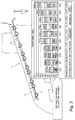
- Fig. 2 shows a typical leading edge 1 having five moveable panels 2.
- the movement of each panel is caused by two geared actuators 3 at two stations spaced apart on the panel - i.e. two actuators are provided per panel - one actuator at or close to each end of the panel.
- the actuators are controlled by a power control unit (PCU) which provides output control signals to the actuators according to a command e.g. from the pilot or flight control system which determines how much and in what direction the panels are moved by the actuators.
- PCU power control unit
- Fig. 1 shows in more detail the structure of a typical actuator having an input shaft 20 which rotates responsive to the command and causes a stepped-down rotation of an output shaft 30 via a gear mechanism.
- the gear mechanism comprises an earth ring gear 40, pinion gears 50 and an output ring gear 60. Seals 70,80 prevent leakage of hydraulic fluid and lubricant.
- Support rings 90 may be provided to support rotation of the actuator components.
- a torque limiter 100 is provided to limit torque from the input shaft.
- the torque limiter is provided in a housing 110 and the gearing is provided in an actuator housing 120.
- a vent 130 may also be provided.
- Such actuator structures are known and will not be described further. Other known actuator structures may also be used.
- the panels 2 are deployed using a known rack and pinion arrangement on a curved track.
- a pinion is provided at each actuator station or location on the panel.
- the actuators are controlled, by the PCU, to move the pinion to cause the desired panel movement.
- a system having only a single actuator per panel.
- a torque tube is provided between the pinions at the two panel stations, that drive the racks to move the panels.
- the sole actuator is provided as usual at the first station and drives the pinion at that station.
- the other pinion is driven by rotation of a high torque tube, e.g. a carbon fiber tube, that is attached to and rotated by the actuator.
- the system can be seen in Fig. 3 showing two stations 200,210 of a moveable panel (not shown in Fig. 3 ) on an aircraft wing.
- a drive mechanism 300,310 is provided to move the panel responsive to the actuator 200,210.
- the drive mechanism here is a typical rack and pinion arrangement by other mechanisms are feasible.
- An actuator 400 is provided at the first station 200 and drives the drive mechanism.
- a torque tube 500 connects the actuator at the first station to the drive mechanism at the second station 210 in torque transmitting connection.
- the torque tube 500 will rotate at the output speed of the actuator 400 to move the pinion at the second station in the same way as the first pinion at the first station is moved by the actuator 400.
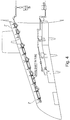
- Fig. 4 shows how the system of this disclosure results in a reduced number of actuators per wing.
- the wing has 5 panels 2'.
- the system of this disclosure is thus much less expensive and easier to manufacture and industrialise than conventional systems.
- the smaller structure of the tube compared to another actuator also means that the wing has less drag and less inertia than when two actuators are present.
Landscapes
- Engineering & Computer Science (AREA)
- Aviation & Aerospace Engineering (AREA)
- Mechanical Engineering (AREA)
- Automation & Control Theory (AREA)
- Transmission Devices (AREA)
- Actuator (AREA)
Abstract
Description
- The present disclosure is concerned with an actuation system for moveable panels in an aircraft.
- Aircraft contain many moveable parts including moveable surfaces such as slats, flaps and other panels that are moved to different positions by means of actuators responding to control commands. Movement of these surfaces affects the flight of the aircraft.
- Tubes generally connect actuators to the moving parts and gearing is provided at the actuators to step down the power.
- One example of the use of actuators to move moveable parts on an aircraft is the high lift slat panels provide on the leading edge of the aircraft wings to control lift of the aircraft, or flap panels on the trailing edge of an aircraft wing. The actuators raise and lower these panels as commanded. Typically, several panels will be provided along the length of the wing and each panel will have two actuators to control its lifting/lowering movement.
- It is also typical to use different strength actuators along the length of the wing as the loads on the panels due to aerodynamics are different.
- The actuators used in such systems are complex and expensive to manufacture. There is, therefore, a desire to reduce the overall number of actuators without adversely affecting performance and safety.
- According to the present disclosure, there is provided an actuator system for controlling movement of a plurality of panels, comprising two or more lifting mechanisms connected to each panel at two or more separate locations on the panel, an actuator in engagement with a first of the lifting mechanisms to drive the lifting mechanism to move the panel, and a torque tube having a first end in engagement with the actuator so as to be rotated by the actuator as the actuator drives the lifting mechanism, the torque tube having a second end in engagement with the or another of the two or more lifting mechanisms to drive the lifting mechanism due to rotation of the torque tube.
- The lifting mechanisms each preferably comprise a rack and pinion arrangement with a rack attached to the panel and the pinion driven by the actuator, and wherein the pinion of the first lifting mechanism is in engagement with the actuator and the pinion of the other lifting mechanism is engaged by the second end of the torque tube.
- The torque tube is preferably a carbon fiber tube.
- In some embodiments, more than two lifting mechanisms are provided at respective separate locations on the panel; the actuator may be in engagement with a first of the lifting mechanisms and to drive the other lifting mechanisms via respective torque tubes.
- In another aspect, there is provided an aircraft wing comprising a plurality of panels along a leading edge and an actuator system as described above.
-
-
Figure 1 is a sectional view of a typical actuator for causing movement of a moveable panel on an aircraft. -
Figure 2 shows a typical arrangement of panels and actuators on the leading edge of an aircraft together with a chart showing example loads. -
Figure 3 is a perspective view of part of a system according to the present disclosure. -
Figure 4 shows an arrangement of panels and actuators on the leading edge of an aircraft according to this disclosure. - The described embodiments are by way of example only. The scope of this disclosure is limited only by the claims.
- Existing actuator systems will first be described with reference to
Figs. 1 and2 . The description relates to the slat panels on the leading edge of the aircraft wing but this is just one example and the same or similar principles apply to other moveable panels. -
Fig. 2 shows a typical leading edge 1 having fivemoveable panels 2. The movement of each panel is caused by two gearedactuators 3 at two stations spaced apart on the panel - i.e. two actuators are provided per panel - one actuator at or close to each end of the panel. The actuators are controlled by a power control unit (PCU) which provides output control signals to the actuators according to a command e.g. from the pilot or flight control system which determines how much and in what direction the panels are moved by the actuators. - As can be seen in the chart the more inboard panels are subjected to a higher load than the more outboard panels and so the output requirements of the actuators vary.
-
Fig. 1 shows in more detail the structure of a typical actuator having aninput shaft 20 which rotates responsive to the command and causes a stepped-down rotation of anoutput shaft 30 via a gear mechanism. In the example shown, the gear mechanism comprises anearth ring gear 40,pinion gears 50 and anoutput ring gear 60.Seals Support rings 90 may be provided to support rotation of the actuator components. Atorque limiter 100 is provided to limit torque from the input shaft. The torque limiter is provided in a housing 110 and the gearing is provided in anactuator housing 120. Avent 130 may also be provided. Such actuator structures are known and will not be described further. Other known actuator structures may also be used. - In a typical system, the
panels 2 are deployed using a known rack and pinion arrangement on a curved track. A pinion is provided at each actuator station or location on the panel. The actuators are controlled, by the PCU, to move the pinion to cause the desired panel movement. - As mentioned above, the actuators used in such systems are expensive and complex.
- According to the present disclosure, a system is provided having only a single actuator per panel. A torque tube is provided between the pinions at the two panel stations, that drive the racks to move the panels. The sole actuator is provided as usual at the first station and drives the pinion at that station. The other pinion is driven by rotation of a high torque tube, e.g. a carbon fiber tube, that is attached to and rotated by the actuator.
- While any high torque material could be used for the tube to achieve advantages in cost savings due to fewer actuators, advancements in carbon fiber tube technology mean that such tubes can be manufactured more easily and at lower cost.
- The system can be seen in
Fig. 3 showing two stations 200,210 of a moveable panel (not shown inFig. 3 ) on an aircraft wing. At each station a drive mechanism 300,310 is provided to move the panel responsive to the actuator 200,210. The drive mechanism here is a typical rack and pinion arrangement by other mechanisms are feasible. - An
actuator 400 is provided at thefirst station 200 and drives the drive mechanism. Atorque tube 500 connects the actuator at the first station to the drive mechanism at thesecond station 210 in torque transmitting connection. - The
torque tube 500 will rotate at the output speed of theactuator 400 to move the pinion at the second station in the same way as the first pinion at the first station is moved by theactuator 400. -
Fig. 4 shows how the system of this disclosure results in a reduced number of actuators per wing. Here, the wing has 5 panels 2'. Theinnermost panel 2" which has the greatest loading, still has two actuators, but the other panels all have only one actuator each with a torque tube connecting the actuator to a second station of the respective panel. - The system of this disclosure is thus much less expensive and easier to manufacture and industrialise than conventional systems. The smaller structure of the tube compared to another actuator also means that the wing has less drag and less inertia than when two actuators are present.
Claims (12)
- An actuator system for controlling movement of a plurality of panels, comprising two or more lifting mechanisms connected to each panel at two or more separate locations on the panel, and, for each panel: an actuator in engagement with a first of the lifting mechanisms to drive the lifting mechanism to move the panel, and a torque tube having a first end in engagement with the actuator so as to be rotated by the actuator as the actuator drives the lifting mechanism, the torque tube having a second end in engagement with the or another of the two or more lifting mechanisms to drive the lifting mechanism due to rotation of the torque tube.
- An actuator system as claimed in claim 1, wherein the lifting mechanisms each comprise a rack and pinion arrangement with a rack attached to the panel and the pinion driven by the actuator, and wherein the pinion of the first lifting mechanism is in engagement with the actuator and the pinion of the other lifting mechanism is engaged by the second end of the torque tube.
- An actuator system as claimed in claim 1 or 2, wherein torque tube is a carbon fiber tube.
- An actuator system as claimed in any preceding claim wherein the actuator of each panel is a geared actuator comprising an input shaft and an output shaft connected by a gear mechanism.
- An actuator system as claimed in any preceding claim, further comprising a control unit to provide a control signal to the actuators.
- An actuator system as claimed in claim 5, wherein the control unit provides the control signal in response to a command from a pilot or a flight control system.
- An actuator system as claimed in any preceding claim, wherein more than two lifting mechanisms are provided at respective separate locations on the panel; the actuator may be in engagement with a first of the lifting mechanisms and to drive the other lifting mechanisms via respective torque tubes.
- An actuator system as claimed in in claim 7, comprising three lifting mechanisms at three separate locations on the panel, wherein the actuator is an engagement with the first lifting mechanism, and comprising a first torque tube connecting the actuator to a second of the lifting mechanisms and a second torque tube connecting the actuator to a third of the lifting mechanisms.
- An aircraft wing comprising a plurality of panels along a leading edge and an actuator system as described above.
- An aircraft wing comprising a plurality of panels along a trailing edge and an actuator system as claimed in any of claims 1 to 6.
- An aircraft having two aircraft wings as claimed in claim 9 or 10.
- A method of controlling movement of a moveable panel of an aircraft wing comprising driving movement of a first lift mechanism of the panel by means of an actuator connected to the first lifting mechanism and moving the panel at a second lifting mechanism of the panel, remote from the first, by means of torque transmitted from the actuator to the first station via a torque transmission tube without an actuator at the second lift mechanism.
Priority Applications (2)
| Application Number | Priority Date | Filing Date | Title |
|---|---|---|---|
| EP20275022.0A EP3858728B1 (en) | 2020-01-31 | 2020-01-31 | Panel actuation assembly |
| US17/162,172 US11858616B2 (en) | 2020-01-31 | 2021-01-29 | Panel actuation assembly |
Applications Claiming Priority (1)
| Application Number | Priority Date | Filing Date | Title |
|---|---|---|---|
| EP20275022.0A EP3858728B1 (en) | 2020-01-31 | 2020-01-31 | Panel actuation assembly |
Publications (2)
| Publication Number | Publication Date |
|---|---|
| EP3858728A1 true EP3858728A1 (en) | 2021-08-04 |
| EP3858728B1 EP3858728B1 (en) | 2024-05-01 |
Family
ID=69500691
Family Applications (1)
| Application Number | Title | Priority Date | Filing Date |
|---|---|---|---|
| EP20275022.0A Active EP3858728B1 (en) | 2020-01-31 | 2020-01-31 | Panel actuation assembly |
Country Status (2)
| Country | Link |
|---|---|
| US (1) | US11858616B2 (en) |
| EP (1) | EP3858728B1 (en) |
Citations (5)
| Publication number | Priority date | Publication date | Assignee | Title |
|---|---|---|---|---|
| GB2390344A (en) * | 2002-07-04 | 2004-01-07 | Smiths Wolverhampton Ltd | Flight surface actuator |
| EP2202146A2 (en) * | 2008-12-23 | 2010-06-30 | Goodrich Actuation Systems Ltd. | Drive arrangement |
| DE102010047540A1 (en) * | 2010-10-05 | 2012-04-05 | Airbus Operations Gmbh | High-lift system for a wing of an aircraft |
| DE102014019134A1 (en) * | 2014-12-18 | 2016-06-23 | Liebherr-Aerospace Lindenberg Gmbh | Buoyancy device for an aircraft with at least one movable flap |
| US9771141B2 (en) * | 2013-09-24 | 2017-09-26 | The Boeing Company | Leading edge system and method for approach noise reduction |
Family Cites Families (6)
| Publication number | Priority date | Publication date | Assignee | Title |
|---|---|---|---|---|
| US4471928A (en) * | 1980-08-13 | 1984-09-18 | The Boeing Company | Extendible airfoil track assembly |
| US6467733B1 (en) * | 2001-11-28 | 2002-10-22 | Northrop Grumman Corporation | Aerodynamic control surface system |
| US6802475B2 (en) * | 2002-07-04 | 2004-10-12 | Smiths Wolverhampton Limited | Flight surface actuator |
| GB0805599D0 (en) * | 2008-03-28 | 2008-04-30 | Airbus Uk Ltd | Slat deployment mechanism |
| EP3505451A1 (en) * | 2017-12-29 | 2019-07-03 | Airbus Operations GmbH | Flight control surface assembly |
| US11060566B2 (en) * | 2018-01-19 | 2021-07-13 | The Boeing Company | Apparatus and methods for rigging a torque tube assembly in an aircraft |
-
2020
- 2020-01-31 EP EP20275022.0A patent/EP3858728B1/en active Active
-
2021
- 2021-01-29 US US17/162,172 patent/US11858616B2/en active Active
Patent Citations (5)
| Publication number | Priority date | Publication date | Assignee | Title |
|---|---|---|---|---|
| GB2390344A (en) * | 2002-07-04 | 2004-01-07 | Smiths Wolverhampton Ltd | Flight surface actuator |
| EP2202146A2 (en) * | 2008-12-23 | 2010-06-30 | Goodrich Actuation Systems Ltd. | Drive arrangement |
| DE102010047540A1 (en) * | 2010-10-05 | 2012-04-05 | Airbus Operations Gmbh | High-lift system for a wing of an aircraft |
| US9771141B2 (en) * | 2013-09-24 | 2017-09-26 | The Boeing Company | Leading edge system and method for approach noise reduction |
| DE102014019134A1 (en) * | 2014-12-18 | 2016-06-23 | Liebherr-Aerospace Lindenberg Gmbh | Buoyancy device for an aircraft with at least one movable flap |
Also Published As
| Publication number | Publication date |
|---|---|
| US20210237854A1 (en) | 2021-08-05 |
| US11858616B2 (en) | 2024-01-02 |
| EP3858728B1 (en) | 2024-05-01 |
Similar Documents
| Publication | Publication Date | Title |
|---|---|---|
| EP1786667B2 (en) | Systems and methods for providing differential motion to wing high lift devices | |
| US12179907B1 (en) | Electrically driven blade control for rotorcraft | |
| US6030177A (en) | Drive system for a variable diameter tilt rotor | |
| US6019578A (en) | Variable diameter rotor blade actuation system | |
| US10946954B2 (en) | Variable-speed drive system for tiltrotor with fixed engine and rotating proprotor | |
| US10538310B2 (en) | Near synchronous distributed hydraulic motor driven actuation system | |
| US10527142B2 (en) | Hydraulic rotary ball screw actuator | |
| EP3431391B1 (en) | Aerodynamic control surface operating system for aircraft using variable transmission | |
| US8376818B2 (en) | Thrust recovery, or other valve, containing two independently actuated doors and control system | |
| EP4039586B1 (en) | Actuator assembly | |
| EP2851289B1 (en) | Leading and trailing edge device deflections during descent of an aircraft | |
| CA2602667C (en) | Landing flap drive system | |
| EP3613666B1 (en) | Actuator system | |
| EP3858728B1 (en) | Panel actuation assembly | |
| US20200079498A1 (en) | Easy-to-mount actuator | |
| EP4549315B1 (en) | Fault tolerant rotary ema | |
| EP3495688B1 (en) | Gearbox split torque equalization system | |
| US11939042B2 (en) | Control surface actuation synchronization system | |
| EP4079631B1 (en) | Rotary actuation for thin wing applications | |
| CN210681150U (en) | A displacement actuating mechanism for unmanned aerial vehicle | |
| US10766602B2 (en) | Mechanical droop for spoiler operation | |
| US12612154B2 (en) | Mechanical architecture for distributed flap actuation system | |
| US20250129843A1 (en) | Rotary ema | |
| KR100243372B1 (en) | Trimming apparatus for use in airplane | |
| Paget | Mechanical Aspects of Variable Sweep Wings |
Legal Events
| Date | Code | Title | Description |
|---|---|---|---|
| PUAI | Public reference made under article 153(3) epc to a published international application that has entered the european phase |
Free format text: ORIGINAL CODE: 0009012 |
|
| STAA | Information on the status of an ep patent application or granted ep patent |
Free format text: STATUS: THE APPLICATION HAS BEEN PUBLISHED |
|
| AK | Designated contracting states |
Kind code of ref document: A1 Designated state(s): AL AT BE BG CH CY CZ DE DK EE ES FI FR GB GR HR HU IE IS IT LI LT LU LV MC MK MT NL NO PL PT RO RS SE SI SK SM TR |
|
| STAA | Information on the status of an ep patent application or granted ep patent |
Free format text: STATUS: REQUEST FOR EXAMINATION WAS MADE |
|
| 17P | Request for examination filed |
Effective date: 20220204 |
|
| RBV | Designated contracting states (corrected) |
Designated state(s): AL AT BE BG CH CY CZ DE DK EE ES FI FR GB GR HR HU IE IS IT LI LT LU LV MC MK MT NL NO PL PT RO RS SE SI SK SM TR |
|
| STAA | Information on the status of an ep patent application or granted ep patent |
Free format text: STATUS: EXAMINATION IS IN PROGRESS |
|
| 17Q | First examination report despatched |
Effective date: 20221122 |
|
| GRAP | Despatch of communication of intention to grant a patent |
Free format text: ORIGINAL CODE: EPIDOSNIGR1 |
|
| STAA | Information on the status of an ep patent application or granted ep patent |
Free format text: STATUS: GRANT OF PATENT IS INTENDED |
|
| INTG | Intention to grant announced |
Effective date: 20231220 |
|
| GRAS | Grant fee paid |
Free format text: ORIGINAL CODE: EPIDOSNIGR3 |
|
| GRAA | (expected) grant |
Free format text: ORIGINAL CODE: 0009210 |
|
| STAA | Information on the status of an ep patent application or granted ep patent |
Free format text: STATUS: THE PATENT HAS BEEN GRANTED |
|
| AK | Designated contracting states |
Kind code of ref document: B1 Designated state(s): AL AT BE BG CH CY CZ DE DK EE ES FI FR GB GR HR HU IE IS IT LI LT LU LV MC MK MT NL NO PL PT RO RS SE SI SK SM TR |
|
| REG | Reference to a national code |
Ref country code: GB Ref legal event code: FG4D |
|
| REG | Reference to a national code |
Ref country code: CH Ref legal event code: EP |
|
| REG | Reference to a national code |
Ref country code: IE Ref legal event code: FG4D |
|
| REG | Reference to a national code |
Ref country code: DE Ref legal event code: R096 Ref document number: 602020030044 Country of ref document: DE |
|
| REG | Reference to a national code |
Ref country code: LT Ref legal event code: MG9D |
|
| REG | Reference to a national code |
Ref country code: NL Ref legal event code: MP Effective date: 20240501 |
|
| PG25 | Lapsed in a contracting state [announced via postgrant information from national office to epo] |
Ref country code: IS Free format text: LAPSE BECAUSE OF FAILURE TO SUBMIT A TRANSLATION OF THE DESCRIPTION OR TO PAY THE FEE WITHIN THE PRESCRIBED TIME-LIMIT Effective date: 20240901 |
|
| PG25 | Lapsed in a contracting state [announced via postgrant information from national office to epo] |
Ref country code: BG Free format text: LAPSE BECAUSE OF FAILURE TO SUBMIT A TRANSLATION OF THE DESCRIPTION OR TO PAY THE FEE WITHIN THE PRESCRIBED TIME-LIMIT Effective date: 20240501 |
|
| PG25 | Lapsed in a contracting state [announced via postgrant information from national office to epo] |
Ref country code: FI Free format text: LAPSE BECAUSE OF FAILURE TO SUBMIT A TRANSLATION OF THE DESCRIPTION OR TO PAY THE FEE WITHIN THE PRESCRIBED TIME-LIMIT Effective date: 20240501 Ref country code: HR Free format text: LAPSE BECAUSE OF FAILURE TO SUBMIT A TRANSLATION OF THE DESCRIPTION OR TO PAY THE FEE WITHIN THE PRESCRIBED TIME-LIMIT Effective date: 20240501 |
|
| PG25 | Lapsed in a contracting state [announced via postgrant information from national office to epo] |
Ref country code: GR Free format text: LAPSE BECAUSE OF FAILURE TO SUBMIT A TRANSLATION OF THE DESCRIPTION OR TO PAY THE FEE WITHIN THE PRESCRIBED TIME-LIMIT Effective date: 20240802 |
|
| PG25 | Lapsed in a contracting state [announced via postgrant information from national office to epo] |
Ref country code: PT Free format text: LAPSE BECAUSE OF FAILURE TO SUBMIT A TRANSLATION OF THE DESCRIPTION OR TO PAY THE FEE WITHIN THE PRESCRIBED TIME-LIMIT Effective date: 20240902 |
|
| REG | Reference to a national code |
Ref country code: AT Ref legal event code: MK05 Ref document number: 1682026 Country of ref document: AT Kind code of ref document: T Effective date: 20240501 |
|
| PG25 | Lapsed in a contracting state [announced via postgrant information from national office to epo] |
Ref country code: NL Free format text: LAPSE BECAUSE OF FAILURE TO SUBMIT A TRANSLATION OF THE DESCRIPTION OR TO PAY THE FEE WITHIN THE PRESCRIBED TIME-LIMIT Effective date: 20240501 |
|
| PG25 | Lapsed in a contracting state [announced via postgrant information from national office to epo] |
Ref country code: ES Free format text: LAPSE BECAUSE OF FAILURE TO SUBMIT A TRANSLATION OF THE DESCRIPTION OR TO PAY THE FEE WITHIN THE PRESCRIBED TIME-LIMIT Effective date: 20240501 |
|
| PG25 | Lapsed in a contracting state [announced via postgrant information from national office to epo] |
Ref country code: AT Free format text: LAPSE BECAUSE OF FAILURE TO SUBMIT A TRANSLATION OF THE DESCRIPTION OR TO PAY THE FEE WITHIN THE PRESCRIBED TIME-LIMIT Effective date: 20240501 |
|
| PG25 | Lapsed in a contracting state [announced via postgrant information from national office to epo] |
Ref country code: PL Free format text: LAPSE BECAUSE OF FAILURE TO SUBMIT A TRANSLATION OF THE DESCRIPTION OR TO PAY THE FEE WITHIN THE PRESCRIBED TIME-LIMIT Effective date: 20240501 |
|
| PG25 | Lapsed in a contracting state [announced via postgrant information from national office to epo] |
Ref country code: LV Free format text: LAPSE BECAUSE OF FAILURE TO SUBMIT A TRANSLATION OF THE DESCRIPTION OR TO PAY THE FEE WITHIN THE PRESCRIBED TIME-LIMIT Effective date: 20240501 |
|
| PG25 | Lapsed in a contracting state [announced via postgrant information from national office to epo] |
Ref country code: PT Free format text: LAPSE BECAUSE OF FAILURE TO SUBMIT A TRANSLATION OF THE DESCRIPTION OR TO PAY THE FEE WITHIN THE PRESCRIBED TIME-LIMIT Effective date: 20240902 Ref country code: PL Free format text: LAPSE BECAUSE OF FAILURE TO SUBMIT A TRANSLATION OF THE DESCRIPTION OR TO PAY THE FEE WITHIN THE PRESCRIBED TIME-LIMIT Effective date: 20240501 Ref country code: NO Free format text: LAPSE BECAUSE OF FAILURE TO SUBMIT A TRANSLATION OF THE DESCRIPTION OR TO PAY THE FEE WITHIN THE PRESCRIBED TIME-LIMIT Effective date: 20240801 Ref country code: NL Free format text: LAPSE BECAUSE OF FAILURE TO SUBMIT A TRANSLATION OF THE DESCRIPTION OR TO PAY THE FEE WITHIN THE PRESCRIBED TIME-LIMIT Effective date: 20240501 Ref country code: LV Free format text: LAPSE BECAUSE OF FAILURE TO SUBMIT A TRANSLATION OF THE DESCRIPTION OR TO PAY THE FEE WITHIN THE PRESCRIBED TIME-LIMIT Effective date: 20240501 Ref country code: IS Free format text: LAPSE BECAUSE OF FAILURE TO SUBMIT A TRANSLATION OF THE DESCRIPTION OR TO PAY THE FEE WITHIN THE PRESCRIBED TIME-LIMIT Effective date: 20240901 Ref country code: HR Free format text: LAPSE BECAUSE OF FAILURE TO SUBMIT A TRANSLATION OF THE DESCRIPTION OR TO PAY THE FEE WITHIN THE PRESCRIBED TIME-LIMIT Effective date: 20240501 Ref country code: GR Free format text: LAPSE BECAUSE OF FAILURE TO SUBMIT A TRANSLATION OF THE DESCRIPTION OR TO PAY THE FEE WITHIN THE PRESCRIBED TIME-LIMIT Effective date: 20240802 Ref country code: FI Free format text: LAPSE BECAUSE OF FAILURE TO SUBMIT A TRANSLATION OF THE DESCRIPTION OR TO PAY THE FEE WITHIN THE PRESCRIBED TIME-LIMIT Effective date: 20240501 Ref country code: ES Free format text: LAPSE BECAUSE OF FAILURE TO SUBMIT A TRANSLATION OF THE DESCRIPTION OR TO PAY THE FEE WITHIN THE PRESCRIBED TIME-LIMIT Effective date: 20240501 Ref country code: BG Free format text: LAPSE BECAUSE OF FAILURE TO SUBMIT A TRANSLATION OF THE DESCRIPTION OR TO PAY THE FEE WITHIN THE PRESCRIBED TIME-LIMIT Effective date: 20240501 Ref country code: AT Free format text: LAPSE BECAUSE OF FAILURE TO SUBMIT A TRANSLATION OF THE DESCRIPTION OR TO PAY THE FEE WITHIN THE PRESCRIBED TIME-LIMIT Effective date: 20240501 Ref country code: RS Free format text: LAPSE BECAUSE OF FAILURE TO SUBMIT A TRANSLATION OF THE DESCRIPTION OR TO PAY THE FEE WITHIN THE PRESCRIBED TIME-LIMIT Effective date: 20240801 |
|
| PG25 | Lapsed in a contracting state [announced via postgrant information from national office to epo] |
Ref country code: DK Free format text: LAPSE BECAUSE OF FAILURE TO SUBMIT A TRANSLATION OF THE DESCRIPTION OR TO PAY THE FEE WITHIN THE PRESCRIBED TIME-LIMIT Effective date: 20240501 |
|
| PG25 | Lapsed in a contracting state [announced via postgrant information from national office to epo] |
Ref country code: EE Free format text: LAPSE BECAUSE OF FAILURE TO SUBMIT A TRANSLATION OF THE DESCRIPTION OR TO PAY THE FEE WITHIN THE PRESCRIBED TIME-LIMIT Effective date: 20240501 |
|
| PG25 | Lapsed in a contracting state [announced via postgrant information from national office to epo] |
Ref country code: CZ Free format text: LAPSE BECAUSE OF FAILURE TO SUBMIT A TRANSLATION OF THE DESCRIPTION OR TO PAY THE FEE WITHIN THE PRESCRIBED TIME-LIMIT Effective date: 20240501 |
|
| PG25 | Lapsed in a contracting state [announced via postgrant information from national office to epo] |
Ref country code: SK Free format text: LAPSE BECAUSE OF FAILURE TO SUBMIT A TRANSLATION OF THE DESCRIPTION OR TO PAY THE FEE WITHIN THE PRESCRIBED TIME-LIMIT Effective date: 20240501 Ref country code: RO Free format text: LAPSE BECAUSE OF FAILURE TO SUBMIT A TRANSLATION OF THE DESCRIPTION OR TO PAY THE FEE WITHIN THE PRESCRIBED TIME-LIMIT Effective date: 20240501 |
|
| PG25 | Lapsed in a contracting state [announced via postgrant information from national office to epo] |
Ref country code: SM Free format text: LAPSE BECAUSE OF FAILURE TO SUBMIT A TRANSLATION OF THE DESCRIPTION OR TO PAY THE FEE WITHIN THE PRESCRIBED TIME-LIMIT Effective date: 20240501 |
|
| PG25 | Lapsed in a contracting state [announced via postgrant information from national office to epo] |
Ref country code: SM Free format text: LAPSE BECAUSE OF FAILURE TO SUBMIT A TRANSLATION OF THE DESCRIPTION OR TO PAY THE FEE WITHIN THE PRESCRIBED TIME-LIMIT Effective date: 20240501 Ref country code: SK Free format text: LAPSE BECAUSE OF FAILURE TO SUBMIT A TRANSLATION OF THE DESCRIPTION OR TO PAY THE FEE WITHIN THE PRESCRIBED TIME-LIMIT Effective date: 20240501 Ref country code: RO Free format text: LAPSE BECAUSE OF FAILURE TO SUBMIT A TRANSLATION OF THE DESCRIPTION OR TO PAY THE FEE WITHIN THE PRESCRIBED TIME-LIMIT Effective date: 20240501 Ref country code: EE Free format text: LAPSE BECAUSE OF FAILURE TO SUBMIT A TRANSLATION OF THE DESCRIPTION OR TO PAY THE FEE WITHIN THE PRESCRIBED TIME-LIMIT Effective date: 20240501 Ref country code: DK Free format text: LAPSE BECAUSE OF FAILURE TO SUBMIT A TRANSLATION OF THE DESCRIPTION OR TO PAY THE FEE WITHIN THE PRESCRIBED TIME-LIMIT Effective date: 20240501 Ref country code: CZ Free format text: LAPSE BECAUSE OF FAILURE TO SUBMIT A TRANSLATION OF THE DESCRIPTION OR TO PAY THE FEE WITHIN THE PRESCRIBED TIME-LIMIT Effective date: 20240501 |
|
| REG | Reference to a national code |
Ref country code: DE Ref legal event code: R097 Ref document number: 602020030044 Country of ref document: DE |
|
| PLBE | No opposition filed within time limit |
Free format text: ORIGINAL CODE: 0009261 |
|
| STAA | Information on the status of an ep patent application or granted ep patent |
Free format text: STATUS: NO OPPOSITION FILED WITHIN TIME LIMIT |
|
| 26N | No opposition filed |
Effective date: 20250204 |
|
| PG25 | Lapsed in a contracting state [announced via postgrant information from national office to epo] |
Ref country code: SI Free format text: LAPSE BECAUSE OF FAILURE TO SUBMIT A TRANSLATION OF THE DESCRIPTION OR TO PAY THE FEE WITHIN THE PRESCRIBED TIME-LIMIT Effective date: 20240501 |
|
| REG | Reference to a national code |
Ref country code: CH Ref legal event code: PL |
|
| PG25 | Lapsed in a contracting state [announced via postgrant information from national office to epo] |
Ref country code: SE Free format text: LAPSE BECAUSE OF FAILURE TO SUBMIT A TRANSLATION OF THE DESCRIPTION OR TO PAY THE FEE WITHIN THE PRESCRIBED TIME-LIMIT Effective date: 20240501 |
|
| PG25 | Lapsed in a contracting state [announced via postgrant information from national office to epo] |
Ref country code: MC Free format text: LAPSE BECAUSE OF FAILURE TO SUBMIT A TRANSLATION OF THE DESCRIPTION OR TO PAY THE FEE WITHIN THE PRESCRIBED TIME-LIMIT Effective date: 20240501 Ref country code: LU Free format text: LAPSE BECAUSE OF NON-PAYMENT OF DUE FEES Effective date: 20250131 |
|
| PG25 | Lapsed in a contracting state [announced via postgrant information from national office to epo] |
Ref country code: BE Free format text: LAPSE BECAUSE OF NON-PAYMENT OF DUE FEES Effective date: 20250131 |
|
| PG25 | Lapsed in a contracting state [announced via postgrant information from national office to epo] |
Ref country code: CH Free format text: LAPSE BECAUSE OF NON-PAYMENT OF DUE FEES Effective date: 20250131 |
|
| REG | Reference to a national code |
Ref country code: BE Ref legal event code: MM Effective date: 20250131 |
|
| PG25 | Lapsed in a contracting state [announced via postgrant information from national office to epo] |
Ref country code: IE Free format text: LAPSE BECAUSE OF NON-PAYMENT OF DUE FEES Effective date: 20250131 |
|
| PGFP | Annual fee paid to national office [announced via postgrant information from national office to epo] |
Ref country code: GB Payment date: 20260127 Year of fee payment: 7 |
|
| PGFP | Annual fee paid to national office [announced via postgrant information from national office to epo] |
Ref country code: DE Payment date: 20260114 Year of fee payment: 7 |
|
| PGFP | Annual fee paid to national office [announced via postgrant information from national office to epo] |
Ref country code: IT Payment date: 20260107 Year of fee payment: 7 |
|
| PGFP | Annual fee paid to national office [announced via postgrant information from national office to epo] |
Ref country code: FR Payment date: 20260128 Year of fee payment: 7 |