EP3858680A1 - Automobile sound insulation panel - Google Patents
Automobile sound insulation panel Download PDFInfo
- Publication number
- EP3858680A1 EP3858680A1 EP18934661.2A EP18934661A EP3858680A1 EP 3858680 A1 EP3858680 A1 EP 3858680A1 EP 18934661 A EP18934661 A EP 18934661A EP 3858680 A1 EP3858680 A1 EP 3858680A1
- Authority
- EP
- European Patent Office
- Prior art keywords
- panel
- panel member
- elastic sheet
- sound insulation
- sheet member
- Prior art date
- Legal status (The legal status is an assumption and is not a legal conclusion. Google has not performed a legal analysis and makes no representation as to the accuracy of the status listed.)
- Granted
Links
Images



Classifications
-
- G—PHYSICS
- G10—MUSICAL INSTRUMENTS; ACOUSTICS
- G10K—SOUND-PRODUCING DEVICES; METHODS OR DEVICES FOR PROTECTING AGAINST, OR FOR DAMPING, NOISE OR OTHER ACOUSTIC WAVES IN GENERAL; ACOUSTICS NOT OTHERWISE PROVIDED FOR
- G10K11/00—Methods or devices for transmitting, conducting or directing sound in general; Methods or devices for protecting against, or for damping, noise or other acoustic waves in general
- G10K11/16—Methods or devices for protecting against, or for damping, noise or other acoustic waves in general
- G10K11/162—Selection of materials
- G10K11/168—Plural layers of different materials, e.g. sandwiches
-
- B—PERFORMING OPERATIONS; TRANSPORTING
- B60—VEHICLES IN GENERAL
- B60R—VEHICLES, VEHICLE FITTINGS, OR VEHICLE PARTS, NOT OTHERWISE PROVIDED FOR
- B60R13/00—Elements for body-finishing, identifying, or decorating; Arrangements or adaptations for advertising purposes
- B60R13/08—Insulating elements, e.g. for sound insulation
-
- G—PHYSICS
- G10—MUSICAL INSTRUMENTS; ACOUSTICS
- G10K—SOUND-PRODUCING DEVICES; METHODS OR DEVICES FOR PROTECTING AGAINST, OR FOR DAMPING, NOISE OR OTHER ACOUSTIC WAVES IN GENERAL; ACOUSTICS NOT OTHERWISE PROVIDED FOR
- G10K11/00—Methods or devices for transmitting, conducting or directing sound in general; Methods or devices for protecting against, or for damping, noise or other acoustic waves in general
- G10K11/16—Methods or devices for protecting against, or for damping, noise or other acoustic waves in general
- G10K11/172—Methods or devices for protecting against, or for damping, noise or other acoustic waves in general using resonance effects
Definitions
- the present invention relates to an automobile sound insulation panel disposed at a site where sound isolation is needed, such as the floor of an automobile.
- the present invention relates to an automobile sound insulation panel which suitably implements a lightweight sound insulation panel with an expanded sound isolation-target frequency band and improved sound isolation performance.
- a sound insulation panel is disposed at a site in an automobile where sound isolation is needed, for example, a floor.
- a specific structure of the sound insulation panel of this type is disclosed in, for example, Patent Literature 1.
- the sound insulation panel disclosed in Patent Literature 1 (hereinafter referred to as "the conventional sound insulation panel”) includes a hollow plate-like resin structure (10).
- the resin structure (10) includes a plurality of cells (S) juxtaposed to one another inside the resin structure (10), and communication holes (15) respectively communicating with the cells (S).
- the communication holes (15) and corresponding cells (S) provide the Helmholtz resonance.
- a sheet member (50) is overlaid on the resin structure (10) to increase the weight of the whole sound insulation panel in an attempt to improve the sound isolation performance.
- the conventional technique increases the weight of the whole sound insulation panel by overlaying the sheet member (50) as means of improving the sound isolation performance, a reduction in weight of the whole sound insulation panel is hardly achieved.
- the overlaid sheet member (50) blocks the opening of each communication hole (15). This reduces the resonance of the Helmholtz resonance.
- the conventional sound insulation panel fails to effectively exhibit the sound insulation effect of the Helmholtz resonance. That is, the conventional technique fails to provide a sound insulation panel with improved sound isolation performance.
- the conventional sound insulation panel is expected to exhibit the sound insulation effect by the membrane vibration of the sheet member (50) in the vicinity of the communication holes (15), it is difficult to control the vibration frequency of the membrane vibration. That is, the conventional technique fails to provide a sound insulation panel which supports sound isolation over a wide frequency band.
- Patent Literature 1 Japanese Unexamined Patent Application Publication No. 2017-151325
- the present invention has been made to solve the problems above, and an object thereof is to provide an automobile sound insulation panel which suitably implements a lightweight sound insulation panel with an expanded sound isolation-target frequency band and improved sound isolation performance.
- the present invention provides an automobile sound insulation panel including: a first panel member; a second panel member positioned above the first panel member; and an elastic sheet member positioned between the first panel member and the second panel member.
- the elastic sheet member includes a first projection-recess part formed of a plurality of projections and recesses, the second panel member abutting on respective upper opening edges of the plurality of recesses forming the first projection-recess part.
- the first panel member includes a second projection-recess part formed of a plurality of projections and recesses, respective upper end surfaces of the plurality of projections forming the second projection-recess part abutting on the elastic sheet member.
- respective units of inner space of the plurality of recesses exist as individual air layers independent of one another.
- a plurality of void parts each positioned between two adjacent ones of the plurality of projections are successively provided, to form a continuous air layer greater in volume than the individual air layers.
- a bottom of each of the recesses of the elastic sheet member may function as a vibration membrane which is capable of freely vibrating.
- the automobile sound insulation panel further includes communication holes communicating with the individual air layers or the continuous air layer.
- Each of the communication holes and each of the individual air layers or the continuous air layer form a Helmholtz resonator.
- the specific structure of the present invention is, as described above, an automobile sound insulation panel that includes a first panel member, a second panel member, and an elastic sheet member positioned between the first panel member and the second panel member.
- the elastic sheet member includes a first projection-recess part formed of a plurality of projections and recesses.
- the first panel member abuts on respective upper opening edges of the plurality of recesses that form the first projection-recess part.
- individual air layers exist between the second panel member and the elastic sheet member.
- a continuous air layer exists.
- each recess of the elastic sheet member functioning as a vibration membrane, which can freely vibrate, effectively exhibits the sound insulation effect of the membrane vibration.
- the sound insulation effect surpassing the mass law is obtained without the necessity of, for example, increasing the weight of the second panel member.
- the vibration membrane can isolate sounds of a low frequency band.
- Provision of the communication holes that communicate with the individual air layers or the continuous air layer allows the communication holes and the individual air layers or the continuous air layer to exhibit the Helmholtz resonance.
- a combination of the resonance frequency and the n-th order resonance of the vibration membrane can address to sound isolation of a wider frequency range.
- the communication holes should be provided at the second panel member; when the Helmholtz resonance by the communication holes and the continuous air layer is desired, the communication holes should be provided at the first panel member. In these cases, no other panel member is stacked on the first panel member or the second panel member. Accordingly, the openings of the communication holes will not be closed and the sound insulation effect by the Helmholtz resonance is effectively exhibited.
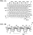
- FIG. 1A is a plan view of an automobile sound insulation panel to which the present invention is applied.
- FIG. 1B is a cross-sectional view taken on arrow A in FIG. 1A .
- FIG. 2A is a plan view of a second panel member included in the automobile sound insulation panel in FIG. 1 .
- FIG. 2B is a plan view of an elastic sheet member included in the automobile panel.
- FIG. 2C is a plan view of a first panel member included in the automobile panel member.
- an automobile sound insulation panel SI includes: a first panel member 1; a second panel member 2 positioned above the first panel member 1; and an elastic sheet member 3 positioned between the first panel member 1 and the second panel member 2.
- the elastic sheet member 3 includes a first projection-recess part 4 formed of a plurality of projections and recesses.
- the second panel member 2 abuts on the upper opening edge of each of the plurality of recesses 4A of the first projection-recess part 4.
- Respective units of inner space of the recesses 4A are individual air layers AG1 (first air layers) independent of one another.
- the opening at the upper plane of each recess 4A is positioned on the second panel member 2 side; and the individual air layer AG1 is the inner space of each recess 4A. Therefore, there are a plurality of individual air layers AG1 between the elastic sheet member 3 and the second panel member 2.
- each recess 4A and its periphery function as a vibration membrane 5 (a first vibration membrane) which can freely vibrate by any sound energy such as noises.
- the automobile sound insulation panel SI according to the present embodiment is capable of exhibiting the sound insulation effect surpassing the mass law without the necessity of, for example, increasing the weight of the second panel member 2.
- the vibration membranes 5 can isolate sounds particularly of a low frequency band by their vibrations.
- the elastic sheet member 3 is formed of, for example, an elastic material such as a rubber material, an elastomer resin material or the like.
- the whole elastic sheet member 3 may be formed of an elastic material.
- out of the whole elastic sheet member 3, particularly the sites which function as the vibration membranes 5, that is, the bottom and its periphery of each recess 4A may be partially formed of an elastic material.
- each recess 4A including the vibration membrane 5 may be changed as appropriate as necessary, so as to support the sound isolation-target frequency band.
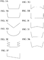
- the recess 4A may have the shape in FIGS. 3A to 3K .
- the recesses 4A of an identical size and shape successively provided by a predetermined pitch.
- the present invention is not limited thereto, and the recesses 4A may be varied in size, shape or pitch.
- the first panel member 1 includes a second projection-recess part 6 formed of a plurality of projections and recesses.
- the upper end surfaces of the plurality of projections 6A that form the second projection-recess part 6 abut on the elastic sheet member 3.
- a void part 7 is provided between two adjacent projections 6A, 6A out of the plurality of projections 6A.
- a plurality of such void parts 7 are successively provided, to form a continuous air layer AG2 (a second air layer) which is greater in volume than the individual air layers AG1.
- Each void part 7 is positioned between the first panel member 1 and the elastic sheet member 3. Accordingly, the continuous air layer AG2 formed of the plurality of void parts 7 is provided between the first panel member 1 and the elastic sheet member 3.
- each projection 6A is a truncated cone.
- the upper base surface of the truncated cone as the upper surface abuts on the elastic sheet member 3.
- the projections 6A support the whole elastic sheet member 3.
- each projection 6A is not specified to the truncated cone. While not illustrated, for example, the shape of each projection 6A may be a circular cylinder or a circular column, or a polygonal cylinder or a polygonal column (a triangular cylinder, a triangular column, a quadrangular column, a quadrangular cylinder). Alternatively, a stepped projection may be employed. The shape of each projection 6A can be changed as appropriate as necessary.
- the first panel member 1 may be formed of relatively hard resin.
- the taper of the truncated cone-shaped projection 6A can function as the draft gradient in removing the first panel member 1 from the mold assembly.
- a plurality of communication holes 8 are formed at the first panel member 1 in the automobile sound insulation panel SI according to the present embodiment.
- the communication holes 8 (hereinafter referred to as "the first communication holes 8-1") of the first panel member 1 are positioned among the projections 6A, and penetrate through the front and back surfaces of the first panel member 1 to communicate with the continuous air layer AG2.
- the plurality of first communication holes 8-1 and the continuous air layer AG2 form a first Helmholtz resonator.
- the resonance frequency of the first Helmholtz resonator is uniquely determined by the dimension and disposition interval (pitch) of the first communication holes 8-1 and the volume of the continuous air layer AG2.
- the resonance frequency of the first Helmholtz resonator can be adjusted (tuned) by changing the volume of the continuous air layer AG2, the dimension of the first communication holes 8-1, or the number or disposition interval of the first communication holes 8-1.
- each of the first communication holes 8-1 is not specified to a circle, and may be any of various shapes such as, for example, a long-hole shape, a semi-circular shape, a crescent shape, and a star shape.
- Each first communication hole 8-1 may have an identical inner diameter from its one end to the other end, or may be formed as a stepped or tapered hole having a varying inner diameter.
- the first communication holes 8-1 may each be provided between two adjacent ones of projections 6A, 6A as in FIG. 2C or by a plurality of pieces.
- the second panel member 2 is a resin plate of a predetermined thickness.
- the second panel member 2 also functions as a vibration membrane to exhibit the sound insulation effect. Accordingly, the material and thickness of the resin plate which is the second panel member 2 are changed as appropriate as necessary taking into consideration of the sound isolation-target frequency band.
- the second panel member 2 also is provided with the communication holes 8.
- the communication holes 8 of the second panel member 2 penetrate through the front and back surfaces of the second panel member 2 and communicate with corresponding one of the individual air layers AG1.
- one second communication hole 8-2 is provided for each individual air layer AG1.
- a plurality of second Helmholtz resonators are formed by the second communication holes 8-2 and corresponding ones of the individual air layers AG1.
- the resonance frequency of the second Helmholtz resonator is uniquely determined by the dimension of each second communication hole 8-2 and the volume of each individual air layer AG1.
- the resonance frequency of the second Helmholtz resonators can be adjusted (tuned) by changing the volume of the individual air layers AG1 or the dimension of the second communication holes 8-2.
- each of the second communication holes 8-2 is not specified to a circle, and may be any of various shapes such as, for example, a long-hole shape, a semi-circular shape, a crescent shape, and a star shape.
- Each second communication hole 8-2 may have an identical inner diameter from its one end to the other end, or may be formed as a stepped or tapered hole of varying inner diameter.
- the second communication holes 8-2 may be formed to pass through the center of the corresponding ones of the individual air layers AG1. Alternatively, the second communication holes 8-2 may be formed to be offset by a predetermined amount from the center. Furthermore, a plurality of second communication holes 8-2 may be formed for each individual air layer AG1.
- FIGS. 4 and 5 are explanatory illustrations of an automobile sound insulation panel according to the other embodiment of the present invention.
- FIG. 4 does not show the second panel member 2 and the elastic sheet member 3.
- the automobile sound insulation panel SI in FIG. 1B includes one continuous air layer AG2.
- the automobile sound insulation panel SI in FIG. 4 includes two continuous air layers AG2 which is obtained by provision of a partition 9 standing from the first panel member 1 toward the elastic sheet member 3.
- the partition 9 partitions the continuous air layer into two continuous air layers AG2.
- the number of the continuous air layers AG2 can be increased to three or more by increasing the number of the partition 9.
- the upper end surfaces of the projections 6A that form the second projection-recess part 6 are flat.
- a third projection-recess part 10 is formed at the upper end surface of each projection 6A.
- the inner space of a recess 10A that forms the third proj ection-recess part 10 is a third air layer 11 positioned between the first panel member 1 and the elastic sheet member 3.
- the automobile sound insulation panel SI in FIG. 5 includes the second vibration membranes 13 in addition to the first vibration membranes 5.
- the second vibration membranes 13 also contribute to isolating sounds of a particular low frequency band by their vibrations.
- the automobile sound insulation panel includes, as the specific structure, a first panel member 1, a second panel member 2, and an elastic sheet member 3 positioned between the first panel member 1 and the second panel member 2.
- the elastic sheet member 3 includes a first projection-recess part 4.
- the first panel member 1 abuts on respective upper opening edges of the plurality of recesses 4A that form the first projection-recess part 4.
- individual air layers AG1 exist between the second panel member 2 and the elastic sheet member 3.
- a continuous air layer AG2 exists.
- This structure brings about the following «Operation A» and «Operation B», suitably providing a lightweight automobile sound insulation panel with an expanded sound isolation-target frequency band and improved sound isolation performance.
- each recess 4A of the elastic sheet member 3 functioning as a vibration membrane, which can freely vibrate, effectively exhibits the sound insulation effect of the membrane vibration.
- the sound insulation effect surpassing the mass law is obtained without the necessity of, for example, increasing the weight of the second panel member 2.
- the vibration membranes can isolate sounds of a low frequency band.
- Provision of the communication holes 8 (8-1, 8-2) that communicate with the individual air layers AG1 and the continuous air layer AG2 allows the communication hole 8 and the individual air layers AG1 or the continuous air layer AG2 to exhibit the Helmholtz resonance.
- a combination of the resonance frequency and the n-th order resonance of the vibration membrane can address to sound isolation of a wider frequency range.
- the communication holes 8 (8-1) and the individual air layers AG1 When the Helmholtz resonance by the communication holes 8 (8-1) and the individual air layers AG1 is desired, the communication holes 8 (8-1) should be provided at the second panel member 2; when the Helmholtz resonance by the communication holes 8 (8-2) and the continuous air layer AG2 is desired, the communication holes 8 (8-2) should be provided at the first panel member 1. In these cases, no other panel member is stacked on the first panel member 1 or the second panel member 2. Accordingly, the openings of the communication holes 8 (8-1, 8-2) will not be closed and the sound insulation effect by the Helmholtz resonance is effectively exhibited.
- the present invention is not limited to the embodiment described above, and various modifications can be made by a person skilled in the art within the technical idea of the present invention.
- an embodiment omitting the communication holes 8 may be made.
Landscapes
- Physics & Mathematics (AREA)
- Engineering & Computer Science (AREA)
- Acoustics & Sound (AREA)
- Multimedia (AREA)
- Mechanical Engineering (AREA)
- Vehicle Interior And Exterior Ornaments, Soundproofing, And Insulation (AREA)
- Soundproofing, Sound Blocking, And Sound Damping (AREA)
Abstract
Description
- The present invention relates to an automobile sound insulation panel disposed at a site where sound isolation is needed, such as the floor of an automobile. In particular, the present invention relates to an automobile sound insulation panel which suitably implements a lightweight sound insulation panel with an expanded sound isolation-target frequency band and improved sound isolation performance.
- A sound insulation panel is disposed at a site in an automobile where sound isolation is needed, for example, a floor. A specific structure of the sound insulation panel of this type is disclosed in, for example,
Patent Literature 1. - The sound insulation panel disclosed in Patent Literature 1 (hereinafter referred to as "the conventional sound insulation panel") includes a hollow plate-like resin structure (10). The resin structure (10) includes a plurality of cells (S) juxtaposed to one another inside the resin structure (10), and communication holes (15) respectively communicating with the cells (S). The communication holes (15) and corresponding cells (S) provide the Helmholtz resonance.
- In the conventional sound insulation panel, a sheet member (50) is overlaid on the resin structure (10) to increase the weight of the whole sound insulation panel in an attempt to improve the sound isolation performance.
- Here, since the conventional technique increases the weight of the whole sound insulation panel by overlaying the sheet member (50) as means of improving the sound isolation performance, a reduction in weight of the whole sound insulation panel is hardly achieved.
- Additionally, in the conventional sound insulation panel, the overlaid sheet member (50) blocks the opening of each communication hole (15). This reduces the resonance of the Helmholtz resonance. Thus, the conventional sound insulation panel fails to effectively exhibit the sound insulation effect of the Helmholtz resonance. That is, the conventional technique fails to provide a sound insulation panel with improved sound isolation performance.
- Furthermore, while the conventional sound insulation panel is expected to exhibit the sound insulation effect by the membrane vibration of the sheet member (50) in the vicinity of the communication holes (15), it is difficult to control the vibration frequency of the membrane vibration. That is, the conventional technique fails to provide a sound insulation panel which supports sound isolation over a wide frequency band.
- Note that, the numbers in parentheses in the foregoing are the reference characters used in
Patent Literature 1. - Patent Literature 1:
Japanese Unexamined Patent Application Publication No. 2017-151325 - The present invention has been made to solve the problems above, and an object thereof is to provide an automobile sound insulation panel which suitably implements a lightweight sound insulation panel with an expanded sound isolation-target frequency band and improved sound isolation performance.
- In order to achieve the object, the present invention provides an automobile sound insulation panel including: a first panel member; a second panel member positioned above the first panel member; and an elastic sheet member positioned between the first panel member and the second panel member. The elastic sheet member includes a first projection-recess part formed of a plurality of projections and recesses, the second panel member abutting on respective upper opening edges of the plurality of recesses forming the first projection-recess part. The first panel member includes a second projection-recess part formed of a plurality of projections and recesses, respective upper end surfaces of the plurality of projections forming the second projection-recess part abutting on the elastic sheet member. Between the second panel member and the elastic sheet member, respective units of inner space of the plurality of recesses exist as individual air layers independent of one another. Between the first panel member and the elastic sheet member, a plurality of void parts each positioned between two adjacent ones of the plurality of projections are successively provided, to form a continuous air layer greater in volume than the individual air layers.
- In the present invention, a bottom of each of the recesses of the elastic sheet member may function as a vibration membrane which is capable of freely vibrating.
- In the present invention, the automobile sound insulation panel further includes communication holes communicating with the individual air layers or the continuous air layer. Each of the communication holes and each of the individual air layers or the continuous air layer form a Helmholtz resonator.
- The specific structure of the present invention is, as described above, an automobile sound insulation panel that includes a first panel member, a second panel member, and an elastic sheet member positioned between the first panel member and the second panel member. The elastic sheet member includes a first projection-recess part formed of a plurality of projections and recesses. The first panel member abuts on respective upper opening edges of the plurality of recesses that form the first projection-recess part. Between the second panel member and the elastic sheet member, individual air layers exist. Between the first panel member and the elastic sheet member, a continuous air layer exists. This structure brings about the following <<Operation A>> and <<Operation B>>, suitably providing an automobile sound insulation panel which suitably implements a lightweight sound insulation panel with an expanded sound isolation-target frequency band and improved sound isolation performance.
- The bottom of each recess of the elastic sheet member functioning as a vibration membrane, which can freely vibrate, effectively exhibits the sound insulation effect of the membrane vibration. The sound insulation effect surpassing the mass law is obtained without the necessity of, for example, increasing the weight of the second panel member. Furthermore, the vibration membrane can isolate sounds of a low frequency band.
- Provision of the communication holes that communicate with the individual air layers or the continuous air layer allows the communication holes and the individual air layers or the continuous air layer to exhibit the Helmholtz resonance. A combination of the resonance frequency and the n-th order resonance of the vibration membrane can address to sound isolation of a wider frequency range.
- When the Helmholtz resonance by the communication holes and the individual air layers is desired, the communication holes should be provided at the second panel member; when the Helmholtz resonance by the communication holes and the continuous air layer is desired, the communication holes should be provided at the first panel member. In these cases, no other panel member is stacked on the first panel member or the second panel member. Accordingly, the openings of the communication holes will not be closed and the sound insulation effect by the Helmholtz resonance is effectively exhibited.
-
-
FIG. 1A is a plan view of an automobile sound insulation panel to which the present invention is applied. -
FIG. 1B is a cross-sectional view taken on arrow A inFIG. 1A . -
FIG. 2A is a plan view of a second panel member included in the automobile sound insulation panel inFIG. 1 . -
FIG. 2B is a plan view of an elastic sheet member included in the automobile panel. -
FIG. 2C is a plan view of a first panel member included in the automobile panel member. -
FIG. 3 is an explanatory illustration of a variation of the shape of recesses that form a first projection-recess part. -
FIG. 4 is an explanatory illustration of other embodiment of the present invention. -
FIG. 5 is an explanatory illustration of other embodiment of the present invention. - In the following, with reference to the accompanying drawings, a description will be given of the best mode for carrying out the present invention.
-
FIG. 1A is a plan view of an automobile sound insulation panel to which the present invention is applied.FIG. 1B is a cross-sectional view taken on arrow A inFIG. 1A .FIG. 2A is a plan view of a second panel member included in the automobile sound insulation panel inFIG. 1 .FIG. 2B is a plan view of an elastic sheet member included in the automobile panel.FIG. 2C is a plan view of a first panel member included in the automobile panel member. - With reference to
FIGS. 1A and 1B , an automobile sound insulation panel SI according to the present embodiment includes: afirst panel member 1; asecond panel member 2 positioned above thefirst panel member 1; and anelastic sheet member 3 positioned between thefirst panel member 1 and thesecond panel member 2. - The
elastic sheet member 3 includes a first projection-recess part 4 formed of a plurality of projections and recesses. Thesecond panel member 2 abuts on the upper opening edge of each of the plurality ofrecesses 4A of the first projection-recess part 4. - Respective units of inner space of the
recesses 4A are individual air layers AG1 (first air layers) independent of one another. The opening at the upper plane of eachrecess 4A is positioned on thesecond panel member 2 side; and the individual air layer AG1 is the inner space of eachrecess 4A. Therefore, there are a plurality of individual air layers AG1 between theelastic sheet member 3 and thesecond panel member 2. - The bottom of each
recess 4A and its periphery function as a vibration membrane 5 (a first vibration membrane) which can freely vibrate by any sound energy such as noises. Thus, the automobile sound insulation panel SI according to the present embodiment is capable of exhibiting the sound insulation effect surpassing the mass law without the necessity of, for example, increasing the weight of thesecond panel member 2. Furthermore, thevibration membranes 5 can isolate sounds particularly of a low frequency band by their vibrations. - As means for realizing the function as the
vibration membranes 5 in theelastic sheet member 3, theelastic sheet member 3 is formed of, for example, an elastic material such as a rubber material, an elastomer resin material or the like. In this case, the wholeelastic sheet member 3 may be formed of an elastic material. Alternatively, out of the wholeelastic sheet member 3, particularly the sites which function as thevibration membranes 5, that is, the bottom and its periphery of eachrecess 4A may be partially formed of an elastic material. - The shape of each
recess 4A including thevibration membrane 5 may be changed as appropriate as necessary, so as to support the sound isolation-target frequency band. For example, therecess 4A may have the shape inFIGS. 3A to 3K . - With reference to
FIG. 2B , in the automobile sound insulation panel SI according to the present embodiment, as a specific structure example of the first projection-recess part 4 in theelastic sheet member 3, therecesses 4A of an identical size and shape successively provided by a predetermined pitch. The present invention is not limited thereto, and therecesses 4A may be varied in size, shape or pitch. - The
first panel member 1 includes a second projection-recess part 6 formed of a plurality of projections and recesses. The upper end surfaces of the plurality ofprojections 6A that form the second projection-recess part 6 abut on theelastic sheet member 3. - A
void part 7 is provided between twoadjacent projections projections 6A. A plurality of suchvoid parts 7 are successively provided, to form a continuous air layer AG2 (a second air layer) which is greater in volume than the individual air layers AG1. - Each
void part 7 is positioned between thefirst panel member 1 and theelastic sheet member 3. Accordingly, the continuous air layer AG2 formed of the plurality ofvoid parts 7 is provided between thefirst panel member 1 and theelastic sheet member 3. - In the automobile sound insulation panel SI according to the present embodiment, a specific exemplary shape of each
projection 6A is a truncated cone. The upper base surface of the truncated cone as the upper surface abuts on theelastic sheet member 3. Thus, theprojections 6A support the wholeelastic sheet member 3. - The shape of each
projection 6A is not specified to the truncated cone. While not illustrated, for example, the shape of eachprojection 6A may be a circular cylinder or a circular column, or a polygonal cylinder or a polygonal column (a triangular cylinder, a triangular column, a quadrangular column, a quadrangular cylinder). Alternatively, a stepped projection may be employed. The shape of eachprojection 6A can be changed as appropriate as necessary. - The
first panel member 1 may be formed of relatively hard resin. When thefirst panel member 1 is formed using a mold assembly, the taper of the truncated cone-shapedprojection 6A can function as the draft gradient in removing thefirst panel member 1 from the mold assembly. - With reference to
FIGS. 1A, 1B , and2C , a plurality ofcommunication holes 8 are formed at thefirst panel member 1 in the automobile sound insulation panel SI according to the present embodiment. The communication holes 8 (hereinafter referred to as "the first communication holes 8-1") of thefirst panel member 1 are positioned among theprojections 6A, and penetrate through the front and back surfaces of thefirst panel member 1 to communicate with the continuous air layer AG2. - In the automobile sound insulation panel SI according to the present embodiment, the plurality of first communication holes 8-1 and the continuous air layer AG2 form a first Helmholtz resonator. The resonance frequency of the first Helmholtz resonator is uniquely determined by the dimension and disposition interval (pitch) of the first communication holes 8-1 and the volume of the continuous air layer AG2.
- Accordingly, in the automobile sound insulation panel SI according to the present embodiment, for example, the resonance frequency of the first Helmholtz resonator can be adjusted (tuned) by changing the volume of the continuous air layer AG2, the dimension of the first communication holes 8-1, or the number or disposition interval of the first communication holes 8-1.
- The cross-sectional shape of each of the first communication holes 8-1 is not specified to a circle, and may be any of various shapes such as, for example, a long-hole shape, a semi-circular shape, a crescent shape, and a star shape. Each first communication hole 8-1 may have an identical inner diameter from its one end to the other end, or may be formed as a stepped or tapered hole having a varying inner diameter. Furthermore, the first communication holes 8-1 may each be provided between two adjacent ones of
projections FIG. 2C or by a plurality of pieces. - The
second panel member 2 is a resin plate of a predetermined thickness. Thesecond panel member 2 also functions as a vibration membrane to exhibit the sound insulation effect. Accordingly, the material and thickness of the resin plate which is thesecond panel member 2 are changed as appropriate as necessary taking into consideration of the sound isolation-target frequency band. - With reference to
FIGS. 1A, 1B , and2A , in the automobile sound insulation panel SI according to the present embodiment, as a specific configuration example of thesecond panel member 2, thesecond panel member 2 also is provided with the communication holes 8. The communication holes 8 of the second panel member 2 (hereinafter referred to as "the second communication holes 8-2") penetrate through the front and back surfaces of thesecond panel member 2 and communicate with corresponding one of the individual air layers AG1. - That is, one second communication hole 8-2 is provided for each individual air layer AG1. In the automobile sound insulation panel SI according to the present embodiment, a plurality of second Helmholtz resonators are formed by the second communication holes 8-2 and corresponding ones of the individual air layers AG1. The resonance frequency of the second Helmholtz resonator is uniquely determined by the dimension of each second communication hole 8-2 and the volume of each individual air layer AG1.
- Accordingly, in the automobile sound insulation panel SI according to the present embodiment, the resonance frequency of the second Helmholtz resonators can be adjusted (tuned) by changing the volume of the individual air layers AG1 or the dimension of the second communication holes 8-2.
- Similarly to the first communication holes 8-1, the cross-sectional shape of each of the second communication holes 8-2 is not specified to a circle, and may be any of various shapes such as, for example, a long-hole shape, a semi-circular shape, a crescent shape, and a star shape. Each second communication hole 8-2 may have an identical inner diameter from its one end to the other end, or may be formed as a stepped or tapered hole of varying inner diameter. As in
FIG. 1B , the second communication holes 8-2 may be formed to pass through the center of the corresponding ones of the individual air layers AG1. Alternatively, the second communication holes 8-2 may be formed to be offset by a predetermined amount from the center. Furthermore, a plurality of second communication holes 8-2 may be formed for each individual air layer AG1. -
FIGS. 4 and5 are explanatory illustrations of an automobile sound insulation panel according to the other embodiment of the present invention. For the sake of convenience,FIG. 4 does not show thesecond panel member 2 and theelastic sheet member 3. - The automobile sound insulation panel SI in
FIG. 1B includes one continuous air layer AG2. Here, the automobile sound insulation panel SI inFIG. 4 includes two continuous air layers AG2 which is obtained by provision of apartition 9 standing from thefirst panel member 1 toward theelastic sheet member 3. Thepartition 9 partitions the continuous air layer into two continuous air layers AG2. The number of the continuous air layers AG2 can be increased to three or more by increasing the number of thepartition 9. - In the automobile sound insulation panel SI in
FIG. 1B , the upper end surfaces of theprojections 6A that form the second projection-recess part 6 are flat. Here, in the automobile sound insulation panel SI inFIG. 5 , a third projection-recess part 10 is formed at the upper end surface of eachprojection 6A. The inner space of arecess 10A that forms the third proj ection-recess part 10 is a third air layer 11 positioned between thefirst panel member 1 and theelastic sheet member 3. - In the automobile sound insulation panel SI in
FIG. 5 , in the wholesecond panel member 1, concaves 12 are formed at the plane that opposes to the third air layer 11 via theelastic sheet member 3. Thus, in each range where the third air layer 11 and the concave 12 oppose to each other, part of theelastic sheet member 3 can freely vibrate as asecond vibration membrane 13. - That is, the automobile sound insulation panel SI in
FIG. 5 includes thesecond vibration membranes 13 in addition to thefirst vibration membranes 5. Thesecond vibration membranes 13 also contribute to isolating sounds of a particular low frequency band by their vibrations. - The automobile sound insulation panel according to the embodiments described above includes, as the specific structure, a
first panel member 1, asecond panel member 2, and anelastic sheet member 3 positioned between thefirst panel member 1 and thesecond panel member 2. Theelastic sheet member 3 includes a first projection-recess part 4. Thefirst panel member 1 abuts on respective upper opening edges of the plurality ofrecesses 4A that form the first projection-recess part 4. Between thesecond panel member 2 and theelastic sheet member 3, individual air layers AG1 exist. Between thefirst panel member 1 and theelastic sheet member 3, a continuous air layer AG2 exists. This structure brings about the following «Operation A» and «Operation B», suitably providing a lightweight automobile sound insulation panel with an expanded sound isolation-target frequency band and improved sound isolation performance. - The bottom of each
recess 4A of theelastic sheet member 3 functioning as a vibration membrane, which can freely vibrate, effectively exhibits the sound insulation effect of the membrane vibration. The sound insulation effect surpassing the mass law is obtained without the necessity of, for example, increasing the weight of thesecond panel member 2. Furthermore, the vibration membranes can isolate sounds of a low frequency band. - Provision of the communication holes 8 (8-1, 8-2) that communicate with the individual air layers AG1 and the continuous air layer AG2 allows the
communication hole 8 and the individual air layers AG1 or the continuous air layer AG2 to exhibit the Helmholtz resonance. A combination of the resonance frequency and the n-th order resonance of the vibration membrane can address to sound isolation of a wider frequency range. - When the Helmholtz resonance by the communication holes 8 (8-1) and the individual air layers AG1 is desired, the communication holes 8 (8-1) should be provided at the
second panel member 2; when the Helmholtz resonance by the communication holes 8 (8-2) and the continuous air layer AG2 is desired, the communication holes 8 (8-2) should be provided at thefirst panel member 1. In these cases, no other panel member is stacked on thefirst panel member 1 or thesecond panel member 2. Accordingly, the openings of the communication holes 8 (8-1, 8-2) will not be closed and the sound insulation effect by the Helmholtz resonance is effectively exhibited. - The present invention is not limited to the embodiment described above, and various modifications can be made by a person skilled in the art within the technical idea of the present invention. For example, an embodiment omitting the communication holes 8 may be made.
-
- 1 first panel member
- 2 second panel member
- 3 elastic sheet member
- 4 first projection-recess part
- 4A recess of first projection-recess part
- 5 vibration membrane (first vibration membrane)
- 6 second projection-recess part
- 6A projection of second projection-recess part
- 7 void part
- 8 communication hole
- 8-1 first communication hole
- 8-2 second communication hole
- 9 partition
- 10 third projection-recess part
- 10A recess of third projection-recess part
- 11 third air layer
- 12 concave
- 13 second vibration membrane
- AG1 individual air layer (first air layer)
- AG2 continuous air layer (second air layer)
- SI automobile sound insulation panel
Claims (3)
- An automobile sound insulation panel comprising:a first panel member;a second panel member positioned above the first panel member; andan elastic sheet member positioned between the first panel member and the second panel member, whereinthe elastic sheet member includes a first projection-recess part formed of a plurality of projections and recesses, the second panel member abutting on respective upper opening edges of the plurality of recesses forming the first projection-recess part,the first panel member includes a second projection-recess part formed of a plurality of projections and recesses, respective upper end surfaces of the plurality of projections forming the second projection-recess part abutting on the elastic sheet member,between the second panel member and the elastic sheet member, respective units of inner space of the plurality of recesses exist as individual air layers independent of one another, andbetween the first panel member and the elastic sheet member, a plurality of void parts each positioned between two adjacent ones of the plurality of projections are successively provided, to form a continuous air layer greater in volume than the individual air layers.
- The automobile sound insulation panel according to claim 1, wherein a bottom of each of the recesses of the elastic sheet member functions as a vibration membrane which is capable of freely vibrating.
- The automobile sound insulation panel according to claim 2, further comprising communication holes communicating with the individual air layers or the continuous air layer, wherein each of the communication holes and each of the individual air layers or the continuous air layer form a Helmholtz resonator.
Applications Claiming Priority (1)
| Application Number | Priority Date | Filing Date | Title |
|---|---|---|---|
| PCT/JP2018/035328 WO2020065705A1 (en) | 2018-09-25 | 2018-09-25 | Automobile sound insulation panel |
Publications (3)
| Publication Number | Publication Date |
|---|---|
| EP3858680A1 true EP3858680A1 (en) | 2021-08-04 |
| EP3858680A4 EP3858680A4 (en) | 2022-04-20 |
| EP3858680B1 EP3858680B1 (en) | 2024-04-17 |
Family
ID=69953431
Family Applications (1)
| Application Number | Title | Priority Date | Filing Date |
|---|---|---|---|
| EP18934661.2A Active EP3858680B1 (en) | 2018-09-25 | 2018-09-25 | Automobile sound insulation panel |
Country Status (5)
| Country | Link |
|---|---|
| US (1) | US11780384B2 (en) |
| EP (1) | EP3858680B1 (en) |
| JP (1) | JP6738499B1 (en) |
| CN (1) | CN112805184B (en) |
| WO (1) | WO2020065705A1 (en) |
Families Citing this family (6)
| Publication number | Priority date | Publication date | Assignee | Title |
|---|---|---|---|---|
| FR3088905A1 (en) * | 2018-11-28 | 2020-05-29 | Airbus Operations (S.A.S.) | Sound absorption structure comprising a liquid drainage system and propellant assembly comprising such a sound absorption structure |
| JP7605620B2 (en) * | 2020-12-01 | 2024-12-24 | 株式会社イノアックコーポレーション | Sound absorbing and insulating materials |
| EP4318461A4 (en) * | 2021-03-31 | 2024-08-14 | Mitsubishi Chemical Corporation | SOUND-INSULATING PANEL ELEMENT AND SOUND-INSULATING STRUCTURE |
| US12269245B2 (en) * | 2021-09-20 | 2025-04-08 | Airbus Operations Sas | Acoustic treatment panel comprising acoustic cells of different volumes obtained from cylindrical and identical main tubes, aircraft comprising such an acoustic treatment panel |
| USD1116534S1 (en) * | 2023-01-19 | 2026-03-10 | STP North America LLC | Sound deadening mat for use in transportation units |
| CN118621924A (en) * | 2024-07-05 | 2024-09-10 | 常熟理工学院 | A composite damping lightweight sound insulation wall |
Family Cites Families (26)
| Publication number | Priority date | Publication date | Assignee | Title |
|---|---|---|---|---|
| US4335802A (en) * | 1979-10-31 | 1982-06-22 | The Soundcoat Company, Inc. | Sound absorbing material |
| DE19910595A1 (en) | 1999-03-10 | 2000-09-21 | Volkswagen Ag | Airborne sound-absorbing molded part |
| JP3649380B2 (en) * | 1999-03-17 | 2005-05-18 | 本田技研工業株式会社 | Vehicle roofing |
| JP2000272439A (en) * | 1999-03-26 | 2000-10-03 | Tokai Rubber Ind Ltd | Sound insulation front grill panel, sound absorbing bumper and exterior noise reduction device |
| JP4291760B2 (en) * | 2003-09-05 | 2009-07-08 | 株式会社神戸製鋼所 | Sound absorbing structure and manufacturing method thereof |
| WO2005045225A1 (en) * | 2003-11-06 | 2005-05-19 | Mahle Tennex Corporation | Intake device of internal combustion engine |
| CN102481760B (en) * | 2009-08-11 | 2016-02-24 | 夏伊洛工业公司 | Sheet metal components |
| JP4981880B2 (en) * | 2009-11-30 | 2012-07-25 | 株式会社神戸製鋼所 | Soundproofing material and soundproofing system |
| EP2593614B1 (en) * | 2010-07-13 | 2016-04-13 | Bellmax Acoustic Pty Ltd | An acoustic panel |
| KR101206512B1 (en) * | 2010-09-17 | 2012-11-29 | 강원대학교산학협력단 | corrugated steel plate with cross type crease |
| US8770343B2 (en) * | 2011-11-23 | 2014-07-08 | The Boeing Company | Noise reduction system for composite structures |
| DE102011120979A1 (en) * | 2011-12-13 | 2013-06-13 | Rolls-Royce Deutschland Ltd & Co Kg | Acoustic absorber |
| JP6165466B2 (en) * | 2013-02-27 | 2017-07-19 | 株式会社神戸製鋼所 | Soundproof structure |
| JP2015074358A (en) * | 2013-10-09 | 2015-04-20 | 河西工業株式会社 | Damping reinforcement |
| EP3896686B1 (en) * | 2016-02-04 | 2023-12-27 | Mitsubishi Chemical Corporation | Sound insulation structure using a sound insulation sheet member |
| JP6669528B2 (en) | 2016-02-25 | 2020-03-18 | 岐阜プラスチック工業株式会社 | Sound insulation panel |
| JP6636471B2 (en) * | 2017-02-16 | 2020-01-29 | 株式会社ニフコ | Sound absorber and sound absorbing structure |
| KR102296996B1 (en) * | 2017-03-22 | 2021-09-02 | 현대자동차주식회사 | Non woven fabric for vehicle interior part, manufactufing method of the same and cargo screen for vehicle using the non woven fabric for vehicle interior part |
| FR3065570B1 (en) * | 2017-04-21 | 2019-05-03 | Office National D'etudes Et De Recherches Aerospatiales | SURFACIAL TRIM FOR ACOUSTIC ABSORPTION |
| EP3761304A4 (en) * | 2018-02-27 | 2021-04-21 | FUJIFILM Corporation | SOUND INSULATION STRUCTURE |
| JP7172457B2 (en) * | 2018-11-05 | 2022-11-16 | ヤマハ株式会社 | Sound-absorbing units and sound-absorbing structures |
| DE102019108169A1 (en) * | 2019-03-29 | 2020-10-01 | Röchling Automotive SE & Co. KG | Vehicle underbody cladding for the absorption of rolling noise on the vehicle clad with it |
| US11434819B2 (en) * | 2019-03-29 | 2022-09-06 | General Electric Company | Acoustic liners with enhanced acoustic absorption and reduced drag characteristics |
| FR3099963A1 (en) * | 2019-08-13 | 2021-02-19 | Airbus Operations | Acoustic element with double enclosure and reduced bulk, in particular for aircraft acoustic panels |
| US11626094B2 (en) * | 2020-03-03 | 2023-04-11 | Toyota Motor Engineering & Manufacturing, Inc. | Membrane acoustic absorber |
| FR3117658B1 (en) * | 2020-12-15 | 2023-08-11 | Safran Aircraft Engines | Reduced footprint acoustic treatment panel for turbojet engine |
-
2018
- 2018-09-25 EP EP18934661.2A patent/EP3858680B1/en active Active
- 2018-09-25 JP JP2019554422A patent/JP6738499B1/en active Active
- 2018-09-25 WO PCT/JP2018/035328 patent/WO2020065705A1/en not_active Ceased
- 2018-09-25 US US17/056,871 patent/US11780384B2/en active Active
- 2018-09-25 CN CN201880092593.5A patent/CN112805184B/en active Active
Also Published As
| Publication number | Publication date |
|---|---|
| WO2020065705A1 (en) | 2020-04-02 |
| JP6738499B1 (en) | 2020-08-12 |
| EP3858680A4 (en) | 2022-04-20 |
| JPWO2020065705A1 (en) | 2021-01-07 |
| US11780384B2 (en) | 2023-10-10 |
| CN112805184B (en) | 2023-09-08 |
| US20210146861A1 (en) | 2021-05-20 |
| CN112805184A (en) | 2021-05-14 |
| EP3858680B1 (en) | 2024-04-17 |
Similar Documents
| Publication | Publication Date | Title |
|---|---|---|
| EP3858680A1 (en) | Automobile sound insulation panel | |
| US7743884B2 (en) | Sandwich panel for sound absorption | |
| JP5988874B2 (en) | Loudspeaker assembly and system | |
| US3831710A (en) | Sound absorbing panel | |
| US9222229B1 (en) | Tunable sandwich-structured acoustic barriers | |
| CN108346421A (en) | A kind of honeycomb interlayer sound absorption structure of built-in microperforated panel | |
| US20170070811A1 (en) | Electronic device including acoustically isolated serpentine port and related methods | |
| JP2009198902A (en) | Sound absorbing structure, sound absorbing structure group, acoustic chamber, method of adjusting sound absorbing structure and noise reduction method | |
| US1972563A (en) | Acoustic construction | |
| US20160365079A1 (en) | High and low frequency sound absorption assembly | |
| US9602899B2 (en) | Speaker and its production method | |
| JPH0850489A (en) | Sound absorbing structure | |
| JPH10254455A (en) | Sound insulation board structure | |
| CN217935867U (en) | Loudspeaker | |
| JP2000330571A (en) | Sound absorbing structure | |
| US12073817B2 (en) | Sound absorbing member, sound absorbing apparatus, and sound absorbing structure | |
| JPH0271292A (en) | Carrying and/or holding device for percussion instrument | |
| CN105957513A (en) | Plate-type broadband sound insulation component | |
| JP7385338B2 (en) | Automotive sound insulation panel | |
| US20170068317A1 (en) | Electronic device including selectively operable audio output transducers of transducer port/radiator pairs and related methods | |
| JP2010097147A (en) | Sound absorbing structure, sound absorbing structure group and acoustic room | |
| JP2009204836A (en) | Sound absorption structure, sound absorption structure group, sound box, method of adjusting sound structure and noise reduction method | |
| JP7394673B2 (en) | Automotive sound insulation panel | |
| CN203446014U (en) | Drum paper structure and loudspeaker | |
| CN120057283A (en) | Acoustic liner and aeroengine |
Legal Events
| Date | Code | Title | Description |
|---|---|---|---|
| STAA | Information on the status of an ep patent application or granted ep patent |
Free format text: STATUS: THE INTERNATIONAL PUBLICATION HAS BEEN MADE |
|
| PUAI | Public reference made under article 153(3) epc to a published international application that has entered the european phase |
Free format text: ORIGINAL CODE: 0009012 |
|
| STAA | Information on the status of an ep patent application or granted ep patent |
Free format text: STATUS: REQUEST FOR EXAMINATION WAS MADE |
|
| 17P | Request for examination filed |
Effective date: 20210208 |
|
| AK | Designated contracting states |
Kind code of ref document: A1 Designated state(s): AL AT BE BG CH CY CZ DE DK EE ES FI FR GB GR HR HU IE IS IT LI LT LU LV MC MK MT NL NO PL PT RO RS SE SI SK SM TR |
|
| DAV | Request for validation of the european patent (deleted) | ||
| DAX | Request for extension of the european patent (deleted) | ||
| A4 | Supplementary search report drawn up and despatched |
Effective date: 20220321 |
|
| RIC1 | Information provided on ipc code assigned before grant |
Ipc: G10K 11/168 20060101ALI20220315BHEP Ipc: G10K 11/16 20060101ALI20220315BHEP Ipc: G10K 11/172 20060101ALI20220315BHEP Ipc: B60R 13/08 20060101AFI20220315BHEP |
|
| GRAP | Despatch of communication of intention to grant a patent |
Free format text: ORIGINAL CODE: EPIDOSNIGR1 |
|
| STAA | Information on the status of an ep patent application or granted ep patent |
Free format text: STATUS: GRANT OF PATENT IS INTENDED |
|
| INTG | Intention to grant announced |
Effective date: 20231206 |
|
| GRAS | Grant fee paid |
Free format text: ORIGINAL CODE: EPIDOSNIGR3 |
|
| GRAA | (expected) grant |
Free format text: ORIGINAL CODE: 0009210 |
|
| STAA | Information on the status of an ep patent application or granted ep patent |
Free format text: STATUS: THE PATENT HAS BEEN GRANTED |
|
| AK | Designated contracting states |
Kind code of ref document: B1 Designated state(s): AL AT BE BG CH CY CZ DE DK EE ES FI FR GB GR HR HU IE IS IT LI LT LU LV MC MK MT NL NO PL PT RO RS SE SI SK SM TR |
|
| REG | Reference to a national code |
Ref country code: GB Ref legal event code: FG4D |
|
| REG | Reference to a national code |
Ref country code: CH Ref legal event code: EP |
|
| REG | Reference to a national code |
Ref country code: DE Ref legal event code: R096 Ref document number: 602018068405 Country of ref document: DE |
|
| REG | Reference to a national code |
Ref country code: IE Ref legal event code: FG4D |
|
| REG | Reference to a national code |
Ref country code: LT Ref legal event code: MG9D |
|
| REG | Reference to a national code |
Ref country code: NL Ref legal event code: MP Effective date: 20240417 |
|
| REG | Reference to a national code |
Ref country code: AT Ref legal event code: MK05 Ref document number: 1676967 Country of ref document: AT Kind code of ref document: T Effective date: 20240417 |
|
| PG25 | Lapsed in a contracting state [announced via postgrant information from national office to epo] |
Ref country code: NL Free format text: LAPSE BECAUSE OF FAILURE TO SUBMIT A TRANSLATION OF THE DESCRIPTION OR TO PAY THE FEE WITHIN THE PRESCRIBED TIME-LIMIT Effective date: 20240417 |
|
| PG25 | Lapsed in a contracting state [announced via postgrant information from national office to epo] |
Ref country code: NL Free format text: LAPSE BECAUSE OF FAILURE TO SUBMIT A TRANSLATION OF THE DESCRIPTION OR TO PAY THE FEE WITHIN THE PRESCRIBED TIME-LIMIT Effective date: 20240417 |
|
| PG25 | Lapsed in a contracting state [announced via postgrant information from national office to epo] |
Ref country code: IS Free format text: LAPSE BECAUSE OF FAILURE TO SUBMIT A TRANSLATION OF THE DESCRIPTION OR TO PAY THE FEE WITHIN THE PRESCRIBED TIME-LIMIT Effective date: 20240817 |
|
| PG25 | Lapsed in a contracting state [announced via postgrant information from national office to epo] |
Ref country code: BG Free format text: LAPSE BECAUSE OF FAILURE TO SUBMIT A TRANSLATION OF THE DESCRIPTION OR TO PAY THE FEE WITHIN THE PRESCRIBED TIME-LIMIT Effective date: 20240417 |
|
| PG25 | Lapsed in a contracting state [announced via postgrant information from national office to epo] |
Ref country code: HR Free format text: LAPSE BECAUSE OF FAILURE TO SUBMIT A TRANSLATION OF THE DESCRIPTION OR TO PAY THE FEE WITHIN THE PRESCRIBED TIME-LIMIT Effective date: 20240417 Ref country code: FI Free format text: LAPSE BECAUSE OF FAILURE TO SUBMIT A TRANSLATION OF THE DESCRIPTION OR TO PAY THE FEE WITHIN THE PRESCRIBED TIME-LIMIT Effective date: 20240417 |
|
| PG25 | Lapsed in a contracting state [announced via postgrant information from national office to epo] |
Ref country code: GR Free format text: LAPSE BECAUSE OF FAILURE TO SUBMIT A TRANSLATION OF THE DESCRIPTION OR TO PAY THE FEE WITHIN THE PRESCRIBED TIME-LIMIT Effective date: 20240718 |
|
| PG25 | Lapsed in a contracting state [announced via postgrant information from national office to epo] |
Ref country code: PT Free format text: LAPSE BECAUSE OF FAILURE TO SUBMIT A TRANSLATION OF THE DESCRIPTION OR TO PAY THE FEE WITHIN THE PRESCRIBED TIME-LIMIT Effective date: 20240819 |
|
| PG25 | Lapsed in a contracting state [announced via postgrant information from national office to epo] |
Ref country code: ES Free format text: LAPSE BECAUSE OF FAILURE TO SUBMIT A TRANSLATION OF THE DESCRIPTION OR TO PAY THE FEE WITHIN THE PRESCRIBED TIME-LIMIT Effective date: 20240417 |
|
| PG25 | Lapsed in a contracting state [announced via postgrant information from national office to epo] |
Ref country code: AT Free format text: LAPSE BECAUSE OF FAILURE TO SUBMIT A TRANSLATION OF THE DESCRIPTION OR TO PAY THE FEE WITHIN THE PRESCRIBED TIME-LIMIT Effective date: 20240417 |
|
| PG25 | Lapsed in a contracting state [announced via postgrant information from national office to epo] |
Ref country code: PL Free format text: LAPSE BECAUSE OF FAILURE TO SUBMIT A TRANSLATION OF THE DESCRIPTION OR TO PAY THE FEE WITHIN THE PRESCRIBED TIME-LIMIT Effective date: 20240417 |
|
| PG25 | Lapsed in a contracting state [announced via postgrant information from national office to epo] |
Ref country code: LV Free format text: LAPSE BECAUSE OF FAILURE TO SUBMIT A TRANSLATION OF THE DESCRIPTION OR TO PAY THE FEE WITHIN THE PRESCRIBED TIME-LIMIT Effective date: 20240417 |
|
| PG25 | Lapsed in a contracting state [announced via postgrant information from national office to epo] |
Ref country code: PT Free format text: LAPSE BECAUSE OF FAILURE TO SUBMIT A TRANSLATION OF THE DESCRIPTION OR TO PAY THE FEE WITHIN THE PRESCRIBED TIME-LIMIT Effective date: 20240819 Ref country code: PL Free format text: LAPSE BECAUSE OF FAILURE TO SUBMIT A TRANSLATION OF THE DESCRIPTION OR TO PAY THE FEE WITHIN THE PRESCRIBED TIME-LIMIT Effective date: 20240417 Ref country code: NO Free format text: LAPSE BECAUSE OF FAILURE TO SUBMIT A TRANSLATION OF THE DESCRIPTION OR TO PAY THE FEE WITHIN THE PRESCRIBED TIME-LIMIT Effective date: 20240717 Ref country code: LV Free format text: LAPSE BECAUSE OF FAILURE TO SUBMIT A TRANSLATION OF THE DESCRIPTION OR TO PAY THE FEE WITHIN THE PRESCRIBED TIME-LIMIT Effective date: 20240417 Ref country code: IS Free format text: LAPSE BECAUSE OF FAILURE TO SUBMIT A TRANSLATION OF THE DESCRIPTION OR TO PAY THE FEE WITHIN THE PRESCRIBED TIME-LIMIT Effective date: 20240817 Ref country code: HR Free format text: LAPSE BECAUSE OF FAILURE TO SUBMIT A TRANSLATION OF THE DESCRIPTION OR TO PAY THE FEE WITHIN THE PRESCRIBED TIME-LIMIT Effective date: 20240417 Ref country code: GR Free format text: LAPSE BECAUSE OF FAILURE TO SUBMIT A TRANSLATION OF THE DESCRIPTION OR TO PAY THE FEE WITHIN THE PRESCRIBED TIME-LIMIT Effective date: 20240718 Ref country code: FI Free format text: LAPSE BECAUSE OF FAILURE TO SUBMIT A TRANSLATION OF THE DESCRIPTION OR TO PAY THE FEE WITHIN THE PRESCRIBED TIME-LIMIT Effective date: 20240417 Ref country code: ES Free format text: LAPSE BECAUSE OF FAILURE TO SUBMIT A TRANSLATION OF THE DESCRIPTION OR TO PAY THE FEE WITHIN THE PRESCRIBED TIME-LIMIT Effective date: 20240417 Ref country code: BG Free format text: LAPSE BECAUSE OF FAILURE TO SUBMIT A TRANSLATION OF THE DESCRIPTION OR TO PAY THE FEE WITHIN THE PRESCRIBED TIME-LIMIT Effective date: 20240417 Ref country code: AT Free format text: LAPSE BECAUSE OF FAILURE TO SUBMIT A TRANSLATION OF THE DESCRIPTION OR TO PAY THE FEE WITHIN THE PRESCRIBED TIME-LIMIT Effective date: 20240417 Ref country code: RS Free format text: LAPSE BECAUSE OF FAILURE TO SUBMIT A TRANSLATION OF THE DESCRIPTION OR TO PAY THE FEE WITHIN THE PRESCRIBED TIME-LIMIT Effective date: 20240717 |
|
| PG25 | Lapsed in a contracting state [announced via postgrant information from national office to epo] |
Ref country code: DK Free format text: LAPSE BECAUSE OF FAILURE TO SUBMIT A TRANSLATION OF THE DESCRIPTION OR TO PAY THE FEE WITHIN THE PRESCRIBED TIME-LIMIT Effective date: 20240417 |
|
| REG | Reference to a national code |
Ref country code: DE Ref legal event code: R097 Ref document number: 602018068405 Country of ref document: DE |
|
| PG25 | Lapsed in a contracting state [announced via postgrant information from national office to epo] |
Ref country code: EE Free format text: LAPSE BECAUSE OF FAILURE TO SUBMIT A TRANSLATION OF THE DESCRIPTION OR TO PAY THE FEE WITHIN THE PRESCRIBED TIME-LIMIT Effective date: 20240417 |
|
| PG25 | Lapsed in a contracting state [announced via postgrant information from national office to epo] |
Ref country code: CZ Free format text: LAPSE BECAUSE OF FAILURE TO SUBMIT A TRANSLATION OF THE DESCRIPTION OR TO PAY THE FEE WITHIN THE PRESCRIBED TIME-LIMIT Effective date: 20240417 |
|
| PG25 | Lapsed in a contracting state [announced via postgrant information from national office to epo] |
Ref country code: SK Free format text: LAPSE BECAUSE OF FAILURE TO SUBMIT A TRANSLATION OF THE DESCRIPTION OR TO PAY THE FEE WITHIN THE PRESCRIBED TIME-LIMIT Effective date: 20240417 Ref country code: RO Free format text: LAPSE BECAUSE OF FAILURE TO SUBMIT A TRANSLATION OF THE DESCRIPTION OR TO PAY THE FEE WITHIN THE PRESCRIBED TIME-LIMIT Effective date: 20240417 |
|
| PG25 | Lapsed in a contracting state [announced via postgrant information from national office to epo] |
Ref country code: SM Free format text: LAPSE BECAUSE OF FAILURE TO SUBMIT A TRANSLATION OF THE DESCRIPTION OR TO PAY THE FEE WITHIN THE PRESCRIBED TIME-LIMIT Effective date: 20240417 |
|
| PG25 | Lapsed in a contracting state [announced via postgrant information from national office to epo] |
Ref country code: SM Free format text: LAPSE BECAUSE OF FAILURE TO SUBMIT A TRANSLATION OF THE DESCRIPTION OR TO PAY THE FEE WITHIN THE PRESCRIBED TIME-LIMIT Effective date: 20240417 Ref country code: SK Free format text: LAPSE BECAUSE OF FAILURE TO SUBMIT A TRANSLATION OF THE DESCRIPTION OR TO PAY THE FEE WITHIN THE PRESCRIBED TIME-LIMIT Effective date: 20240417 Ref country code: RO Free format text: LAPSE BECAUSE OF FAILURE TO SUBMIT A TRANSLATION OF THE DESCRIPTION OR TO PAY THE FEE WITHIN THE PRESCRIBED TIME-LIMIT Effective date: 20240417 Ref country code: EE Free format text: LAPSE BECAUSE OF FAILURE TO SUBMIT A TRANSLATION OF THE DESCRIPTION OR TO PAY THE FEE WITHIN THE PRESCRIBED TIME-LIMIT Effective date: 20240417 Ref country code: DK Free format text: LAPSE BECAUSE OF FAILURE TO SUBMIT A TRANSLATION OF THE DESCRIPTION OR TO PAY THE FEE WITHIN THE PRESCRIBED TIME-LIMIT Effective date: 20240417 Ref country code: CZ Free format text: LAPSE BECAUSE OF FAILURE TO SUBMIT A TRANSLATION OF THE DESCRIPTION OR TO PAY THE FEE WITHIN THE PRESCRIBED TIME-LIMIT Effective date: 20240417 |
|
| PG25 | Lapsed in a contracting state [announced via postgrant information from national office to epo] |
Ref country code: IT Free format text: LAPSE BECAUSE OF FAILURE TO SUBMIT A TRANSLATION OF THE DESCRIPTION OR TO PAY THE FEE WITHIN THE PRESCRIBED TIME-LIMIT Effective date: 20240417 |
|
| PLBE | No opposition filed within time limit |
Free format text: ORIGINAL CODE: 0009261 |
|
| STAA | Information on the status of an ep patent application or granted ep patent |
Free format text: STATUS: NO OPPOSITION FILED WITHIN TIME LIMIT |
|
| 26N | No opposition filed |
Effective date: 20250120 |
|
| PG25 | Lapsed in a contracting state [announced via postgrant information from national office to epo] |
Ref country code: SI Free format text: LAPSE BECAUSE OF FAILURE TO SUBMIT A TRANSLATION OF THE DESCRIPTION OR TO PAY THE FEE WITHIN THE PRESCRIBED TIME-LIMIT Effective date: 20240417 Ref country code: MC Free format text: LAPSE BECAUSE OF FAILURE TO SUBMIT A TRANSLATION OF THE DESCRIPTION OR TO PAY THE FEE WITHIN THE PRESCRIBED TIME-LIMIT Effective date: 20240417 |
|
| REG | Reference to a national code |
Ref country code: CH Ref legal event code: PL |
|
| PG25 | Lapsed in a contracting state [announced via postgrant information from national office to epo] |
Ref country code: LU Free format text: LAPSE BECAUSE OF NON-PAYMENT OF DUE FEES Effective date: 20240925 |
|
| GBPC | Gb: european patent ceased through non-payment of renewal fee |
Effective date: 20240925 |
|
| PG25 | Lapsed in a contracting state [announced via postgrant information from national office to epo] |
Ref country code: GB Free format text: LAPSE BECAUSE OF NON-PAYMENT OF DUE FEES Effective date: 20240925 |
|
| REG | Reference to a national code |
Ref country code: BE Ref legal event code: MM Effective date: 20240930 |
|
| PG25 | Lapsed in a contracting state [announced via postgrant information from national office to epo] |
Ref country code: BE Free format text: LAPSE BECAUSE OF NON-PAYMENT OF DUE FEES Effective date: 20240930 |
|
| PG25 | Lapsed in a contracting state [announced via postgrant information from national office to epo] |
Ref country code: FR Free format text: LAPSE BECAUSE OF NON-PAYMENT OF DUE FEES Effective date: 20240930 |
|
| PG25 | Lapsed in a contracting state [announced via postgrant information from national office to epo] |
Ref country code: CH Free format text: LAPSE BECAUSE OF NON-PAYMENT OF DUE FEES Effective date: 20240930 |
|
| PG25 | Lapsed in a contracting state [announced via postgrant information from national office to epo] |
Ref country code: IE Free format text: LAPSE BECAUSE OF NON-PAYMENT OF DUE FEES Effective date: 20240925 |
|
| PG25 | Lapsed in a contracting state [announced via postgrant information from national office to epo] |
Ref country code: SE Free format text: LAPSE BECAUSE OF FAILURE TO SUBMIT A TRANSLATION OF THE DESCRIPTION OR TO PAY THE FEE WITHIN THE PRESCRIBED TIME-LIMIT Effective date: 20240417 |
|
| PGFP | Annual fee paid to national office [announced via postgrant information from national office to epo] |
Ref country code: DE Payment date: 20250919 Year of fee payment: 8 |
|
| PG25 | Lapsed in a contracting state [announced via postgrant information from national office to epo] |
Ref country code: CY Free format text: LAPSE BECAUSE OF FAILURE TO SUBMIT A TRANSLATION OF THE DESCRIPTION OR TO PAY THE FEE WITHIN THE PRESCRIBED TIME-LIMIT; INVALID AB INITIO Effective date: 20180925 |
|
| PG25 | Lapsed in a contracting state [announced via postgrant information from national office to epo] |
Ref country code: HU Free format text: LAPSE BECAUSE OF FAILURE TO SUBMIT A TRANSLATION OF THE DESCRIPTION OR TO PAY THE FEE WITHIN THE PRESCRIBED TIME-LIMIT; INVALID AB INITIO Effective date: 20180925 |