EP3858616A1 - Method for manufacturing cylindrical container, and cylindrical container - Google Patents
Method for manufacturing cylindrical container, and cylindrical container Download PDFInfo
- Publication number
- EP3858616A1 EP3858616A1 EP19864958.4A EP19864958A EP3858616A1 EP 3858616 A1 EP3858616 A1 EP 3858616A1 EP 19864958 A EP19864958 A EP 19864958A EP 3858616 A1 EP3858616 A1 EP 3858616A1
- Authority
- EP
- European Patent Office
- Prior art keywords
- electronic watermark
- layer
- cylindrical container
- line drawing
- Prior art date
- Legal status (The legal status is an assumption and is not a legal conclusion. Google has not performed a legal analysis and makes no representation as to the accuracy of the status listed.)
- Withdrawn
Links
Images



Classifications
-
- B—PERFORMING OPERATIONS; TRANSPORTING
- B41—PRINTING; LINING MACHINES; TYPEWRITERS; STAMPS
- B41M—PRINTING, DUPLICATING, MARKING, OR COPYING PROCESSES; COLOUR PRINTING
- B41M3/00—Printing processes to produce particular kinds of printed work, e.g. patterns
- B41M3/14—Security printing
-
- B—PERFORMING OPERATIONS; TRANSPORTING
- B41—PRINTING; LINING MACHINES; TYPEWRITERS; STAMPS
- B41F—PRINTING MACHINES OR PRESSES
- B41F17/00—Printing apparatus or machines of special types or for particular purposes, not otherwise provided for
- B41F17/08—Printing apparatus or machines of special types or for particular purposes, not otherwise provided for for printing on filamentary or elongated articles, or on articles with cylindrical surfaces
- B41F17/14—Printing apparatus or machines of special types or for particular purposes, not otherwise provided for for printing on filamentary or elongated articles, or on articles with cylindrical surfaces on articles of finite length
- B41F17/20—Printing apparatus or machines of special types or for particular purposes, not otherwise provided for for printing on filamentary or elongated articles, or on articles with cylindrical surfaces on articles of finite length on articles of uniform cross-section, e.g. pencils, rulers, resistors
- B41F17/22—Printing apparatus or machines of special types or for particular purposes, not otherwise provided for for printing on filamentary or elongated articles, or on articles with cylindrical surfaces on articles of finite length on articles of uniform cross-section, e.g. pencils, rulers, resistors by rolling contact
-
- B—PERFORMING OPERATIONS; TRANSPORTING
- B41—PRINTING; LINING MACHINES; TYPEWRITERS; STAMPS
- B41M—PRINTING, DUPLICATING, MARKING, OR COPYING PROCESSES; COLOUR PRINTING
- B41M1/00—Inking and printing with a printer's forme
- B41M1/26—Printing on other surfaces than ordinary paper
- B41M1/28—Printing on other surfaces than ordinary paper on metals
-
- B—PERFORMING OPERATIONS; TRANSPORTING
- B41—PRINTING; LINING MACHINES; TYPEWRITERS; STAMPS
- B41M—PRINTING, DUPLICATING, MARKING, OR COPYING PROCESSES; COLOUR PRINTING
- B41M1/00—Inking and printing with a printer's forme
- B41M1/40—Printing on bodies of particular shapes, e.g. golf balls, candles, wine corks
-
- B—PERFORMING OPERATIONS; TRANSPORTING
- B41—PRINTING; LINING MACHINES; TYPEWRITERS; STAMPS
- B41M—PRINTING, DUPLICATING, MARKING, OR COPYING PROCESSES; COLOUR PRINTING
- B41M3/00—Printing processes to produce particular kinds of printed work, e.g. patterns
- B41M3/10—Watermarks
-
- B—PERFORMING OPERATIONS; TRANSPORTING
- B65—CONVEYING; PACKING; STORING; HANDLING THIN OR FILAMENTARY MATERIAL
- B65D—CONTAINERS FOR STORAGE OR TRANSPORT OF ARTICLES OR MATERIALS, e.g. BAGS, BARRELS, BOTTLES, BOXES, CANS, CARTONS, CRATES, DRUMS, JARS, TANKS, HOPPERS, FORWARDING CONTAINERS; ACCESSORIES, CLOSURES, OR FITTINGS THEREFOR; PACKAGING ELEMENTS; PACKAGES
- B65D7/00—Containers having bodies formed by interconnecting or uniting two or more rigid, or substantially rigid, components made wholly or mainly of metal
- B65D7/02—Containers having bodies formed by interconnecting or uniting two or more rigid, or substantially rigid, components made wholly or mainly of metal characterised by shape
- B65D7/04—Containers having bodies formed by interconnecting or uniting two or more rigid, or substantially rigid, components made wholly or mainly of metal characterised by shape of curved cross-section, e.g. cans of circular or elliptical cross-section
-
- B—PERFORMING OPERATIONS; TRANSPORTING
- B65—CONVEYING; PACKING; STORING; HANDLING THIN OR FILAMENTARY MATERIAL
- B65D—CONTAINERS FOR STORAGE OR TRANSPORT OF ARTICLES OR MATERIALS, e.g. BAGS, BARRELS, BOTTLES, BOXES, CANS, CARTONS, CRATES, DRUMS, JARS, TANKS, HOPPERS, FORWARDING CONTAINERS; ACCESSORIES, CLOSURES, OR FITTINGS THEREFOR; PACKAGING ELEMENTS; PACKAGES
- B65D7/00—Containers having bodies formed by interconnecting or uniting two or more rigid, or substantially rigid, components made wholly or mainly of metal
- B65D7/42—Details of metal walls
-
- B—PERFORMING OPERATIONS; TRANSPORTING
- B65—CONVEYING; PACKING; STORING; HANDLING THIN OR FILAMENTARY MATERIAL
- B65D—CONTAINERS FOR STORAGE OR TRANSPORT OF ARTICLES OR MATERIALS, e.g. BAGS, BARRELS, BOTTLES, BOXES, CANS, CARTONS, CRATES, DRUMS, JARS, TANKS, HOPPERS, FORWARDING CONTAINERS; ACCESSORIES, CLOSURES, OR FITTINGS THEREFOR; PACKAGING ELEMENTS; PACKAGES
- B65D2203/00—Decoration means, markings, information elements, contents indicators
- B65D2203/06—Arrangements on packages concerning bar-codes
Definitions
- the present invention relates to a cylindrical container manufacturing method and a cylindrical container.
- a container having a character, a pattern, or the like printed on an outer surface thereof is generally known.
- the character, the pattern, or the like printed on such a container generally includes a read code such as a bar code or a two-dimensional code.
- the read code printed on the container is read by a reading device such as a camera or a scanner, whereby various information can be associated with containers individually (see the following PTL 1).
- read codes are printed on a plurality of sites on the outer surface of the container, or a read code is printed over a relatively larger area.
- this impairs the designability of the container, and makes the print of, for example, a trade name, which is to be displayed, difficult to be identified.
- An object of the present invention is to address such an issue. Namely, an object of the present invention is to enable easier reading of a read code without requiring matching a reading range to a specific print section, or without impairing designability of a container and clarity of a display print, and the like.
- the present invention has the following features.
- a manufacturing method for a cylindrical container having a print layer formed on an outer surface thereof including: with a plurality of plates having a line drawing part to be printed on the outer surface of the cylindrical container being provided, a step of allowing an ink to individually adhere to the plates, and transferring the ink, adhered to the plates, to an intermediate transfer body for each of the plates; and a step of transferring the ink, transferred to the intermediate transfer body, to the outer surface of the cylindrical container, wherein among the plates, at least one plate is a plate having a line drawing part of an electronic watermark image, and another plate is a plate having a line drawing part that renders the electronic watermark image difficult to be visually recognized, and a print area of the line drawing part that renders the electronic watermark image difficult to be visually recognized is matched with a part or entire print area of the electronic watermark image.
- a cylindrical container having a print layer on an outer surface thereof, wherein the print layer has a layer including the electronic watermark image printed thereon, and a blindfold layer that renders the electronic watermark image difficult to be visually recognized, and a print area of the blindfold layer matches a part or entirety of a print area of the electronic watermark image.
- the present invention has the foregoing features, and hence enables an electronic watermark image to be printed on the outer surface of a cylindrical container, and can render the printed electronic watermark image difficult to be visually recognized.
- it is possible to read the read code from the electronic watermark image with ease without matching the reading range to a specific print section.
- a blindfold layer for rendering this difficult to be visually recognized is printed. For this reason, it becomes possible to read the read code from the electronic watermark image with ease without impairing the designability of the cylindrical container and the clarity of the display print.
- a description will be given by taking a can container as one of the cylindrical containers as an example.
- the cylindrical container in accordance with the embodiment of the present invention is not limited to a can container.
- a description is given by taking a seamless can as an example.
- the can container may be a welded can, or the like.
- the cylindrical container in accordance with the embodiment of the present invention has no particular restriction on the material for the container, and, for example, a metal, plastic, glass, paper, and the like are also acceptable.
- any shape of the cylindrical container is acceptable so long as a part thereof has a cylindrical shape.
- the overall shape of the container may be a bottle shape, a tube shape, or the like other than the cylindrical shape. Further, the ones in a cylindrical shape as the in-between shape, and shaped to have other shapes in the final shaping step are also included in the cylindrical containers in the present invention.
- the can container is obtained by forming a print layer 2 on the outer surface of a can body 1 including a bottom part 1A, a drum part 1B, a can lid 1C, and the like.
- the can body 1 is a seamless can.
- the bottom part 1A and the drum part 1B are integrally formed by drawing/ironing processing from one sheet material.
- the can lid 1C is seamed to, and is connected to the top of the drum part 1B.
- the can body 1 shown is one example, and the shape of the can body 1 is not limited to the shown example.
- the print layer 2 of the can body 1 has a display area including character print parts 2A, 2B, and 2D, a pattern print part 2C, and the like, and a negative space 2G excluding the display area such as the character print parts 2A, 2B, and 2D, and the pattern print part 2C. Then, in the negative space 2G, a layer including an electronic watermark image printed therein (electronic watermark layer) 2G1, and a layer that renders the electronic watermark image difficult to be visually recognized (blindfold layer) 2G2 are printed.
- the blindfold layer 2G2 may be a layer formed on the electronic watermark layer 2G1, or a layer formed under the electronic watermark layer 2G1.
- the blindfold layer 2G2 may be formed in the entire area of the electronic watermark layer 2G1, or may be formed in a part thereof. Further, the blindfold layer 2G2 may be formed over and beyond the area of the electronic watermark layer 2G1. Further, herein, the electronic watermark image is printed in areas (negative space) other than the display area of a character, a pattern, and the like. In the color, the pattern, and the character used in a wide range in a plan view of the can front, an electronic watermark image may be placed. For example, in the case of the design such that a marking is repeatedly arranged along the entire circumference of the container, an electronic watermark image is placed at the repeated marking part. This enables reading of the read code from anywhere.
- the electronic watermark image includes, for example, watermark information including a read code embedded therein by undergoing two-dimensional pattern modulation, and is read by a reading device, thereby enabling acquisition of electronic data including various information.
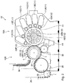
- the print layer 2 in the can body 1 is formed by a printer (offset printer) 10 shown in Fig. 2 .
- the printer 10 has, as the main configuration, a print layer forming part 10A, and a can body supply discharge part 10B for supplying the can body 1 before print layer formation to the print layer forming part 10A, and discharging the can body 1 after print layer formation.
- the print layer forming part 10A has ink stations 11 (11A, 11B, 11C, 11D, 11E, and 11F) for supplying an ink, plate cylinders 12 (12A, 12B, 12C, 12D, 12E, and 12F) each for supporting a plate, and a blanket drum 14 for supporting a blanket 13 of an intermediate transfer body.
- the ink stations 11 (11A to 11F) include a mechanism (such as an inker roller) for supplying the stored ink to the plate supported by the plate cylinder 12, and are arranged in a plurality of number for each plate around the blanket drum 14.
- the plurality of ink stations 11 (11A to 11F) may respectively supply inks of different colors, and some of them may supply inks of the same color.
- the blanket drum 14 rotates around the rotation shaft 14A, thereby bringing a plurality of blankets 13 supported therearound into contact with a plurality of plates supported by respective plate cylinders 12 (12A to 12F) one after another.
- the plate 20 supported by the plate cylinder 12 comes in contact with the ink supply mechanism (foam roller 110) in the ink station 11. Accordingly, an ink adheres to the line drawing part (convex part) 200 of the plate 20.
- the plate 20 to which the ink has adhered comes in contact with the surface of the blanket 13 supported on the support part 14B of the blanket drum 14 by the rotation of the plate cylinder 12 and the blanket drum 14. As a result, the ink adhered to the line drawing part 200 of the plate 20 is transferred to the blanket 13 of an intermediate transfer body.
- the can body supply discharge part 10B includes a can shooter 30 for getting the can bodies 1 therein, and a mandrel turret 31 for holding the can bodies 1 supplied from the can shooter 30, and successively rotationally moving the can bodies 1 in the direction of the print layer forming part 10A. Further, a varnish coating part 32 for applying a transparent over varnish on the surface of each can body 1 to which the print layer has been transferred is attached to the mandrel turret 31. Each can body 1 coated with the over varnish is guided to the discharge path 34 through a transfer turret 33.
- the formation step of the print layer by such a printer 10 will be described.
- the plate cylinders 12A, 12B, 12C, and 12D in the printer 10 each support a plate having a line drawing part corresponding to the character, the pattern, and the like to be printed on the outer surface of the can body.
- Respective plates are provided corresponding to the ink stations 11A, 11B, 11C, and 11D. This causes an ink to adhere to the plates supported by respective plate cylinders 12A to 12D.
- the ink adhered to each plate is transferred to the blanket 13 of an intermediate transfer body for every plate.
- the plate cylinder 12F supports a plate having a line drawing part of an electronic watermark image.
- the line drawing part of the electronic watermark image is formed in the area other than the line drawing part of the plate having the line drawing part of, for example, the character or the pattern (negative space).
- the plate of the plate cylinder 12F is provided corresponding to the ink station 11F.
- the ink supplied by the ink station 11F adheres to the line drawing part of the electronic watermark image.
- the adhered ink is transferred to the blanket 13 of an intermediate transfer body.
- the plate cylinder 12E supports the plate having the line drawing part that renders the electronic watermark image difficult to be visually recognized.
- the plate is provided corresponding to the ink station 11E.
- the ink supplied by the ink station 11E adheres to the line drawing part that renders the electronic watermark image difficult to be visually recognized.
- the adhered ink is transferred to the blanket 13 of an intermediate transfer body.
- the arrangement of the ink stations 11 (11A to 11F) (or, the plate cylinders 12 (12A to 12F) corresponding thereto) is not limited to the shown example, and they may be arranged in any order.
- the plates of the line drawing parts of the electronic watermark image and the line drawing parts that renders the electronic watermark image difficult to be visually recognized may be provided in plurality, respectively.
- the ink stations and the plate cylinders corresponding to the plates are set.
- the number of the plates was four, but is not limited to the number.
- the line drawing part of the electronic watermark image and the line drawing part of a character, a pattern, and the like may be provided at one plate.
- Figs. 4 and 5 show the line drawing parts of respective plates supported by the plate cylinders 12 (12A to 12F).
- Fig. 4 shows the plates supported by the plate cylinders 12A to 12D, where Fig. 4 at (a) shows, for example, a plate 20A of a first color.
- the plate 20A has a line drawing part 200A of the character print part 2A.
- Fig. 4 at (b) shows, for example, a plate 20B of a second color.
- the plate 20B has the line drawing part 200B of the character print part 2B.
- Fig. 4 at (c) shows, for example, a plate 20C of a third color.
- the plate 20C has the line drawing part 200C of the pattern print part 2C.
- Fig. 4 at (d) shows a plate 20D of a fourth color.
- the plate 20D has the line drawing part 200D of the character print part 2D.
- Fig. 5 shows the line drawing parts of respective plates supported by the plate cylinders 12E and 12F.
- Fig. 5 at (a) shows the plate 20F supported by the plate cylinder 12F.
- the plate 20F has the line drawing part 200F of the electronic watermark image.
- the line drawing part 200F of the electronic watermark image is formed in the common area except for the line drawing part corresponding to the plates 20A to 20D shown in Fig. 4 at (a) to (d) .
- the line drawing part 200F of the electronic watermark image may be formed in the entire area except for the line drawing parts corresponding to the plates 20A to 20D, or may be formed in a part thereof.
- the line drawing part 200E of the electronic watermark image does not overlap the area of the line drawing parts in the plates 20A to 20D. This prevents the reduction of the clarity of display, the design, or the like of the line drawing parts in the plates 20A to 20D.
- the line drawing part 200E of the electronic watermark image may be formed in a part or the whole of, or further over and beyond the area of line drawing part in the plates 20A to 20D.
- the electronic watermark image is printed in an overlapping manner, or thereunder, so that the figure of the electronic watermark image may be good as a design.
- the figure of the electronic watermark image can be used as a marking such as a grid of dots or a mosaic as the design.
- an electronic watermark image can be placed as a character or the marking of the pattern itself.
- the following configuration is also acceptable.
- An electronic watermark image is placed in a partial or the whole area of the plates 20A to 20D, and the electronic watermark image is connected to the electronic watermark image placed in the surrounding negative space.
- the line drawing part 200E of the electronic watermark image may be displayed by expressing the electronic watermark figure (dots) in white, or coloring and expressing the figure portion (dots).
- Fig. 5 at (b) shows the plate 20E supported by the plate cylinder 12E.
- the plate 20E has the line drawing part 200E that renders the electronic watermark image difficult to be visually recognized.
- the line drawing part 200E that renders the electronic watermark image difficult to be visually recognized is formed in the area except for the line drawing part common to the plates 20A to 20D shown in Fig. 4 at (a) to (d) .
- the line drawing part 200E that renders the electronic watermark image difficult to be visually recognized matches the print area of the line drawing part 200F, but is not necessarily required to totally match therewith, and may partially match therewith.
- the blindfold layer 2G2 is printed by the line drawing part 200E of the plate 20E.
- the electronic watermark layer 2G1 including a read code is formed in the negative space except for the display area.
- read codes can be dispersed in a wide range of the outer surface of the container. This enables reading of the read codes without matching the reading range to a specific print section.
- the blindfold layer 2G2 is formed in the print area matching the electronic watermark layer 2G1. This can inhibit the display quality of the display area from being reduced by the electronic watermark image.
- the horizontal cross section (the cross section of the container in a standing position) of the to-be-printed portion of the container (can container) is in a circular shape.
- a shaping step of shaping into various shapes after the print step it is possible to form the final shape of the container into various shapes such as an ellipse or a rectangle.
- examples may be made of known expand shaping, bulge shaping, emboss shaping, necking shaping, or the like.
- the method for performing offset printing on a container having a soft material such as plastic as the material of the container, and having a three-dimensional structure is shown in Japanese Patent Application Publication No. 2008-044662 . This method can also be used.
Landscapes
- Engineering & Computer Science (AREA)
- Mechanical Engineering (AREA)
- Details Of Rigid Or Semi-Rigid Containers (AREA)
- Printing Methods (AREA)
Abstract
Description
- The present invention relates to a cylindrical container manufacturing method and a cylindrical container.
- A container having a character, a pattern, or the like printed on an outer surface thereof is generally known. The character, the pattern, or the like printed on such a container generally includes a read code such as a bar code or a two-dimensional code. The read code printed on the container is read by a reading device such as a camera or a scanner, whereby various information can be associated with containers individually (see the following PTL 1).
- [PTL 1]
Japanese Patent Application Publication No. 2006-248600 - For reading a read code printed on a container, it is necessary to match a read range to a site where a bar code or a two-dimensional code is printed. For this reason, at production sites or distribution management sites of containers, it becomes necessary to align the orientations of containers to a certain direction relative to the orientation of a set reading device, and this requires a complicated alignment operation of the containers. Further, when a consumer reads a bar code or a two-dimensional code by the camera function of a portable terminal, a problem of difficulty in finding out the print section of a bar code or a two-dimensional code arises.
- In order to address such a problem, it can be considered that read codes are printed on a plurality of sites on the outer surface of the container, or a read code is printed over a relatively larger area. However, this impairs the designability of the container, and makes the print of, for example, a trade name, which is to be displayed, difficult to be identified.
- An object of the present invention is to address such an issue. Namely, an object of the present invention is to enable easier reading of a read code without requiring matching a reading range to a specific print section, or without impairing designability of a container and clarity of a display print, and the like.
- In order to solve such problems, the present invention has the following features.
- A manufacturing method for a cylindrical container having a print layer formed on an outer surface thereof, the method including: with a plurality of plates having a line drawing part to be printed on the outer surface of the cylindrical container being provided, a step of allowing an ink to individually adhere to the plates, and transferring the ink, adhered to the plates, to an intermediate transfer body for each of the plates; and a step of transferring the ink, transferred to the intermediate transfer body, to the outer surface of the cylindrical container, wherein among the plates, at least one plate is a plate having a line drawing part of an electronic watermark image, and another plate is a plate having a line drawing part that renders the electronic watermark image difficult to be visually recognized, and a print area of the line drawing part that renders the electronic watermark image difficult to be visually recognized is matched with a part or entire print area of the electronic watermark image.
- A cylindrical container having a print layer on an outer surface thereof, wherein the print layer has a layer including the electronic watermark image printed thereon, and a blindfold layer that renders the electronic watermark image difficult to be visually recognized, and a print area of the blindfold layer matches a part or entirety of a print area of the electronic watermark image.
- The present invention has the foregoing features, and hence enables an electronic watermark image to be printed on the outer surface of a cylindrical container, and can render the printed electronic watermark image difficult to be visually recognized. As a result, it is possible to read the read code from the electronic watermark image with ease without matching the reading range to a specific print section. Further, in the print area of the electronic watermark image, a blindfold layer for rendering this difficult to be visually recognized is printed. For this reason, it becomes possible to read the read code from the electronic watermark image with ease without impairing the designability of the cylindrical container and the clarity of the display print.
-
- [
Fig. 1] Fig. 1 is an explanatory view showing one example of a cylindrical container in accordance with an embodiment of the present invention (Fig. 1 at (a) is a front view andFig. 1 at (b) is a back view). - [
Fig. 2] Fig. 2 is an explanatory view (an overall view) showing a printer for forming a print layer of the cylindrical container in accordance with an embodiment of the present invention. - [
Fig. 3] Fig. 3 is an explanatory view (a partial view) showing the printer for forming a print layer of the cylindrical container in accordance with an embodiment of the present invention. - [
Fig. 4] Fig. 4 is an explanatory view showing a plate (Fig. 4 at (a) is a plate for a first color,Fig. 4 at (b) is a plate for a second color,Fig. 4 at (c) is a plate for a third color, andFig. 4 at (d) is a plate for a fourth color) in the printer. - [
Fig. 5] Fig. 5 is an explanatory view showing a plate (Fig. 5 at (a) is a plate having a line drawing part of an electronic watermark image andFig. 5 at (b) is a plate having a line drawing part of a blindfold layer) in a printer. - Below, embodiments of the present invention will be described with reference to the accompanying drawings. In the following description, a description will be given by taking a can container as one of the cylindrical containers as an example. However, the cylindrical container in accordance with the embodiment of the present invention is not limited to a can container. Further, in the following embodiments, for the example of a can container, a description is given by taking a seamless can as an example. However, the can container may be a welded can, or the like. The cylindrical container in accordance with the embodiment of the present invention has no particular restriction on the material for the container, and, for example, a metal, plastic, glass, paper, and the like are also acceptable.
- Any shape of the cylindrical container is acceptable so long as a part thereof has a cylindrical shape. The overall shape of the container may be a bottle shape, a tube shape, or the like other than the cylindrical shape. Further, the ones in a cylindrical shape as the in-between shape, and shaped to have other shapes in the final shaping step are also included in the cylindrical containers in the present invention.
- As shown in
Fig. 1 , the can container is obtained by forming aprint layer 2 on the outer surface of a can body 1 including abottom part 1A, adrum part 1B, a can lid 1C, and the like. The can body 1 is a seamless can. Thebottom part 1A and thedrum part 1B are integrally formed by drawing/ironing processing from one sheet material. For the shown example, thecan lid 1C is seamed to, and is connected to the top of thedrum part 1B. The can body 1 shown is one example, and the shape of the can body 1 is not limited to the shown example. - The
print layer 2 of the can body 1 has a display area includingcharacter print parts pattern print part 2C, and the like, and a negative space 2G excluding the display area such as thecharacter print parts pattern print part 2C. Then, in the negative space 2G, a layer including an electronic watermark image printed therein (electronic watermark layer) 2G1, and a layer that renders the electronic watermark image difficult to be visually recognized (blindfold layer) 2G2 are printed. Herein, the blindfold layer 2G2 may be a layer formed on the electronic watermark layer 2G1, or a layer formed under the electronic watermark layer 2G1. - Further, the blindfold layer 2G2 may be formed in the entire area of the electronic watermark layer 2G1, or may be formed in a part thereof. Further, the blindfold layer 2G2 may be formed over and beyond the area of the electronic watermark layer 2G1. Further, herein, the electronic watermark image is printed in areas (negative space) other than the display area of a character, a pattern, and the like. In the color, the pattern, and the character used in a wide range in a plan view of the can front, an electronic watermark image may be placed. For example, in the case of the design such that a marking is repeatedly arranged along the entire circumference of the container, an electronic watermark image is placed at the repeated marking part. This enables reading of the read code from anywhere.
- The electronic watermark image includes, for example, watermark information including a read code embedded therein by undergoing two-dimensional pattern modulation, and is read by a reading device, thereby enabling acquisition of electronic data including various information.
- The
print layer 2 in the can body 1 is formed by a printer (offset printer) 10 shown inFig. 2 . Theprinter 10 has, as the main configuration, a printlayer forming part 10A, and a can bodysupply discharge part 10B for supplying the can body 1 before print layer formation to the printlayer forming part 10A, and discharging the can body 1 after print layer formation. - The print
layer forming part 10A has ink stations 11 (11A, 11B, 11C, 11D, 11E, and 11F) for supplying an ink, plate cylinders 12 (12A, 12B, 12C, 12D, 12E, and 12F) each for supporting a plate, and ablanket drum 14 for supporting ablanket 13 of an intermediate transfer body. The ink stations 11 (11A to 11F) include a mechanism (such as an inker roller) for supplying the stored ink to the plate supported by theplate cylinder 12, and are arranged in a plurality of number for each plate around theblanket drum 14. The plurality of ink stations 11 (11A to 11F) may respectively supply inks of different colors, and some of them may supply inks of the same color. - The
blanket drum 14 rotates around therotation shaft 14A, thereby bringing a plurality ofblankets 13 supported therearound into contact with a plurality of plates supported by respective plate cylinders 12 (12A to 12F) one after another. - As shown in
Fig. 3 , theplate 20 supported by theplate cylinder 12 comes in contact with the ink supply mechanism (foam roller 110) in theink station 11. Accordingly, an ink adheres to the line drawing part (convex part) 200 of theplate 20. Theplate 20 to which the ink has adhered comes in contact with the surface of theblanket 13 supported on thesupport part 14B of theblanket drum 14 by the rotation of theplate cylinder 12 and theblanket drum 14. As a result, the ink adhered to theline drawing part 200 of theplate 20 is transferred to theblanket 13 of an intermediate transfer body. - The can body supply
discharge part 10B includes acan shooter 30 for getting the can bodies 1 therein, and amandrel turret 31 for holding the can bodies 1 supplied from thecan shooter 30, and successively rotationally moving the can bodies 1 in the direction of the printlayer forming part 10A. Further, avarnish coating part 32 for applying a transparent over varnish on the surface of each can body 1 to which the print layer has been transferred is attached to themandrel turret 31. Each can body 1 coated with the over varnish is guided to thedischarge path 34 through atransfer turret 33. - The formation step of the print layer by such a
printer 10 will be described. Theplate cylinders printer 10 each support a plate having a line drawing part corresponding to the character, the pattern, and the like to be printed on the outer surface of the can body. Respective plates are provided corresponding to theink stations respective plate cylinders 12A to 12D. The ink adhered to each plate is transferred to theblanket 13 of an intermediate transfer body for every plate. - In contrast, the
plate cylinder 12F supports a plate having a line drawing part of an electronic watermark image. The line drawing part of the electronic watermark image is formed in the area other than the line drawing part of the plate having the line drawing part of, for example, the character or the pattern (negative space). The plate of theplate cylinder 12F is provided corresponding to theink station 11F. The ink supplied by theink station 11F adheres to the line drawing part of the electronic watermark image. The adhered ink is transferred to theblanket 13 of an intermediate transfer body. - Further, the
plate cylinder 12E supports the plate having the line drawing part that renders the electronic watermark image difficult to be visually recognized. The plate is provided corresponding to theink station 11E. The ink supplied by theink station 11E adheres to the line drawing part that renders the electronic watermark image difficult to be visually recognized. The adhered ink is transferred to theblanket 13 of an intermediate transfer body. - Then, all the inks transferred to one
blanket 13 are transferred in accordance with the rotation of theblanket drum 14 and themandrel turret 31 having the can bodies 1 held thereon from theblanket 13 to the outer surface of each can body 1. As a result, theprint layer 2 is formed on the can body 1. Subsequently, each can body 1 having theprint layer 2 formed thereon is moved by the rotation of themandrel turret 31. Thevarnish coating part 32 attached to themandrel turret 31 applies an over varnish onto theprint layer 2. For the can body 1 thus undergoing printing, reading of the electronic watermark information was possible by the camera of a portable terminal. - Incidentally, in the foregoing description, the arrangement of the ink stations 11 (11A to 11F) (or, the plate cylinders 12 (12A to 12F) corresponding thereto) is not limited to the shown example, and they may be arranged in any order. Further, the plates of the line drawing parts of the electronic watermark image and the line drawing parts that renders the electronic watermark image difficult to be visually recognized may be provided in plurality, respectively. In that case, the ink stations and the plate cylinders corresponding to the plates are set. Also for the plate having the line drawing part corresponding to the character, the pattern, and the like, in the previous description, the number of the plates was four, but is not limited to the number. Further, when the line drawing part of the electronic watermark image and the line drawing part of a character, a pattern, and the like have the ink in the same color, the line drawing part of the electronic watermark image and the line drawing part of a character, a pattern, or the like may be provided at one plate.
-
Figs. 4 and5 show the line drawing parts of respective plates supported by the plate cylinders 12 (12A to 12F).Fig. 4 shows the plates supported by theplate cylinders 12A to 12D, whereFig. 4 at (a) shows, for example, aplate 20A of a first color. Herein, theplate 20A has aline drawing part 200A of thecharacter print part 2A.Fig. 4 at (b) shows, for example, aplate 20B of a second color. Herein, theplate 20B has theline drawing part 200B of thecharacter print part 2B.Fig. 4 at (c) shows, for example, aplate 20C of a third color. Herein, theplate 20C has theline drawing part 200C of thepattern print part 2C.Fig. 4 at (d) shows aplate 20D of a fourth color. Herein, theplate 20D has theline drawing part 200D of thecharacter print part 2D. -
Fig. 5 shows the line drawing parts of respective plates supported by theplate cylinders Fig. 5 at (a) shows theplate 20F supported by theplate cylinder 12F. Theplate 20F has theline drawing part 200F of the electronic watermark image. Theline drawing part 200F of the electronic watermark image is formed in the common area except for the line drawing part corresponding to theplates 20A to 20D shown inFig. 4 at (a) to (d) . Herein, theline drawing part 200F of the electronic watermark image may be formed in the entire area except for the line drawing parts corresponding to theplates 20A to 20D, or may be formed in a part thereof. As the effects thereof, theline drawing part 200E of the electronic watermark image does not overlap the area of the line drawing parts in theplates 20A to 20D. This prevents the reduction of the clarity of display, the design, or the like of the line drawing parts in theplates 20A to 20D. - On the other hand, the
line drawing part 200E of the electronic watermark image may be formed in a part or the whole of, or further over and beyond the area of line drawing part in theplates 20A to 20D. The reason for this is as follows. Also in the print area showing a character or a pattern such as line drawing part in theplates 20A to 20D, the electronic watermark image is printed in an overlapping manner, or thereunder, so that the figure of the electronic watermark image may be good as a design. For example, the figure of the electronic watermark image can be used as a marking such as a grid of dots or a mosaic as the design. For this reason, an electronic watermark image can be placed as a character or the marking of the pattern itself. For the same reason, the following configuration is also acceptable. An electronic watermark image is placed in a partial or the whole area of theplates 20A to 20D, and the electronic watermark image is connected to the electronic watermark image placed in the surrounding negative space. - Up to this point, in any case, the effects of the present invention of allowing easy reading of a read code from the electronic watermark image without matching the reading range of the electronic watermark to a specific print section, and preventing the reduction of the designability and the clarity of the display print of a can container can be exerted. Incidentally, the
line drawing part 200E of the electronic watermark image may be displayed by expressing the electronic watermark figure (dots) in white, or coloring and expressing the figure portion (dots). -
Fig. 5 at (b) shows theplate 20E supported by theplate cylinder 12E. Theplate 20E has theline drawing part 200E that renders the electronic watermark image difficult to be visually recognized. Similarly to theline drawing part 200F, theline drawing part 200E that renders the electronic watermark image difficult to be visually recognized is formed in the area except for the line drawing part common to theplates 20A to 20D shown inFig. 4 at (a) to (d) . Theline drawing part 200E that renders the electronic watermark image difficult to be visually recognized matches the print area of theline drawing part 200F, but is not necessarily required to totally match therewith, and may partially match therewith. The blindfold layer 2G2 is printed by theline drawing part 200E of theplate 20E. - With such a container or manufacturing method for a container, even when the
print layer 2 printed on the outer surface of the container is a print layer including an electronic watermark image, it becomes possible to clearly display a display area including acharacter print parts pattern print part 2C, and the like. - Further, the electronic watermark layer 2G1 including a read code is formed in the negative space except for the display area. As a result, read codes can be dispersed in a wide range of the outer surface of the container. This enables reading of the read codes without matching the reading range to a specific print section. Further, the blindfold layer 2G2 is formed in the print area matching the electronic watermark layer 2G1. This can inhibit the display quality of the display area from being reduced by the electronic watermark image.
- Incidentally, in the foregoing description, the case was shown where the horizontal cross section (the cross section of the container in a standing position) of the to-be-printed portion of the container (can container) is in a circular shape. By providing a shaping step of shaping into various shapes after the print step, it is possible to form the final shape of the container into various shapes such as an ellipse or a rectangle. As the shaping step, examples may be made of known expand shaping, bulge shaping, emboss shaping, necking shaping, or the like.
- Incidentally, the method for performing offset printing on a container having a soft material such as plastic as the material of the container, and having a three-dimensional structure is shown in
Japanese Patent Application Publication No. 2008-044662 -
- 1
- Can body
- 2
- Print layer
- 2A, 2B, 2D
- Character print part
- 2C
- Pattern print part
- 2G
- Negative space
- 2G1
- Electronic watermark layer
- 2G2
- Blindfold layer
- 10
- Printer
- 20, 20A to 20F
- Plate
- 200, 200A to 200F
- Line drawing part
Claims (10)
- A manufacturing method for a cylindrical container having a print layer formed on an outer surface thereof,
the method comprising:with a plurality of plates having a line drawing part to be printed on the outer surface of the cylindrical container being provided,a step of allowing an ink to individually adhere to the plates, and transferring the ink, adhered to the plates, to an intermediate transfer body for each of the plates; anda step of transferring the ink, transferred to the intermediate transfer body, to the outer surface of the cylindrical container,wherein among the plates, at least one plate is a plate having a line drawing part of an electronic watermark image, and another plate is a plate having a line drawing part that renders the electronic watermark image difficult to be visually recognized, anda print area of the line drawing part that renders the electronic watermark image difficult to be visually recognized is matched with a part or entire print area of the electronic watermark image. - The manufacturing method for a cylindrical container according to claim 1, wherein the line drawing part of the electronic watermark image and the line drawing part that renders the electronic watermark image difficult to be visually recognized are formed in an area except for a line drawing part corresponding to the other plate.
- The manufacturing method for a cylindrical container according to claim 1, wherein the line drawing part of the electronic watermark image and the line drawing part that renders the electronic watermark image difficult to be visually recognized are formed in a partial or entire area of a line drawing part corresponding to the other plate.
- The manufacturing method for a cylindrical container according to claim 2 or 3, wherein the line drawing part of the electronic watermark image is formed in a part or entirety of a negative space.
- The manufacturing method for a cylindrical container according to claims 1 to 4, wherein the cylindrical container is a metallic can.
- A cylindrical container having a print layer on an outer surface thereof, wherein
the print layer has
an electronic watermark layer including an electronic watermark image printed thereon, and a blindfold layer that renders the electronic watermark image difficult to be visually recognized, and
a print area of the blindfold layer matches a part or entirety of a print area of the electronic watermark layer. - The cylindrical container according to claim 6, wherein the print layer includes the electronic watermark layer, the blindfold layer, and an image layer other than the electronic watermark layer and the blindfold layer, and wherein a print area of the other image layer and a print area of the electronic watermark layer do not overlap each other.
- The cylindrical container according to claim 6, wherein the print layer includes the electronic watermark layer, the blindfold layer, and an image layer other than the electronic watermark layer and the blindfold layer, and wherein a print area of the electronic watermark layer partially or entirely overlaps a print area of the other image layer.
- The cylindrical container according to claim 7 or 8, wherein the electronic watermark image is printed in a negative space of an image to be printed in the cylindrical container.
- The cylindrical container according to any one of claims 6 to 9, wherein the cylindrical container is a metallic can.
Applications Claiming Priority (2)
| Application Number | Priority Date | Filing Date | Title |
|---|---|---|---|
| JP2018180797A JP7406690B2 (en) | 2018-09-26 | 2018-09-26 | Method for manufacturing a cylindrical container and cylindrical container |
| PCT/JP2019/037474 WO2020067099A1 (en) | 2018-09-26 | 2019-09-25 | Method for manufacturing cylindrical container, and cylindrical container |
Publications (2)
| Publication Number | Publication Date |
|---|---|
| EP3858616A1 true EP3858616A1 (en) | 2021-08-04 |
| EP3858616A4 EP3858616A4 (en) | 2022-08-17 |
Family
ID=69952886
Family Applications (1)
| Application Number | Title | Priority Date | Filing Date |
|---|---|---|---|
| EP19864958.4A Withdrawn EP3858616A4 (en) | 2018-09-26 | 2019-09-25 | PROCESS FOR MAKING A CYLINDRICAL CONTAINER AND CYLINDRICAL CONTAINERS |
Country Status (4)
| Country | Link |
|---|---|
| US (1) | US11718116B2 (en) |
| EP (1) | EP3858616A4 (en) |
| JP (1) | JP7406690B2 (en) |
| WO (1) | WO2020067099A1 (en) |
Cited By (1)
| Publication number | Priority date | Publication date | Assignee | Title |
|---|---|---|---|---|
| US12662279B2 (en) | 2021-02-26 | 2026-06-23 | Ball Corporation | Container with mark or markings for tracking and tracing |
Families Citing this family (1)
| Publication number | Priority date | Publication date | Assignee | Title |
|---|---|---|---|---|
| JP7409747B2 (en) * | 2019-04-08 | 2024-01-09 | 大阪シーリング印刷株式会社 | Packaging material for transparent containers |
Family Cites Families (17)
| Publication number | Priority date | Publication date | Assignee | Title |
|---|---|---|---|---|
| JP3674500B2 (en) | 2000-11-24 | 2005-07-20 | 東洋製罐株式会社 | Method and apparatus for offset printing on cylindrical articles |
| US7243795B2 (en) * | 2004-03-30 | 2007-07-17 | Robert Gold | Identification system for individual containers |
| JP4826108B2 (en) | 2005-03-14 | 2011-11-30 | 東洋製罐株式会社 | Container with cap |
| US20070164559A1 (en) * | 2006-01-17 | 2007-07-19 | Kozdras Michael W | Instant lottery ticket and method |
| JP4965190B2 (en) | 2006-08-21 | 2012-07-04 | 武内プレス工業株式会社 | Tube container and printing method of the tube container |
| JP5218744B2 (en) | 2008-03-28 | 2013-06-26 | 東洋製罐株式会社 | Food container with identification code and method for forming identification code of food container |
| BR112013003196A2 (en) * | 2010-08-11 | 2017-06-13 | Securency Int Pty Ltd | optically variable device |
| JP5724285B2 (en) * | 2010-10-19 | 2015-05-27 | 東洋製罐株式会社 | Printing seamless can and manufacturing method thereof |
| US8867782B2 (en) | 2012-06-19 | 2014-10-21 | Eastman Kodak Company | Spectral edge marking for steganography or watermarking |
| DE102012105571B4 (en) * | 2012-06-26 | 2017-03-09 | Ovd Kinegram Ag | Decorative element as well as security document with a decorative element |
| WO2014008544A1 (en) * | 2012-07-10 | 2014-01-16 | Amcor Limited | An apparatus and process |
| WO2014019163A1 (en) * | 2012-08-01 | 2014-02-06 | Sicpa Holding Sa | Optically variable security threads and stripes |
| JP2014104637A (en) | 2012-11-27 | 2014-06-09 | Dainippon Printing Co Ltd | Forgery prevention printed matter |
| WO2015036045A1 (en) * | 2013-09-13 | 2015-03-19 | CSEM Centre Suisse d'Electronique et de Microtechnique SA - Recherche et Développement | Lightguide tamper seal |
| WO2015093405A1 (en) * | 2013-12-17 | 2015-06-25 | 東洋製罐株式会社 | Printed film for vessel, and method for manufacturing same |
| US10065441B2 (en) | 2015-09-01 | 2018-09-04 | Digimarc Corporation | Counterfeiting detection using machine readable indicia |
| JP6696641B2 (en) | 2016-06-24 | 2020-05-20 | アイマー・プランニング株式会社 | Printing misalignment correction method in printing apparatus |
-
2018
- 2018-09-26 JP JP2018180797A patent/JP7406690B2/en active Active
-
2019
- 2019-09-25 EP EP19864958.4A patent/EP3858616A4/en not_active Withdrawn
- 2019-09-25 US US17/279,671 patent/US11718116B2/en active Active
- 2019-09-25 WO PCT/JP2019/037474 patent/WO2020067099A1/en not_active Ceased
Cited By (1)
| Publication number | Priority date | Publication date | Assignee | Title |
|---|---|---|---|---|
| US12662279B2 (en) | 2021-02-26 | 2026-06-23 | Ball Corporation | Container with mark or markings for tracking and tracing |
Also Published As
| Publication number | Publication date |
|---|---|
| JP2020049761A (en) | 2020-04-02 |
| WO2020067099A1 (en) | 2020-04-02 |
| US20220032670A1 (en) | 2022-02-03 |
| EP3858616A4 (en) | 2022-08-17 |
| US11718116B2 (en) | 2023-08-08 |
| JP7406690B2 (en) | 2023-12-28 |
Similar Documents
| Publication | Publication Date | Title |
|---|---|---|
| US8365658B2 (en) | Method for ornamenting container, ornamented container manufactured by the method, and mandrel, drum, and ornamenting apparatus used for the method | |
| CN104640706B (en) | Apparatus and method for printing image | |
| CN106029381B (en) | Polychrome letterpress with marking roller and additional printing element | |
| US20210001655A1 (en) | Container, method for manufacturing container, and printing apparatus | |
| JPH09510410A (en) | Multicolor printing machine | |
| US11718116B2 (en) | Method for manufacturing cylindrical container, and cylindrical container | |
| JP7422814B2 (en) | Beverage can manufacturing method, beverage can, and beverage can | |
| WO2018013677A1 (en) | Apparatus and method of screen decorating metallic containers | |
| CN101547794A (en) | Method for printing containers along the perimeter | |
| JPH0939366A (en) | Multicolor printing method for curved objects | |
| JP7419796B2 (en) | Substrate manufacturing method and container | |
| US8449103B2 (en) | Method and apparatus for high-speed multicolor inkjet printing | |
| JP2001138484A (en) | Varnish coating equipment for 2-piece cans | |
| JP4941655B2 (en) | Printing press and printing press blanket | |
| CN206999863U (en) | Improve the device of advertising and printing quality | |
| JP2006224585A (en) | Seamless can body | |
| JP2002113936A (en) | Sheet-fed gravure printing method, gravure sheet-fed printing machine, and cylinder for gravure printing | |
| US20060243147A1 (en) | Offset printing press | |
| JP2006224584A (en) | Seamless can body | |
| WO2008017589A1 (en) | Method and apparatus for printing sheet metal |
Legal Events
| Date | Code | Title | Description |
|---|---|---|---|
| STAA | Information on the status of an ep patent application or granted ep patent |
Free format text: STATUS: THE INTERNATIONAL PUBLICATION HAS BEEN MADE |
|
| PUAI | Public reference made under article 153(3) epc to a published international application that has entered the european phase |
Free format text: ORIGINAL CODE: 0009012 |
|
| STAA | Information on the status of an ep patent application or granted ep patent |
Free format text: STATUS: REQUEST FOR EXAMINATION WAS MADE |
|
| 17P | Request for examination filed |
Effective date: 20210423 |
|
| AK | Designated contracting states |
Kind code of ref document: A1 Designated state(s): AL AT BE BG CH CY CZ DE DK EE ES FI FR GB GR HR HU IE IS IT LI LT LU LV MC MK MT NL NO PL PT RO RS SE SI SK SM TR |
|
| DAV | Request for validation of the european patent (deleted) | ||
| DAX | Request for extension of the european patent (deleted) | ||
| A4 | Supplementary search report drawn up and despatched |
Effective date: 20220714 |
|
| RIC1 | Information provided on ipc code assigned before grant |
Ipc: B41M 1/40 20060101ALI20220708BHEP Ipc: B41M 3/10 20060101ALI20220708BHEP Ipc: B41M 3/14 20060101ALI20220708BHEP Ipc: B41M 1/28 20060101ALI20220708BHEP Ipc: B41F 17/22 20060101AFI20220708BHEP |
|
| STAA | Information on the status of an ep patent application or granted ep patent |
Free format text: STATUS: THE APPLICATION HAS BEEN WITHDRAWN |
|
| 18W | Application withdrawn |
Effective date: 20250519 |