EP3858493A1 - Coating apparatus - Google Patents
Coating apparatus Download PDFInfo
- Publication number
- EP3858493A1 EP3858493A1 EP19883256.0A EP19883256A EP3858493A1 EP 3858493 A1 EP3858493 A1 EP 3858493A1 EP 19883256 A EP19883256 A EP 19883256A EP 3858493 A1 EP3858493 A1 EP 3858493A1
- Authority
- EP
- European Patent Office
- Prior art keywords
- coating
- dispenser
- coating surface
- tilt
- respect
- Prior art date
- Legal status (The legal status is an assumption and is not a legal conclusion. Google has not performed a legal analysis and makes no representation as to the accuracy of the status listed.)
- Withdrawn
Links
- 239000011248 coating agent Substances 0.000 title claims abstract description 210
- 238000000576 coating method Methods 0.000 title claims abstract description 210
- 238000001514 detection method Methods 0.000 claims abstract description 25
- 239000007788 liquid Substances 0.000 claims abstract description 22
- 238000006073 displacement reaction Methods 0.000 claims abstract description 20
- 238000007599 discharging Methods 0.000 claims abstract description 5
- 230000002093 peripheral effect Effects 0.000 claims description 10
- 230000000694 effects Effects 0.000 description 2
- 238000012986 modification Methods 0.000 description 2
- 230000004048 modification Effects 0.000 description 2
- LFQSCWFLJHTTHZ-UHFFFAOYSA-N Ethanol Chemical compound CCO LFQSCWFLJHTTHZ-UHFFFAOYSA-N 0.000 description 1
- 239000006071 cream Substances 0.000 description 1
- 230000007423 decrease Effects 0.000 description 1
- 238000010586 diagram Methods 0.000 description 1
- 239000011344 liquid material Substances 0.000 description 1
- 229910000679 solder Inorganic materials 0.000 description 1
Images


Classifications
-
- B—PERFORMING OPERATIONS; TRANSPORTING
- B05—SPRAYING OR ATOMISING IN GENERAL; APPLYING FLUENT MATERIALS TO SURFACES, IN GENERAL
- B05C—APPARATUS FOR APPLYING FLUENT MATERIALS TO SURFACES, IN GENERAL
- B05C11/00—Component parts, details or accessories not specifically provided for in groups B05C1/00 - B05C9/00
- B05C11/10—Storage, supply or control of liquid or other fluent material; Recovery of excess liquid or other fluent material
- B05C11/1002—Means for controlling supply, i.e. flow or pressure, of liquid or other fluent material to the applying apparatus, e.g. valves
- B05C11/1015—Means for controlling supply, i.e. flow or pressure, of liquid or other fluent material to the applying apparatus, e.g. valves responsive to a conditions of ambient medium or target, e.g. humidity, temperature ; responsive to position or movement of the coating head relative to the target
- B05C11/1018—Means for controlling supply, i.e. flow or pressure, of liquid or other fluent material to the applying apparatus, e.g. valves responsive to a conditions of ambient medium or target, e.g. humidity, temperature ; responsive to position or movement of the coating head relative to the target responsive to distance of target
-
- B—PERFORMING OPERATIONS; TRANSPORTING
- B05—SPRAYING OR ATOMISING IN GENERAL; APPLYING FLUENT MATERIALS TO SURFACES, IN GENERAL
- B05C—APPARATUS FOR APPLYING FLUENT MATERIALS TO SURFACES, IN GENERAL
- B05C11/00—Component parts, details or accessories not specifically provided for in groups B05C1/00 - B05C9/00
- B05C11/10—Storage, supply or control of liquid or other fluent material; Recovery of excess liquid or other fluent material
-
- B—PERFORMING OPERATIONS; TRANSPORTING
- B05—SPRAYING OR ATOMISING IN GENERAL; APPLYING FLUENT MATERIALS TO SURFACES, IN GENERAL
- B05C—APPARATUS FOR APPLYING FLUENT MATERIALS TO SURFACES, IN GENERAL
- B05C5/00—Apparatus in which liquid or other fluent material is projected, poured or allowed to flow on to the surface of the work
- B05C5/02—Apparatus in which liquid or other fluent material is projected, poured or allowed to flow on to the surface of the work the liquid or other fluent material being discharged through an outlet orifice by pressure, e.g. from an outlet device in contact or almost in contact, with the work
- B05C5/0204—Apparatus in which liquid or other fluent material is projected, poured or allowed to flow on to the surface of the work the liquid or other fluent material being discharged through an outlet orifice by pressure, e.g. from an outlet device in contact or almost in contact, with the work for applying liquid or other fluent material to the edges of essentially flat articles
-
- B—PERFORMING OPERATIONS; TRANSPORTING
- B05—SPRAYING OR ATOMISING IN GENERAL; APPLYING FLUENT MATERIALS TO SURFACES, IN GENERAL
- B05C—APPARATUS FOR APPLYING FLUENT MATERIALS TO SURFACES, IN GENERAL
- B05C5/00—Apparatus in which liquid or other fluent material is projected, poured or allowed to flow on to the surface of the work
- B05C5/02—Apparatus in which liquid or other fluent material is projected, poured or allowed to flow on to the surface of the work the liquid or other fluent material being discharged through an outlet orifice by pressure, e.g. from an outlet device in contact or almost in contact, with the work
- B05C5/0208—Apparatus in which liquid or other fluent material is projected, poured or allowed to flow on to the surface of the work the liquid or other fluent material being discharged through an outlet orifice by pressure, e.g. from an outlet device in contact or almost in contact, with the work for applying liquid or other fluent material to separate articles
- B05C5/0212—Apparatus in which liquid or other fluent material is projected, poured or allowed to flow on to the surface of the work the liquid or other fluent material being discharged through an outlet orifice by pressure, e.g. from an outlet device in contact or almost in contact, with the work for applying liquid or other fluent material to separate articles only at particular parts of the articles
- B05C5/0216—Apparatus in which liquid or other fluent material is projected, poured or allowed to flow on to the surface of the work the liquid or other fluent material being discharged through an outlet orifice by pressure, e.g. from an outlet device in contact or almost in contact, with the work for applying liquid or other fluent material to separate articles only at particular parts of the articles by relative movement of article and outlet according to a predetermined path
Definitions
- the present disclosure relates to a coating apparatus.
- PTL 1 discloses a sealer coating apparatus for coating a peripheral edge portion of a windshield of an automobile with a sealer.
- the windshield is held by a work holding unit extending in the vertical direction from a belt conveyor moving along the horizontal plane so as not to be tilted with respect to the horizontal plane.
- a positional deviation of the windshield in such a sealer coating apparatus is corrected, the rotational deviation of the windshield on the horizontal plane or the vertical deviation of the windshield usually is taken into consideration.
- tilting of the windshield with respect to the horizontal plane is not considered.
- An object of the present disclosure is to provide a coating apparatus capable of accurately applying liquid to a predetermined position on a coating surface even if the coating surface is tilted with respect to the horizontal plane.
- a coating apparatus as an example of the present disclosure including:
- a tilt of the coating surface with respect to the reference plane extending in a direction intersecting the vertical direction is detected based on the distance detected by the displacement sensor, and the coating path is corrected based on the tilt of the detected coating surface.
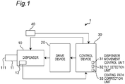
- a coating apparatus 1 includes a dispenser 10, a drive device 20 capable of driving the dispenser 10, and a control device 30 that controls the dispenser 10 and the drive device 20.
- the dispenser 10 includes a nozzle 11 and a displacement sensor 12.
- the nozzle 11 include a discharge port 111 capable of discharging liquid from the vertical direction Z to a coating region 102 provided on an outer peripheral edge of a coating surface 101 of an object 100 to be coated.
- the displacement sensor 12 detects a distance D in the vertical direction Z between the discharge port 111 and the coating region 102 of the coating surface 101.
- Figs. 2 and 3 illustrate a plate-shaped object 100 to be coated on which the substantially rectangular coating surface 101 is arranged along the horizontal plane XY.
- the dispenser 10 is, for example, an air pulse type dispenser that can use a liquid material having any desired viscosity (Pa ⁇ s) (for example, alcohol having a viscosity less than 0.001 or cream solder having a viscosity exceeding 100) as the liquid discharged from the discharge port 111.
- a liquid material having any desired viscosity for example, alcohol having a viscosity less than 0.001 or cream solder having a viscosity exceeding 100
- the drive device 20 is, for example, a robot, and configured to be movable in the horizontal directions X and Y (see Fig. 2 ) and the vertical direction Z (see Fig. 3 ) by holding the dispenser 10 in a state where liquid can be discharged in the vertical direction Z from the discharge port 111.
- the control device 30 includes a CPU that performs calculation and the like, a storage medium such as a ROM, RAM, and the like for storing a program or data necessary for controlling the dispenser 10 and the drive device 20, and an interface unit that performs input and output of a signal to and from an external unit (not shown).
- the control device 30 includes a dispenser movement control unit 31, a tilt detection unit 32, and a coating path correction unit 33.
- the dispenser movement control unit 31, the tilt detection unit 32, and the coating path correction unit 33 are functions realized by the CPU of the control device 30 executing a predetermined program.
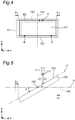
- the dispenser movement control unit 31 moves the dispenser 10 along a predetermined coating path R1 for each of the object 100 to be coated. Further, when the coating path R1 is corrected by the coating path correction unit 33 as described later, the dispenser movement control unit 31 moves the dispenser 10 along a corrected coating path R2 (see Fig. 4 ).
- the tilt detection unit 32 detects a tilt ⁇ of the coating surface 101 with respect to a reference plane P (a horizontal plane in the present embodiment) extending in a direction intersecting the vertical direction Z (see Fig. 5 ) based on the distance D detected by the displacement sensor 12. Specifically, the tilt detection unit 32 detects the tilt ⁇ around a rotation axis 110 extending in the X direction on the coating surface 101 based on a reference distance D1 and a distance D2.
- the reference distance D1 is detected in advance in at least three preset locations (for example, points A, B, and C shown in Fig. 2 ) that are at the outer peripheral edge of the coating surface 101 of the reference object 100 to be coated and are on the coating path R1.
- the distance D2 is detected in at least three preset locations (that is, points A, B, and C shown in Fig. 4 ) that are at the outer peripheral edge of the coating surface 101 of the object 100 to be coated and are on the coating path R1.
- the object 100 to be coated shown in Figs. 2 and 3 (that is, the object 100 to be coated in which the coating surface 101 is horizontally arranged) is used as the reference object 100 to be coated.
- the reference distance D1 and the distance D2 are the distance D detected in a state where the discharge port 111 is at the same position with respect to the reference plane P in the vertical direction Z.
- the reference plane P is not limited to the horizontal plane, and is set according to the position and attitude of the reference object 100 to be coated.
- the coating path correction unit 33 corrects the coating path R1 based on the tilt ⁇ of the coating surface 101 detected by the tilt detection unit 32. For example, when the coating surface 101 is tilted by an angle ⁇ around the rotation axis 110, the coating surface 101 viewed from the vertical direction Z, which is the liquid discharge direction, becomes smaller by ⁇ L ⁇ 2 in the Y direction, as shown in Figs. 4 and 5 . Thus, the coating path correction unit 33 corrects a length of the coating path R1 in the Y direction according to the tilt ⁇ of the coating surface 101 detected by the tilt detection unit 32 to create the coating path R2.
- the coating apparatus 1 includes an image sensor 40 that detects a position and attitude of the object 100 to be coated.
- the control device 30 sets the coating path R1 based on the position and attitude of the reference object 100 to be coated detected by the image sensor 40.
- the dispenser movement control unit 31 moves the dispenser 10 along the coating path R1 preset based on the position and attitude of the reference object 100 to be coated detected by the image sensor 40. Then, the displacement sensor 12 detects the distance D2 in the vertical direction Z between the discharge port 111 and the coating surface 101 in at least three preset locations that are at the outer peripheral edge of the coating surface 101 and are on the coating path R1 (Step S1).
- the tilt detection unit 32 detects the tilt ⁇ of the coating surface 101 with respect to the reference plane P based on the detected distance D2 and the preset reference distance D1 (Step S2). Then, the control device 30 determines whether the coating surface 101 is tilted with respect to the reference plane P based on whether the tilt detection unit 32 detects the tilt ⁇ of the coating surface 101 with respect to the reference plane P (Step S3).
- the coating path correction unit 33 corrects the coating path R1 based on the detected tilt ⁇ of the coating surface 101 with respect to the reference plane P (Step S4). Then, the dispenser movement control unit 31 moves the dispenser 10 along the corrected coating path R2 (Step S5). When it is determined that the coating surface 101 is not tilted with respect to the reference plane P, the dispenser movement control unit 31 moves the dispenser 10 along the coating path R1 (Step S6).
- Steps S6 and S7 when the dispenser 10 is moving on the coating path R1 and R2, the control device 30 controls the dispenser 10 to discharge liquid from the discharge port 111 of the nozzle 11 toward the coating region 102. Then, when the application of the liquid to the coating region 102 is completed, the coating processing is completed.
- the tilt ⁇ of the coating surface 101 with respect to the reference plane P extending in the direction intersecting the vertical direction Z is detected based on the distance D detected by the displacement sensor 12, and the coating path R1 is corrected based on the tilt ⁇ of the detected coating surface 101.
- Such a configuration makes it possible to realize the coating apparatus 1 capable of accurately applying liquid to a predetermined position (that is, the coating region 102) of the coating surface 101 even if, for example, the object 100 to be coated is not held and the coating surface 101 is tilted with respect to the reference plane.
- the tilt detection unit 32 detects the tilt of the coating surface 101 based on the distance D1 and D2 detected in at least three locations that are at the outer peripheral edge of the coating surface 101 and are on the coating path R1 and R2. With such a configuration, the tilt ⁇ of the coating surface 101 with respect to the reference plane P can be detected more accurately.
- the tilt detection unit 32 may detect the tilt of the coating surface 101 based on the distance D1 and D2 detected in two locations on the coating path R1 and R2.
- the locations on the coating path R1 and R2 in which the distance D1 and D2 is detected by the tilt detection unit 32 may not be at the outer peripheral edge of the coating surface 101.
- the coating surface 101 is not limited to a substantially rectangular shape, and may have any desired shape.
- the coating region 102 is not limited to the outer peripheral edge of the coating surface 101, and may be set to any other area.
- the dispenser movement control unit 31 may be configured to move the dispenser 10, when the coating surface 101 is tilted with respect to the reference plane P, at a speed different from that when the coating surface 101 is not tilted with respect to the reference plane P.
- the dispenser 10 is moved at a speed lower that when the coating surface 101 is horizontal.
- the dispenser movement control unit 31 moves the dispenser 10 at the speed of VCos ⁇ . In this manner, a line having substantially the same width as a reference line formed by liquid discharged along the coating path R1 of the reference object 100 to be coated can be formed on the corrected coating path R2 of the object 100 to be coated.
- the dispenser movement control unit 31 may be configured to move the dispenser 10, when the tilt of the coating surface 101 with respect to the reference plane P detected by the tilt detection unit 32 is equal to or more than a threshold value, at a speed different from that when the coating surface 101 is not tilted with respect to the reference plane P.
- the threshold value is decided from the viewpoint of, for example, whether it is possible, even if the coating surface 101 is tilted with respect to the reference plane P, to draw the substantially same coating track as that when the coating surface 101 is not tilted with respect to the reference plane P.
- the dispenser movement control unit 31 may be configured to move the dispenser 10 along the corrected coating path R2 so that the discharge port 111 is located at a position separated from the coating surface 101 by a distance D1/Cos ⁇ in the vertical direction Z. In this manner, a line having substantially the same width as a reference line formed by liquid discharged on the coating path R1 of the reference object 100 to be coated can be formed on the coating path R2 of the object 100 to be coated.
- the coating apparatus 1 may be configured to be able to correct not only the deviation of the coating surface 101 with respect to the tilt ⁇ with respect to the reference plane P, but also a rotational deviation on the horizontal plane and a deviation in the vertical direction.
- the position and attitude of the reference object 100 to be coated detected by the image sensor 40 can be set as a reference position and a reference attitude.
- the rotational deviation on the horizontal plane and the deviation in the vertical direction can be detected based on the reference position and the reference attitude as well as on the position and the attitude of the object 100 to be coated detected by the image sensor 40.
- a coating apparatus 1 of a first aspect of the present disclosure includes:
- the tilt ⁇ of the coating surface 101 with respect to the reference plane P extending in the direction intersecting the vertical direction Z is detected based on the distance D detected by the displacement sensor 12, and the coating path R1 is corrected based on the tilt ⁇ of the detected coating surface 101.
- Such a configuration makes it possible to realize the coating apparatus 1 capable of accurately applying liquid to a predetermined position (that is, the coating region 102) of the coating surface 101 even if, for example, the object 100 to be coated is not held and the coating surface 101 is tilted with respect to the reference plane.
- the tilt detection unit 32 detects the tilt of the coating surface 101 based on the distance D1 and D2 detected in at least three locations that are at an outer peripheral edge of the coating surface 101 and are on the coating path R1 and R2.
- the tilt ⁇ of the coating surface 101 with respect to the reference plane P can be detected more accurately.
- the dispenser movement control unit 31 moves the dispenser 10 at a speed different from that when the coating surface 101 is not tilted with respect to the reference plane P.
- a line having substantially the same width as a reference line formed by liquid discharged along the coating path R1 of the reference object 100 to be coated can be formed on the corrected coating path. R2 of the object 100 to be coated.
- the dispenser movement control unit moves the dispenser at a speed different from that when the coating surface 101 is not tilted with respect to the reference plane P.
- the coating processing can be simplified and the load applied on the control device 30 when performing the coating processing can be reduced.
- the dispenser movement control unit 31 moves the dispenser 10 at a speed lower than that when the coating surface 101 is horizontal.
- a line having substantially the same width as that of a reference line formed by liquid discharged along the coating path R1 of the reference object 100 to be coated can be formed on the corrected coating path R2 of the object 100 to be coated.
- the coating apparatus of the present disclosure can be used, for example, for coating a windshield with a sealer.
Landscapes
- Coating Apparatus (AREA)
- Application Of Or Painting With Fluid Materials (AREA)
Abstract
Description
- The present disclosure relates to a coating apparatus.
-
PTL 1 discloses a sealer coating apparatus for coating a peripheral edge portion of a windshield of an automobile with a sealer. - PTL 1:
JP 2004-243215 A - In the sealer coating apparatus, the windshield is held by a work holding unit extending in the vertical direction from a belt conveyor moving along the horizontal plane so as not to be tilted with respect to the horizontal plane. Thus, when a positional deviation of the windshield in such a sealer coating apparatus is corrected, the rotational deviation of the windshield on the horizontal plane or the vertical deviation of the windshield usually is taken into consideration. However, tilting of the windshield with respect to the horizontal plane is not considered.
- An object of the present disclosure is to provide a coating apparatus capable of accurately applying liquid to a predetermined position on a coating surface even if the coating surface is tilted with respect to the horizontal plane.
- A coating apparatus as an example of the present disclosure including:
- a dispenser that includes a discharge port and a displacement sensor, the discharge port being configured to be capable of discharging liquid from a vertical direction to a coating region provided on a coating surface of an object to be coated, and the displacement sensor being configured to detect a distance in the vertical direction between the discharge port and the coating region;
- a drive device that drives the dispenser;
- a dispenser movement control unit that controls the drive device to move the dispenser along a predetermined coating path;
- a tilt detection unit that detects a tilt of the coating surface with respect to a reference plane extending in a direction intersecting the vertical direction, based on the distance detected by the displacement sensor; and
- a coating path correction unit that corrects the coating path based on the tilt of the coating surface detected by the tilt detection unit, wherein
- when the coating path correction unit corrects the coating path, the dispenser movement control unit moves the dispenser along the corrected coating path.
- According to the coating apparatus, a tilt of the coating surface with respect to the reference plane extending in a direction intersecting the vertical direction is detected based on the distance detected by the displacement sensor, and the coating path is corrected based on the tilt of the detected coating surface. Such a configuration makes it possible to realize the coating apparatus capable of accurately applying liquid to a predetermined position (that is, the coating region) of the coating surface even if, for example, the object to be coated is not held and the coating surface is tilted with respect to the reference plane.
-
-
Fig. 1 is a block diagram illustrating a coating apparatus according to an embodiment of the present disclosure. -
Fig. 2 is a plan view illustrating a coating path of a reference object to be coated. -
Fig. 3 is a side view of the reference object to be coated. -
Fig. 4 is a plan view illustrating a corrected coating path of an object to be coated. -
Fig. 5 is a side view of the object to be coated. -
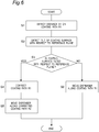
Fig. 6 is a flowchart for explaining coating processing of the coating apparatus ofFig. 1 . -
Fig. 7 is a plan view of another object to be coated. -
Fig. 8 is a side view for explaining a variation of the coating apparatus ofFig. 1 . - Hereinafter, an example of the present disclosure will be described with reference to the accompanying drawings. Note that, in the description below, terms indicating a specific direction or position (for example, terms including "top", "bottom", "right", and "left") are used as necessary. However, the use of those terms is for facilitating the understanding of the present disclosure with reference to the drawings, and the meaning of those terms does not limit the technical scope of the present disclosure. Further, the description below is merely exemplary in nature and is not intended to limit the present disclosure, its application, or its use. Furthermore, the drawings are schematic, and ratios and the like of dimensions do not necessarily agree with actual ones.
- As shown in
Fig. 1 , acoating apparatus 1 according to an embodiment of the present disclosure includes adispenser 10, adrive device 20 capable of driving thedispenser 10, and acontrol device 30 that controls thedispenser 10 and thedrive device 20. - As shown in
Fig. 1 , thedispenser 10 includes anozzle 11 and adisplacement sensor 12. As shown inFigs. 2 and 3 , thenozzle 11 include adischarge port 111 capable of discharging liquid from the vertical direction Z to acoating region 102 provided on an outer peripheral edge of acoating surface 101 of anobject 100 to be coated. As shown inFig. 3 , thedisplacement sensor 12 detects a distance D in the vertical direction Z between thedischarge port 111 and thecoating region 102 of thecoating surface 101.Figs. 2 and 3 illustrate a plate-shaped object 100 to be coated on which the substantiallyrectangular coating surface 101 is arranged along the horizontal plane XY. - The
dispenser 10 is, for example, an air pulse type dispenser that can use a liquid material having any desired viscosity (Pa·s) (for example, alcohol having a viscosity less than 0.001 or cream solder having a viscosity exceeding 100) as the liquid discharged from thedischarge port 111. In thedispenser 10, when thenozzle 11 is tilted with respect to the vertical direction, a discharge amount of liquid discharged from thedischarge port 111 is more likely to vary. This variation becomes more conspicuous as the viscosity of the liquid decreases. For this reason, thenozzle 11 is arranged along the vertical direction Z, and thedischarge port 111 is arranged so that the liquid can be discharged from the vertical direction Z to thecoating region 102. - The
drive device 20 is, for example, a robot, and configured to be movable in the horizontal directions X and Y (seeFig. 2 ) and the vertical direction Z (seeFig. 3 ) by holding thedispenser 10 in a state where liquid can be discharged in the vertical direction Z from thedischarge port 111. - The
control device 30 includes a CPU that performs calculation and the like, a storage medium such as a ROM, RAM, and the like for storing a program or data necessary for controlling thedispenser 10 and thedrive device 20, and an interface unit that performs input and output of a signal to and from an external unit (not shown). As shown inFig. 1 , thecontrol device 30 includes a dispensermovement control unit 31, atilt detection unit 32, and a coating path correction unit 33. The dispensermovement control unit 31, thetilt detection unit 32, and the coating path correction unit 33 are functions realized by the CPU of thecontrol device 30 executing a predetermined program. - The dispenser
movement control unit 31 moves thedispenser 10 along a predetermined coating path R1 for each of theobject 100 to be coated. Further, when the coating path R1 is corrected by the coating path correction unit 33 as described later, the dispensermovement control unit 31 moves thedispenser 10 along a corrected coating path R2 (seeFig. 4 ). - The
tilt detection unit 32 detects a tilt θ of thecoating surface 101 with respect to a reference plane P (a horizontal plane in the present embodiment) extending in a direction intersecting the vertical direction Z (seeFig. 5 ) based on the distance D detected by thedisplacement sensor 12. Specifically, thetilt detection unit 32 detects the tilt θ around arotation axis 110 extending in the X direction on thecoating surface 101 based on a reference distance D1 and a distance D2. The reference distance D1 is detected in advance in at least three preset locations (for example, points A, B, and C shown inFig. 2 ) that are at the outer peripheral edge of thecoating surface 101 of thereference object 100 to be coated and are on the coating path R1. The distance D2 is detected in at least three preset locations (that is, points A, B, and C shown inFig. 4 ) that are at the outer peripheral edge of thecoating surface 101 of theobject 100 to be coated and are on the coating path R1. In the present embodiment, theobject 100 to be coated shown inFigs. 2 and 3 (that is, theobject 100 to be coated in which thecoating surface 101 is horizontally arranged) is used as thereference object 100 to be coated. The reference distance D1 and the distance D2 are the distance D detected in a state where thedischarge port 111 is at the same position with respect to the reference plane P in the vertical direction Z. The reference plane P is not limited to the horizontal plane, and is set according to the position and attitude of thereference object 100 to be coated. - The coating path correction unit 33 corrects the coating path R1 based on the tilt θ of the
coating surface 101 detected by thetilt detection unit 32. For example, when thecoating surface 101 is tilted by an angle θ around therotation axis 110, thecoating surface 101 viewed from the vertical direction Z, which is the liquid discharge direction, becomes smaller by ΔL × 2 in the Y direction, as shown inFigs. 4 and 5 . Thus, the coating path correction unit 33 corrects a length of the coating path R1 in the Y direction according to the tilt θ of thecoating surface 101 detected by thetilt detection unit 32 to create the coating path R2. - The
coating apparatus 1 includes animage sensor 40 that detects a position and attitude of theobject 100 to be coated. Thecontrol device 30 sets the coating path R1 based on the position and attitude of thereference object 100 to be coated detected by theimage sensor 40. - Next, the coating processing using the
coating apparatus 1 will be described with reference toFig. 6 . Note that the processing described below is performed by thecontrol device 30 executing a predetermined program. - As shown in
Fig. 6 , first, the dispensermovement control unit 31 moves thedispenser 10 along the coating path R1 preset based on the position and attitude of thereference object 100 to be coated detected by theimage sensor 40. Then, thedisplacement sensor 12 detects the distance D2 in the vertical direction Z between thedischarge port 111 and thecoating surface 101 in at least three preset locations that are at the outer peripheral edge of thecoating surface 101 and are on the coating path R1 (Step S1). - When the distance D2 is detected, the
tilt detection unit 32 detects the tilt θ of thecoating surface 101 with respect to the reference plane P based on the detected distance D2 and the preset reference distance D1 (Step S2). Then, thecontrol device 30 determines whether thecoating surface 101 is tilted with respect to the reference plane P based on whether thetilt detection unit 32 detects the tilt θ of thecoating surface 101 with respect to the reference plane P (Step S3). - When it is determined that the
coating surface 101 is tilted with respect to the reference plane P, the coating path correction unit 33 corrects the coating path R1 based on the detected tilt θ of thecoating surface 101 with respect to the reference plane P (Step S4). Then, the dispensermovement control unit 31 moves thedispenser 10 along the corrected coating path R2 (Step S5). When it is determined that thecoating surface 101 is not tilted with respect to the reference plane P, the dispensermovement control unit 31 moves thedispenser 10 along the coating path R1 (Step S6). - In Steps S6 and S7, when the
dispenser 10 is moving on the coating path R1 and R2, thecontrol device 30 controls thedispenser 10 to discharge liquid from thedischarge port 111 of thenozzle 11 toward thecoating region 102. Then, when the application of the liquid to thecoating region 102 is completed, the coating processing is completed. - According to the
coating apparatus 1, the tilt θ of thecoating surface 101 with respect to the reference plane P extending in the direction intersecting the vertical direction Z is detected based on the distance D detected by thedisplacement sensor 12, and the coating path R1 is corrected based on the tilt θ of the detectedcoating surface 101. Such a configuration makes it possible to realize thecoating apparatus 1 capable of accurately applying liquid to a predetermined position (that is, the coating region 102) of thecoating surface 101 even if, for example, theobject 100 to be coated is not held and thecoating surface 101 is tilted with respect to the reference plane. - The
tilt detection unit 32 detects the tilt of thecoating surface 101 based on the distance D1 and D2 detected in at least three locations that are at the outer peripheral edge of thecoating surface 101 and are on the coating path R1 and R2. With such a configuration, the tilt θ of thecoating surface 101 with respect to the reference plane P can be detected more accurately. - The
tilt detection unit 32 may detect the tilt of thecoating surface 101 based on the distance D1 and D2 detected in two locations on the coating path R1 and R2. The locations on the coating path R1 and R2 in which the distance D1 and D2 is detected by thetilt detection unit 32 may not be at the outer peripheral edge of thecoating surface 101. - As shown in
Fig. 7 , thecoating surface 101 is not limited to a substantially rectangular shape, and may have any desired shape. Thecoating region 102 is not limited to the outer peripheral edge of thecoating surface 101, and may be set to any other area. - The dispenser
movement control unit 31 may be configured to move thedispenser 10, when thecoating surface 101 is tilted with respect to the reference plane P, at a speed different from that when thecoating surface 101 is not tilted with respect to the reference plane P. For example, when the discharge amount of liquid discharged from thenozzle 11 is constant, the reference plane P is the horizontal plane, and thecoating surface 101 is tilted with respect to the horizontal plane, thedispenser 10 is moved at a speed lower that when thecoating surface 101 is horizontal. Specifically, assuming that the moving speed of thedispenser 10 when thecoating surface 101 is horizontal is V and thecoating surface 101 is tilted by the angle θ with respect to the horizontal plane, the dispensermovement control unit 31 moves thedispenser 10 at the speed of VCosθ. In this manner, a line having substantially the same width as a reference line formed by liquid discharged along the coating path R1 of thereference object 100 to be coated can be formed on the corrected coating path R2 of theobject 100 to be coated. - The dispenser
movement control unit 31 may be configured to move thedispenser 10, when the tilt of thecoating surface 101 with respect to the reference plane P detected by thetilt detection unit 32 is equal to or more than a threshold value, at a speed different from that when thecoating surface 101 is not tilted with respect to the reference plane P. In this manner, the coating processing can be simplified and the load applied on thecontrol device 30 when performing the coating processing can be reduced. The threshold value is decided from the viewpoint of, for example, whether it is possible, even if thecoating surface 101 is tilted with respect to the reference plane P, to draw the substantially same coating track as that when thecoating surface 101 is not tilted with respect to the reference plane P. - Assuming that the
coating surface 101 is tilted by the angle θ with respect to the horizontal plane, the dispensermovement control unit 31 may be configured to move thedispenser 10 along the corrected coating path R2 so that thedischarge port 111 is located at a position separated from thecoating surface 101 by a distance D1/Cosθ in the vertical direction Z. In this manner, a line having substantially the same width as a reference line formed by liquid discharged on the coating path R1 of thereference object 100 to be coated can be formed on the coating path R2 of theobject 100 to be coated. - The
coating apparatus 1 may be configured to be able to correct not only the deviation of thecoating surface 101 with respect to the tilt θ with respect to the reference plane P, but also a rotational deviation on the horizontal plane and a deviation in the vertical direction. For example, the position and attitude of thereference object 100 to be coated detected by theimage sensor 40 can be set as a reference position and a reference attitude. The rotational deviation on the horizontal plane and the deviation in the vertical direction can be detected based on the reference position and the reference attitude as well as on the position and the attitude of theobject 100 to be coated detected by theimage sensor 40. - The various embodiments of the present disclosure have been described in detail with reference to the drawings and, finally, various aspects of the present disclosure will be described. Note that, reference numerals are added in the description below as an example.
- A
coating apparatus 1 of a first aspect of the present disclosure includes: - a
dispenser 10 that includes adischarge port 111 and adisplacement sensor 12, thedischarge port 111 being configured to be capable of discharging liquid from a vertical direction Z to acoating region 102 provided on acoating surface 101 of anobject 100 to be coated, and thedisplacement sensor 12 being configured to detect a distance D1 and D2 in the vertical direction Z between thedischarge port 111 and thecoating region 102; - a
drive device 20 that drives thedispenser 10; - a dispenser
movement control unit 31 that controls thedrive device 20 to move thedispenser 10 along a predetermined coating path R1; - a
tilt detection unit 32 that detects a tilt of thecoating surface 101 with respect to a reference plane P extending in a direction intersecting the vertical direction Z, based on the distance D1 and D2 detected by thedisplacement sensor 12; and - a coating path correction unit 33 that corrects the coating path R1 based on the tilt of the
coating surface 101 detected by thetilt detection unit 32, wherein - when the coating path correction unit 33 corrects the coating path R1, the dispenser
movement control unit 31 moves thedispenser 10 along the corrected coating path R2. - According to the
coating apparatus 1 of the first aspect, the tilt θ of thecoating surface 101 with respect to the reference plane P extending in the direction intersecting the vertical direction Z is detected based on the distance D detected by thedisplacement sensor 12, and the coating path R1 is corrected based on the tilt θ of the detectedcoating surface 101. Such a configuration makes it possible to realize thecoating apparatus 1 capable of accurately applying liquid to a predetermined position (that is, the coating region 102) of thecoating surface 101 even if, for example, theobject 100 to be coated is not held and thecoating surface 101 is tilted with respect to the reference plane. - In the
coating apparatus 1 of a second aspect of the present disclosure,
thetilt detection unit 32 detects the tilt of thecoating surface 101 based on the distance D1 and D2 detected in at least three locations that are at an outer peripheral edge of thecoating surface 101 and are on the coating path R1 and R2. - According to the
coating apparatus 1 of the second aspect, the tilt θ of thecoating surface 101 with respect to the reference plane P can be detected more accurately. - In the
coating apparatus 1 of a third aspect of the present disclosure,
when thecoating surface 101 is tilted with respect to the reference plane P, the dispensermovement control unit 31 moves thedispenser 10 at a speed different from that when thecoating surface 101 is not tilted with respect to the reference plane P. - According to the
coating apparatus 1 of the third aspect, a line having substantially the same width as a reference line formed by liquid discharged along the coating path R1 of thereference object 100 to be coated can be formed on the corrected coating path. R2 of theobject 100 to be coated. - In the
coating apparatus 1 of a fourth aspect of the present disclosure,
when the tilt of thecoating surface 101 with respect to the reference plane P detected by thetilt detection unit 32 is equal to or more than a threshold value, the dispenser movement control unit moves the dispenser at a speed different from that when thecoating surface 101 is not tilted with respect to the reference plane P. - According to the
coating apparatus 1 of the fourth aspect, the coating processing can be simplified and the load applied on thecontrol device 30 when performing the coating processing can be reduced. - In the
coating apparatus 1 of a fifth aspect of the present disclosure,
when the reference plane P is a horizontal plane and thecoating surface 101 is tilted with respect to the horizontal plane, the dispensermovement control unit 31 moves thedispenser 10 at a speed lower than that when thecoating surface 101 is horizontal. - According to the
coating apparatus 1 of the fifth aspect, a line having substantially the same width as that of a reference line formed by liquid discharged along the coating path R1 of thereference object 100 to be coated can be formed on the corrected coating path R2 of theobject 100 to be coated. - Note that, by appropriately combining any embodiment or variation of the various embodiments or variations, the effect of each of them can be achieved. Further, a combination of embodiments, a combination of examples, or a combination of an embodiment and an example is possible, and a combination of features in different embodiments or examples is also possible.
- Although the present disclosure is sufficiently described in connection with preferred embodiments with reference to the accompanying drawings, various variations and modifications are obvious to those skilled in the art. It should be understood that such variations and modifications are included within the scope of the present disclosure in the appended claims as long as they do not deviate from the scope.
- The coating apparatus of the present disclosure can be used, for example, for coating a windshield with a sealer.
-
- 1. coating apparatus
- 10. dispenser
- 11. nozzle
- 111. discharge port
- 12. displacement sensor
- 20. drive device
- 30. control device
- 31. dispenser movement control unit
- 32. tilt detection unit
- 33. coating path correction unit
- 40. image sensor
- 100. object to be coated
- 101. coating surface
- 102. coating region
- 110. rotation axis
- R1, R2. coating path
- P. reference plane
Claims (5)
- A coating apparatus comprising:a dispenser that includes a discharge port and a displacement sensor, the discharge port being configured to be capable of discharging liquid from a vertical direction to a coating region provided on a coating surface of an object to be coated, and the displacement sensor being configured to detect a distance in the vertical direction between the discharge port and the coating region;a drive device that drives the dispenser;a dispenser movement control unit that controls the drive device to move the dispenser along a predetermined coating path;a tilt detection unit that detects a tilt of the coating surface with respect to a reference plane extending in a direction intersecting the vertical direction, based on the distance detected by the displacement sensor; anda coating path correction unit that corrects the coating path based on the tilt of the coating surface detected by the tilt detection unit, whereinwhen the coating path correction unit corrects the coating path, the dispenser movement control unit moves the dispenser along the corrected coating path.
- The coating apparatus according to claim 1, wherein
the tilt detection unit detects the tilt of the coating surface based on the distance detected in at least three locations that are at an outer peripheral edge of the coating surface and are on the coating path. - The coating apparatus according to claim 1 or 2, wherein
when the coating surface is tilted with respect to the reference plane, the dispenser movement control unit moves the dispenser at a speed different from that when the coating surface is not tilted with respect to the reference plane. - The coating apparatus according to claim 3, wherein
when the tilt of the coating surface with respect to the reference plane detected by the tilt detection unit is equal to or more than a threshold value, the dispenser movement control unit moves the dispenser at a speed different from that when the coating surface is not tilted with respect to the reference plane. - The coating apparatus according to claim 3 or 4, wherein
when the reference plane is a horizontal plane and the coating surface is tilted with respect to the horizontal plane, the dispenser movement control unit moves the dispenser at a speed lower than that when the coating surface is horizontal.
Applications Claiming Priority (2)
| Application Number | Priority Date | Filing Date | Title |
|---|---|---|---|
| JP2018209956A JP6988767B2 (en) | 2018-11-07 | 2018-11-07 | Coating device |
| PCT/JP2019/041082 WO2020095653A1 (en) | 2018-11-07 | 2019-10-18 | Coating apparatus |
Publications (2)
| Publication Number | Publication Date |
|---|---|
| EP3858493A1 true EP3858493A1 (en) | 2021-08-04 |
| EP3858493A4 EP3858493A4 (en) | 2022-08-03 |
Family
ID=70611011
Family Applications (1)
| Application Number | Title | Priority Date | Filing Date |
|---|---|---|---|
| EP19883256.0A Withdrawn EP3858493A4 (en) | 2018-11-07 | 2019-10-18 | COATING DEVICE |
Country Status (6)
| Country | Link |
|---|---|
| US (1) | US11596971B2 (en) |
| EP (1) | EP3858493A4 (en) |
| JP (1) | JP6988767B2 (en) |
| KR (1) | KR102467828B1 (en) |
| CN (1) | CN112912182B (en) |
| WO (1) | WO2020095653A1 (en) |
Families Citing this family (1)
| Publication number | Priority date | Publication date | Assignee | Title |
|---|---|---|---|---|
| CN115722420B (en) * | 2022-12-19 | 2023-07-14 | 宁波博信电器有限公司 | Method and system for processing instrument panel sizing, storage medium and intelligent terminal |
Family Cites Families (20)
| Publication number | Priority date | Publication date | Assignee | Title |
|---|---|---|---|---|
| DE1611724B1 (en) * | 1967-08-16 | 1971-03-18 | Henkel & Cie Gmbh | Control device for the closing element of an adhesive applicator |
| NL6909118A (en) * | 1969-06-13 | 1970-12-15 | ||
| JPH05108131A (en) * | 1991-10-16 | 1993-04-30 | Toshiba Corp | Teaching device of robot |
| US5984470A (en) * | 1995-04-20 | 1999-11-16 | Canon Kabushiki Kaisha | Apparatus for producing color filter with alignment error detection |
| JP3831462B2 (en) * | 1997-01-28 | 2006-10-11 | 本田技研工業株式会社 | Sealer coating device for wind glass |
| US6866881B2 (en) * | 1999-02-19 | 2005-03-15 | Speedline Technologies, Inc. | Dispensing system and method |
| JP2000244107A (en) * | 1999-02-24 | 2000-09-08 | Nec Corp | Dispenser with discharge amount control function and cream solder application method |
| JP2001000905A (en) * | 1999-06-22 | 2001-01-09 | Honda Motor Co Ltd | Sealer application method and sealer application apparatus |
| JP4251793B2 (en) * | 2001-07-27 | 2009-04-08 | 株式会社日立プラントテクノロジー | Paste applicator |
| JP2004243215A (en) | 2003-02-13 | 2004-09-02 | Suzuki Motor Corp | Robot teaching method of sealer coating device and sealer coating device |
| KR100794714B1 (en) * | 2004-08-03 | 2008-01-15 | 현대중공업 주식회사 | Continuous welding line following control system of robot and its control method |
| JP4940806B2 (en) * | 2006-07-24 | 2012-05-30 | 株式会社日立プラントテクノロジー | Paste application machine and paste application method |
| CA2705764C (en) | 2007-11-14 | 2016-08-02 | Biosensors International Group, Ltd. | Automated stent coating apparatus and method |
| JP2010110700A (en) * | 2008-11-06 | 2010-05-20 | Ulvac Japan Ltd | Inkjet coater, and parallel degree adjustment apparatus |
| JP5705661B2 (en) * | 2011-06-13 | 2015-04-22 | 株式会社オーテックエレクトロニクス | Liquid dispensing apparatus and liquid dispensing apparatus |
| JP5475059B2 (en) * | 2012-06-13 | 2014-04-16 | キヤノンマシナリー株式会社 | Coating device |
| JP3177944U (en) * | 2012-06-13 | 2012-08-23 | 大東工業株式会社 | Protective glass plate coating device for solar panels |
| US9707584B2 (en) | 2014-07-09 | 2017-07-18 | Nordson Corporation | Dual applicator fluid dispensing methods and systems |
| DE102014116830A1 (en) | 2014-11-18 | 2016-05-19 | Intec Bielenberg Gmbh & Co Kg | Device for insulating mat application |
| JP6590667B2 (en) | 2015-11-30 | 2019-10-16 | キヤノン株式会社 | Imprint apparatus, imprint method, and article manufacturing method |
-
2018
- 2018-11-07 JP JP2018209956A patent/JP6988767B2/en active Active
-
2019
- 2019-10-18 WO PCT/JP2019/041082 patent/WO2020095653A1/en not_active Ceased
- 2019-10-18 KR KR1020217011636A patent/KR102467828B1/en active Active
- 2019-10-18 CN CN201980070738.6A patent/CN112912182B/en active Active
- 2019-10-18 US US17/291,683 patent/US11596971B2/en active Active
- 2019-10-18 EP EP19883256.0A patent/EP3858493A4/en not_active Withdrawn
Also Published As
| Publication number | Publication date |
|---|---|
| KR102467828B1 (en) | 2022-11-18 |
| WO2020095653A1 (en) | 2020-05-14 |
| US20220001416A1 (en) | 2022-01-06 |
| US11596971B2 (en) | 2023-03-07 |
| CN112912182B (en) | 2023-05-02 |
| CN112912182A (en) | 2021-06-04 |
| JP6988767B2 (en) | 2022-01-05 |
| JP2020075213A (en) | 2020-05-21 |
| EP3858493A4 (en) | 2022-08-03 |
| KR20210063372A (en) | 2021-06-01 |
Similar Documents
| Publication | Publication Date | Title |
|---|---|---|
| JP6884109B2 (en) | Board transfer robot and its operation method | |
| EP2894012B1 (en) | Work device | |
| KR101581095B1 (en) | Control device, control method and computer-readable recording medium stroring control program for articulated robot | |
| CN104972240B (en) | Welding inspection robot system | |
| EP3508314A1 (en) | Transport device, transport method, and transport program | |
| US11472476B2 (en) | Steering control device, steering control method, and recording medium | |
| CN104602873A (en) | Method for adjusting robot control parameters, robot system, and robot control device | |
| CN103372519B (en) | Paste coater and slurry coating process and chip adhesive device | |
| US11596971B2 (en) | Coating apparatus | |
| EP2653331A1 (en) | Resin vehicle door structure | |
| JP2022025272A (en) | Three-dimensional object printing device and three-dimensional object printing method | |
| JP6859992B2 (en) | Control methods, robots and robot systems | |
| JP2002205292A (en) | Transfer robot and its control method | |
| CN105329642B (en) | Substrate position offset detection and bearing calibration and the control method of substrate conveying system | |
| EP3539673B1 (en) | Robot system and control method of robot | |
| EP3539674B1 (en) | Robot system and control method of robot | |
| JP2001300875A (en) | Robot system | |
| JP7126204B2 (en) | Conveyor | |
| JP7559606B2 (en) | Display control device, display device, and image display control method | |
| US12434391B2 (en) | Production system | |
| CN101380852A (en) | Nozzle height correction method | |
| KR20240110643A (en) | Control device for substrate transport robot and control method for joint motor | |
| JP7746752B2 (en) | Coating device and coating device control method | |
| JP2005162422A (en) | Positioning method of conveyed product on conveyor | |
| US10538352B2 (en) | Method and system for packaging a container |
Legal Events
| Date | Code | Title | Description |
|---|---|---|---|
| STAA | Information on the status of an ep patent application or granted ep patent |
Free format text: STATUS: THE INTERNATIONAL PUBLICATION HAS BEEN MADE |
|
| PUAI | Public reference made under article 153(3) epc to a published international application that has entered the european phase |
Free format text: ORIGINAL CODE: 0009012 |
|
| STAA | Information on the status of an ep patent application or granted ep patent |
Free format text: STATUS: REQUEST FOR EXAMINATION WAS MADE |
|
| 17P | Request for examination filed |
Effective date: 20210428 |
|
| AK | Designated contracting states |
Kind code of ref document: A1 Designated state(s): AL AT BE BG CH CY CZ DE DK EE ES FI FR GB GR HR HU IE IS IT LI LT LU LV MC MK MT NL NO PL PT RO RS SE SI SK SM TR |
|
| DAV | Request for validation of the european patent (deleted) | ||
| DAX | Request for extension of the european patent (deleted) | ||
| A4 | Supplementary search report drawn up and despatched |
Effective date: 20220704 |
|
| RIC1 | Information provided on ipc code assigned before grant |
Ipc: B05C 11/10 20060101ALI20220628BHEP Ipc: B05C 5/00 20060101AFI20220628BHEP |
|
| STAA | Information on the status of an ep patent application or granted ep patent |
Free format text: STATUS: EXAMINATION IS IN PROGRESS |
|
| 17Q | First examination report despatched |
Effective date: 20240405 |
|
| STAA | Information on the status of an ep patent application or granted ep patent |
Free format text: STATUS: THE APPLICATION IS DEEMED TO BE WITHDRAWN |
|
| 18D | Application deemed to be withdrawn |
Effective date: 20241008 |