EP3858209A1 - Movable electric device - Google Patents
Movable electric device Download PDFInfo
- Publication number
- EP3858209A1 EP3858209A1 EP18939194.9A EP18939194A EP3858209A1 EP 3858209 A1 EP3858209 A1 EP 3858209A1 EP 18939194 A EP18939194 A EP 18939194A EP 3858209 A1 EP3858209 A1 EP 3858209A1
- Authority
- EP
- European Patent Office
- Prior art keywords
- electrode
- positive electrode
- negative electrode
- contact detection
- electric device
- Prior art date
- Legal status (The legal status is an assumption and is not a legal conclusion. Google has not performed a legal analysis and makes no representation as to the accuracy of the status listed.)
- Granted
Links
Images





Classifications
-
- B—PERFORMING OPERATIONS; TRANSPORTING
- B25—HAND TOOLS; PORTABLE POWER-DRIVEN TOOLS; MANIPULATORS
- B25J—MANIPULATORS; CHAMBERS PROVIDED WITH MANIPULATION DEVICES
- B25J19/00—Accessories fitted to manipulators, e.g. for monitoring, for viewing; Safety devices combined with or specially adapted for use in connection with manipulators
- B25J19/02—Sensing devices
-
- A—HUMAN NECESSITIES
- A47—FURNITURE; DOMESTIC ARTICLES OR APPLIANCES; COFFEE MILLS; SPICE MILLS; SUCTION CLEANERS IN GENERAL
- A47L—DOMESTIC WASHING OR CLEANING; SUCTION CLEANERS IN GENERAL
- A47L9/00—Details or accessories of suction cleaners, e.g. mechanical means for controlling the suction or for effecting pulsating action; Storing devices specially adapted to suction cleaners or parts thereof; Carrying-vehicles specially adapted for suction cleaners
- A47L9/28—Installation of the electric equipment, e.g. adaptation or attachment to the suction cleaner; Controlling suction cleaners by electric means
- A47L9/2805—Parameters or conditions being sensed
- A47L9/281—Parameters or conditions being sensed the amount or condition of incoming dirt or dust
-
- A—HUMAN NECESSITIES
- A47—FURNITURE; DOMESTIC ARTICLES OR APPLIANCES; COFFEE MILLS; SPICE MILLS; SUCTION CLEANERS IN GENERAL
- A47L—DOMESTIC WASHING OR CLEANING; SUCTION CLEANERS IN GENERAL
- A47L11/00—Machines for cleaning floors, carpets, furniture, walls, or wall coverings
- A47L11/40—Parts or details of machines not provided for in groups A47L11/02 - A47L11/38, or not restricted to one of these groups, e.g. handles, arrangements of switches, skirts, buffers, levers
- A47L11/4011—Regulation of the cleaning machine by electric means; Control systems and remote control systems therefor
-
- A—HUMAN NECESSITIES
- A47—FURNITURE; DOMESTIC ARTICLES OR APPLIANCES; COFFEE MILLS; SPICE MILLS; SUCTION CLEANERS IN GENERAL
- A47L—DOMESTIC WASHING OR CLEANING; SUCTION CLEANERS IN GENERAL
- A47L11/00—Machines for cleaning floors, carpets, furniture, walls, or wall coverings
- A47L11/24—Floor-sweeping machines, motor-driven
-
- A—HUMAN NECESSITIES
- A47—FURNITURE; DOMESTIC ARTICLES OR APPLIANCES; COFFEE MILLS; SPICE MILLS; SUCTION CLEANERS IN GENERAL
- A47L—DOMESTIC WASHING OR CLEANING; SUCTION CLEANERS IN GENERAL
- A47L11/00—Machines for cleaning floors, carpets, furniture, walls, or wall coverings
- A47L11/40—Parts or details of machines not provided for in groups A47L11/02 - A47L11/38, or not restricted to one of these groups, e.g. handles, arrangements of switches, skirts, buffers, levers
- A47L11/4002—Installations of electric equipment
-
- A—HUMAN NECESSITIES
- A47—FURNITURE; DOMESTIC ARTICLES OR APPLIANCES; COFFEE MILLS; SPICE MILLS; SUCTION CLEANERS IN GENERAL
- A47L—DOMESTIC WASHING OR CLEANING; SUCTION CLEANERS IN GENERAL
- A47L11/00—Machines for cleaning floors, carpets, furniture, walls, or wall coverings
- A47L11/40—Parts or details of machines not provided for in groups A47L11/02 - A47L11/38, or not restricted to one of these groups, e.g. handles, arrangements of switches, skirts, buffers, levers
- A47L11/4036—Parts or details of the surface treating tools
- A47L11/4038—Disk shaped surface treating tools
-
- A—HUMAN NECESSITIES
- A47—FURNITURE; DOMESTIC ARTICLES OR APPLIANCES; COFFEE MILLS; SPICE MILLS; SUCTION CLEANERS IN GENERAL
- A47L—DOMESTIC WASHING OR CLEANING; SUCTION CLEANERS IN GENERAL
- A47L11/00—Machines for cleaning floors, carpets, furniture, walls, or wall coverings
- A47L11/40—Parts or details of machines not provided for in groups A47L11/02 - A47L11/38, or not restricted to one of these groups, e.g. handles, arrangements of switches, skirts, buffers, levers
- A47L11/4036—Parts or details of the surface treating tools
- A47L11/4041—Roll shaped surface treating tools
-
- A—HUMAN NECESSITIES
- A47—FURNITURE; DOMESTIC ARTICLES OR APPLIANCES; COFFEE MILLS; SPICE MILLS; SUCTION CLEANERS IN GENERAL
- A47L—DOMESTIC WASHING OR CLEANING; SUCTION CLEANERS IN GENERAL
- A47L11/00—Machines for cleaning floors, carpets, furniture, walls, or wall coverings
- A47L11/40—Parts or details of machines not provided for in groups A47L11/02 - A47L11/38, or not restricted to one of these groups, e.g. handles, arrangements of switches, skirts, buffers, levers
- A47L11/4063—Driving means; Transmission means therefor
- A47L11/4066—Propulsion of the whole machine
-
- A—HUMAN NECESSITIES
- A47—FURNITURE; DOMESTIC ARTICLES OR APPLIANCES; COFFEE MILLS; SPICE MILLS; SUCTION CLEANERS IN GENERAL
- A47L—DOMESTIC WASHING OR CLEANING; SUCTION CLEANERS IN GENERAL
- A47L11/00—Machines for cleaning floors, carpets, furniture, walls, or wall coverings
- A47L11/40—Parts or details of machines not provided for in groups A47L11/02 - A47L11/38, or not restricted to one of these groups, e.g. handles, arrangements of switches, skirts, buffers, levers
- A47L11/4072—Arrangement of castors or wheels
-
- B—PERFORMING OPERATIONS; TRANSPORTING
- B25—HAND TOOLS; PORTABLE POWER-DRIVEN TOOLS; MANIPULATORS
- B25J—MANIPULATORS; CHAMBERS PROVIDED WITH MANIPULATION DEVICES
- B25J11/00—Manipulators not otherwise provided for
- B25J11/008—Manipulators for service tasks
- B25J11/0085—Cleaning
-
- B—PERFORMING OPERATIONS; TRANSPORTING
- B25—HAND TOOLS; PORTABLE POWER-DRIVEN TOOLS; MANIPULATORS
- B25J—MANIPULATORS; CHAMBERS PROVIDED WITH MANIPULATION DEVICES
- B25J9/00—Program-controlled manipulators
- B25J9/16—Program controls
- B25J9/1679—Program controls characterised by the tasks executed
- B25J9/1684—Tracking a line or surface by means of sensors
-
- G—PHYSICS
- G01—MEASURING; TESTING
- G01N—INVESTIGATING OR ANALYSING MATERIALS BY DETERMINING THEIR CHEMICAL OR PHYSICAL PROPERTIES
- G01N27/00—Investigating or analysing materials by the use of electric, electrochemical, or magnetic means
- G01N27/02—Investigating or analysing materials by the use of electric, electrochemical, or magnetic means by investigating impedance
-
- G—PHYSICS
- G01—MEASURING; TESTING
- G01N—INVESTIGATING OR ANALYSING MATERIALS BY DETERMINING THEIR CHEMICAL OR PHYSICAL PROPERTIES
- G01N27/00—Investigating or analysing materials by the use of electric, electrochemical, or magnetic means
- G01N27/02—Investigating or analysing materials by the use of electric, electrochemical, or magnetic means by investigating impedance
- G01N27/04—Investigating or analysing materials by the use of electric, electrochemical, or magnetic means by investigating impedance by investigating resistance
-
- G—PHYSICS
- G01—MEASURING; TESTING
- G01N—INVESTIGATING OR ANALYSING MATERIALS BY DETERMINING THEIR CHEMICAL OR PHYSICAL PROPERTIES
- G01N27/00—Investigating or analysing materials by the use of electric, electrochemical, or magnetic means
- G01N27/02—Investigating or analysing materials by the use of electric, electrochemical, or magnetic means by investigating impedance
- G01N27/22—Investigating or analysing materials by the use of electric, electrochemical, or magnetic means by investigating impedance by investigating capacitance
- G01N27/226—Construction of measuring vessels; Electrodes therefor
-
- A—HUMAN NECESSITIES
- A47—FURNITURE; DOMESTIC ARTICLES OR APPLIANCES; COFFEE MILLS; SPICE MILLS; SUCTION CLEANERS IN GENERAL
- A47L—DOMESTIC WASHING OR CLEANING; SUCTION CLEANERS IN GENERAL
- A47L2201/00—Robotic cleaning machines, i.e. with automatic control of the travelling movement or the cleaning operation
- A47L2201/04—Automatic control of the travelling movement; Automatic obstacle detection
-
- A—HUMAN NECESSITIES
- A47—FURNITURE; DOMESTIC ARTICLES OR APPLIANCES; COFFEE MILLS; SPICE MILLS; SUCTION CLEANERS IN GENERAL
- A47L—DOMESTIC WASHING OR CLEANING; SUCTION CLEANERS IN GENERAL
- A47L2201/00—Robotic cleaning machines, i.e. with automatic control of the travelling movement or the cleaning operation
- A47L2201/06—Control of the cleaning action for autonomous devices; Automatic detection of the surface condition before, during or after cleaning
Definitions
- the present disclosure relates to the technical field of cleaning, and particularly to a movable electric device.
- sweeping robots When detecting pet excrements, sweeping robots typically use non-contact sensors such as infrared sensors and odor sensors. Since the sensors do not directly contact the excrements, detection of the excrements is rendered inaccurate, which is not conducive for the sweeping machine to make an accurate judgment of the detection results.
- non-contact sensors such as infrared sensors and odor sensors. Since the sensors do not directly contact the excrements, detection of the excrements is rendered inaccurate, which is not conducive for the sweeping machine to make an accurate judgment of the detection results.
- a main object of the present disclosure is to provide a movable electric device, for improving an accuracy with which the movable electric device detects diffusible dirt.
- the movable electric device configured to detect or clean up wastes.
- the movable electric device includes a movable device body and a contact detection electrode.
- the movable device body has an electric drive means.
- the contact detection electrode is mounted on the movable device body. In response to the contact detection electrode contacting diffusible dirt, a resistance, capacitance or impedance of the contact detection electrode varies.
- the contact detection electrode includes a ring-shaped positive electrode and a ring-shaped negative electrode.
- the ring-shaped negative electrode is provided to sleeve an outer side of the ring-shaped positive electrode or provided inside the ring-shaped positive electrode.
- a detection area is formed between the ring-shaped positive electrode and the ring-shaped negative electrode.
- the contact detection electrode includes a comb-teeth positive electrode and a comb-teeth negative electrode.
- the comb-teeth positive electrode includes a positive electrode connecting arm and a plurality of positive electrode teeth arranged along a length direction of the positive electrode connecting arm.
- the comb-teeth negative electrode includes a negative electrode connecting arm and a plurality of negative electrode teeth arranged along a length direction of the negative electrode connecting arm.
- the positive electrode teeth and the negative electrode teeth are arranged in a staggered manner to form a detection area between the positive electrode teeth and the negative electrode teeth.
- the contact detection electrode includes a curvilinear positive electrode and a curvilinear negative electrode.
- the curvilinear positive electrode bends and extends along a direction.
- the curvilinear negative electrode extends along a length direction of the curvilinear positive electrode to form a detection area between the curvilinear positive electrode and the curvilinear negative electrode.
- the curvilinear positive electrode extends in the form of one or more of a sine curve, a cosine curve, a normal distribution curve, a parabola, a wave polyline, and a square wave curve.
- the curvilinear negative electrode extends in the form of one or more of a sine curve, a cosine curve, a normal distribution curve, a parabola, a wave broken line, and a square wave curve.
- the contact detection electrode includes a plurality of positive and negative electrode points arranged in a staggered manner. A detection area is formed between the positive electrode points and the negative electrode points.
- the contact detection electrode includes a plurality of positive electrode plates and a plurality of negative electrodes.
- the plurality of positive electrode plates are arranged radially from the center to the periphery.
- the plurality of negative electrodes are located in gaps between adjacent positive electrode plates.
- a detection area is formed between the positive electrode plates and the negative electrodes.
- the contact detection electrode includes a plurality of negative electrode plates and a plurality of positive electrodes.
- the plurality of negative electrode plates are arranged radially from the center to the periphery.
- the plurality of positive electrodes are located in gaps between adjacent negative electrode plates.
- a detection area is formed between the negative electrode plates and the positive electrodes.
- the negative electrodes are arranged in a circle with a radiation center of the positive electrode plates as a center of the circle.
- the positive electrodes are arranged in a circle with a radiation center of the negative electrode plates as a center of the circle.
- the contact detection electrode includes a central positive electrode and a plurality of negative electrodes arranged circumferentially around the central positive electrode. A detection area is formed between the central positive electrode and the negative electrodes.
- the contact detection electrode includes a central negative electrode and a plurality of positive electrodes arranged circumferentially around the central negative electrode. The detection area is formed between the central negative electrode and the positive electrodes.
- the contact detection electrode includes a positive electrode and a negative electrode.
- a thickness of the positive electrode is greater than a thickness of the negative electrode, or the thickness of the negative electrode is greater than the thickness of the positive electrode.
- the contact detection electrode includes a positive electrode and a negative electrode.
- the positive electrode and/or the negative electrode have pointed teeth.
- the positive electrode and/or the negative electrode have arc-shaped transitions.
- a thickness of at least one group of the contact detection electrodes is greater than a thickness of the other contact detection electrodes.
- the contact detection electrode includes a positive electrode and a negative electrode.
- the positive electrode and the negative electrode have a flexibility and a length of the positive electrode and a length of the negative electrode are smaller than half of a distance between adjacent positive and negative electrodes.
- the movable device body includes a housing and a roller provided at a bottom portion of the housing.
- the contact detection electrode is provided on an outer peripheral surface and/or side portion of the roller.
- the contact detection electrode includes a positive electrode and a negative electrode.
- the positive electrode includes a plurality of positive electrode plates connected by a connector. A positive electrode gap is provided between two adjacent positive electrode plates.
- the negative electrode includes a plurality of negative electrode plates connected by a connector. A negative electrode gap is provided between two adjacent negative electrode plates.
- the positive electrode and the negative electrode are arranged in parallel. Further, the positive electrode plates are configured to correspond to the negative electrode gaps, and the negative electrode plates are configured to correspond to the positive electrode gaps.
- the positive electrode and the negative electrode are arranged in a ring shape, and surround the outer peripheral surface of the roller along a peripheral direction of the roller.
- the movable device body includes a first baffle provided on a axial side of the roller.
- the contact detection electrode is provided on the first baffle.
- the contact detection electrode is mounted at a bottom portion of the first baffle.
- the contact detection electrode includes a positive electrode and a negative electrode.
- the positive electrode and/or the negative electrode are/is mounted on a side of the first baffle facing the roller, and the negative electrode and/or the positive electrode are mounted on a side of the roller facing the first baffle.
- a rotating shaft of the roller is rotatably connected to the first baffle.
- a peripheral side wall of the roller is provided with a mounting cavity.
- the contact detection electrode is mounted in the mounting cavity.
- a top portion of the contact detection electrode is flush with an opening of the mounting cavity or lower than an edge of the opening.
- the movable device body includes a second baffle provided on an upper portion of the roller.
- the contact detection electrode is mounted on the second baffle.
- the contact detection electrode includes a positive electrode and a negative electrode.
- the positive electrode and/or the negative electrode are mounted on the second baffle; and the negative electrode and/or the positive electrode are mounted on the roller.
- Groups of the contact detection electrodes are distributed on multiple positions of the movable device body.
- the movable device body includes a chassis.
- the contact detection electrode is provided on the chassis.
- the contact detection electrode includes an insulating substrate, and a positive electrode and a negative electrode both mounted on the insulating substrate. A detection area is formed between the positive electrode and the negative electrode.
- the contact detection electrode includes a fixing part and a detecting part connected to the fixing part.
- the fixing part is detachably connected to the chassis.
- the detecting part extends in a direction away from the fixing part.
- the contact detection electrode is configured in an elongate-strip shape, and extends along a peripheral direction of the chassis.
- the contact detection electrode is provided in proximity to an edge of a front side of the chassis.
- the movable device body includes a side brush.
- a mounting platform of the side brush protrudes outward.
- the contact detection electrode is provided on the mounting platform.
- the number of side brushes is two.
- the two side brushes are provided on a left side and a right side of a front side of the bottom portion of the housing respectively.
- the contact detection electrode is mounted on a side of the mounting platform facing the middle.
- the contact detection electrodes are mounted on the side brushes.
- the movable device body includes a rolling brush provided in the middle of the housing.
- the contact detection electrode is mounted on the rolling brush.
- the contact detection electrode is a flexible electrode.
- the contact detection electrode is arranged in parallel with bristles of the rolling brush.
- the movable device body includes a housing.
- the contact detection electrode is provided on a peripheral side wall of the housing.
- the contact detection electrode includes a flexible substrate.
- the positive electrode and the negative electrode of the contact detection electrode are mounted on the flexible substrate.
- the flexible substrate is wound and mounted on the peripheral side wall of the housing.
- the positive electrode includes a plurality of positive electrode plates.
- the negative electrode includes a plurality of negative electrode plates. The positive electrode plates and the negative electrode plates are arranged sequentially in a staggered manner on the flexible substrate.
- the positive electrode plates and the negative electrode plates extend along a length direction of the flexible substrate or along a width direction of the flexible substrate.
- the positive electrode plates and/or the negative electrode plates are attached and fixed to a surface of the flexible substrate.
- each of the positive electrode plates and/or the negative electrode plates is connected to the surface of the flexible substrate, and the other end thereof extends in a direction away from the flexible substrate.
- the flexible substrate is mounted on a lower portion of the peripheral side wall of the housing.
- the positive electrode plates and/or the negative electrode plates extend towards the bottom portion of the housing.
- the positive electrode includes positive electrode bumps
- the negative electrode includes negative electrode bumps.
- the positive electrode bumps and the negative electrode bumps are arranged sequentially in a dot matrix.
- the dot matrix is arranged on the surface of the flexible substrate.
- the movable electric device is a movable detection device or a movable cleaning device.
- a capacitance value, resistance value or impedance value of the contact detection electrode varies, so that current in a detection circuit where the contact detection electrode lies varies.
- the variation in the capacitance value, resistance value or impedance value of the contact detection electrode, or the variation in the current in the detection circuit it is judged whether the currently detected object is diffusible dirt. Since the contact detection electrode directly contacts the object for detection, numerous factors that affect the detection accuracy are accordingly avoided.
- the accuracy of the detection results is greatly improved, thereby facilitating improvement of an accuracy with which the movable electric device detects the diffusible dirt and facilitating an accurate judgment and operation of the movable electric device.
- the present disclosure mainly proposes a movable electric device.
- the movable electric device can be a movable cleaning device such as a sweeping robot (with detecting and cleaning functions at the same time), or an electric detection device with only a detecting function.
- the movable electric device has a contact detection electrode.
- the contact detection electrode has a detection area. In response to that the contact detection electrode comes into contact with diffusible dirt, one of a resistance value, capacitance value and impedance value of the contact detection electrode varies, so that current in a detection circuit of the movable electric device varies.
- a control circuit of the movable electric device triggers a prompt apparatus of the movable electric device according to the variation in the resistance value, capacitance value or impedance value of the contact detection electrode, or according to the variation in the current value (or the value of current) in the detection circuit.
- the prompt apparatus may send out an alert to the outside via one or more of light, sound and vibration.
- the prompt apparatus may also send a signal to a designated terminal and send a prompt through this terminal.
- the movable electric device switches the cleaning device to a cleaning tool for diffusible dirt to remove the diffusible dirt.
- the movable electric device stops moving to avoid diffusion of the dirt and contaminating the ground to be cleaned.
- diffusible dirt usually has a certain humidity and viscosity, and is prone to diffuse along with carriers, such as animal excrements, melted candies, liquids (e.g., water), flowable media (e.g., tomato sauce, soup) and the like.
- a movable electric device is configured to detect or clean up wastes.
- the movable electric device has a movable device body 100 including an electric drive means or an electric actuator.
- the electric drive means may be a motor, an electrically driven hydraulic pump or pneumatic pump, electromagnetic-induction drive equipment, or any other devices driven by electricity.
- the movable electric device further includes a contact detection electrode 200 which is mounted on the movable device body 100. In response to the contact detection electrode 200 contacting diffusible dirt, a resistance, capacitance, or impedance of the contact detection electrode 200 varies.
- the movable device body 100 includes a housing 110 and a roller 130 or a wheel 130.
- the roller 130 is disposed at a bottom portion of the housing 110 and is rotatably connected to the housing 110.
- the electric drive means is connected to the roller 130 to drive the roller 130 to roll.
- the electric drive means is connected to the housing 110.
- the housing 110 can have many shapes, such as polygon, ellipse, circle, etc. In the case of a same volume, in order to enable the movable electric device to enter a narrower space, the housing 110 is configured to be circular.
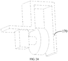
- a first baffle 170 is provided on a side of the roller 130 in an axial direction of the roller 130, and a second baffle 160 is provided on a top portion of the roller 130.
- a bottom portion of the housing 110 is provided with a chassis 120 (the chassis 120 does not belong to the housing 110), or the bottom portion of the housing 110 is the chassis 120, that is, the chassis 120 is a part of the housing 110.
- a rolling brush 150 for cleaning up ground dusts and the like is mounted on the housing 110, and is driven by a motor.
- a side brush 140 is also provided on the chassis 120. The side brush 140 extends from the chassis 120 out of the housing 110 to expand the cleaning range of the movable electric device, thereby improving the cleaning efficiency.
- a capacitance value, resistance value or impedance value of the contact detection electrode 200 varies, so that current in the detection circuit where the contact detection electrode 200 lies varies. According to the variation in the capacitance value, resistant value or impedance value of the contact detection electrode 200 or the variation in the current in the detection circuit, it is judged whether the currently detected object is diffusible dirt.
- the contact detection electrode 200 directly contacts the object for detection, numerous factors that affect the detection accuracy are accordingly avoided, so that the accuracy of the detection results is greatly improved, thereby facilitating the improvement of an accuracy with which the movable electric device detects the diffusible dirt and facilitating an accurate judgment and operation of the movable electric device.
- judging whether the currently detected object is diffusible dirt according to the capacitance value, resistance value, impedance value or current value can be achieved by a comparison circuit.
- a preset capacitance value is configured; and when the detected capacitance value is greater than or equal to the preset capacitance value, the current object is judged to be diffusible dirt, and when the detected capacitance value is smaller than the preset capacitance value, the current object is judged to be non-diffusible dirt.
- Said judging whether the currently detected object is diffusible dirt according to the capacitance value, resistance value, impedance value or current value can also be realized by software.
- the detected capacitance value may be compared with a capacitance value pre-stored in a memory of the movable electric device. Different capacitance values that are stored correspond to different types of objects. One or more of the objects are certainly diffusing dirt.
- the contact detection electrode 200 may be provided in any of such positions as a peripheral side wall of the housing 110, the chassis 120, the roller 130, the first baffle 170, the second baffle 160, the side brush 140, and the rolling brush 150 etc. Some specific forms of the contact detection electrode 200, specific positions where the contact detection electrode 200 is arranged, preferred electrode forms at the specific positions, and the like will be specifically introduced below.
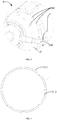
- the contact detection electrode 200 includes a ring-shaped positive electrode 211 and a ring-shaped negative electrode 212.
- the ring-shaped negative electrode 212 is sleeved at an outer side of the ring-shaped positive electrode 211.
- the ring-shaped negative electrode 212 is disposed inside the ring-shaped positive electrode 211.
- a detection area is formed between the ring-shaped positive electrode 211 and the ring-shaped negative electrode 212.
- the ring-shaped positive electrode 211 is configured to be in a ring shape.
- Multiple ring shapes may be adopted.
- the ring-shaped positive electrode 211 is configured in a circle, an ellipse, a triangle, a square, or other polygon.
- the ring shape herein can be a complete closed ring, and can also be a ring with a small-sized opening. That is, the ring shape describes an extending tendency of the electrode.
- the ring-shaped negative electrode 212 is also configured to be in a ring shape; and its shape can be a circle, an ellipse, a triangle, a quadrangle, or the like.
- the shape of the ring-shaped negative electrode 212 can be equivalent to that of the ring-shaped positive electrode 211, or can be completely different therefrom.
- the ring-shaped negative electrode 212 may be configured to be sleeved at the outside of the ring-shaped positive electrode 211, or may be mounted within an area enclosed by the ring-shaped positive electrode 211.
- a separation area is provided between the ring-shaped positive electrode 211 and the ring-shaped negative electrode 212. The separation area functions as a detection area of the contact electrode. When an object enters the detection area, a resistance, capacitance or impedance of the contact detection electrode 200 varies.
- the main control circuit of the movable electric device acquires the parameter variation, and judges whether the object is diffusible dirt according to the variation.
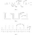
- the contact detection electrode 200 includes a comb-teeth positive electrode 251 and a comb-tooth negative electrode 254.
- the comb-teeth positive electrode 251 includes a positive electrode connecting arm 252 and a plurality of positive electrode teeth 253 arranged along a length direction of the positive electrode connecting arm 252.
- the comb-tooth negative electrode 254 includes a negative electrode connecting arm 256 and a plurality of negative electrode teeth 255 arranged along a length direction of the negative electrode connecting arm 256.
- the positive electrode teeth 253 and the negative electrode teeth 255 are arranged in a staggered manner to form a detection area between the positive electrode teeth 253 and the negative electrode teeth 255.
- the positive electrode teeth 253 of the comb-teeth positive electrode 251 are configured in an elongate-strip shape. One end of the positive electrode teeth 253 is connected to the positive electrode connecting arm 252, and the other end thereof extends in a direction away from the positive electrode connecting arm 252.
- the positive electrode teeth 253 and the connecting arm are configured at an included angle between 30° and 150°.
- the positive electrode teeth 253 and the positive electrode connecting arm 252 being perpendicular to each other is taken as an example.
- the positive electrode teeth 253 can be arranged on a same side of the positive electrode connecting arm 252 or on two opposite sides of the connecting arm 252. Of course, in some embodiments, the positive electrode teeth 253 may also be arranged along a peripheral direction of the connecting arm.
- the positive electrode teeth 253 and the positive electrode connecting arm 252 may be configured integrally or separately.
- the negative electrode teeth 255 of the comb-teeth negative electrode 254 are configured in an elongate-strip shape. One end of the negative electrode teeth 255 is connected to the negative electrode connecting arm 256, and the other end thereof extends in a direction away from the negative electrode connecting arm 252.
- the negative electrode teeth 253 and the connecting arm are configured at an included angle between 30° and 150°.
- the negative electrode teeth 253 and the negative electrode connecting arm 256 being perpendicular to each other is taken as an example.
- the negative electrode teeth 255 can be arranged on a same side of the negative electrode connecting arm 256 or on two opposite sides of the connecting arm. Of course, in some embodiments, the negative electrode teeth 252 may also be arranged along a peripheral direction of the negative electrode connecting arm 256.
- the negative electrode teeth 255 and the negative electrode connecting arm 256 may be configured integrally or separately.
- the positive electrode connecting arm 252 and the negative electrode connecting arm 256 are configured in parallel.
- the positive electrode teeth 253 extend toward the negative electrode connecting arm 256.
- the negative electrode teeth 255 extend toward the positive electrode connecting arm 252.
- the positive electrode teeth 253 and the negative electrode teeth 255 are arranged in a spaced and staggered manner.
- a detection area is formed between the positive electrode teeth 253 and the negative electrode teeth 255.
- a comb-teeth positive electrode 251 mates with a plurality of comb-teeth negative electrodes 254, and a comb-teeth negative electrode 254 mates with a plurality of comb-teeth positive electrodes 251.
- the contact detection electrode 200 includes a curvilinear positive electrode 222 and a curvilinear negative electrode 221.
- the curvilinear positive electrode 222 bends and extends in a direction.
- the curvilinear negative electrode 221 extends along a length direction of the curvilinear positive electrode 222 to form a detection area between the curvilinear positive electrode 222 and the curvilinear negative electrode 221.
- the curvilinear positive electrode 222 is configured in a curved linear shape, and its extending direction can be configured according to actual demand. That is, the extending direction of the curvilinear positive electrode 222 can be in the shape of a preset equation curve, such as a sine curve, a cosine curve, a parabola, a normal distribution curve, or the like.
- the curvilinear positive electrode 222 may also extend in a square wave, and can also be configured in a wave-folded line or a wave polyline.
- the curvilinear negative electrode 221 is configured in a curved linear shape, and its extending direction can be configured according to actual demand.
- the extending direction of curvilinear negative electrode 221 can be in the shape of a preset equation curve, such as a sine curve, a cosine curve, a parabola, a normal distribution curve, or the like.
- the curvilinear negative electrode 221 may also extend in a square wave, and can also be configured in a wave-folded line.
- the curvilinear positive electrode 222 extends in the form of one or more of a sine curve, a cosine curve, and a square wave curve
- the curvilinear negative electrode 221 extends in the form of one or more of a sine curve, a cosine curve, and a square wave curve.
- the curvilinear positive electrode 222 and the curvilinear negative electrode 221 are configured in parallel, and a detection area is enclosed and formed between the curvilinear positive electrode 222 and the curvilinear negative electrode 221.
- the shape of the curvilinear positive electrode 222 and the shape of the curvilinear negative electrode 221 can be identical or different.
- the shapes of the curvilinear positive electrode 222 and the curvilinear negative electrode 221 being identical is taken as an example.
- the contact detection electrode 200 includes a plurality of positive electrode points 231 and negative electrode points 232.
- the positive electrode points 231 and the negative electrode points 232 are arranged in a staggered manner.
- a detection area is formed between the positive electrode points 231 and the negative electrode points 232.
- the positive electrode and the negative electrode of the contact detection electrode 200 are arranged in a dot shape.
- a plurality of positive electrode points 231 and negative electrode points 232 may be arranged in a desired shape, for example, a straight line, a curve, a circle, an ellipse, a polygon (a triangle, a rhombus, etc.), or the like, according to actual operating conditions.
- the positive electrode points 231 and the negative electrode points 232 have such small volumes that a shape in which the positive electrode points 231 and the negative electrode points 232 are arranged may perfectly fit with the actually desired shape.
- the contact detection electrode 200 may not only be arranged at any desired position to improve adaptability of the contact detection electrode 200, but also may detect positions which can hardly be detected by ordinary electrodes, thereby increasing the detection range of the contact detection electrode 200.
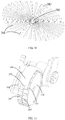
- the contact detection electrode 200 includes a plurality of positive electrode plates 281 and a plurality of negative electrodes 282.
- the plurality of positive electrode plates 281 are arranged radially from the center to the periphery.
- the plurality of negative electrodes 282 are located in gaps between adjacent positive electrode plates 281.
- a detection area is formed between the positive electrode plates 281 and the negative electrodes 282.
- the contact detection electrode 200 includes a plurality of negative electrode 282 plates and a plurality of positive electrodes.
- the plurality of negative electrode 282 plates are arranged radially from the center to the periphery.
- the plurality of positive electrodes are located in gaps between the adjacent negative electrode 282 plates.
- a detection area is formed between the negative electrode 282 plates and the positive electrodes.
- the positive electrode plates 281 are configured in an elongate-strip shape which can be any of an elongate rectangle, trapezoid, triangle, and the like.
- An end of each of the plurality of positive electrode plates 281 extends toward a same convergence point, and the other end thereof extends radially in a direction away from the convergence point. Ends of the positive electrode plates 281 adjacent to the convergence point may be connected or not connected.
- the connection of ends of the positive electrode plates 281 adjacent to the convergence point as an example facilitates power supply to all the positive electrode plates 281 at the same time.
- the gap may be a uniform gap or a gradual gap.
- the negative electrodes 282 can have a variety of forms, such as an elongate-strip shape, a block shape, a dot shape, etc.. When the negative electrodes 282 are in the elongate-strip shape, the negative electrodes 282 extend along a length direction of the gap. When the negative electrodes 282 are in the block shape and the dot shape, the negative electrodes 282 are arranged in the gap. A plurality of negative electrodes 282 may be provided in a same gap. In some embodiments, ends of a plurality of positive electrode plates 281 adjacent to the convergence point enclose a central area in which the negative electrodes 282 are provided.
- the negative electrodes 282 are arranged radially in a star shape, and the positive electrodes are embedded in the gaps between the adjacent negative electrodes 282.
- the negative electrodes 282 are arranged in a circle with a radiation center of the positive electrode plates 281 as a center of the circle,.
- the positive electrodes are arranged in a circle with a radiation center of the negative electrodes 282 plates as a center of the circle.
- the negative electrodes 282 are arranged in the gaps between the adjacent positive electrodes, and the negative electrodes 282 in different gaps are arranged in a ring shape.
- the convergence point is the center of the ring shape.
- the negative electrodes 282 are arranged in such a regular and reasonable manner that the detection area between the negative electrodes 282 and the positive electrode plates has a moderate area, thereby guaranteeing accurate detection of the contact electrode and an effective area of the detection area.
- the contact detection electrode 200 includes a central positive electrode 241 and a plurality of negative electrodes 242 arranged circumferentially around the central positive electrode 241. A detection area is formed between the central positive electrode 241 and the negative electrodes 242. Or the contact detection electrode 200 includes a central negative electrode 242 and a plurality of positive electrodes arranged circumferentially around the central negative electrode 242. A detection area is formed between the central negative electrode 242 and the positive electrodes.
- the central positive electrode 241 is located in the middle, and the negative electrodes 242 are provided around the middle.
- the number of negative electrodes 242 may be one or plural.
- a plurality of negative electrodes 242 are arranged surrounding the central positive electrode 241.
- the number of negative electrodes 242 is related to the area of the positive electrode. The larger the area facing the negative electrodes 242, the greater the number of negative electrodes 242 that can be matched with the positive electrode 241 at the same time.
- the negative electrodes 242 radiate to a periphery of the central positive electrode 241, with the central positive electrode 241 as the center.
- the shapes of the central positive electrode 241 and the negative electrodes 242 are not limited herein, and they can be any of a triangle, a quadrilateral and other polygon, a circle, an ellipse, and the like. Of course, in some embodiments, positive electrodes may also be arranged on the periphery of the central positive electrode 241, and cooperate with the adjacent negative electrodes 242 to form a detection area.
- the negative electrode 242 is placed in the middle to form the central negative electrode 242 around which positive electrodes are provided.
- the number of positive electrodes can be one or plural, and the plurality of positive electrodes are arranged around the central negative electrode 242.
- the number of positive electrodes is related to the area of the negative electrode 242. The larger the area facing the positive electrodes, the greater the number of positive electrodes that can be matched with the negative electrode 242 at the same time.
- the positive electrodes 242 radiate to a periphery of the central negative electrode 242, with the central negative electrode 242 as the center.
- central negative electrode 242 and the positive electrodes are not limited herein, and they can be any of a triangle, a quadrilateral and other polygon, a circle, an ellipse, and the like.
- negative electrodes 242 may also be arranged on the periphery of the central negative electrode 242, and cooperate with the adjacent positive electrodes to form a detection area.
- the contact detection electrode 200 includes a positive electrode and a negative electrode.
- a thickness of the positive electrode is greater than that of the negative electrode.
- the thickness of the negative electrode is greater than that of the positive electrode.
- the contact detection electrode 200 when the contact detection electrode 200 is mounted on the movable device body 100, contour surfaces of some mounting positions are uneven, thus after the electrode is mounted, an end of the electrode away from the movable device body 100 is uneven, resulting in a low detection accuracy (there is a case when only a single electrode contacts the detected object). In this case, it is needed to adjust the thickness of the electrode to compensate for the detection accuracy problem caused by the unevenness of the contour surfaces.
- a positive electrode or a negative electrode with a relatively small thickness is correspondingly adopted for a convex contour surface, and a negative electrode or a positive electrode with a relatively great thickness is adopted for a concave contour surface, so that ends of the paired positive electrode and negative electrode away from the movable device body 100 are flush with each other.
- the contact detection electrode 200 includes a positive electrode and a negative electrode.
- the positive electrode and/or the negative electrode have pointed teeth or sharp teeth.
- the positive electrode and/or the negative electrode have arc-shaped transitions.
- the pointed teeth are more likely to adhere to the dirt to be detected, which is conducive to improving the detection accuracy.
- the positive electrode or the negative electrode has an arc-shaped transition, it is possible to prevent the electrode from being scratched during the detection process.
- the arc shape of the arc-shaped transition can have various forms, for example, a circular arc.
- the contact detection electrodes 200 In order to adapt to different working environments, there are multiple groups of contact detection electrodes 200, where at least one group of the contact detection electrodes 200 has a thickness greater than that of the other contact detection electrodes 200. Thicknesses of the multiple groups of contact detection electrodes 200 may all be different, or some of them may be identical.
- the contact detection electrodes 200 of different thicknesses are mounted on the movable device body 100 according to requirements of different operating conditions. In some embodiments, the contact detection electrodes 200 are arranged such that the thickness thereof gradually increases along an extending direction from the edge to the middle of the movable device body 100. The movable electric device can thus detect contaminants in different situations, which is conducive to improving the adaptability of the contact detection electrode 200.
- the contact detection electrode 200 in order to extend the service life of the contact detection electrode 200, is configured as a flexible electrode.
- the contact detection electrode 200 includes a positive electrode and a negative electrode.
- the positive electrode and the negative electrode have flexibility.
- a length of the positive electrode and a length of the negative electrode are smaller than a half of the distance between the adjacent positive electrode and negative electrode.
- the contact detection electrodes 200 mounted in different positions will be described below.
- the contact detection electrode 200 is mounted on a roller 130.
- the movable device body 100 includes a housing 110 and a roller 130.
- the roller 130 is provided at a bottom portion of the housing 110.
- the contact detection electrode 200 is provided on an outer peripheral surface 131 and/or side portion of the roller 130.
- the contact detection electrode 200 may be mounted on the outer peripheral surface 131 of the roller 130 or on a axial side of the roller 130.
- the contact detection electrode can be mounted on the roller 130, for example, through a buckle, a screw, a slot, glue, etc.
- the contact detection electrode can be directly embedded in the roller 130.
- the arrangement of the contact detection electrodes 200 on the roller 130 there can be many forms.
- a plurality of contact detection electrodes 200 are arranged along a peripheral direction of the roller 130, so that detection can be carried out at any position of the roller 130, which is conducive to improving the detection efficiency and accuracy.
- the peripheral direction of the roller 130 is divided into several areas. A plurality of contact detection electrodes 200 are provided within each of these areas to detect dirt in the respective areas.
- the contact detection electrode 200 includes a positive electrode 261 and a negative electrode 265.
- the positive electrode 261 includes a plurality of positive electrode plates 262 connected by a positive electrode connector 263, and there is a positive electrode gap 268 between the two adjacent positive electrode plates 262.
- the negative electrode 265 includes a plurality of negative electrode plates 266 connected by a negative electrode connector 267, and there is a negative electrode gap 268 between the two adjacent negative electrode plates 266.
- the positive electrode 261 and the negative electrode 265 are arranged in parallel. Further, the positive electrode plates 262 are configured to correspond to the negative electrode gaps 268, and the negative electrode plates 266 are configured to correspond to the positive electrode gaps 268.
- the positive electrode 261 includes a plurality of positive electrode plates 262 which can be connected to each other through a positive electrode connector 263 or may be arranged independently of each other.
- the negative electrode 265 includes a plurality of negative electrode plates 266 which can be connected to each other through a negative electrode connector 267 or may be arranged independently of each other.
- the positive electrode connector 263 connecting the positive electrode plates 262 is provided at an end of the positive electrode plates 262 or in the middle of the positive electrode plates 262. That the positive electrode plates 262 are provided on the same side of the positive electrode connector 263 is taken as an example.
- a width of the positive electrode gap 268 is slightly larger than a width of the negative electrode plates 266, and a width of the negative electrode gap 268 is slightly wider than a width of the positive electrode plates 262.
- the negative electrode connector 267 connecting the negative electrode plates 266 is provided at an end of the negative electrode plates 266 or in the middle of the negative electrode plates 266. That the negative electrode plates 266 are provided on the same side of the negative electrode connector 267 is taken as an example.
- the plurality of positive electrode plates 262 and the positive electrode connector 263 are integrally configured, and the plurality of negative electrode plates 266 and the negative electrode connector 267 are integrally configured.
- the positive electrode 261 and the negative electrode 265 are each arranged in a ring shape, and the positive electrode 261 and the negative electrode 265 are provided around the outer peripheral surface 131 of the roller 130 along the peripheral direction of the roller 130.
- both the positive electrode 261 and the negative electrode 265 are configured to sleeve the same roller 130. With rolling of the roller 130, different positive electrode plates and negative electrode plates 266 successively contact the ground.
- the positive electrode 261 and the negative electrode 265 each covers one of the two sides of the outer peripheral surface 131 of the roller 130.
- the contact detection electrode 200 is mounted on the first baffle 170 of the roller 130.
- the movable device body 100 includes a first baffle 170 provided on an axial side of the roller 130, and the contact detection electrode 200 is provided on the first baffle 170.
- the contact detection electrode 200 can be mounted on a side of the first baffle 170 facing the roller 130 or on a side of the first baffle 170 facing away from the roller 130.
- the positive electrode and the negative electrode of the contact detection electrode 200 are arranged along a front-rear direction of the first baffle 170.
- the contact detection electrode 200 is mounted at a bottom portion of the first baffle 170.
- this distance is greater than the thickness of the contact detection electrode 200. That is, a gap is guaranteed to remain between the contact detection electrode and the ground, to avoid a direct friction of the contact detection electrode 200 with the ground.
- the positive electrode and the negative electrode of the contact detection electrode 200 can be mounted on the roller 130 and the first baffle 170 respectively.
- the contact detection electrode 200 includes a positive electrode and a negative electrode.
- a side of the first baffle 170 facing the roller 130 is provided with a positive electrode and/or a negative electrode, and a side of the roller 130 facing the first baffle 170 is provided with a negative electrode and/or a positive electrode.
- the detection area further includes a detection area formed by the positive electrode located on the roller 130 or the first baffle 170 and the negative electrode located on the first baffle 170 or the roller 130, in addition to an area formed by the positive and negative electrodes on the axis sides of the roller 130 and an area formed by the positive and negative electrodes on the first baffle.
- the first baffle 170 not only blocks external interference with the roller 130, but also provides support for a rotating shaft of the roller 130.
- the rotating shaft of the roller 130 is rotatably connected to the first baffle 170.
- an end of the rotating shaft of the roller 130 is connected to a motor, and the other end thereof is inserted into a shaft hole in the first gear.
- the peripheral side wall of the roller is provided with a mounting cavity.
- the contact detection electrode is mounted in the mounting cavity.
- a top portion of the contact detection electrode is flush with an opening of the mounting cavity or lower than an edge of the opening.
- the contact detection electrode and the peripheral side wall of the roller contact the ground together, the friction is relatively small.
- the contact detection electrode does not directly contact the ground, while only the peripheral side wall of the roller directly contacts the ground.
- the contact detection electrode has no friction force, which is conducive to improving the service life of the contact detection electrode, avoiding damage, and ensuring accuracy.
- the contact detection electrode can also be configured to protrude beyond the opening of the mounting cavity, so that the contact detection sensor may make an earlier contact with the object to be detected than the roller in the corresponding position, thereby effectively ensuring a sampling volume of the contact detection electrode and facilitating improvement of the detection efficiency.
- the contact detection electrode 200 is mounted on a second baffle 160.
- the movable device body 100 includes a second baffle 160 provided on an upper portion of the roller 130, and the contact detection electrode 200 is mounted on the second baffle 160.
- the second baffle 160 is disposed above the roller 130 and extends along the outer peripheral surface of the roller 130 to prevent the roller 130 in rotation from dumping liquid dirt onto the movable device body 100.
- the contact detection electrode 200 is provided at an end (a front end or a rear end) of the second baffle 160 adjacent to the roller 130.
- the positive electrode 271 and the negative electrode 272 of the contact detection electrode 200 can be arranged along a length direction of the second baffle 160, or along a width direction of the second baffle 160.
- the positive electrode 271 can be mounted on the second baffle 160 or the roller 130, and the negative electrode 272 can be correspondingly mounted on the roller 130 or the second baffle 160.
- the contact detection electrode 200 includes a positive electrode 271 and a negative electrode 272.
- the positive electrode 271 and/or the negative electrode 272 are mounted on the second baffle 160, and the negative electrode 272 and/or the positive electrode 271 are mounted on the roller 130.
- the detection area is not only formed on the contact detection electrodes 200 on the second baffle 160 and on the roller 130, but also formed on an area between the second baffle 160 and the roller 130.
- multiple groups of contact detection electrodes 200 are provided, and are distributed at multiple positions of the movable device body 100.
- the position of the diffusible dirt may be determined according to the position of the corresponding contact electrode. Therefore, it is beneficial for the main control circuit to control movement of the movable electric device to avoid the movement of the dirt, thereby avoiding diffusion of the diffusible dirt.
- the contact detection electrode 200 is mounted on the chassis 120.
- the movable device body 100 includes a chassis 120 on which the contact detection electrode 200 is provided.
- the chassis 120 is located at a bottom portion of the movable device body 100, and the shape and structure of the chassis 120 are configured as required.
- the chassis 120 is provided with an opening through which the rolling brush 150 operates, and the opening is located in the middle of the chassis 120.
- the position of the opening can be configured according to actual conditions.
- Two rollers 130 are located on two ends of the opening respectively. That is, two rollers 130 are located on two sides of the rolling brush 150.
- the contact electrodes can be provided, such as any of the front, rear, left, right, and middle portion of the chassis 120.
- There are also many manners of mounting the contact detection electrodes 200 for example, through a buckle, a screw, gluing or the like.
- a mounting slot can also be provided on the chassis 120 to mount the electrode within the mounting slot.
- the contact detection electrode 200 includes an insulating substrate 215, and a substrate positive electrode 216 and a substrate negative electrode 217 which are mounted on the insulating substrate 215. A detection area is formed between the substrate positive electrode 216 and the substrate negative electrode 217.
- the substrate positive electrode 216 and the substrate negative electrode 217 are mounted on an insulating substrate 215, and then the substrate and the chassis 120 are configured to be detachably connected. Therefore, mounting and dismounting of the substrate positive electrode 216 and the substrate negative electrode 217 and the chassis 120 are converted to mounting and dismounting of the insulating substrate 215 and the chassis 120.
- the insulating substrate 215 is an independent component, it can be automatically manufactured together with the substrate positive electrode 216 and the substrate negative electrode 217, which is conducive to simplifying the mounting of the substrate positive electrode 216 and the substrate negative electrode 217 and improving the mounting accuracy thereof.
- the above embodiments can be referred to. All embodiments where mounting can be carried out through the insulating substrate 215, such as dot matrix electrodes, star-shaped radiation electrodes, central electrodes, curvilinear electrodes, comb-teeth electrodes and the like can be implemented in the present embodiment.
- the contact detection electrode 200 in order to improve the mounting stability of the contact electrode, includes a fixing part 283 and a detecting part 284 connected to the fixing part 283.
- the fixing part 283 is detachably connected to the chassis 120, and the detecting part 284 extends in a direction away from the fixing part 283.
- the fixing part 283 is provided in an elongate-strip shape.
- the detecting part 284 includes a plurality of detecting teeth arranged along a length direction of the fixing part 284. Polarities of the detection teeth can be identical or different. That is, the positive electrode and the negative electrode can be provided on the same fixing part 284.
- the electrodes can also be configured to be identical. In this case, a plurality of fixing parts 283 and detecting parts 284 need to be provided to mate with each other.
- the contact detection electrode 200 is provided in an elongate-strip shape, and extends along a peripheral direction of the chassis 120.
- the contact detection electrode 200 includes a positive electrode and a negative electrode.
- the positive electrode and the negative electrode are provided in an elongate-strip shape.
- the positive electrode and the negative electrode extend along an extending direction of the edge of the chassis 120.
- the numbers of positive electrodes and negative electrodes can be multiple.
- the positive electrodes and the negative electrodes are arranged in a staggered manner.
- the contact detection electrode 200 in order to improve the detection efficiency of the contact detection electrode 200, is configured to be adjacent to an edge of a front side of the chassis 120.
- the electrode can not only perform detection in a wide range, but also can make contact with the object to be detected as soon as possible, so as to avoid the sweeping robot from damaging the object to be detected as much as possible.
- the contact detection electrode 200 can sample the most complete sample as soon as possible for detection, thereby fundamentally preventing the chassis 120 from carrying the object to be detected and contaminating more places and greatly improving the detection efficiency and accuracy.
- the edge of the front side of the chassis 120 is configured in an arc shape, and the contact detection electrode 200 is also configured in an arc shape to detect the object to be detected in the maximum range.
- the contact detection electrode is mounted at a position adjacent to the side brush 140.
- the movable device body 100 includes a side brush 140.
- a mounting platform 141 of the side brush 140 protrudes outward, and the contact detection electrode 200 is provided on the mounting platform 141.
- the side brush 140 includes a rotating shaft and a brush body provided on the rotating shaft.
- the number of brush bodies can be plural, for example, three.
- the brush bodies extend outward from the rotating shaft to the outside of the chassis 120, and rotate along with the rotating shaft
- the contact detection electrode 200 provided on the mounting platform 141 can have various forms, such as a dot matrix electrode. For more details, the above-mentioned embodiments can be referred to and will not be repeated here.
- the number of side brushes 140 is configured to be two.
- the two side brushes 140 are configured on the left and right sides of a front side of the bottom portion of the housing 110.
- the contact detection electrode 200 is mounted on a side of the mounting platform 141 facing the middle.
- the contact detection electrode 200 can be directly mounted on the side brush 140.
- the contact detection electrode 200 for example, a flexible electrode, is arranged in parallel with bristles on the side brush 140, and detects the dirt during operation of the side brush 140.
- the contact detection electrode 200 is mounted on the rolling brush 150.
- the movable device body 100 includes a rolling brush 150 provided in the middle of the housing 110.
- the contact detection electrode 200 is mounted on the rolling brush 150.
- the contact detection electrode 200 is a flexible electrode.
- the contact detection electrode 200 is arranged in parallel with bristles of the rolling brush 150.
- the positive electrode and the negative electrode of the contact detection electrode 200 are arranged in a spaced manner among the bristles, and the dirt is detected along with rolling and cleaning of the rolling brush 150.
- the contact detection electrode 200 on the rolling brush 150 and the contact detection electrode 200 on the side brush 140 can be provided simultaneously to ensure the detection accuracy.
- the contact detection electrode 200 is mounted on a peripheral side wall of the housing 110.
- the movable device body 100 includes a housing 110.
- the contact detection electrode 200 is provided on a peripheral side wall of the housing 110.
- There are many manners of mounting the contact detection electrode 200 on the peripheral side wall such as through a buckle, a screw, glue, slot embedding and the like.
- There are also many forms of contact detection electrodes 200 mounted on the peripheral side wall and some examples are given below for description.
- the contact detection electrode 200 is attached to a surface of the housing 110.
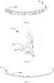
- the contact detection electrode 200 includes a flexible substrate 291.
- the positive and negative electrodes of the contact detection electrode 200 are mounted on the flexible substrate 291.
- the flexible substrate 291 is wound and mounted on the peripheral side wall of the housing 110.
- the flexible substrate 291 is configured in an elongate-strip shape.
- the positive and negative electrodes are arranged sequentially in a staggered manner on the surface of the flexible substrate 291, and there are gaps between the positive electrodes and the negative electrodes.
- a lower side of the flexible substrate 291 is provided adjacent to the chassis 120, so that the positive electrodes and the negative electrodes are more close to the ground, thereby facilitating the detection by the contact detection electrode 200.
- the positive electrode includes a plurality of positive electrode plates
- the negative electrode includes a plurality of negative electrode plates 293.
- the positive electrode plates and the negative electrode plates 293 are arranged sequentially in a staggered manner on the flexible substrate 291.
- ends of all the positive electrode plates 292 are connected together by a conductive connector.
- ends of all the negative electrode plates 293 are connected together by a conductive connector.
- the connector connecting the positive electrode plates 292 and the connector connecting the negative electrode plates 293 are respectively located on two opposite sides of the flexible insulating substrate.
- the positive electrode plates 292 and the negative electrode plates 293 extend along a length direction of the flexible substrate 291, or along a width direction of the flexible substrate 291. That is, the positive electrode plates 292 can extend along the length direction of the flexible substrate 291 or along the width direction of the flexible substrate 291.
- the negative electrode plates 293 and the positive electrode plates 292 are arranged in parallel. That is, the negative electrode plates 293 can extend along the length direction of the flexible substrate 291 or along the width direction of the flexible substrate 291.
- the positive electrode plates 292 and/or the negative electrode plates 293 are attached and fixed to the surface of the flexible substrate 291.
- attaching and fixing for example, by glue or by slot fitting.
- an end of the positive electrode plates and/or the negative electrode plates is connected to the surface of the flexible substrate 291, and the other end thereof extends in a direction away from the flexible substrate 291.
- the positive electrode plates 292 and/or the negative electrode plates 293 extend toward an end away from the flexible substrate 291, so that a deeper detection area is formed between the adjacent positive electrode plates 292 and the negative electrode plates 293.
- a height of the detection area (a distance from the chassis 120 or a distance from the ground) is equivalent to a height of the flexible substrate 291. In this way, the contact detection electrode 200 can increase the area of contact between the dirt and the electrode during the detection process, thereby effectively improving the detection accuracy.
- the flexible substrate 291 is mounted on a lower portion of the peripheral side wall of the housing 110, and the positive electrode plates and/or the negative electrode plates extend toward the bottom portion of the housing 110.
- the flexible substrate 291 By mounting the flexible substrate 291 on the lower portion of the peripheral side wall and configuring the positive electrode plates 292 and/or the negative electrode plates 293 to extend toward the bottom portion, a detection area enclosed by the positive electrode plates 292 and the negative electrode plates 293 is made more close to the chassis 120 or the bottom surface, such that the area of contact with the dirt during the detection process is further increased, thereby efficiently improving the detection accuracy.
- the positive electrode includes positive electrode bumps 294, and the negative electrode includes negative electrode bumps 295.
- the positive electrode bumps 294 and the negative electrode bumps 295 are arranged sequentially in a dot matrix.
- the dot matrix is arranged on the surface of the flexible substrate 291. Since the areas of the positive convex points 294 and the negative convex points 295 are small, they can be set very flexibly as required, so that the detection area can also be formed very flexibly, which is conducive to improving the adaptability of the electrode 200.
Landscapes
- Engineering & Computer Science (AREA)
- Chemical & Material Sciences (AREA)
- Mechanical Engineering (AREA)
- Immunology (AREA)
- Electrochemistry (AREA)
- Life Sciences & Earth Sciences (AREA)
- Analytical Chemistry (AREA)
- Biochemistry (AREA)
- General Health & Medical Sciences (AREA)
- General Physics & Mathematics (AREA)
- Physics & Mathematics (AREA)
- Pathology (AREA)
- Health & Medical Sciences (AREA)
- Robotics (AREA)
- Chemical Kinetics & Catalysis (AREA)
- Investigating Or Analyzing Materials By The Use Of Electric Means (AREA)
- Measurement Of Length, Angles, Or The Like Using Electric Or Magnetic Means (AREA)
- Electric Vacuum Cleaner (AREA)
- Telephone Set Structure (AREA)
- Force Measurement Appropriate To Specific Purposes (AREA)
Abstract
Description
- The present disclosure relates to the technical field of cleaning, and particularly to a movable electric device.
- When detecting pet excrements, sweeping robots typically use non-contact sensors such as infrared sensors and odor sensors. Since the sensors do not directly contact the excrements, detection of the excrements is rendered inaccurate, which is not conducive for the sweeping machine to make an accurate judgment of the detection results.
- A main object of the present disclosure is to provide a movable electric device, for improving an accuracy with which the movable electric device detects diffusible dirt.
- In order to achieve the above-mentioned object, the movable electric device provided by the present disclosure is configured to detect or clean up wastes. The movable electric device includes a movable device body and a contact detection electrode. The movable device body has an electric drive means. The contact detection electrode is mounted on the movable device body. In response to the contact detection electrode contacting diffusible dirt, a resistance, capacitance or impedance of the contact detection electrode varies.
- Preferably, the contact detection electrode includes a ring-shaped positive electrode and a ring-shaped negative electrode. The ring-shaped negative electrode is provided to sleeve an outer side of the ring-shaped positive electrode or provided inside the ring-shaped positive electrode. A detection area is formed between the ring-shaped positive electrode and the ring-shaped negative electrode.
- Preferably, the contact detection electrode includes a comb-teeth positive electrode and a comb-teeth negative electrode. The comb-teeth positive electrode includes a positive electrode connecting arm and a plurality of positive electrode teeth arranged along a length direction of the positive electrode connecting arm. The comb-teeth negative electrode includes a negative electrode connecting arm and a plurality of negative electrode teeth arranged along a length direction of the negative electrode connecting arm. The positive electrode teeth and the negative electrode teeth are arranged in a staggered manner to form a detection area between the positive electrode teeth and the negative electrode teeth.
- Preferably, the contact detection electrode includes a curvilinear positive electrode and a curvilinear negative electrode. The curvilinear positive electrode bends and extends along a direction. The curvilinear negative electrode extends along a length direction of the curvilinear positive electrode to form a detection area between the curvilinear positive electrode and the curvilinear negative electrode.
- Preferably, the curvilinear positive electrode extends in the form of one or more of a sine curve, a cosine curve, a normal distribution curve, a parabola, a wave polyline, and a square wave curve. Or the curvilinear negative electrode extends in the form of one or more of a sine curve, a cosine curve, a normal distribution curve, a parabola, a wave broken line, and a square wave curve.
- Preferably, the contact detection electrode includes a plurality of positive and negative electrode points arranged in a staggered manner. A detection area is formed between the positive electrode points and the negative electrode points.
- Preferably, the contact detection electrode includes a plurality of positive electrode plates and a plurality of negative electrodes. The plurality of positive electrode plates are arranged radially from the center to the periphery. The plurality of negative electrodes are located in gaps between adjacent positive electrode plates. A detection area is formed between the positive electrode plates and the negative electrodes.
- The contact detection electrode includes a plurality of negative electrode plates and a plurality of positive electrodes. The plurality of negative electrode plates are arranged radially from the center to the periphery. The plurality of positive electrodes are located in gaps between adjacent negative electrode plates. A detection area is formed between the negative electrode plates and the positive electrodes.
- Preferably, when the positive electrode plates are arranged radially, the negative electrodes are arranged in a circle with a radiation center of the positive electrode plates as a center of the circle. When the negative electrode plates are arranged radially, the positive electrodes are arranged in a circle with a radiation center of the negative electrode plates as a center of the circle.
- Preferably, the contact detection electrode includes a central positive electrode and a plurality of negative electrodes arranged circumferentially around the central positive electrode. A detection area is formed between the central positive electrode and the negative electrodes. Or the contact detection electrode includes a central negative electrode and a plurality of positive electrodes arranged circumferentially around the central negative electrode. The detection area is formed between the central negative electrode and the positive electrodes.
- Preferably, the contact detection electrode includes a positive electrode and a negative electrode. A thickness of the positive electrode is greater than a thickness of the negative electrode, or the thickness of the negative electrode is greater than the thickness of the positive electrode.
- Preferably, the contact detection electrode includes a positive electrode and a negative electrode. The positive electrode and/or the negative electrode have pointed teeth. Or the positive electrode and/or the negative electrode have arc-shaped transitions.
- Preferably, there are multiple groups of contact detection electrodes. A thickness of at least one group of the contact detection electrodes is greater than a thickness of the other contact detection electrodes.
- Preferably, the contact detection electrode includes a positive electrode and a negative electrode. The positive electrode and the negative electrode have a flexibility and a length of the positive electrode and a length of the negative electrode are smaller than half of a distance between adjacent positive and negative electrodes.
- Preferably, the movable device body includes a housing and a roller provided at a bottom portion of the housing. The contact detection electrode is provided on an outer peripheral surface and/or side portion of the roller.
- Preferably, the contact detection electrode includes a positive electrode and a negative electrode. The positive electrode includes a plurality of positive electrode plates connected by a connector. A positive electrode gap is provided between two adjacent positive electrode plates. The negative electrode includes a plurality of negative electrode plates connected by a connector. A negative electrode gap is provided between two adjacent negative electrode plates. The positive electrode and the negative electrode are arranged in parallel. Further, the positive electrode plates are configured to correspond to the negative electrode gaps, and the negative electrode plates are configured to correspond to the positive electrode gaps.
- Preferably, the positive electrode and the negative electrode are arranged in a ring shape, and surround the outer peripheral surface of the roller along a peripheral direction of the roller.
- Preferably, the movable device body includes a first baffle provided on a axial side of the roller. The contact detection electrode is provided on the first baffle.
- Preferably, the contact detection electrode is mounted at a bottom portion of the first baffle.
- Preferably, the contact detection electrode includes a positive electrode and a negative electrode. The positive electrode and/or the negative electrode are/is mounted on a side of the first baffle facing the roller, and the negative electrode and/or the positive electrode are mounted on a side of the roller facing the first baffle.
- Preferably, a rotating shaft of the roller is rotatably connected to the first baffle.
- Preferably, a peripheral side wall of the roller is provided with a mounting cavity. The contact detection electrode is mounted in the mounting cavity. A top portion of the contact detection electrode is flush with an opening of the mounting cavity or lower than an edge of the opening.
- Preferably, the movable device body includes a second baffle provided on an upper portion of the roller. The contact detection electrode is mounted on the second baffle.
- Preferably, the contact detection electrode includes a positive electrode and a negative electrode. The positive electrode and/or the negative electrode are mounted on the second baffle; and the negative electrode and/or the positive electrode are mounted on the roller.
- Preferably, there are multiple groups of contact detection electrodes. Groups of the contact detection electrodes are distributed on multiple positions of the movable device body.
- Preferably, the movable device body includes a chassis. The contact detection electrode is provided on the chassis.
- Preferably, the contact detection electrode includes an insulating substrate, and a positive electrode and a negative electrode both mounted on the insulating substrate. A detection area is formed between the positive electrode and the negative electrode.
- Preferably, the contact detection electrode includes a fixing part and a detecting part connected to the fixing part. The fixing part is detachably connected to the chassis. The detecting part extends in a direction away from the fixing part.
- Preferably, the contact detection electrode is configured in an elongate-strip shape, and extends along a peripheral direction of the chassis.
- Preferably, the contact detection electrode is provided in proximity to an edge of a front side of the chassis.
- Preferably, the movable device body includes a side brush. A mounting platform of the side brush protrudes outward. The contact detection electrode is provided on the mounting platform.
- Preferably, the number of side brushes is two. The two side brushes are provided on a left side and a right side of a front side of the bottom portion of the housing respectively. The contact detection electrode is mounted on a side of the mounting platform facing the middle.
- Preferably, the contact detection electrodes are mounted on the side brushes.
- Preferably, the movable device body includes a rolling brush provided in the middle of the housing. The contact detection electrode is mounted on the rolling brush.
- Preferably, the contact detection electrode is a flexible electrode. The contact detection electrode is arranged in parallel with bristles of the rolling brush.
- Preferably, the movable device body includes a housing. The contact detection electrode is provided on a peripheral side wall of the housing.
- Preferably, the contact detection electrode includes a flexible substrate. The positive electrode and the negative electrode of the contact detection electrode are mounted on the flexible substrate. The flexible substrate is wound and mounted on the peripheral side wall of the housing.
- Preferably, the positive electrode includes a plurality of positive electrode plates. The negative electrode includes a plurality of negative electrode plates. The positive electrode plates and the negative electrode plates are arranged sequentially in a staggered manner on the flexible substrate.
- Preferably, the positive electrode plates and the negative electrode plates extend along a length direction of the flexible substrate or along a width direction of the flexible substrate.
- Preferably, the positive electrode plates and/or the negative electrode plates are attached and fixed to a surface of the flexible substrate.
- Preferably, an end of each of the positive electrode plates and/or the negative electrode plates is connected to the surface of the flexible substrate, and the other end thereof extends in a direction away from the flexible substrate.
- Preferably, the flexible substrate is mounted on a lower portion of the peripheral side wall of the housing. The positive electrode plates and/or the negative electrode plates extend towards the bottom portion of the housing.
- Preferably, the positive electrode includes positive electrode bumps, and the negative electrode includes negative electrode bumps. The positive electrode bumps and the negative electrode bumps are arranged sequentially in a dot matrix. The dot matrix is arranged on the surface of the flexible substrate.
- Preferably, the movable electric device is a movable detection device or a movable cleaning device.
- According to technical solutions of the present disclosure, during movement of the movable electric device, after an object comes into contact with the contact detection electrode and enters the detection area of the contact detection electrode, a capacitance value, resistance value or impedance value of the contact detection electrode varies, so that current in a detection circuit where the contact detection electrode lies varies. According to the variation in the capacitance value, resistance value or impedance value of the contact detection electrode, or the variation in the current in the detection circuit, it is judged whether the currently detected object is diffusible dirt. Since the contact detection electrode directly contacts the object for detection, numerous factors that affect the detection accuracy are accordingly avoided. Thus the accuracy of the detection results is greatly improved, thereby facilitating improvement of an accuracy with which the movable electric device detects the diffusible dirt and facilitating an accurate judgment and operation of the movable electric device.
- In order to explain the technical solutions in embodiments of the present disclosure or the prior art more clearly, drawings required to be used in the description of the embodiments or the prior art will be briefly introduced. Evidently, the drawings in the following description are merely some of the embodiments of the present disclosure. According to the structures shown in these drawings, other drawings may be further obtained by those ordinarily skilled in the art without expending inventive labor.
-
FIG 1 is a schematic structural diagram of an embodiment of a movable electric device according to the present disclosure. -
FIG 2 is a schematic structural diagram of a bottom perspective ofFIG 1 . -
FIG 3 is a partially enlarged diagram of a location A inFIG 2 . -
FIG. 4 is a schematic structural diagram of an embodiment of a contact detection electrode of a movable electric device according to the present disclosure. -
FIG. 5 is a schematic structural diagram of another embodiment of a contact detection electrode of a movable electric device according to the present disclosure. -
FIG. 6 is a schematic structural diagram of yet another embodiment of a contact detection electrode of a movable electric device according to the present disclosure; -
FIG. 7 is a schematic structural diagram of still another embodiment of a contact detection electrode of a movable electric device according to the present disclosure. -
FIG. 8 is a schematic structural diagram of still another embodiment of a contact detection electrode of a movable electric device according to the present disclosure. -
FIG. 9 is a schematic structural diagram of still another embodiment of a contact detection electrode of a movable electric device according to the present disclosure. -
FIG. 10 is a schematic structural diagram of still another embodiment of a contact detection electrode of a movable electric device according to the present disclosure. -
FIG. 11 is a schematic structural diagram of a roller of a movable electric device according to the present disclosure. -
FIG. 12 is a schematic structural diagram of a contact detection electrode mounted on a roller of a movable electric device according to the present disclosure. -
FIGS. 13 to 14 are schematic structural diagrams of a contact detection electrode mounted on a chassis of a movable electric device according to the present disclosure. -
FIGS. 15-22 are schematic structural diagrams of a contact detection electrode mounted on a housing of a movable electric device according to the present disclosure. -
FIG. 16 is a partially enlarged diagram of a location B inFIG. 15 . -
FIG. 18 is a partially enlarged view of a location C inFIG. 17 . -
FIG. 20 is a partially enlarged view of a location D inFIG. 19 . -
FIG. 22 is a partially enlarged view of a location E inFIG. 21 . -
FIG. 23 is a schematic structural diagram of an embodiment of a contact detection electrode. -
FIG. 24 is a schematic structural diagram of a roller and a first baffle. - Realization of the object, the functional characteristics and the advantages of the present disclosure will be further described in conjunction with the embodiments and with reference to the accompanying drawings.
- The technical solutions in the embodiments of the present disclosure will be clearly and completely described below in conjunction with the accompanying drawings in the embodiments of the present disclosure. Obviously, the described embodiments are only a part of the embodiments of the present disclosure, rather than all the embodiments. All other embodiments obtained by those ordinarily skilled in the art based on the embodiments of the present disclosure, without expending inventive labor, shall fall within the protection scope of the present disclosure.
- It should be noted that, all the directional indications (such as up, down, left, right, front, back...) in the embodiments of the present disclosure are only used to explain relative position relationships, movement conditions and the like between various components in a specific posture (as shown in the accompanying drawings). If the specific posture varies, the directional indications will change accordingly.
- Furthermore, the descriptions related to "first", "second", and the like in the present disclosure are only used for descriptive purposes, and shall not be construed as indicating or implying their relative importance or implicitly indicating the number of indicated technical features. Therefore, the features defined with "first" and "second" may explicitly or implicitly include at least one of these features. In addition, the technical solutions between various embodiments may be combined with each other, which yet must be on the premise that those ordinarily skilled in the art may carry out the combination of the technical solutions. When the combination of the technical solutions involves a contradiction or cannot be carried out, it should be considered that such a combination of the technical solutions does not exist, and does not fall within the protection scope claimed by the present disclosure.
- The present disclosure mainly proposes a movable electric device. The movable electric device can be a movable cleaning device such as a sweeping robot (with detecting and cleaning functions at the same time), or an electric detection device with only a detecting function. The movable electric device has a contact detection electrode. The contact detection electrode has a detection area. In response to that the contact detection electrode comes into contact with diffusible dirt, one of a resistance value, capacitance value and impedance value of the contact detection electrode varies, so that current in a detection circuit of the movable electric device varies. A control circuit of the movable electric device triggers a prompt apparatus of the movable electric device according to the variation in the resistance value, capacitance value or impedance value of the contact detection electrode, or according to the variation in the current value (or the value of current) in the detection circuit. The prompt apparatus may send out an alert to the outside via one or more of light, sound and vibration. Of course, in some embodiments, the prompt apparatus may also send a signal to a designated terminal and send a prompt through this terminal.
- Of course, if the movable electric device itself has the function of cleaning up diffusible dirt, the movable electric device switches the cleaning device to a cleaning tool for diffusible dirt to remove the diffusible dirt. When the movable electric device itself does not have the function of cleaning up diffusible dirt, the movable electric device stops moving to avoid diffusion of the dirt and contaminating the ground to be cleaned. It is worth noting that, diffusible dirt usually has a certain humidity and viscosity, and is prone to diffuse along with carriers, such as animal excrements, melted candies, liquids (e.g., water), flowable media (e.g., tomato sauce, soup) and the like.
- The specific structure of the movable electric device will be mainly described below.
- With reference to
FIGS. 1 to 3 , in the embodiments of the present disclosure, a movable electric device is configured to detect or clean up wastes. The movable electric device has amovable device body 100 including an electric drive means or an electric actuator. The electric drive means may be a motor, an electrically driven hydraulic pump or pneumatic pump, electromagnetic-induction drive equipment, or any other devices driven by electricity. The movable electric device further includes acontact detection electrode 200 which is mounted on themovable device body 100. In response to thecontact detection electrode 200 contacting diffusible dirt, a resistance, capacitance, or impedance of thecontact detection electrode 200 varies. - The
movable device body 100 includes ahousing 110 and aroller 130 or awheel 130. Theroller 130 is disposed at a bottom portion of thehousing 110 and is rotatably connected to thehousing 110. The electric drive means is connected to theroller 130 to drive theroller 130 to roll. The electric drive means is connected to thehousing 110. Thehousing 110 can have many shapes, such as polygon, ellipse, circle, etc. In the case of a same volume, in order to enable the movable electric device to enter a narrower space, thehousing 110 is configured to be circular. In order to prevent external environmental factors from affecting the rolling of theroller 130, afirst baffle 170 is provided on a side of theroller 130 in an axial direction of theroller 130, and asecond baffle 160 is provided on a top portion of theroller 130. A bottom portion of thehousing 110 is provided with a chassis 120 (thechassis 120 does not belong to the housing 110), or the bottom portion of thehousing 110 is thechassis 120, that is, thechassis 120 is a part of thehousing 110. - A rolling
brush 150 for cleaning up ground dusts and the like is mounted on thehousing 110, and is driven by a motor. In the present embodiment, aside brush 140 is also provided on thechassis 120. Theside brush 140 extends from thechassis 120 out of thehousing 110 to expand the cleaning range of the movable electric device, thereby improving the cleaning efficiency. - In the present embodiment, during the movement of the movable electric device, after an object contacts the
contact detection electrode 200 and enters a detection area of thecontact detection electrode 200, a capacitance value, resistance value or impedance value of thecontact detection electrode 200 varies, so that current in the detection circuit where thecontact detection electrode 200 lies varies. According to the variation in the capacitance value, resistant value or impedance value of thecontact detection electrode 200 or the variation in the current in the detection circuit, it is judged whether the currently detected object is diffusible dirt. Since thecontact detection electrode 200 directly contacts the object for detection, numerous factors that affect the detection accuracy are accordingly avoided, so that the accuracy of the detection results is greatly improved, thereby facilitating the improvement of an accuracy with which the movable electric device detects the diffusible dirt and facilitating an accurate judgment and operation of the movable electric device. - It is worth noting that, judging whether the currently detected object is diffusible dirt according to the capacitance value, resistance value, impedance value or current value can be achieved by a comparison circuit. For example, a preset capacitance value is configured; and when the detected capacitance value is greater than or equal to the preset capacitance value, the current object is judged to be diffusible dirt, and when the detected capacitance value is smaller than the preset capacitance value, the current object is judged to be non-diffusible dirt. Said judging whether the currently detected object is diffusible dirt according to the capacitance value, resistance value, impedance value or current value can also be realized by software. For example, the detected capacitance value may be compared with a capacitance value pre-stored in a memory of the movable electric device. Different capacitance values that are stored correspond to different types of objects. One or more of the objects are certainly diffusing dirt.
- The
contact detection electrode 200 may be provided in any of such positions as a peripheral side wall of thehousing 110, thechassis 120, theroller 130, thefirst baffle 170, thesecond baffle 160, theside brush 140, and the rollingbrush 150 etc. Some specific forms of thecontact detection electrode 200, specific positions where thecontact detection electrode 200 is arranged, preferred electrode forms at the specific positions, and the like will be specifically introduced below. - Firstly, specific structures of several
contact detection electrodes 200 are introduced. - With reference to 4, a ring-shaped
contact detection electrode 200 is shown. Thecontact detection electrode 200 includes a ring-shapedpositive electrode 211 and a ring-shapednegative electrode 212. The ring-shapednegative electrode 212 is sleeved at an outer side of the ring-shapedpositive electrode 211. Alternatively, the ring-shapednegative electrode 212 is disposed inside the ring-shapedpositive electrode 211. A detection area is formed between the ring-shapedpositive electrode 211 and the ring-shapednegative electrode 212. - Specifically, in the present embodiment, the ring-shaped
positive electrode 211 is configured to be in a ring shape. Multiple ring shapes may be adopted. For example, the ring-shapedpositive electrode 211 is configured in a circle, an ellipse, a triangle, a square, or other polygon. The ring shape herein can be a complete closed ring, and can also be a ring with a small-sized opening. That is, the ring shape describes an extending tendency of the electrode. Likewise, the ring-shapednegative electrode 212 is also configured to be in a ring shape; and its shape can be a circle, an ellipse, a triangle, a quadrangle, or the like. The shape of the ring-shapednegative electrode 212 can be equivalent to that of the ring-shapedpositive electrode 211, or can be completely different therefrom. The ring-shapednegative electrode 212 may be configured to be sleeved at the outside of the ring-shapedpositive electrode 211, or may be mounted within an area enclosed by the ring-shapedpositive electrode 211. A separation area is provided between the ring-shapedpositive electrode 211 and the ring-shapednegative electrode 212. The separation area functions as a detection area of the contact electrode. When an object enters the detection area, a resistance, capacitance or impedance of thecontact detection electrode 200 varies. The main control circuit of the movable electric device acquires the parameter variation, and judges whether the object is diffusible dirt according to the variation. - With reference to
FIG. 5 , a comb-teeth shaped electrode is shown. Thecontact detection electrode 200 includes a comb-teethpositive electrode 251 and a comb-toothnegative electrode 254. The comb-teethpositive electrode 251 includes a positiveelectrode connecting arm 252 and a plurality ofpositive electrode teeth 253 arranged along a length direction of the positiveelectrode connecting arm 252. - The comb-tooth
negative electrode 254 includes a negativeelectrode connecting arm 256 and a plurality ofnegative electrode teeth 255 arranged along a length direction of the negativeelectrode connecting arm 256. - The
positive electrode teeth 253 and thenegative electrode teeth 255 are arranged in a staggered manner to form a detection area between thepositive electrode teeth 253 and thenegative electrode teeth 255. - The
positive electrode teeth 253 of the comb-teethpositive electrode 251 are configured in an elongate-strip shape. One end of thepositive electrode teeth 253 is connected to the positiveelectrode connecting arm 252, and the other end thereof extends in a direction away from the positiveelectrode connecting arm 252. Thepositive electrode teeth 253 and the connecting arm are configured at an included angle between 30° and 150°. Thepositive electrode teeth 253 and the positiveelectrode connecting arm 252 being perpendicular to each other is taken as an example. Thepositive electrode teeth 253 can be arranged on a same side of the positiveelectrode connecting arm 252 or on two opposite sides of the connectingarm 252. Of course, in some embodiments, thepositive electrode teeth 253 may also be arranged along a peripheral direction of the connecting arm. Thepositive electrode teeth 253 and the positiveelectrode connecting arm 252 may be configured integrally or separately. - Similarly, the
negative electrode teeth 255 of the comb-teethnegative electrode 254 are configured in an elongate-strip shape. One end of thenegative electrode teeth 255 is connected to the negativeelectrode connecting arm 256, and the other end thereof extends in a direction away from the negativeelectrode connecting arm 252. Thenegative electrode teeth 253 and the connecting arm are configured at an included angle between 30° and 150°. Thenegative electrode teeth 253 and the negativeelectrode connecting arm 256 being perpendicular to each other is taken as an example. Thenegative electrode teeth 255 can be arranged on a same side of the negativeelectrode connecting arm 256 or on two opposite sides of the connecting arm. Of course, in some embodiments, thenegative electrode teeth 252 may also be arranged along a peripheral direction of the negativeelectrode connecting arm 256. Thenegative electrode teeth 255 and the negativeelectrode connecting arm 256 may be configured integrally or separately. - The positive
electrode connecting arm 252 and the negativeelectrode connecting arm 256 are configured in parallel. Thepositive electrode teeth 253 extend toward the negativeelectrode connecting arm 256. Thenegative electrode teeth 255 extend toward the positiveelectrode connecting arm 252. Thepositive electrode teeth 253 and thenegative electrode teeth 255 are arranged in a spaced and staggered manner. A detection area is formed between thepositive electrode teeth 253 and thenegative electrode teeth 255. When thepositive electrode teeth 253 or thenegative electrode teeth 255 are arranged in multiple directions of the positiveelectrode connecting arm 252 and the negativeelectrode connecting arm 256, a comb-teethpositive electrode 251 mates with a plurality of comb-teethnegative electrodes 254, and a comb-teethnegative electrode 254 mates with a plurality of comb-teethpositive electrodes 251. - With reference to
FIG. 6 , a curvilinear electrode is shown. Thecontact detection electrode 200 includes a curvilinearpositive electrode 222 and a curvilinearnegative electrode 221. The curvilinearpositive electrode 222 bends and extends in a direction. The curvilinearnegative electrode 221 extends along a length direction of the curvilinearpositive electrode 222 to form a detection area between the curvilinearpositive electrode 222 and the curvilinearnegative electrode 221. - Specifically, in the present embodiment, the curvilinear
positive electrode 222 is configured in a curved linear shape, and its extending direction can be configured according to actual demand. That is, the extending direction of the curvilinearpositive electrode 222 can be in the shape of a preset equation curve, such as a sine curve, a cosine curve, a parabola, a normal distribution curve, or the like. The curvilinearpositive electrode 222 may also extend in a square wave, and can also be configured in a wave-folded line or a wave polyline. Likewise, the curvilinearnegative electrode 221 is configured in a curved linear shape, and its extending direction can be configured according to actual demand. That is, the extending direction of curvilinearnegative electrode 221 can be in the shape of a preset equation curve, such as a sine curve, a cosine curve, a parabola, a normal distribution curve, or the like. The curvilinearnegative electrode 221 may also extend in a square wave, and can also be configured in a wave-folded line. Specifically, the curvilinearpositive electrode 222 extends in the form of one or more of a sine curve, a cosine curve, and a square wave curve, and/or the curvilinearnegative electrode 221 extends in the form of one or more of a sine curve, a cosine curve, and a square wave curve. The curvilinearpositive electrode 222 and the curvilinearnegative electrode 221 are configured in parallel, and a detection area is enclosed and formed between the curvilinearpositive electrode 222 and the curvilinearnegative electrode 221. The shape of the curvilinearpositive electrode 222 and the shape of the curvilinearnegative electrode 221 can be identical or different. The shapes of the curvilinearpositive electrode 222 and the curvilinearnegative electrode 221 being identical is taken as an example. - With reference to
FIG. 7 , a dot matrix electrode is shown. Thecontact detection electrode 200 includes a plurality ofpositive electrode points 231 and negative electrode points 232. Thepositive electrode points 231 and thenegative electrode points 232 are arranged in a staggered manner. A detection area is formed between thepositive electrode points 231 and the negative electrode points 232. - Specifically, in the present embodiment, the positive electrode and the negative electrode of the
contact detection electrode 200 are arranged in a dot shape. A plurality ofpositive electrode points 231 andnegative electrode points 232 may be arranged in a desired shape, for example, a straight line, a curve, a circle, an ellipse, a polygon (a triangle, a rhombus, etc.), or the like, according to actual operating conditions. Thepositive electrode points 231 and thenegative electrode points 232 have such small volumes that a shape in which thepositive electrode points 231 and thenegative electrode points 232 are arranged may perfectly fit with the actually desired shape. As such, thecontact detection electrode 200 may not only be arranged at any desired position to improve adaptability of thecontact detection electrode 200, but also may detect positions which can hardly be detected by ordinary electrodes, thereby increasing the detection range of thecontact detection electrode 200. - With reference to
FIGS. 9 and10 , a star-shaped radial shape is shown. Thecontact detection electrode 200 includes a plurality ofpositive electrode plates 281 and a plurality ofnegative electrodes 282. The plurality ofpositive electrode plates 281 are arranged radially from the center to the periphery. The plurality ofnegative electrodes 282 are located in gaps between adjacentpositive electrode plates 281. A detection area is formed between thepositive electrode plates 281 and thenegative electrodes 282. - Alternatively, the
contact detection electrode 200 includes a plurality ofnegative electrode 282 plates and a plurality of positive electrodes. The plurality ofnegative electrode 282 plates are arranged radially from the center to the periphery. The plurality of positive electrodes are located in gaps between the adjacentnegative electrode 282 plates. A detection area is formed between thenegative electrode 282 plates and the positive electrodes. - Specifically, in the present embodiment, the
positive electrode plates 281 are configured in an elongate-strip shape which can be any of an elongate rectangle, trapezoid, triangle, and the like. An end of each of the plurality ofpositive electrode plates 281 extends toward a same convergence point, and the other end thereof extends radially in a direction away from the convergence point. Ends of thepositive electrode plates 281 adjacent to the convergence point may be connected or not connected. The connection of ends of thepositive electrode plates 281 adjacent to the convergence point as an example facilitates power supply to all thepositive electrode plates 281 at the same time. There is a gap between the ends of two adjacentpositive electrode plates 281 away from the convergence point. The gap may be a uniform gap or a gradual gap. - The
negative electrodes 282 can have a variety of forms, such as an elongate-strip shape, a block shape, a dot shape, etc.. When thenegative electrodes 282 are in the elongate-strip shape, thenegative electrodes 282 extend along a length direction of the gap. When thenegative electrodes 282 are in the block shape and the dot shape, thenegative electrodes 282 are arranged in the gap. A plurality ofnegative electrodes 282 may be provided in a same gap. In some embodiments, ends of a plurality ofpositive electrode plates 281 adjacent to the convergence point enclose a central area in which thenegative electrodes 282 are provided. - It is worth noting that, in some embodiments, the
negative electrodes 282 are arranged radially in a star shape, and the positive electrodes are embedded in the gaps between the adjacentnegative electrodes 282. - In order to improve the detection efficiency and detection accuracy of the
contact detection electrode 200, when thepositive electrode plates 281 are arranged radially, thenegative electrodes 282 are arranged in a circle with a radiation center of thepositive electrode plates 281 as a center of the circle,. - When the
negative electrodes 282 plates are arranged radially, the positive electrodes are arranged in a circle with a radiation center of thenegative electrodes 282 plates as a center of the circle. - With the radial arrangement of the
positive electrode plates 281 as an example, thenegative electrodes 282 are arranged in the gaps between the adjacent positive electrodes, and thenegative electrodes 282 in different gaps are arranged in a ring shape. The convergence point is the center of the ring shape. As such, thenegative electrodes 282 are arranged in such a regular and reasonable manner that the detection area between thenegative electrodes 282 and the positive electrode plates has a moderate area, thereby guaranteeing accurate detection of the contact electrode and an effective area of the detection area. - With reference to
FIG. 8 , a central electrode is shown. Thecontact detection electrode 200 includes a centralpositive electrode 241 and a plurality ofnegative electrodes 242 arranged circumferentially around the centralpositive electrode 241. A detection area is formed between the centralpositive electrode 241 and thenegative electrodes 242. Or thecontact detection electrode 200 includes a centralnegative electrode 242 and a plurality of positive electrodes arranged circumferentially around the centralnegative electrode 242. A detection area is formed between the centralnegative electrode 242 and the positive electrodes. - Specifically, in the present embodiment, the central
positive electrode 241 is located in the middle, and thenegative electrodes 242 are provided around the middle. The number ofnegative electrodes 242 may be one or plural. A plurality ofnegative electrodes 242 are arranged surrounding the centralpositive electrode 241. The number ofnegative electrodes 242 is related to the area of the positive electrode. The larger the area facing thenegative electrodes 242, the greater the number ofnegative electrodes 242 that can be matched with thepositive electrode 241 at the same time. Thenegative electrodes 242 radiate to a periphery of the centralpositive electrode 241, with the centralpositive electrode 241 as the center. The shapes of the centralpositive electrode 241 and thenegative electrodes 242 are not limited herein, and they can be any of a triangle, a quadrilateral and other polygon, a circle, an ellipse, and the like. Of course, in some embodiments, positive electrodes may also be arranged on the periphery of the centralpositive electrode 241, and cooperate with the adjacentnegative electrodes 242 to form a detection area. - In some other embodiments, the
negative electrode 242 is placed in the middle to form the centralnegative electrode 242 around which positive electrodes are provided. The number of positive electrodes can be one or plural, and the plurality of positive electrodes are arranged around the centralnegative electrode 242. The number of positive electrodes is related to the area of thenegative electrode 242. The larger the area facing the positive electrodes, the greater the number of positive electrodes that can be matched with thenegative electrode 242 at the same time. Thepositive electrodes 242 radiate to a periphery of the centralnegative electrode 242, with the centralnegative electrode 242 as the center. The shapes of the centralnegative electrode 242 and the positive electrodes are not limited herein, and they can be any of a triangle, a quadrilateral and other polygon, a circle, an ellipse, and the like. Of course, in some embodiments,negative electrodes 242 may also be arranged on the periphery of the centralnegative electrode 242, and cooperate with the adjacent positive electrodes to form a detection area. - In order to improve the adaptability of the contact electrode, the
contact detection electrode 200 includes a positive electrode and a negative electrode. A thickness of the positive electrode is greater than that of the negative electrode. Alternatively, the thickness of the negative electrode is greater than that of the positive electrode. - In the present embodiment, when the
contact detection electrode 200 is mounted on themovable device body 100, contour surfaces of some mounting positions are uneven, thus after the electrode is mounted, an end of the electrode away from themovable device body 100 is uneven, resulting in a low detection accuracy (there is a case when only a single electrode contacts the detected object). In this case, it is needed to adjust the thickness of the electrode to compensate for the detection accuracy problem caused by the unevenness of the contour surfaces. A positive electrode or a negative electrode with a relatively small thickness is correspondingly adopted for a convex contour surface, and a negative electrode or a positive electrode with a relatively great thickness is adopted for a concave contour surface, so that ends of the paired positive electrode and negative electrode away from themovable device body 100 are flush with each other. - In order to improve the detection effect of the
contact detection electrode 200 or prolong its service life, thecontact detection electrode 200 includes a positive electrode and a negative electrode. The positive electrode and/or the negative electrode have pointed teeth or sharp teeth. Alternatively, the positive electrode and/or the negative electrode have arc-shaped transitions. - When the positive electrode or the negative electrode has pointed teeth, the pointed teeth are more likely to adhere to the dirt to be detected, which is conducive to improving the detection accuracy. There are many shapes with pointed teeth, such as a triangle, a trapezoid, and the like. When the positive electrode or the negative electrode has an arc-shaped transition, it is possible to prevent the electrode from being scratched during the detection process. The arc shape of the arc-shaped transition can have various forms, for example, a circular arc.
- In order to adapt to different working environments, there are multiple groups of
contact detection electrodes 200, where at least one group of thecontact detection electrodes 200 has a thickness greater than that of the othercontact detection electrodes 200. Thicknesses of the multiple groups ofcontact detection electrodes 200 may all be different, or some of them may be identical. Thecontact detection electrodes 200 of different thicknesses are mounted on themovable device body 100 according to requirements of different operating conditions. In some embodiments, thecontact detection electrodes 200 are arranged such that the thickness thereof gradually increases along an extending direction from the edge to the middle of themovable device body 100. The movable electric device can thus detect contaminants in different situations, which is conducive to improving the adaptability of thecontact detection electrode 200. - In some embodiments, in order to extend the service life of the
contact detection electrode 200, thecontact detection electrode 200 is configured as a flexible electrode. Thecontact detection electrode 200 includes a positive electrode and a negative electrode. The positive electrode and the negative electrode have flexibility. A length of the positive electrode and a length of the negative electrode are smaller than a half of the distance between the adjacent positive electrode and negative electrode. During the process of detecting dirt, if the flexible electrode collides with a rigid object, its shape will be elastically deformed. After the collision ends, the electrode will restore to its original shape under the action of an elastic restoring force. This process will repeat. Since thecontact detection electrode 200 is flexible, it would not be easily damaged, thereby facilitating the extension of its service life. - The
contact detection electrodes 200 mounted in different positions will be described below. - With reference to
FIGS. 11 and12 , thecontact detection electrode 200 is mounted on aroller 130. Themovable device body 100 includes ahousing 110 and aroller 130. Theroller 130 is provided at a bottom portion of thehousing 110. Thecontact detection electrode 200 is provided on an outerperipheral surface 131 and/or side portion of theroller 130. - Specifically, in the present embodiment, the
contact detection electrode 200 may be mounted on the outerperipheral surface 131 of theroller 130 or on a axial side of theroller 130. There are many ways for the contact detection electrode to be mounted on theroller 130, for example, through a buckle, a screw, a slot, glue, etc. Alternatively, the contact detection electrode can be directly embedded in theroller 130. Regarding the arrangement of thecontact detection electrodes 200 on theroller 130, there can be many forms. For example, a plurality ofcontact detection electrodes 200 are arranged along a peripheral direction of theroller 130, so that detection can be carried out at any position of theroller 130, which is conducive to improving the detection efficiency and accuracy. Of course, in some embodiments, the peripheral direction of theroller 130 is divided into several areas. A plurality ofcontact detection electrodes 200 are provided within each of these areas to detect dirt in the respective areas. - In order to further improve the mounting and dismounting efficiency of the
contact detection electrode 200, thecontact detection electrode 200 includes apositive electrode 261 and anegative electrode 265. Thepositive electrode 261 includes a plurality ofpositive electrode plates 262 connected by apositive electrode connector 263, and there is apositive electrode gap 268 between the two adjacentpositive electrode plates 262. Thenegative electrode 265 includes a plurality ofnegative electrode plates 266 connected by anegative electrode connector 267, and there is anegative electrode gap 268 between the two adjacentnegative electrode plates 266. Thepositive electrode 261 and thenegative electrode 265 are arranged in parallel. Further, thepositive electrode plates 262 are configured to correspond to thenegative electrode gaps 268, and thenegative electrode plates 266 are configured to correspond to thepositive electrode gaps 268. - Specifically, in the present embodiment, the
positive electrode 261 includes a plurality ofpositive electrode plates 262 which can be connected to each other through apositive electrode connector 263 or may be arranged independently of each other. Likewise, thenegative electrode 265 includes a plurality ofnegative electrode plates 266 which can be connected to each other through anegative electrode connector 267 or may be arranged independently of each other. Thepositive electrode connector 263 connecting thepositive electrode plates 262 is provided at an end of thepositive electrode plates 262 or in the middle of thepositive electrode plates 262. That thepositive electrode plates 262 are provided on the same side of thepositive electrode connector 263 is taken as an example. A width of thepositive electrode gap 268 is slightly larger than a width of thenegative electrode plates 266, and a width of thenegative electrode gap 268 is slightly wider than a width of thepositive electrode plates 262. There are gaps between thepositive electrode plates 262 and thenegative electrode plates 266. Thenegative electrode connector 267 connecting thenegative electrode plates 266 is provided at an end of thenegative electrode plates 266 or in the middle of thenegative electrode plates 266. That thenegative electrode plates 266 are provided on the same side of thenegative electrode connector 267 is taken as an example. In some implementations, the plurality ofpositive electrode plates 262 and thepositive electrode connector 263 are integrally configured, and the plurality ofnegative electrode plates 266 and thenegative electrode connector 267 are integrally configured. - In the present embodiment, the
positive electrode 261 and thenegative electrode 265 are each arranged in a ring shape, and thepositive electrode 261 and thenegative electrode 265 are provided around the outerperipheral surface 131 of theroller 130 along the peripheral direction of theroller 130. There are many ways to provide thepositive electrode 261 and thenegative electrode 265 along the outer peripheral surface 131 (circumferential surface) of theroller 130. In the present embodiment, both thepositive electrode 261 and thenegative electrode 265 are configured to sleeve thesame roller 130. With rolling of theroller 130, different positive electrode plates andnegative electrode plates 266 successively contact the ground. Thepositive electrode 261 and thenegative electrode 265 each covers one of the two sides of the outerperipheral surface 131 of theroller 130. By providing thepositive electrode 261 and thenegative electrode 265 in a ring shape, the mounting and dismounting of thepositive electrode 261 and thenegative electrode 265 is more convenient. - The
contact detection electrode 200 is mounted on thefirst baffle 170 of theroller 130. In some embodiments, themovable device body 100 includes afirst baffle 170 provided on an axial side of theroller 130, and thecontact detection electrode 200 is provided on thefirst baffle 170. Thecontact detection electrode 200 can be mounted on a side of thefirst baffle 170 facing theroller 130 or on a side of thefirst baffle 170 facing away from theroller 130. The positive electrode and the negative electrode of thecontact detection electrode 200 are arranged along a front-rear direction of thefirst baffle 170. Of course, in some embodiments, thecontact detection electrode 200 is mounted at a bottom portion of thefirst baffle 170. In this case, there is a distance between thefirst baffle 170 and the bottom portion of theroller 130, this distance is greater than the thickness of thecontact detection electrode 200. That is, a gap is guaranteed to remain between the contact detection electrode and the ground, to avoid a direct friction of thecontact detection electrode 200 with the ground. - In some embodiments, the positive electrode and the negative electrode of the
contact detection electrode 200 can be mounted on theroller 130 and thefirst baffle 170 respectively. Thecontact detection electrode 200 includes a positive electrode and a negative electrode. A side of thefirst baffle 170 facing theroller 130 is provided with a positive electrode and/or a negative electrode, and a side of theroller 130 facing thefirst baffle 170 is provided with a negative electrode and/or a positive electrode. That is, in this case, the detection area further includes a detection area formed by the positive electrode located on theroller 130 or thefirst baffle 170 and the negative electrode located on thefirst baffle 170 or theroller 130, in addition to an area formed by the positive and negative electrodes on the axis sides of theroller 130 and an area formed by the positive and negative electrodes on the first baffle. - In some embodiments, the
first baffle 170 not only blocks external interference with theroller 130, but also provides support for a rotating shaft of theroller 130. The rotating shaft of theroller 130 is rotatably connected to thefirst baffle 170. In the present embodiment, an end of the rotating shaft of theroller 130 is connected to a motor, and the other end thereof is inserted into a shaft hole in the first gear. - In some embodiments, in order to reduce the friction between the contact detection electrode and the ground, the peripheral side wall of the roller is provided with a mounting cavity. The contact detection electrode is mounted in the mounting cavity. A top portion of the contact detection electrode is flush with an opening of the mounting cavity or lower than an edge of the opening. When the top portion of the contact detection electrode is flush with the opening of the mounting cavity, the contact detection electrode and the peripheral side wall of the roller contact the ground together, the friction is relatively small. When the top portion of the contact detection electrode is lower than the edge of the opening of the mounting cavity, the contact detection electrode does not directly contact the ground, while only the peripheral side wall of the roller directly contacts the ground. As a result, the contact detection electrode has no friction force, which is conducive to improving the service life of the contact detection electrode, avoiding damage, and ensuring accuracy.
- Of course, in some embodiments, the contact detection electrode can also be configured to protrude beyond the opening of the mounting cavity, so that the contact detection sensor may make an earlier contact with the object to be detected than the roller in the corresponding position, thereby effectively ensuring a sampling volume of the contact detection electrode and facilitating improvement of the detection efficiency.
- With reference to
FIG. 12 , thecontact detection electrode 200 is mounted on asecond baffle 160. Themovable device body 100 includes asecond baffle 160 provided on an upper portion of theroller 130, and thecontact detection electrode 200 is mounted on thesecond baffle 160. Thesecond baffle 160 is disposed above theroller 130 and extends along the outer peripheral surface of theroller 130 to prevent theroller 130 in rotation from dumping liquid dirt onto themovable device body 100. Thecontact detection electrode 200 is provided at an end (a front end or a rear end) of thesecond baffle 160 adjacent to theroller 130. Thepositive electrode 271 and thenegative electrode 272 of thecontact detection electrode 200 can be arranged along a length direction of thesecond baffle 160, or along a width direction of thesecond baffle 160. Of course, in some embodiments, thepositive electrode 271 can be mounted on thesecond baffle 160 or theroller 130, and thenegative electrode 272 can be correspondingly mounted on theroller 130 or thesecond baffle 160. Specifically, thecontact detection electrode 200 includes apositive electrode 271 and anegative electrode 272. Thepositive electrode 271 and/or thenegative electrode 272 are mounted on thesecond baffle 160, and thenegative electrode 272 and/or thepositive electrode 271 are mounted on theroller 130. In this case, the detection area is not only formed on thecontact detection electrodes 200 on thesecond baffle 160 and on theroller 130, but also formed on an area between thesecond baffle 160 and theroller 130. - In some embodiments, in order to know the position of the diffusible dirt accurately and quickly, multiple groups of
contact detection electrodes 200 are provided, and are distributed at multiple positions of themovable device body 100. By configuring thecontact detection electrodes 200 at different positions, when the main control circuit determines that thecontact detection electrode 200 in a certain position has detected diffusible dirt, the position of the diffusible dirt may be determined according to the position of the corresponding contact electrode. Therefore, it is beneficial for the main control circuit to control movement of the movable electric device to avoid the movement of the dirt, thereby avoiding diffusion of the diffusible dirt. - The
contact detection electrode 200 is mounted on thechassis 120. Themovable device body 100 includes achassis 120 on which thecontact detection electrode 200 is provided. - With reference to
FIGS. 13 and 14 , in the present embodiment, thechassis 120 is located at a bottom portion of themovable device body 100, and the shape and structure of thechassis 120 are configured as required. Thechassis 120 is provided with an opening through which the rollingbrush 150 operates, and the opening is located in the middle of thechassis 120. Of course, in other embodiments, the position of the opening can be configured according to actual conditions. Tworollers 130 are located on two ends of the opening respectively. That is, tworollers 130 are located on two sides of the rollingbrush 150. - There are many positions on the
chassis 120 where the contact electrodes can be provided, such as any of the front, rear, left, right, and middle portion of thechassis 120. There are also many manners of mounting thecontact detection electrodes 200, for example, through a buckle, a screw, gluing or the like. Alternatively, a mounting slot can also be provided on thechassis 120 to mount the electrode within the mounting slot. Of course, in some embodiments, it is also possible to mount the electrode on another component, and then to mount the component on thechassis 120. Specifically, the following embodiment may be referred to. - In order to facilitate mounting and maintenance of the
contact detection electrode 200, thecontact detection electrode 200 includes an insulatingsubstrate 215, and a substratepositive electrode 216 and a substratenegative electrode 217 which are mounted on the insulatingsubstrate 215. A detection area is formed between the substratepositive electrode 216 and the substratenegative electrode 217. In the present embodiment, the substratepositive electrode 216 and the substratenegative electrode 217 are mounted on an insulatingsubstrate 215, and then the substrate and thechassis 120 are configured to be detachably connected. Therefore, mounting and dismounting of the substratepositive electrode 216 and the substratenegative electrode 217 and thechassis 120 are converted to mounting and dismounting of the insulatingsubstrate 215 and thechassis 120. Since the insulatingsubstrate 215 is an independent component, it can be automatically manufactured together with the substratepositive electrode 216 and the substratenegative electrode 217, which is conducive to simplifying the mounting of the substratepositive electrode 216 and the substratenegative electrode 217 and improving the mounting accuracy thereof. - Regarding the form of the substrate
positive electrode 216 and the substratenegative electrode 217, the above embodiments can be referred to. All embodiments where mounting can be carried out through the insulatingsubstrate 215, such as dot matrix electrodes, star-shaped radiation electrodes, central electrodes, curvilinear electrodes, comb-teeth electrodes and the like can be implemented in the present embodiment. - With reference to
FIG. 23 , in some embodiments, in order to improve the mounting stability of the contact electrode, thecontact detection electrode 200 includes a fixingpart 283 and a detectingpart 284 connected to the fixingpart 283. The fixingpart 283 is detachably connected to thechassis 120, and the detectingpart 284 extends in a direction away from the fixingpart 283. The fixingpart 283 is provided in an elongate-strip shape. The detectingpart 284 includes a plurality of detecting teeth arranged along a length direction of the fixingpart 284. Polarities of the detection teeth can be identical or different. That is, the positive electrode and the negative electrode can be provided on the same fixingpart 284. Of course, the electrodes can also be configured to be identical. In this case, a plurality of fixingparts 283 and detectingparts 284 need to be provided to mate with each other. - In some embodiments, the
contact detection electrode 200 is provided in an elongate-strip shape, and extends along a peripheral direction of thechassis 120. Thecontact detection electrode 200 includes a positive electrode and a negative electrode. The positive electrode and the negative electrode are provided in an elongate-strip shape. The positive electrode and the negative electrode extend along an extending direction of the edge of thechassis 120. The numbers of positive electrodes and negative electrodes can be multiple. The positive electrodes and the negative electrodes are arranged in a staggered manner. - In some embodiments, in order to improve the detection efficiency of the
contact detection electrode 200, thecontact detection electrode 200 is configured to be adjacent to an edge of a front side of thechassis 120. By providing thecontact detection electrode 200 on the edge of the front side of thechassis 120, the electrode can not only perform detection in a wide range, but also can make contact with the object to be detected as soon as possible, so as to avoid the sweeping robot from damaging the object to be detected as much as possible. Meanwhile, thecontact detection electrode 200 can sample the most complete sample as soon as possible for detection, thereby fundamentally preventing thechassis 120 from carrying the object to be detected and contaminating more places and greatly improving the detection efficiency and accuracy. The edge of the front side of thechassis 120 is configured in an arc shape, and thecontact detection electrode 200 is also configured in an arc shape to detect the object to be detected in the maximum range. - With reference to
FIGS. 1 to 3 , the contact detection electrode is mounted at a position adjacent to theside brush 140. Themovable device body 100 includes aside brush 140. A mountingplatform 141 of theside brush 140 protrudes outward, and thecontact detection electrode 200 is provided on the mountingplatform 141. Theside brush 140 includes a rotating shaft and a brush body provided on the rotating shaft. The number of brush bodies can be plural, for example, three. The brush bodies extend outward from the rotating shaft to the outside of thechassis 120, and rotate along with the rotating shaft - Since the mounting
platform 141 for mounting theside brush 140 protrudes beyond a surface of thechassis 120, the mounting platform is rendered more close to the ground, so that thecontact detection electrode 200 on the mountingplatform 141 may more easily contact the dirt to be detected. Thecontact detection electrode 200 provided on the mountingplatform 141 can have various forms, such as a dot matrix electrode. For more details, the above-mentioned embodiments can be referred to and will not be repeated here. - In some embodiments, in order to detect dirt more accurately and quickly, the number of side brushes 140 is configured to be two. The two side brushes 140 are configured on the left and right sides of a front side of the bottom portion of the
housing 110. Thecontact detection electrode 200 is mounted on a side of the mountingplatform 141 facing the middle. By providing the side brushes 140 on the front left side and front right side of thechassis 120 respectively, the side brushes 140 can detect in advance a wide range of areas to be cleaned, to avoid theroller 130, thechassis 120, and thehousing 110 from colliding with diffusible dirt. At the same time, some non-diffusible dirt is swept to the middle of thechassis 120 for further detection or clean-up by the rollingbrush 150. - Of course, in some examples, the
contact detection electrode 200 can be directly mounted on theside brush 140. Thecontact detection electrode 200, for example, a flexible electrode, is arranged in parallel with bristles on theside brush 140, and detects the dirt during operation of theside brush 140. - The
contact detection electrode 200 is mounted on the rollingbrush 150. Themovable device body 100 includes a rollingbrush 150 provided in the middle of thehousing 110. Thecontact detection electrode 200 is mounted on the rollingbrush 150. Thecontact detection electrode 200 is a flexible electrode. Thecontact detection electrode 200 is arranged in parallel with bristles of the rollingbrush 150. The positive electrode and the negative electrode of thecontact detection electrode 200 are arranged in a spaced manner among the bristles, and the dirt is detected along with rolling and cleaning of the rollingbrush 150. Of course, in some embodiments, in order to further improve the detection accuracy, thecontact detection electrode 200 on the rollingbrush 150 and thecontact detection electrode 200 on theside brush 140 can be provided simultaneously to ensure the detection accuracy. - With reference to
FIGS. 15-22 , thecontact detection electrode 200 is mounted on a peripheral side wall of thehousing 110. Themovable device body 100 includes ahousing 110. Thecontact detection electrode 200 is provided on a peripheral side wall of thehousing 110. There are many manners of mounting thecontact detection electrode 200 on the peripheral side wall, such as through a buckle, a screw, glue, slot embedding and the like. There are also many forms ofcontact detection electrodes 200 mounted on the peripheral side wall, and some examples are given below for description. - In order to make reasonable use of space, the
contact detection electrode 200 is attached to a surface of thehousing 110. Thecontact detection electrode 200 includes aflexible substrate 291. The positive and negative electrodes of thecontact detection electrode 200 are mounted on theflexible substrate 291. Theflexible substrate 291 is wound and mounted on the peripheral side wall of thehousing 110. Theflexible substrate 291 is configured in an elongate-strip shape. The positive and negative electrodes are arranged sequentially in a staggered manner on the surface of theflexible substrate 291, and there are gaps between the positive electrodes and the negative electrodes. A lower side of theflexible substrate 291 is provided adjacent to thechassis 120, so that the positive electrodes and the negative electrodes are more close to the ground, thereby facilitating the detection by thecontact detection electrode 200. - There may be many forms of positive electrodes and negative electrodes. The following is an example for description. The positive electrode includes a plurality of positive electrode plates, and the negative electrode includes a plurality of
negative electrode plates 293. The positive electrode plates and thenegative electrode plates 293 are arranged sequentially in a staggered manner on theflexible substrate 291. Of course, in some embodiments, in order to electrically connect thepositive electrode plates 292 together, ends of all thepositive electrode plates 292 are connected together by a conductive connector. In order to electrically connect thenegative electrode plates 293 together, ends of all thenegative electrode plates 293 are connected together by a conductive connector. The connector connecting thepositive electrode plates 292 and the connector connecting thenegative electrode plates 293 are respectively located on two opposite sides of the flexible insulating substrate. - Regarding the arrangement of the
positive electrode plates 292 and thenegative electrode plates 293 on theflexible substrate 291, thepositive electrode plates 292 and thenegative electrode plates 293 extend along a length direction of theflexible substrate 291, or along a width direction of theflexible substrate 291. That is, thepositive electrode plates 292 can extend along the length direction of theflexible substrate 291 or along the width direction of theflexible substrate 291. Thenegative electrode plates 293 and thepositive electrode plates 292 are arranged in parallel. That is, thenegative electrode plates 293 can extend along the length direction of theflexible substrate 291 or along the width direction of theflexible substrate 291. - In order to further increase strength of the connection of the
positive electrode plates 292 and thenegative electrode plates 293 with theflexible substrate 291, thepositive electrode plates 292 and/or thenegative electrode plates 293 are attached and fixed to the surface of theflexible substrate 291. There are many ways for attaching and fixing, for example, by glue or by slot fitting. With this arrangement, by increasing areas of the connection of thepositive electrode plates 292 and thenegative electrode plates 293 with theflexible substrate 291, the connection strength thereof can be increased. - In order to improve the detection accuracy of the
contact detection electrode 200, an end of the positive electrode plates and/or the negative electrode plates is connected to the surface of theflexible substrate 291, and the other end thereof extends in a direction away from theflexible substrate 291. Thepositive electrode plates 292 and/or thenegative electrode plates 293 extend toward an end away from theflexible substrate 291, so that a deeper detection area is formed between the adjacentpositive electrode plates 292 and thenegative electrode plates 293. Moreover, a height of the detection area (a distance from thechassis 120 or a distance from the ground) is equivalent to a height of theflexible substrate 291. In this way, thecontact detection electrode 200 can increase the area of contact between the dirt and the electrode during the detection process, thereby effectively improving the detection accuracy. - In order to further improve the detection accuracy of the
contact detection electrode 200, theflexible substrate 291 is mounted on a lower portion of the peripheral side wall of thehousing 110, and the positive electrode plates and/or the negative electrode plates extend toward the bottom portion of thehousing 110. By mounting theflexible substrate 291 on the lower portion of the peripheral side wall and configuring thepositive electrode plates 292 and/or thenegative electrode plates 293 to extend toward the bottom portion, a detection area enclosed by thepositive electrode plates 292 and thenegative electrode plates 293 is made more close to thechassis 120 or the bottom surface, such that the area of contact with the dirt during the detection process is further increased, thereby efficiently improving the detection accuracy. - In order to improve the adaptability of the
contact detection electrode 200, the positive electrode includes positive electrode bumps 294, and the negative electrode includes negative electrode bumps 295. The positive electrode bumps 294 and the negative electrode bumps 295 are arranged sequentially in a dot matrix. The dot matrix is arranged on the surface of theflexible substrate 291. Since the areas of the positiveconvex points 294 and the negativeconvex points 295 are small, they can be set very flexibly as required, so that the detection area can also be formed very flexibly, which is conducive to improving the adaptability of theelectrode 200. - The foregoing are only preferred embodiments of the present disclosure, and do not thus limit the scope of the present disclosure. All equivalent structural transformations made under the inventive concept of the present disclosure, by using the contents of the description and drawings of the present disclosure, or directly/indirectly applied in other related technical fields are included in the patent protection scope of the present disclosure.
| Reference Numbers | Names | | Names | |
| 100 | | 110 | | |
| 120 | | 130 | | |
| 131 | Outer | 140 | | |
| 141 | | 150 | | |
| 160 | | 170 | | |
| 200 | | 211 | Ring-shaped | |
| 212 | Ring-shaped | 221 | Curvilinear | |
| 222 | Curvilinear | 231 | | |
| 232 | | 241 | Central | |
| 242 | | 251 | Comb-teeth | |
| 252 | Positive | 253 | | |
| 254 | Comb-teeth | 255 | | |
| 256 | Negative | 261 | | |
| 262 | | 263 | | |
| 264 | | 265 | | |
| 266 | | 267 | | |
| 268 | | 271 | | |
| 272 | | 281 | | |
| 282 | | 283 | | |
| 284 | Detecting | 291 | | |
| 292 | | 293 | | |
| 215 | Insulating | 216 | Substrate | |
| 217 | Substrate | 294 | | |
| 295 | Negative electrode bump |
Claims (43)
- A movable electric device for detecting ground dirt or cleaning up wastes, comprising:a movable device body, comprising an electric drive means; anda contact detection electrode, mounted on the movable device body,wherein in response to the contact detection electrode contacting diffusible dirt, a resistance, a capacitance or an impedance of the contact detection electrode varies.
- The movable electric device as claimed in claim 1, wherein the contact detection electrode comprises:a ring-shaped positive electrode; anda ring-shaped negative electrode, the ring-shaped negative electrode being provided to sleeve an outer side of the ring-shaped positive electrode, or the ring-shaped negative electrode being arranged inside the ring-shaped positive electrode;wherein a detection area is formed between the ring-shaped positive electrode and the ring-shaped negative electrode.
- The movable electric device as claimed in claim 1, wherein the contact detection electrode comprises:a comb-teeth positive electrode, comprising a positive electrode connecting arm and a plurality of positive electrode teeth arranged along a length direction of the positive electrode connecting arm; anda comb-teeth negative electrode, comprising a negative electrode connecting arm and a plurality of negative electrode teeth arranged along a length direction of the negative electrode connecting arm;wherein the positive electrode teeth and the negative electrode teeth are arranged in a staggered manner to form a detection area between the positive electrode teeth and the negative electrode teeth.
- The movable electric device as claimed in claim 1, wherein the contact detection electrode comprises:a curvilinear positive electrode, bending and extending in a direction; anda curvilinear negative electrode, extending along a length direction of the curvilinear positive electrode to form a detection area between the curvilinear positive electrode and the curvilinear negative electrode.
- The movable electric device as claimed in claim 4, wherein the curvilinear positive electrode extends in the form of one or more of a sine curve, a cosine curve, a normal distribution curve, a parabola, a wave polyline, and a square wave curve; and/or the curvilinear negative electrode extends in the form of one or more of a sine curve, a cosine curve, a normal distribution curve, a parabola, a wave polyline, and a square wave curve.
- The movable electric device as claimed in claim 1, wherein the contact detection electrode comprises a plurality of positive electrode points and negative electrode points arranged in a staggered manner, a detection area is formed between the positive electrode points and the negative electrode points.
- The movable electric device as claimed in claim 1, wherein
the contact detection electrode comprises:a plurality of positive electrode plates, arranged radially from the center to the periphery; anda plurality of negative electrodes, located in gaps between adjacent positive electrode plates, a detection area is formed between the positive electrode plates and the negative electrodes; orthe contact detection electrode comprises:a plurality of negative electrode plates, arranged radially from the center to the periphery; and,a plurality of positive electrodes, located in gaps between adjacent negative electrode plates, a detection area is formed between the negative electrode plates and the positive electrodes. - The movable electric device as claimed in claim 7, wherein
when the positive electrode plates are arranged radially, the negative electrodes are arranged in a circle with a radiation center of the positive electrode plates as a center of the circle; and
when the negative electrode plates are arranged radially, the positive electrodes are arranged in a circle with a radiation center of the negative electrode plates as a center of the circle. - The movable electric device as claimed in claim 1, wherein the contact detection electrode comprises:a central positive electrode and a plurality of negative electrodes arranged circumferentially around the central positive electrode , a detection area is formed between the central positive electrode and the negative electrodes; ora central negative electrode and a plurality of positive electrodes arranged circumferentially around the central negative electrode , a detection area is formed between the central negative electrode and the positive electrodes.
- The movable electric device as claimed in any one of claims 1 to 9, wherein the contact detection electrode comprises a positive electrode and a negative electrode, a thickness of the positive electrode is greater than a thickness of the negative electrode; or
the thickness of the negative electrode is greater than the thickness of the positive electrode. - The movable electric device as claimed in any one of claims 1 to 9, wherein the contact detection electrode comprises a positive electrode and a negative electrode, the positive electrode and/or the negative electrode have pointed teeth; or
the positive electrode and/or the negative electrode have arc-shaped transitions. - The movable electric device as claimed in any one of claims 1 to 9, wherein there are multiple groups of contact detection electrodes, a thickness of at least one group of the contact detection electrodes is greater than a thickness of the other contact detection electrodes.
- The movable electric device as claimed in any one of claims 1 to 9, wherein the contact detection electrode comprises a positive electrodes and a negative electrode, the positive electrodes and the negative electrodes are flexible, a length of the positive electrode and a length of the negative electrode are smaller than half of a distance between adjacent positive and negative electrodes.
- The movable electric device as claimed in claim 1, wherein the movable device body comprises a housing and a roller arranged at a bottom portion of the housing;
the contact detection electrode is provided on an outer peripheral surface and/or side portion of the roller. - The movable electric device as claimed in claim 14, wherein the contact detection electrode comprises a positive electrode and a negative electrode, the positive electrode comprises a plurality of positive electrode plates connected by a positive electrode connector, a positive electrode gap is provided between two adjacent positive electrode plates;
the negative electrodes comprise a plurality of negative electrode plates connected by a negative electrode connector, a negative electrode gap is provided between two adjacent negative electrode plates, the positive electrode and the negative electrode are arranged in parallel, and the positive electrode plates are configured to correspond to the negative electrode gaps, the negative electrode plates are configured to correspond to the positive electrode gaps. - The movable electric device as claimed in claim 15, wherein the positive electrode and the negative electrode are arranged in a ring shape, the positive electrode and the negative electrode surround an outer peripheral surface of the roller along a peripheral direction of the roller.
- The movable electric device as claimed in claim 14, wherein the movable device body comprises a first baffle provided on an axial side of the roller, the contact detection electrode is provided on the first baffle.
- The movable electric device as claimed in claim 17, wherein the contact detection electrode is mounted at a bottom portion of the first baffle.
- The movable electric device as claimed in claim 17, wherein the contact detection electrode comprises a positive electrode and a negative electrode, the positive electrode and/or the negative electrode are/is mounted on a side of the first baffle facing the roller, the negative electrode and/or the positive electrode are/is mounted on a side of the roller facing the first baffle.
- The movable electric device as claimed in claim 17, wherein a rotating shaft of the roller is rotatably connected to the first baffle.
- The movable electric device as claimed in claim 14, wherein a peripheral side wall of the roller is provided with a mounting cavity, the contact detection electrode is mounted in the mounting cavity, a top portion of the contact detection electrode is flush with an opening of the mounting cavity or lower than an edge of the opening.
- The movable electric device as claimed in claim 14, wherein the movable device body comprises a second baffle provided on an upper portion of the roller, the contact detection electrode is mounted on the second baffle.
- The movable electric device as claimed in claim 22, wherein the contact detection electrode comprises a positive electrode and a negative electrode, the positive electrode and/or the negative electrode are/is mounted on the second baffle;
the negative electrode and/or the positive electrode are/is mounted on the roller. - The movable electric device as claimed in any one of claims 1 to 9, wherein there are multiple groups of the contact detection electrodes, the multiple groups of the contact detection electrodes are distributed on multiple positions of the movable device body.
- The movable electric device as claimed in any one of claims 1 to 9, wherein the movable device body comprises a chassis, the contact detection electrode is provided on the chassis.
- The movable electric device as claimed in claim 25, wherein the contact detection electrode comprises an insulating substrate, and a substrate positive electrode and a substrate negative electrode mounted on the insulating substrate, a detection area is formed between the substrate positive electrode and the substrate negative electrode.
- The movable electric device as claimed in claim 25, wherein the contact detection electrode comprises a fixing part and a detecting part connected to the fixing part, the fixing part is detachably connected to the chassis, the detecting part extends in a direction away from the fixing part.
- The movable electric device as claimed in claim 25, wherein the contact detection electrode is arranged in an elongate-strip shape, the contact detection electrode extends along a peripheral direction of the chassis.
- The movable electric device as claimed in claim 28, wherein the contact detection electrode is provided adjacent to an edge of a front side of the chassis.
- The movable electric device as claimed in any one of claims 1 to 9, wherein the movable device body includes a side brush, a mounting platform of the side brush protrudes outward, the contact detection electrode is provided on the mounting platform.
- The movable electric device as claimed in claim 30, wherein the number of the side brushes is two, the two side brushes are provided on left side and right side of the front side at a bottom portion of the housing, the contact detection electrode is mounted on a side of the mounting platform facing the middle.
- The movable electric device as claimed in claim 30, wherein the contact detection electrode is mounted on the side brush.
- The movable electric device as claimed in any one of claims 1 to 9, wherein the movable device body includes a rolling brush provided in the middle of the housing, the contact detection electrode is mounted on the rolling brush.
- The movable electric device as claimed in claim 33, wherein the contact detection electrode is a flexible electrode, the contact detection electrode is arranged in parallel with bristles of the rolling brush.
- The movable electric device as claimed in claim 1, wherein the movable device body comprises a housing, the contact detection electrode is provided on a peripheral side wall of the housing.
- The movable electric device as claimed in claim 35, wherein the contact detection electrode comprises a flexible substrate , a positive electrode and a negative electrode of the contact detection electrode are mounted on the flexible substrate , the flexible substrate is wound and mounted on the peripheral side wall of the housing.
- The movable electric device as claimed in claim 36, wherein the positive electrode comprises a plurality of positive electrode plates, the negative electrode comprises a plurality of negative electrode plates, the positive electrode plates and the negative electrode plates are arranged sequentially in a staggered manner on the flexible substrate.
- The movable electric device as claimed in claim 37, wherein the positive electrode plates and the negative electrode plates extend along a length direction of the flexible substrate or along a width direction of the flexible substrate.
- The movable electric device as claimed in claim 37, wherein the positive electrode plates and/or the negative electrode plates are attached and fixed to a surface of the flexible substrate.
- The movable electric device as claimed in claim 37, wherein an end of each of the positive electrode plates and/or the negative electrode plates is connected to the surface of the flexible substrate, and the other end thereof extends in a direction away from the flexible substrate.
- The movable electric device as claimed in claim 37, wherein the flexible substrate is mounted on a lower portion of the peripheral side wall of the housing, the positive electrode plates and/or the negative electrode plates extend towards a bottom portion of the housing.
- The movable electric device as claimed in claim 36, wherein the positive electrode includes positive electrode bumps, the negative electrode includes negative electrode bumps, the positive electrode bumps and the negative electrode bumps are arranged in a dot matrix in sequence, the dot matrix is arranged on the surface of the flexible substrate.
- The movable electric device as claimed in claim 1, wherein the movable electric device is a movable detection device or a movable cleaning device.
Applications Claiming Priority (1)
| Application Number | Priority Date | Filing Date | Title |
|---|---|---|---|
| PCT/CN2018/114887 WO2020093389A1 (en) | 2018-11-09 | 2018-11-09 | Movable electric device |
Publications (3)
| Publication Number | Publication Date |
|---|---|
| EP3858209A1 true EP3858209A1 (en) | 2021-08-04 |
| EP3858209A4 EP3858209A4 (en) | 2021-11-03 |
| EP3858209B1 EP3858209B1 (en) | 2024-06-19 |
Family
ID=70611682
Family Applications (1)
| Application Number | Title | Priority Date | Filing Date |
|---|---|---|---|
| EP18939194.9A Active EP3858209B1 (en) | 2018-11-09 | 2018-11-09 | Movable electric device |
Country Status (6)
| Country | Link |
|---|---|
| US (1) | US11937751B2 (en) |
| EP (1) | EP3858209B1 (en) |
| JP (1) | JP7248792B2 (en) |
| KR (1) | KR102461562B1 (en) |
| CN (1) | CN111491547B (en) |
| WO (1) | WO2020093389A1 (en) |
Families Citing this family (3)
| Publication number | Priority date | Publication date | Assignee | Title |
|---|---|---|---|---|
| CN111175350A (en) * | 2018-11-09 | 2020-05-19 | 广东美的白色家电技术创新中心有限公司 | Contact type detection electrode and movable electric device |
| KR102297914B1 (en) * | 2019-07-05 | 2021-09-06 | 엘지전자 주식회사 | A ROBOT CLEANER Using artificial intelligence AND CONTROL METHOD THEREOF |
| JP1708870S (en) * | 2021-03-29 | 2022-03-02 | Cleaning robot |
Family Cites Families (22)
| Publication number | Priority date | Publication date | Assignee | Title |
|---|---|---|---|---|
| JPH076938B2 (en) * | 1986-11-21 | 1995-01-30 | 株式会社日本自動車部品総合研究所 | Water drop detector |
| JPH073444B2 (en) | 1987-10-27 | 1995-01-18 | 株式会社日本システム研究所 | Conductivity measuring device |
| PT1077634E (en) * | 1998-05-13 | 2003-12-31 | Cygnus Therapeutic Systems | MONITORING OF PHYSIOLOGICAL SUBSTANCES TO BE ANALYZED |
| US6956348B2 (en) * | 2004-01-28 | 2005-10-18 | Irobot Corporation | Debris sensor for cleaning apparatus |
| JP2004057704A (en) | 2002-07-31 | 2004-02-26 | Ntt Docomo Inc | Electrode device |
| US8428778B2 (en) * | 2002-09-13 | 2013-04-23 | Irobot Corporation | Navigational control system for a robotic device |
| JP2005224264A (en) * | 2004-02-10 | 2005-08-25 | Funai Electric Co Ltd | Self-traveling vacuum cleaner |
| KR101121416B1 (en) | 2010-04-27 | 2012-03-16 | 김진연 | Moving apparatus having liquid sensing device |
| KR101302149B1 (en) * | 2011-08-18 | 2013-08-30 | 이상열 | Obstacle detecting apparatus for robot cleaner and robot cleaner having the same |
| KR101366860B1 (en) | 2011-09-20 | 2014-02-21 | 엘지전자 주식회사 | Mobile robot and controlling method of the same |
| DE102011083336A1 (en) | 2011-09-23 | 2013-03-28 | Ident Technology Ag | Electrode configuration for position detection and position detection |
| DE202012000569U1 (en) * | 2012-01-20 | 2013-04-23 | Seuffer Gmbh & Co.Kg | Sensor device for detecting liquid properties |
| KR102021894B1 (en) | 2012-10-18 | 2019-11-04 | 엘지전자 주식회사 | Method of controlling an automatic cleaner |
| KR101495191B1 (en) * | 2013-10-21 | 2015-02-24 | 엘지전자 주식회사 | Robot cleaner and method for sensing dust of the same |
| JP6342711B2 (en) | 2014-05-20 | 2018-06-13 | 株式会社テクノバ | Non-contact power feeding device with foreign object detection function |
| CN106137058B (en) | 2015-04-15 | 2019-08-06 | 小米科技有限责任公司 | Cleaning robot system and virtual wall detection method |
| KR101766296B1 (en) | 2015-10-23 | 2017-08-08 | 아주대학교산학협력단 | Robot cleaner capable of liquid suction |
| CN107913030A (en) | 2016-10-06 | 2018-04-17 | 日立空调·家用电器株式会社 | Self walking electric dust catcher |
| CN106333631B (en) * | 2016-11-11 | 2022-03-08 | 北京地平线机器人技术研发有限公司 | Movable cleaning device and control method thereof |
| CN206403711U (en) | 2016-11-11 | 2017-08-15 | 北京地平线机器人技术研发有限公司 | Removable cleaning equipment |
| KR102206201B1 (en) | 2017-08-02 | 2021-01-22 | 삼성전자주식회사 | Cleaning robot and controlling method thereof |
| EP3858211B1 (en) * | 2018-11-09 | 2025-03-12 | Guangdong Midea White Home Appliance Technology Innovation Center Co., Ltd. | Movable electronic apparatus |
-
2018
- 2018-11-09 US US17/287,529 patent/US11937751B2/en active Active
- 2018-11-09 EP EP18939194.9A patent/EP3858209B1/en active Active
- 2018-11-09 JP JP2021523233A patent/JP7248792B2/en active Active
- 2018-11-09 KR KR1020217014041A patent/KR102461562B1/en active Active
- 2018-11-09 WO PCT/CN2018/114887 patent/WO2020093389A1/en not_active Ceased
- 2018-11-09 CN CN201880039203.8A patent/CN111491547B/en active Active
Also Published As
| Publication number | Publication date |
|---|---|
| JP2022506075A (en) | 2022-01-17 |
| CN111491547A (en) | 2020-08-04 |
| CN111491547B (en) | 2022-02-11 |
| JP7248792B2 (en) | 2023-03-29 |
| EP3858209A4 (en) | 2021-11-03 |
| WO2020093389A1 (en) | 2020-05-14 |
| EP3858209B1 (en) | 2024-06-19 |
| KR102461562B1 (en) | 2022-11-01 |
| US11937751B2 (en) | 2024-03-26 |
| US20210393100A1 (en) | 2021-12-23 |
| KR20210072075A (en) | 2021-06-16 |
Similar Documents
| Publication | Publication Date | Title |
|---|---|---|
| EP3858209B1 (en) | Movable electric device | |
| EP3685728B1 (en) | Cleaning device and roller brush component | |
| CN106333631B (en) | Movable cleaning device and control method thereof | |
| JP2004148021A (en) | Self-propelled vacuum cleaner | |
| JP2020529933A (en) | Capacitive casing elements for robots, robots with such casing elements | |
| US6422835B1 (en) | Compact, portable combination dust blowing and swabbing apparatus | |
| CN109419455A (en) | Ground processing equipment with motor-driven floor treatment element | |
| EP3858210B1 (en) | Sweeping robot | |
| JP5957287B2 (en) | Power supply device | |
| EP4131679A1 (en) | Power device for continuously detecting entrance and exit positions | |
| CN116784731A (en) | Side-sweeping and stopping methods of cleaning equipment, side-sweep components and cleaning equipment | |
| EP1414054B1 (en) | Cleaning rings for insulator driven by wind | |
| US12191096B2 (en) | Power device monitoring system | |
| US20120085190A1 (en) | Mobile robotic vacuum cleaner with a detachable electrical fan | |
| US20230144848A1 (en) | Power device for continuously detecting entry and exit positions | |
| JP6513865B2 (en) | Robot with capacitive detection means and wall referenced to protective potential | |
| CN217471865U (en) | Cleaning assembly and cleaning base | |
| KR101121416B1 (en) | Moving apparatus having liquid sensing device | |
| CN110270456B (en) | A robot that can automatically detect whether the type of parts on the conveyor belt is painted or not | |
| CN217565921U (en) | Robot and cleaning equipment sweep floor | |
| EP3861914B1 (en) | Contact-type detection electrode and movable electric apparatus | |
| CN216962325U (en) | Cleaning assembly and cleaning base | |
| KR20110122332A (en) | Collision detection device and cleaning robot using same | |
| KR101220848B1 (en) | Apparatus for detecting contact and cleaning robot using the same | |
| CN222751971U (en) | Side sweeper assembly and cleaning device |
Legal Events
| Date | Code | Title | Description |
|---|---|---|---|
| STAA | Information on the status of an ep patent application or granted ep patent |
Free format text: STATUS: THE INTERNATIONAL PUBLICATION HAS BEEN MADE |
|
| PUAI | Public reference made under article 153(3) epc to a published international application that has entered the european phase |
Free format text: ORIGINAL CODE: 0009012 |
|
| STAA | Information on the status of an ep patent application or granted ep patent |
Free format text: STATUS: REQUEST FOR EXAMINATION WAS MADE |
|
| 17P | Request for examination filed |
Effective date: 20210430 |
|
| AK | Designated contracting states |
Kind code of ref document: A1 Designated state(s): AL AT BE BG CH CY CZ DE DK EE ES FI FR GB GR HR HU IE IS IT LI LT LU LV MC MK MT NL NO PL PT RO RS SE SI SK SM TR |
|
| A4 | Supplementary search report drawn up and despatched |
Effective date: 20211006 |
|
| RIC1 | Information provided on ipc code assigned before grant |
Ipc: A47L 9/28 20060101ALI20210930BHEP Ipc: B25J 11/00 20060101ALI20210930BHEP Ipc: A47L 11/24 20060101AFI20210930BHEP |
|
| DAV | Request for validation of the european patent (deleted) | ||
| DAX | Request for extension of the european patent (deleted) | ||
| STAA | Information on the status of an ep patent application or granted ep patent |
Free format text: STATUS: EXAMINATION IS IN PROGRESS |
|
| 17Q | First examination report despatched |
Effective date: 20230628 |
|
| GRAP | Despatch of communication of intention to grant a patent |
Free format text: ORIGINAL CODE: EPIDOSNIGR1 |
|
| STAA | Information on the status of an ep patent application or granted ep patent |
Free format text: STATUS: GRANT OF PATENT IS INTENDED |
|
| INTG | Intention to grant announced |
Effective date: 20240405 |
|
| GRAS | Grant fee paid |
Free format text: ORIGINAL CODE: EPIDOSNIGR3 |
|
| GRAA | (expected) grant |
Free format text: ORIGINAL CODE: 0009210 |
|
| STAA | Information on the status of an ep patent application or granted ep patent |
Free format text: STATUS: THE PATENT HAS BEEN GRANTED |
|
| AK | Designated contracting states |
Kind code of ref document: B1 Designated state(s): AL AT BE BG CH CY CZ DE DK EE ES FI FR GB GR HR HU IE IS IT LI LT LU LV MC MK MT NL NO PL PT RO RS SE SI SK SM TR |
|
| REG | Reference to a national code |
Ref country code: GB Ref legal event code: FG4D |
|
| REG | Reference to a national code |
Ref country code: CH Ref legal event code: EP |
|
| REG | Reference to a national code |
Ref country code: DE Ref legal event code: R096 Ref document number: 602018070905 Country of ref document: DE |
|
| PG25 | Lapsed in a contracting state [announced via postgrant information from national office to epo] |
Ref country code: BG Free format text: LAPSE BECAUSE OF FAILURE TO SUBMIT A TRANSLATION OF THE DESCRIPTION OR TO PAY THE FEE WITHIN THE PRESCRIBED TIME-LIMIT Effective date: 20240619 |
|
| PG25 | Lapsed in a contracting state [announced via postgrant information from national office to epo] |
Ref country code: HR Free format text: LAPSE BECAUSE OF FAILURE TO SUBMIT A TRANSLATION OF THE DESCRIPTION OR TO PAY THE FEE WITHIN THE PRESCRIBED TIME-LIMIT Effective date: 20240619 Ref country code: FI Free format text: LAPSE BECAUSE OF FAILURE TO SUBMIT A TRANSLATION OF THE DESCRIPTION OR TO PAY THE FEE WITHIN THE PRESCRIBED TIME-LIMIT Effective date: 20240619 |
|
| REG | Reference to a national code |
Ref country code: LT Ref legal event code: MG9D |
|
| PG25 | Lapsed in a contracting state [announced via postgrant information from national office to epo] |
Ref country code: GR Free format text: LAPSE BECAUSE OF FAILURE TO SUBMIT A TRANSLATION OF THE DESCRIPTION OR TO PAY THE FEE WITHIN THE PRESCRIBED TIME-LIMIT Effective date: 20240920 |
|
| REG | Reference to a national code |
Ref country code: NL Ref legal event code: MP Effective date: 20240619 |
|
| PG25 | Lapsed in a contracting state [announced via postgrant information from national office to epo] |
Ref country code: LV Free format text: LAPSE BECAUSE OF FAILURE TO SUBMIT A TRANSLATION OF THE DESCRIPTION OR TO PAY THE FEE WITHIN THE PRESCRIBED TIME-LIMIT Effective date: 20240619 |
|
| PG25 | Lapsed in a contracting state [announced via postgrant information from national office to epo] |
Ref country code: NO Free format text: LAPSE BECAUSE OF FAILURE TO SUBMIT A TRANSLATION OF THE DESCRIPTION OR TO PAY THE FEE WITHIN THE PRESCRIBED TIME-LIMIT Effective date: 20240919 Ref country code: LV Free format text: LAPSE BECAUSE OF FAILURE TO SUBMIT A TRANSLATION OF THE DESCRIPTION OR TO PAY THE FEE WITHIN THE PRESCRIBED TIME-LIMIT Effective date: 20240619 Ref country code: HR Free format text: LAPSE BECAUSE OF FAILURE TO SUBMIT A TRANSLATION OF THE DESCRIPTION OR TO PAY THE FEE WITHIN THE PRESCRIBED TIME-LIMIT Effective date: 20240619 Ref country code: GR Free format text: LAPSE BECAUSE OF FAILURE TO SUBMIT A TRANSLATION OF THE DESCRIPTION OR TO PAY THE FEE WITHIN THE PRESCRIBED TIME-LIMIT Effective date: 20240920 Ref country code: FI Free format text: LAPSE BECAUSE OF FAILURE TO SUBMIT A TRANSLATION OF THE DESCRIPTION OR TO PAY THE FEE WITHIN THE PRESCRIBED TIME-LIMIT Effective date: 20240619 Ref country code: BG Free format text: LAPSE BECAUSE OF FAILURE TO SUBMIT A TRANSLATION OF THE DESCRIPTION OR TO PAY THE FEE WITHIN THE PRESCRIBED TIME-LIMIT Effective date: 20240619 Ref country code: RS Free format text: LAPSE BECAUSE OF FAILURE TO SUBMIT A TRANSLATION OF THE DESCRIPTION OR TO PAY THE FEE WITHIN THE PRESCRIBED TIME-LIMIT Effective date: 20240919 |
|
| PG25 | Lapsed in a contracting state [announced via postgrant information from national office to epo] |
Ref country code: NL Free format text: LAPSE BECAUSE OF FAILURE TO SUBMIT A TRANSLATION OF THE DESCRIPTION OR TO PAY THE FEE WITHIN THE PRESCRIBED TIME-LIMIT Effective date: 20240619 |
|
| REG | Reference to a national code |
Ref country code: AT Ref legal event code: MK05 Ref document number: 1695362 Country of ref document: AT Kind code of ref document: T Effective date: 20240619 |
|
| PG25 | Lapsed in a contracting state [announced via postgrant information from national office to epo] |
Ref country code: NL Free format text: LAPSE BECAUSE OF FAILURE TO SUBMIT A TRANSLATION OF THE DESCRIPTION OR TO PAY THE FEE WITHIN THE PRESCRIBED TIME-LIMIT Effective date: 20240619 |
|
| PG25 | Lapsed in a contracting state [announced via postgrant information from national office to epo] |
Ref country code: PT Free format text: LAPSE BECAUSE OF FAILURE TO SUBMIT A TRANSLATION OF THE DESCRIPTION OR TO PAY THE FEE WITHIN THE PRESCRIBED TIME-LIMIT Effective date: 20241021 |
|
| PG25 | Lapsed in a contracting state [announced via postgrant information from national office to epo] |
Ref country code: PT Free format text: LAPSE BECAUSE OF FAILURE TO SUBMIT A TRANSLATION OF THE DESCRIPTION OR TO PAY THE FEE WITHIN THE PRESCRIBED TIME-LIMIT Effective date: 20241021 |
|
| PGFP | Annual fee paid to national office [announced via postgrant information from national office to epo] |
Ref country code: DE Payment date: 20241122 Year of fee payment: 7 |
|
| P01 | Opt-out of the competence of the unified patent court (upc) registered |
Free format text: CASE NUMBER: APP_64769/2024 Effective date: 20241206 |
|
| PG25 | Lapsed in a contracting state [announced via postgrant information from national office to epo] |
Ref country code: PL Free format text: LAPSE BECAUSE OF FAILURE TO SUBMIT A TRANSLATION OF THE DESCRIPTION OR TO PAY THE FEE WITHIN THE PRESCRIBED TIME-LIMIT Effective date: 20240619 |
|
| PGFP | Annual fee paid to national office [announced via postgrant information from national office to epo] |
Ref country code: GB Payment date: 20241122 Year of fee payment: 7 |
|
| PGFP | Annual fee paid to national office [announced via postgrant information from national office to epo] |
Ref country code: FR Payment date: 20241122 Year of fee payment: 7 |
|
| PG25 | Lapsed in a contracting state [announced via postgrant information from national office to epo] |
Ref country code: EE Free format text: LAPSE BECAUSE OF FAILURE TO SUBMIT A TRANSLATION OF THE DESCRIPTION OR TO PAY THE FEE WITHIN THE PRESCRIBED TIME-LIMIT Effective date: 20240619 |
|
| PG25 | Lapsed in a contracting state [announced via postgrant information from national office to epo] |
Ref country code: AT Free format text: LAPSE BECAUSE OF FAILURE TO SUBMIT A TRANSLATION OF THE DESCRIPTION OR TO PAY THE FEE WITHIN THE PRESCRIBED TIME-LIMIT Effective date: 20240619 Ref country code: IS Free format text: LAPSE BECAUSE OF FAILURE TO SUBMIT A TRANSLATION OF THE DESCRIPTION OR TO PAY THE FEE WITHIN THE PRESCRIBED TIME-LIMIT Effective date: 20241019 |
|
| PG25 | Lapsed in a contracting state [announced via postgrant information from national office to epo] |
Ref country code: CZ Free format text: LAPSE BECAUSE OF FAILURE TO SUBMIT A TRANSLATION OF THE DESCRIPTION OR TO PAY THE FEE WITHIN THE PRESCRIBED TIME-LIMIT Effective date: 20240619 |
|
| PG25 | Lapsed in a contracting state [announced via postgrant information from national office to epo] |
Ref country code: RO Free format text: LAPSE BECAUSE OF FAILURE TO SUBMIT A TRANSLATION OF THE DESCRIPTION OR TO PAY THE FEE WITHIN THE PRESCRIBED TIME-LIMIT Effective date: 20240619 Ref country code: SK Free format text: LAPSE BECAUSE OF FAILURE TO SUBMIT A TRANSLATION OF THE DESCRIPTION OR TO PAY THE FEE WITHIN THE PRESCRIBED TIME-LIMIT Effective date: 20240619 |
|
| PG25 | Lapsed in a contracting state [announced via postgrant information from national office to epo] |
Ref country code: ES Free format text: LAPSE BECAUSE OF FAILURE TO SUBMIT A TRANSLATION OF THE DESCRIPTION OR TO PAY THE FEE WITHIN THE PRESCRIBED TIME-LIMIT Effective date: 20240619 Ref country code: SM Free format text: LAPSE BECAUSE OF FAILURE TO SUBMIT A TRANSLATION OF THE DESCRIPTION OR TO PAY THE FEE WITHIN THE PRESCRIBED TIME-LIMIT Effective date: 20240619 |
|
| PG25 | Lapsed in a contracting state [announced via postgrant information from national office to epo] |
Ref country code: SM Free format text: LAPSE BECAUSE OF FAILURE TO SUBMIT A TRANSLATION OF THE DESCRIPTION OR TO PAY THE FEE WITHIN THE PRESCRIBED TIME-LIMIT Effective date: 20240619 Ref country code: SK Free format text: LAPSE BECAUSE OF FAILURE TO SUBMIT A TRANSLATION OF THE DESCRIPTION OR TO PAY THE FEE WITHIN THE PRESCRIBED TIME-LIMIT Effective date: 20240619 Ref country code: RO Free format text: LAPSE BECAUSE OF FAILURE TO SUBMIT A TRANSLATION OF THE DESCRIPTION OR TO PAY THE FEE WITHIN THE PRESCRIBED TIME-LIMIT Effective date: 20240619 Ref country code: PL Free format text: LAPSE BECAUSE OF FAILURE TO SUBMIT A TRANSLATION OF THE DESCRIPTION OR TO PAY THE FEE WITHIN THE PRESCRIBED TIME-LIMIT Effective date: 20240619 Ref country code: IS Free format text: LAPSE BECAUSE OF FAILURE TO SUBMIT A TRANSLATION OF THE DESCRIPTION OR TO PAY THE FEE WITHIN THE PRESCRIBED TIME-LIMIT Effective date: 20241019 Ref country code: ES Free format text: LAPSE BECAUSE OF FAILURE TO SUBMIT A TRANSLATION OF THE DESCRIPTION OR TO PAY THE FEE WITHIN THE PRESCRIBED TIME-LIMIT Effective date: 20240619 Ref country code: EE Free format text: LAPSE BECAUSE OF FAILURE TO SUBMIT A TRANSLATION OF THE DESCRIPTION OR TO PAY THE FEE WITHIN THE PRESCRIBED TIME-LIMIT Effective date: 20240619 Ref country code: CZ Free format text: LAPSE BECAUSE OF FAILURE TO SUBMIT A TRANSLATION OF THE DESCRIPTION OR TO PAY THE FEE WITHIN THE PRESCRIBED TIME-LIMIT Effective date: 20240619 Ref country code: AT Free format text: LAPSE BECAUSE OF FAILURE TO SUBMIT A TRANSLATION OF THE DESCRIPTION OR TO PAY THE FEE WITHIN THE PRESCRIBED TIME-LIMIT Effective date: 20240619 |
|
| PG25 | Lapsed in a contracting state [announced via postgrant information from national office to epo] |
Ref country code: IT Free format text: LAPSE BECAUSE OF FAILURE TO SUBMIT A TRANSLATION OF THE DESCRIPTION OR TO PAY THE FEE WITHIN THE PRESCRIBED TIME-LIMIT Effective date: 20240619 |
|
| REG | Reference to a national code |
Ref country code: DE Ref legal event code: R097 Ref document number: 602018070905 Country of ref document: DE |
|
| PG25 | Lapsed in a contracting state [announced via postgrant information from national office to epo] |
Ref country code: DK Free format text: LAPSE BECAUSE OF FAILURE TO SUBMIT A TRANSLATION OF THE DESCRIPTION OR TO PAY THE FEE WITHIN THE PRESCRIBED TIME-LIMIT Effective date: 20240619 |
|
| PLBE | No opposition filed within time limit |
Free format text: ORIGINAL CODE: 0009261 |
|
| STAA | Information on the status of an ep patent application or granted ep patent |
Free format text: STATUS: NO OPPOSITION FILED WITHIN TIME LIMIT |
|
| 26N | No opposition filed |
Effective date: 20250320 |
|
| REG | Reference to a national code |
Ref country code: CH Ref legal event code: PL |
|
| PG25 | Lapsed in a contracting state [announced via postgrant information from national office to epo] |
Ref country code: MC Free format text: LAPSE BECAUSE OF FAILURE TO SUBMIT A TRANSLATION OF THE DESCRIPTION OR TO PAY THE FEE WITHIN THE PRESCRIBED TIME-LIMIT Effective date: 20240619 |
|
| PG25 | Lapsed in a contracting state [announced via postgrant information from national office to epo] |
Ref country code: LU Free format text: LAPSE BECAUSE OF NON-PAYMENT OF DUE FEES Effective date: 20241109 |
|
| REG | Reference to a national code |
Ref country code: CH Ref legal event code: PL |
|
| PG25 | Lapsed in a contracting state [announced via postgrant information from national office to epo] |
Ref country code: CH Free format text: LAPSE BECAUSE OF NON-PAYMENT OF DUE FEES Effective date: 20241130 |
|
| REG | Reference to a national code |
Ref country code: BE Ref legal event code: MM Effective date: 20241130 |
|
| PG25 | Lapsed in a contracting state [announced via postgrant information from national office to epo] |
Ref country code: SE Free format text: LAPSE BECAUSE OF FAILURE TO SUBMIT A TRANSLATION OF THE DESCRIPTION OR TO PAY THE FEE WITHIN THE PRESCRIBED TIME-LIMIT Effective date: 20240619 |
|
| PG25 | Lapsed in a contracting state [announced via postgrant information from national office to epo] |
Ref country code: BE Free format text: LAPSE BECAUSE OF NON-PAYMENT OF DUE FEES Effective date: 20241130 |
|
| PG25 | Lapsed in a contracting state [announced via postgrant information from national office to epo] |
Ref country code: IE Free format text: LAPSE BECAUSE OF NON-PAYMENT OF DUE FEES Effective date: 20241109 |
|
| PG25 | Lapsed in a contracting state [announced via postgrant information from national office to epo] |
Ref country code: HU Free format text: LAPSE BECAUSE OF FAILURE TO SUBMIT A TRANSLATION OF THE DESCRIPTION OR TO PAY THE FEE WITHIN THE PRESCRIBED TIME-LIMIT; INVALID AB INITIO Effective date: 20181109 |
|
| PG25 | Lapsed in a contracting state [announced via postgrant information from national office to epo] |
Ref country code: CY Free format text: LAPSE BECAUSE OF FAILURE TO SUBMIT A TRANSLATION OF THE DESCRIPTION OR TO PAY THE FEE WITHIN THE PRESCRIBED TIME-LIMIT; INVALID AB INITIO Effective date: 20181109 |