EP3857770B1 - Verfahren und vorrichtung zur konfiguration von ressourcenerfassung in einer nr-v2x-ressourcenzuweisung - Google Patents
Verfahren und vorrichtung zur konfiguration von ressourcenerfassung in einer nr-v2x-ressourcenzuweisung Download PDFInfo
- Publication number
- EP3857770B1 EP3857770B1 EP20790826.0A EP20790826A EP3857770B1 EP 3857770 B1 EP3857770 B1 EP 3857770B1 EP 20790826 A EP20790826 A EP 20790826A EP 3857770 B1 EP3857770 B1 EP 3857770B1
- Authority
- EP
- European Patent Office
- Prior art keywords
- pssch
- transmission
- resource
- lte
- sidelink
- Prior art date
- Legal status (The legal status is an assumption and is not a legal conclusion. Google has not performed a legal analysis and makes no representation as to the accuracy of the status listed.)
- Active
Links
Images











Classifications
-
- H—ELECTRICITY
- H04—ELECTRIC COMMUNICATION TECHNIQUE
- H04L—TRANSMISSION OF DIGITAL INFORMATION, e.g. TELEGRAPHIC COMMUNICATION
- H04L1/00—Arrangements for detecting or preventing errors in the information received
- H04L1/12—Arrangements for detecting or preventing errors in the information received by using return channel
- H04L1/16—Arrangements for detecting or preventing errors in the information received by using return channel in which the return channel carries supervisory signals, e.g. repetition request signals
- H04L1/18—Automatic repetition systems, e.g. Van Duuren systems
- H04L1/1825—Adaptation of specific ARQ protocol parameters according to transmission conditions
-
- H—ELECTRICITY
- H04—ELECTRIC COMMUNICATION TECHNIQUE
- H04L—TRANSMISSION OF DIGITAL INFORMATION, e.g. TELEGRAPHIC COMMUNICATION
- H04L1/00—Arrangements for detecting or preventing errors in the information received
- H04L1/12—Arrangements for detecting or preventing errors in the information received by using return channel
- H04L1/16—Arrangements for detecting or preventing errors in the information received by using return channel in which the return channel carries supervisory signals, e.g. repetition request signals
- H04L1/1607—Details of the supervisory signal
-
- H—ELECTRICITY
- H04—ELECTRIC COMMUNICATION TECHNIQUE
- H04L—TRANSMISSION OF DIGITAL INFORMATION, e.g. TELEGRAPHIC COMMUNICATION
- H04L1/00—Arrangements for detecting or preventing errors in the information received
- H04L1/12—Arrangements for detecting or preventing errors in the information received by using return channel
- H04L1/16—Arrangements for detecting or preventing errors in the information received by using return channel in which the return channel carries supervisory signals, e.g. repetition request signals
- H04L1/18—Automatic repetition systems, e.g. Van Duuren systems
- H04L1/1812—Hybrid protocols; Hybrid automatic repeat request [HARQ]
-
- H—ELECTRICITY
- H04—ELECTRIC COMMUNICATION TECHNIQUE
- H04L—TRANSMISSION OF DIGITAL INFORMATION, e.g. TELEGRAPHIC COMMUNICATION
- H04L1/00—Arrangements for detecting or preventing errors in the information received
- H04L1/12—Arrangements for detecting or preventing errors in the information received by using return channel
- H04L1/16—Arrangements for detecting or preventing errors in the information received by using return channel in which the return channel carries supervisory signals, e.g. repetition request signals
- H04L1/18—Automatic repetition systems, e.g. Van Duuren systems
- H04L1/1829—Arrangements specially adapted for the receiver end
- H04L1/1861—Physical mapping arrangements
-
- H—ELECTRICITY
- H04—ELECTRIC COMMUNICATION TECHNIQUE
- H04L—TRANSMISSION OF DIGITAL INFORMATION, e.g. TELEGRAPHIC COMMUNICATION
- H04L1/00—Arrangements for detecting or preventing errors in the information received
- H04L1/12—Arrangements for detecting or preventing errors in the information received by using return channel
- H04L1/16—Arrangements for detecting or preventing errors in the information received by using return channel in which the return channel carries supervisory signals, e.g. repetition request signals
- H04L1/18—Automatic repetition systems, e.g. Van Duuren systems
- H04L1/1829—Arrangements specially adapted for the receiver end
- H04L1/1864—ARQ related signaling
-
- H—ELECTRICITY
- H04—ELECTRIC COMMUNICATION TECHNIQUE
- H04L—TRANSMISSION OF DIGITAL INFORMATION, e.g. TELEGRAPHIC COMMUNICATION
- H04L1/00—Arrangements for detecting or preventing errors in the information received
- H04L1/12—Arrangements for detecting or preventing errors in the information received by using return channel
- H04L1/16—Arrangements for detecting or preventing errors in the information received by using return channel in which the return channel carries supervisory signals, e.g. repetition request signals
- H04L1/18—Automatic repetition systems, e.g. Van Duuren systems
- H04L1/1867—Arrangements specially adapted for the transmitter end
- H04L1/1893—Physical mapping arrangements
-
- H—ELECTRICITY
- H04—ELECTRIC COMMUNICATION TECHNIQUE
- H04L—TRANSMISSION OF DIGITAL INFORMATION, e.g. TELEGRAPHIC COMMUNICATION
- H04L1/00—Arrangements for detecting or preventing errors in the information received
- H04L1/12—Arrangements for detecting or preventing errors in the information received by using return channel
- H04L1/16—Arrangements for detecting or preventing errors in the information received by using return channel in which the return channel carries supervisory signals, e.g. repetition request signals
- H04L1/18—Automatic repetition systems, e.g. Van Duuren systems
- H04L1/1867—Arrangements specially adapted for the transmitter end
- H04L1/1896—ARQ related signaling
-
- H—ELECTRICITY
- H04—ELECTRIC COMMUNICATION TECHNIQUE
- H04L—TRANSMISSION OF DIGITAL INFORMATION, e.g. TELEGRAPHIC COMMUNICATION
- H04L5/00—Arrangements affording multiple use of the transmission path
- H04L5/003—Arrangements for allocating sub-channels of the transmission path
- H04L5/0053—Allocation of signalling, i.e. of overhead other than pilot signals
- H04L5/0057—Physical resource allocation for CQI
-
- H—ELECTRICITY
- H04—ELECTRIC COMMUNICATION TECHNIQUE
- H04W—WIRELESS COMMUNICATION NETWORKS
- H04W28/00—Network traffic management; Network resource management
- H04W28/16—Central resource management; Negotiation of resources or communication parameters, e.g. negotiating bandwidth or QoS [Quality of Service]
- H04W28/26—Resource reservation
-
- H—ELECTRICITY
- H04—ELECTRIC COMMUNICATION TECHNIQUE
- H04W—WIRELESS COMMUNICATION NETWORKS
- H04W4/00—Services specially adapted for wireless communication networks; Facilities therefor
- H04W4/30—Services specially adapted for particular environments, situations or purposes
- H04W4/40—Services specially adapted for particular environments, situations or purposes for vehicles, e.g. vehicle-to-pedestrians [V2P]
-
- H—ELECTRICITY
- H04—ELECTRIC COMMUNICATION TECHNIQUE
- H04W—WIRELESS COMMUNICATION NETWORKS
- H04W72/00—Local resource management
- H04W72/20—Control channels or signalling for resource management
- H04W72/23—Control channels or signalling for resource management in the downlink direction of a wireless link, i.e. towards a terminal
- H04W72/232—Control channels or signalling for resource management in the downlink direction of a wireless link, i.e. towards a terminal the control data signalling from the physical layer, e.g. DCI signalling
-
- H—ELECTRICITY
- H04—ELECTRIC COMMUNICATION TECHNIQUE
- H04W—WIRELESS COMMUNICATION NETWORKS
- H04W72/00—Local resource management
- H04W72/20—Control channels or signalling for resource management
- H04W72/25—Control channels or signalling for resource management between terminals via a wireless link, e.g. sidelink
-
- H—ELECTRICITY
- H04—ELECTRIC COMMUNICATION TECHNIQUE
- H04W—WIRELESS COMMUNICATION NETWORKS
- H04W72/00—Local resource management
- H04W72/40—Resource management for direct mode communication, e.g. D2D or sidelink
-
- H—ELECTRICITY
- H04—ELECTRIC COMMUNICATION TECHNIQUE
- H04W—WIRELESS COMMUNICATION NETWORKS
- H04W88/00—Devices specially adapted for wireless communication networks, e.g. terminals, base stations or access point devices
- H04W88/02—Terminal devices
- H04W88/04—Terminal devices adapted for relaying to or from another terminal or user
Definitions
- the present disclosure relates to resource sensing and to reporting of hybrid automatic repeat request acknowledgement (HARQ-ACK) information for sidelink communications according to New Radio Interface/Access (NR) radio access technology. More particularly, the present disclosure relates to symbol-based resource sensing, configuration for slot-based resource sensing, resource reservation, and adaptation of counter for sensing symbols and sensing slots, and to transmission of control channels with HARQ-ACK information in the sidelink and the uplink of a communication system.
- HARQ-ACK hybrid automatic repeat request acknowledgement
- 5G New Radio Interface/Access (NR) systems support multiple services including enhanced mobile broadband (eMBB), massive machine type communication (mMTC), ultra-reliable low latency communication (uRLLC), and Vehicle-to-Everything (V2X) communication that is also referred to as sidelink communication. These services have enhanced features including higher data rates, higher operating frequency bands, wider bandwidths, greater reliability, shorter latency, and increased number of connections than in previous generations.
- V2X includes applications such as Vehicle-to-Vehicle (V2V) Communications, Vehicle-to-Infrastructure (V2I) Communications, and Vehicle-to-Pedestrian (V2P) Communications. These three types of V2X can use "co-operative awareness" to provide more intelligent services for end-users.
- LENOVO ET AL "Support of NR Uu controlling LTE sidelink", 3GPP DRAFT; R1-1904580 , discusses about the support of NR Uu controlling LTE sidelink. Among others, it proposes further study delivering the timing offset information whether it should be a fixed value in the standard or a value configured via higher layer signaling or indicated via NR DCI.
- HUAWEI "Feature lead summary for Al 7.2.4.7: NR control for LTE sidelink", 3GPP DRAFT; R1-1905762 , summarizes various contributions about the support of NR Uu controlling LTE sidelink.
- D2 notes that among RAN1 impact includes/needs to be addressed is timing between DCI and LTE sidelink: could be a fixed value in unit of ms and larger than 4ms considering the UE processing delay, or configurable.
- VIVO "Discussion on mode 1 resource allocation mechanism", 3GPP DRAFT; R1-1904073 discusses on mode 1 resource allocation mechanism. Among others, it proposes that for dynamic scheduling, the DCl should include a cross-carrier indicator, resource allocation for SFl/PSSCH/SCl, time offset, number of repetition transmission type and resource pool indicator.
- the present disclosure relates to monitoring downlink control channels for communication with multiple transmission reception points.
- the invention provides a method for new radio, NR, Uu controlling long term evolution, LTE, sidelink transmission, in a UE per claim 1, corresponding UE per claim 2, inter-related method in the base station claim 3 and corresponding base station claim 4.
- Couple and its derivatives refer to any direct or indirect communication between two or more elements, whether or not those elements are in physical contact with one another.
- transmit and “communicate,” as well as derivatives thereof, encompass both direct and indirect communication.
- the term “or” is inclusive, meaning and/or.
- controller means any device, system or part thereof that controls at least one operation. Such a controller can be implemented in hardware or a combination of hardware and software and/or firmware. The functionality associated with any particular controller can be centralized or distributed, whether locally or remotely.
- phrases "at least one of,” when used with a list of items, means that different combinations of one or more of the listed items can be used, and only one item in the list can be needed.
- “at least one of: A, B, and C” includes any of the following combinations: A, B, C, A and B, A and C, B and C, and A and B and C.
- various functions described below can be implemented or supported by one or more computer programs, each of which is formed from computer readable program code and embodied in a computer readable medium.
- application and “program” refer to one or more computer programs, software components, sets of instructions, procedures, functions, objects, classes, instances, related data, or a portion thereof adapted for implementation in a suitable computer readable program code.
- computer readable program code includes any type of computer code, including source code, object code, and executable code.
- computer readable medium includes any type of medium capable of being accessed by a computer, such as read only memory (ROM), random access memory (RAM), a hard disk drive, a compact disc (CD), a digital video disc (DVD), or any other type of memory.
- ROM read only memory
- RAM random access memory
- CD compact disc
- DVD digital video disc
- a "non-transitory” computer readable medium excludes wired, wireless, optical, or other communication links that transport transitory electrical or other signals.
- a non-transitory computer readable medium includes media where data can be permanently stored and media where data can be stored and later overwritten, such as a rewritable optical disc or an erasable memory device.
- FIGS. 1 through 30 discussed below, and the various embodiments used to describe the principles of the present disclosure in this disclosure are by way of illustration only and should not be construed in any way to limit the scope of the disclosure. Those skilled in the art will understand that the principles of the present disclosure can be implemented in any suitably arranged wireless communication system.
- the 5G or pre-5G communication system is also called a 'Beyond 4G Network' or a 'Post LTE System'.
- a 5G communication system can be implemented in higher frequency (mmWave) bands, such as 28 GHz or 60 GHz bands or, in general, above 6 GHz bands, so as to accomplish higher data rates, or in lower frequency bands, such as below 6 GHz, to enable robust coverage and mobility support.
- mmWave mmWave
- MIMO massive multipleinput multiple-output
- FD-MIMO Full Dimensional MIMO
- array antenna an analog beam forming, large scale antenna techniques are considered in 5G communication systems.
- RANs Cloud Radio Access Networks
- D2D device-to-device
- wireless backhaul moving network
- cooperative communication Coordinated Multi-Points (CoMP), reception-end interference cancellation and the like.
- CoMP Coordinated Multi-Points
- 5G systems and frequency bands associated therewith are for reference as certain embodiments of the present disclosure can be implemented in 5G systems.
- the present disclosure is not limited to 5G systems or the frequency bands associated therewith, and embodiments of the present disclosure can be utilized in connection with any frequency band.
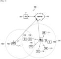
- the gNB 103 provides wireless broadband access to the network 130 for a second plurality of UEs within a coverage area 125 of the gNB 103.
- the second plurality of UEs includes the UE 115 and the UE 116.
- one or more of the gNBs 101-103 can communicate with each other and with the UEs 111-116 using 5G, LTE, LTE-A, WiMAX, or other advanced wireless communication techniques.
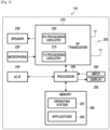
- the UE 116 includes one or more transceivers 210, a microphone 220, a speaker 230, a processor 240, an input/output (I/O) interface 245, an input 250, a display 255, and a memory 260.
- the memory 260 includes an operating system (OS) program 261 and one or more applications 262.
- OS operating system
- the controller/processor 378 is also coupled to the backhaul or network interface 382.
- the backhaul or network interface 382 allows the gNB 102 to communicate with other devices or systems over a backhaul connection or over a network.
- the backhaul or network interface 382 can support communications over any suitable wired or wireless connection(s).
- the gNB 102 is implemented as part of a cellular communication system (such as one supporting 5G or new radio access technology or NR, LTE, or LTE-A)
- the backhaul or network interface 382 can allow the gNB 102 to communicate with other gNBs over a wired or wireless backhaul connection.
- FIG. 3 illustrates one example of a gNB 102
- the gNB 102 can include any number of each component shown in FIG. 3 .
- an access point can include a number of backhaul or network interfaces 382, and the controller/processor 378 can support routing functions to route data between different network addresses.
- the gNB 102 can include multiple instances of each (such as one per RF transceiver).
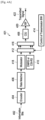
- One CSI-RS port is mapped onto a number of antenna elements that can be substantially larger than one and can be controlled by a bank of analog phase shifters 461.
- One CSI-RS port can then correspond to one sub-array that produces a narrow analog beam through analog beamforming 463.
- the analog beam can be configured to sweep across a wider range of angles 467 by varying the phase shifter bank across symbols or slots.
- a number of sub-arrays (equal to the number of RF chains) is same as a number of CSI-RS antenna ports NCSI-PORT.
- a digital beamforming unit 465 performs a linear combination across NCSI-PORT analog beams to increase precoding gain.
- analog beams are wideband (hence not frequency-selective)
- digital precoding can be varied across frequency sub-bands or resource blocks.
- a number of antenna elements can be larger for a given form factor
- a number of CSI-RS antenna ports that can correspond to the number of digitally precoded antenna ports, it typically limited due to hardware constraints, such as a feasibility to install a large number of ADCs/DACs at mmWave frequencies.
- cellular communication networks have been designed to establish wireless communication links between UEs and fixed communication infrastructure components, such as gNBs, that serve UEs in a wide or local geographic range.
- a wireless network can also be implemented by utilizing only device-to-device (D2D) communication links without the need for fixed infrastructure components.
- This type of network is typically referred to as an "ad-hoc" network.
- a hybrid communication network can support devices that connect both to fixed infrastructure components and to other D2D-enabled devices.
- UEs such as smartphones can be envisioned for D2D networks
- vehicular communication can also be supported by a communication protocol where vehicles exchange control or data information with other vehicles, or with infrastructure, or with other UEs.
- Such a network is referred to as a V2X network.
- Multiple types of communication links can be supported by nodes in a V2X network.
- the communication links can utilize same or different protocols and systems.
- subchannels can be defined as a group of resource blocks (RBs) over a time unit such as a slot or a subframe.
- RBs resource blocks
- a number of RBs per subchannel can vary or can be same.
- Subchannels are used to transmit data and control information.
- a second sub-channelization scheme corresponds to non-adjacent PSCCH and PSSCH transmissions in frequency.
- the RBs are divided into pools. One pool is used only for a PSCCH transmission with a SCI format and the PSCCH transmission can occupy two RBs.
- the second pool is used only for a PSSCH transmission with a TB and is divided into subchannels.
- An initial transmission of a TB in a PSSCH can be based on a sensing and resource selection procedure without prior resource reservation.
- a sidelink resource for an initial transmission of a TB in a PSSCH can be reserved, at least by an SCI format in a PSCCH that schedules a different TB, based on a sensing and resource selection procedure. This operation can be enabled/disabled by pre-configuration.
- all UEs in the set of UEs or a subset of UEs share a first PSFCH resource for HARQ-ACK information with ACK value and a second PSFCH resource for HARQ-ACK information with NACK value.
- Each PSFCH resource is mapped to a time, frequency, and code resource.
- Various embodiments of the present disclosure enable symbol-based resource sensing, slot-based resource sensing, resource reservation, and an adaptation of counter for sensing symbols and sensing slots.
- a UE For resource sensing, a UE, such as the UE 116, selects all or some of the candidate resources at one slot and then performs sensing on each selected candidate time-frequency resource. If the sensing succeeds and the time-frequency resource is available, the UE 116 can use that resource to transmit. If the sensing fails, the UE 116 can wait to resume resource sensing on available candidate resources in following slots or after a number of back-off slots.
- Nmin and Nmax there is a minimum and a maximum number of symbols, Nmin and Nmax, where each N is selected from [Nmin, Nmax] as configured in each access class with allowed values.
- the UE 116 can be configured according to Table 2, which is an example realization of Table 1.
- Access Class Nmin Nmax the number of backoff slots Number of maximum channel occupancy slots 0 0 0 0 1 1 1 3 0 3 2 4 9 1 8 3 10 14 3 10
- the UE 116 with access class 0 has the highest priority where sensing is not required to be performed. However, the UE 116 does not occupy more than one slot for transmissions. For UEs with other access classes, a number of symbols N, a number of back-off slots, and a number of maximum channel occupancy slots can increase according to an increase in a corresponding access class number.
- the UE 116 can be configured according to Table 4, which is an example realization of Table 3.
- Table 4 Access Classes Nmin Nmax Number of maximum channel occupancy slots 0 0 0 1 1 1 3 3 2 4 8 8 3 9 14 10
- Access Classes N the number of backoff slots Number of maximum channel occupancy slots 0 x x x 1 x x x ... ... ... ... ... ... ... ... n x x x
- the UE 116 senses the channel for a number of N slots to determine whether or not the channel can be used for transmissions.
- the UE 116 can be configured with one or more of the following: a number of slots N that the UE 116 senses for channel access, a minimum and a maximum number of slots N, Nmin and Nmax, and a number of slots that the UE 116 can occupy in the channel.
- Table 7 includes a minimum and a maximum number of slots N, Nmin and Nmax. Each N can be selected from [Nmin, Nmax] that is configured in each access class with allowed values. As an example, the UE 116 can be configured according to Table 8 which is an example realization of Table 7. [Table 8] Access Class Nmin Nmax Number of maximum channel occupancy slots 0 0 0 1 1 1 3 3 2 4 9 8 3 10 14 10
- the UE 116 with access class 0 has the highest priority where sensing is not required to be performed. However, the UE 116 cannot occupy more than one slot for transmissions. For UEs with other access classes, the number of slots N for sensing and the number of maximum channel occupancy slots can increase with the increase in the access class number.
- a resource reservation field indicates a periodicity of reserved resource for transmission of a next transport block.
- the UE 116 sets the resource reservation field according to Table 10, for a field of 4 bits, based on indicated value X, where X is equal to the resource reservation interval provided by higher layers divided by 100.
- Table 10 Resource reservation field in SCI format 1 Indicated value X Condition '0001','0010',...,'1010' Decimal equivalent of the field
- the higher layer decides to keep the resource for the transmission of the next transport block and the value X meets 1 ⁇ X ⁇ 10. '1011' 0.5
- the higher layer decides to keep the resource for the transmission of the next transport block and the value X is 0.5.
- a periodic multi-slot resource can be reserved by a single SCI format.
- the SCI format can include a resource reservation field that indicates a periodicity for the resource reservation and a field for a number of consecutive slots that indicates a multi-slot resource.
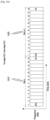
- FIG. 9 illustrates an SCI format field that includes time slots according to various embodiments of the present disclosure.
- the SCI format field in a slot l indicates four consecutive time slots that are reserved for the periodic resource. Slot 1 can correspond to slot n.
- the embodiment of the SCI format field in FIG. 9 is for illustration only. Other embodiments can be used without departing from the scope of the present disclosure.
- a one-time multi-slot resource can be reserved by a single SCI format for either initial transmission or for retransmission of a TB (HARQ-ACK based or blind retransmission).
- a field of a number of consecutive slots indicates a multi-slot resource for either initial transmission or retransmission.
- FIG. 10 illustrates an SCI format field including time slots according to various embodiments of the present disclosure.
- the SCI format field in a slot l indicates four consecutive time slots that are reserved for a retransmission resource starting from slot n, where slot 1 can correspond to slot n.
- the embodiment of the SCI format field shown in FIG. 10 is for illustration only. Other embodiments can be used without departing from the scope of the present disclosure.
- the SCI format can indicate both periodic resources and aperiodic resources.
- Aperiodic resources can be either consecutive or non-consecutive resources in time and be used for a one-time transmission.
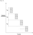
- a number of symbols N indicates a number of symbols the UE 116 uses to perform sensing.
- the value of N can be within a range of Nmin and Nmax.
- An initial value of N can be Nmin.
- the time gap between any two consecutive PSSCH transmissions with the TB is same.
- FIG. 13 illustrates time gaps between PSSCH transmissions of a same TB according to various embodiments of the present disclosure.
- the time gap is same between any two consecutive PSSCH transmissions of a same TB.
- the field SFgap indicates a time gap between any two consecutive PSSCH transmissions.
- the time domain gap can be in unit of slots or in a unit of a number of consecutive slots, or in milliseconds and can be configured by RRC signaling or be predetermined in the system operation.
- the embodiment of the time gaps between PSSCH transmissions shown in FIG. 13 is for illustration only. Other embodiments can be used without departing from the scope of the present disclosure.
- FIG. 14 illustrates time gaps between transmissions of a same TB according to various embodiments of the present disclosure.
- a time gap can be different between any two consecutive transmissions for a same TB.
- SFgap1 indicates the time gap between a first PSSCH transmission with a TB and a second PSSCH transmission with the TB
- SFgap2 indicates the time gap between the second PSSCH transmission with the TB and a third PSSCH transmission with the TB.
- the time domain gap can be in unit of slots or in a unit of a number of consecutive slots for a PSSCH transmission or in absolute time units such as milliseconds.
- the unit can be configured by RRC signaling or be predetermined in the system operation.
- the embodiment of the time gaps between transmissions shown in FIG. 14 is for illustration only. Other embodiments can be used without departing from the scope of the present disclosure.
- Various embodiments of the present disclosure provide mechanisms for indicating a frequency domain resource for a transmission or a retransmission of a TB in a PSSCH.
- a DCI format can provide resources for one or multiple sidelink transmissions of a PSSCH with a single TB.
- retransmission resources for a PSSCH with the TB are indicated by a DCI format.
- a frequency domain gap between two consecutive PSSCH transmissions with a same TB can be same or different.
- the frequency domain gap between a PSSCH with an initial transmission of a TB and a PSSCH with a first retransmission of the TB and the frequency domain gap between the PSSCH with the first retransmission of the TB and a PSSCH with a second retransmission of the TB can be same or different.
- An indication of the frequency domain gap can be beneficial when frequency resources available for transmissions of a TB are not evenly spaced.
- the DCI format can provide resources for one or for multiple sidelink PSSCH transmissions with single TB for configured grant type 2 PSSCH transmissions where the DCI format can also perform the activation of the PSSCH transmissions.
- configured grant type 1 where RRC configuration is used for resource configurations
- the frequency domain resources for transmissions of a single TB can be configured by RRC signaling.
- the frequency domain gap between any two consecutive transmissions for a same TB can be same. Then, there is only one frequency domain gap field in a DCI format activating configured grant type 2 PSSCH transmissions or in RRC signaling for configured grant type 1 or configured grant type 2, to indicate the frequency domain resources of the all PSSCH transmissions for a same TB.
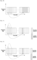
- FIG. 15 illustrates frequency gaps between PSSCH transmissions for a TB according to various embodiments of the present disclosure.
- the frequency domain gap is the same between any two consecutive PSSCH transmissions for a same TB.
- the field Fgap in the DCI format allocating resources for the PSSCH transmissions indicates the frequency domain gap between any two consecutive PSSCH transmissions.
- the frequency domain gap can be in a unit of subchannels that can be configured by RRC signaling or be predetermined in the system operation based on a total number of subchannels.
- the PSSCH transmissions for a single TB can be in same frequency domain resources and the frequency domain gap between any two consecutive transmissions is zero.
- a corresponding indication can be omitted in the DCI format or in the RRC signaling for configured grant PSSCH transmissions.
- the embodiment of the frequency gaps between transmissions shown in FIG. 15 is for illustration only. Other embodiments can be used without departing from the scope of the present disclosure.
- the frequency domain gap between any two consecutive transmissions for a same TB can be different.
- a frequency domain gap field value in a DCI format including a DCI format activating configured grant type 2 PSSCH transmissions, or in RRC signaling for configured grant type 1 or configured grant type 2 PSSCH transmissions can indicate a frequency domain gap between two consecutive PSSCH transmissions.
- FIG 16 illustrates frequency domain gaps between PSSCH transmissions for a TB according to various embodiments of the present disclosure.
- the frequency domain gap is different between consecutive transmissions for a same TB.
- Fgap1 indicates a first frequency domain gap between an initial PSSCH transmission with a TB and a second PSSCH transmission with the TB.
- Fgap2 indicates a frequency domain gap between the second PSSCH transmission with the TB and a third PSSCH transmission with the TB, and so on.
- the frequency domain gap can be in a unit of number of subchannels wherein the unit can be configured or be predetermined in the system operation based on a total number of subchannels.
- the embodiment of the frequency gaps between transmissions shown in FIG. 16 is for illustration only. Other embodiments can be used without departing from the scope of the present disclosure.
- Various embodiments of the present disclosure provide mechanisms for a CSI report for multiple destination UEs.
- the CSI report by the transmitter UE 116 to the gNB 102 can include CSI for transmissions from UE 116 to the multiple destination UEs.
- a separate CSI report is provided by the transmitter UE 116 to the gNB 102 for each destination UE.
- each CSI report is provided at the physical layer, a corresponding number of required resources can be large when an explicit destination UE index is included in each CSI report.
- a CSI report can be provided by higher layers such as by a MAC CE or by RRC signaling. The same can apply for a CSI report provided by a destination UE to transmitter UE 116.
- the gNB 102 can allocate the resource to the transmitter UE 116 that transmits to the corresponding destination UE using the allocated resource.
- a single CSI report can be provided by the transmitter UE 116 to the gNB 102 for all destination UEs.
- the single CSI report can be the report with the average CSI, or the best CSI, or the worst CSI among the CSI reports for all destination UEs.
- the gNB 102 can use the single CSI report to allocate the resource for the transmitter UE 116.
- a single CSI report can be applicable for groupcast transmission.
- Various embodiments of the present disclosure provide BSR reporting and corresponding DCI format indication for multiple destination UEs. For example, when a transmitter UE 116 has data to transmit to different destination UEs, the transmitter UE 116 can provide to the gNB 102 a BSR report separately for each destination UE. When the gNB 102 schedules/indicates the resource for the transmitter UE 116 for PSSCH transmission to a destination UE, the gNB 102 can indicate, for example in the corresponding DCI format, the destination UE that the transmitter UE 116 transmits a PSSCH to using the indicated resource.
- Each BSR can include an index for a corresponding destination UE.
- the index in each BSR is not necessarily same as the destination UE index and an association can be determined by the transmitter UE.
- index 0 for a BSR can indicate destination UE a
- index 1 for a BSR report can indicate destination UE b.
- the gNB 102 can schedule a resource corresponding to a BSR report and indicate, in the DCI format, the resource and the corresponding index.
- the transmitter UE 116 can determine the destination UE for transmitting a PSSCH to using the indicated resource.
- FIG. 17 illustrates a gNB and a transmitter UE according to various embodiments of the present disclosure.
- the embodiment of the gNB and a transmitter UE shown in FIG. 17 is for illustration only. Other embodiments can be used without departing from the scope of the present disclosure.
- an index can be assigned to the destination UE.
- the transmitter UE 116 sends a BSR with an index n corresponding to the destination UE.
- the gNB 102 schedules/indicates a resource to the transmitter UE 116 and indicates in the DCI format the index n.
- the transmitter UE 116 transmits a PSSCH to the destination UE using the indicated resource.
- a retransmission resource can be allocated by the gNB 102 to the transmitter UE 116 for a PSSCH transmission when the gNB 102 receives a NACK from the UE 116 for a TB in a previous PSSCH transmission.
- the multiple HARQ-ACK information bits can be multiplexed in a same PUCCH resource.
- Each HARQ-ACK in the same HARQ-ACK codebook can be allocated an index by the transmitter UE 116.
- the gNB 102 can schedule a resource corresponding to a HARQ-ACK index and indicate, in the DCI format, the resource for a PSSCH transmission and the corresponding index.
- the transmitter UE 116 can know the destination UE and transmit a PSSCH to the destination UE using the resource indicated by the DCI format.
- FIG. 18 illustrates a transmitter UE and a gNB according to various embodiments of the present disclosure.
- the transmitter UE can be the UE 116 and the gNB can be the gNB 102.
- the embodiment of the gNB and a transmitter UE shown in FIG. 18 is for illustration only. Other embodiments can be used without departing from the scope of the present disclosure.
- the transmitter UE 116 when the transmitter UE 116 has HARQ ACK information to report to the gNB 102 for requesting a resource to retransmit a TB or to transmit a new TB to destination UEs, such as the UEs 111-115, an index can be implicitly assigned to each HARQ-ACK information bit that is related with the corresponding destination UE 111-115. Then, the gNB 102 schedules/indicates a resource for the transmitter UE 116 and indicates, in the DCI format, the index n. When the transmitter UE 116 receives the DCI format, the transmitter UE 116 transmits the PSSCH to a destination UE, from the destination UE 111-115, as determined by the index n using the resource.
- different DCI formats can be used for NR Uu over NR sidelink and NR Uu over LTE.
- Different RNTIs for NR sidelink and LTE sidelink are used to scramble the CRC bits of the DCI formats to distinguish between NR and LTE sidelink.
- the disclosure considers that the DCI formats for both NR Uu over NR sidelink and NR Uu over LTE have a same payload size. If a number of information bits in one of the two DCI formats is less than in the other of the two DCI formats, zeros are appended to the DCI format with a fewer number of information bits until both DCI formats have same size.
- a multi-beam CSI-RS is configured and transmitted by a transmitter UE, such as UE 116, to a receiver UE.
- the receiver UE performs beam measurement and reports the beam measurement result to the transmitter UE.
- the receiver UE reports N selected CSI-RS resource indicators (CRIs) and corresponding L1-RSRP from a set of CSI-RS resources.
- the present disclosure further provides mechanisms for beam indication of PSFCH transmission.
- the UE that transmits PSCCH/PSSCH also includes in a SCI format scheduling the PSSCH transmission an indication for a beam to be used by the UE that transmits the associated PSFCH in response to the PSCCH/PSSCH reception.
- the present disclosure further provides mechanisms for resource allocation.
- the resource allocation for a PSCCH/PSSCH transmission using multiple beams can be performed separately for each beam. Resource exclusion can be performed separately for different beam used for receptions and RSRP/RSSI is calculated based upon each corresponding receiver beam in sensing and resource selection procedures.
- the resource for a PSFCH transmission using a beam from the multiple beams can be associated with/determined from the beam used for a corresponding PSCCH/PSSCH reception.
- a transmission of a reservation signal can be over several symbols of a slot where the reservation signal can be transmitted using a different beam per symbol or per number of symbols.
- the number of symbols can be configured or can be predetermined in the system operation.
- AGC automatic gain control
- GP guard period
- the reservation signal can indicate a transmission beam that is used by the transmitter UE 116 to transmit an associated PSCCH/PSSCH.
- a beam for the reservation signal transmission provides a same transmission beam indication for the associated PSCCH/ PSSCH.
- each beam for the reservation signal transmission provides a same transmission beam indication for the associated PSCCH/PSSCH transmission.
- FIG. 21 illustrates a reservation signal indicating one beam for a PSCCH/PSSCH transmission according to various embodiments of the present disclosure.
- FIG. 21 illustrates a reservation signal that is transmitted using three beams 2110, 2120, and 2130.
- the reservation signal transmission using beams 2110, 2120, 2130 indicates one transmission beam 2140 for an associated PSCCH/PSSCH transmission, for example for groupcast or broadcast transmissions.
- the embodiment of the reservation signal shown in FIG. 21 is for illustration only. Other embodiments can be used without departing from the scope of the present disclosure.
- FIG. 22 illustrates a transmission of a reservation signal that indicates multiple beams for associated PSCCH/PSSCH transmissions according to various embodiments of the present disclosure.
- the embodiment of the reservation signal shown in FIG. 22 is for illustration only. Other embodiments can be used without departing from the scope of the present disclosure.
- a reservation signal is transmitted using three beams 2210, 2220, and 2230.
- the reservation signal indicates multiple transmission beams 2240, 2250, and 2260 for associated PSCCH/PSSCH transmissions.
- the first beam 2210 indicates the transmission beam 2240
- the second beam 2220 indicates the transmission beam 2250
- the third beam 2230 indicates the transmission beam 2260, for example, for unicast transmissions.
- the transmission beam indicated by the reservation signal can be in the form of transmission configuration indicator (TCI) state (TCI-state) that contains parameters for configuring a quasi co-location relationship between the sidelink reference signals and the DM-RS ports of the corresponding PSCCH/PSSCH transmission.
- the quasi co-location relationship can be configured by the higher layer parameter qcl-Type for the sidelink reference signal.
- the sidelink reference signals can be provided either by an SSB-index for a SS/PBCH block or by a CSI-RS resource ID for a CSI-RS.
- the TCI state field in a received reservation signal indicates the TCI state for the PSCCH/PSSCH reception.
- a UE uses the TCI-State according to the value of the TCI state field in the detected reservation signal to determine a PSCCH/PSSCH antenna port quasi co-location if a time between the reception of the reservation signal and the corresponding PSCCH/PSSCH reception is equal to or greater than a threshold provided by higher layer parameter Threshold-Sched-Offset.
- FIG. 23 illustrates a beam for a PSCCH/PSSCH reception that is associated with a reservation signal according to various embodiments of the present disclosure.
- the reservation signal is received using three beams 2310, 2320, and 2330.
- Beams 2340, 2350, and 2360 of the PSCCH/PSSCH reception are associated with the three beams 2310, 2320, and 2330, respectively, of the reservation signal when a time between the reception of the reservation signal and the corresponding PSCCH/PSSCH reception is less than a threshold provided by higher layer parameter Threshold-Sched-Offset.
- the embodiment of the reception beam shown in FIG. 23 is for illustration only. Other embodiments can be used without departing from the scope of the present disclosure.
- the first stage SCI format can be used for sensing and reservation of sidelink resources for subsequent PSCCH/PSSCH transmission(s).
- the first stage SCI format can be used by the other UEs to determine whether or not to exclude from transmission resources that are reserved by the UE that transmits the PSCCH with the first stage SCI format.
- the first stage SCI format is for sensing purpose and can be broadcasted to all other UEs or to UE with the range of the transmitter UE.
- the PSCCH that includes the first stage SCI format can be transmitted using multiple beams.
- the PSCCH that provides the first stage SCI format can be transmitted/received over multiple slots using different beams in different slots. For each transmission/reception beam of the PSCCH, there can be an AGC at the beginning of the slot and a GP at the end of the slot. Similar, a PSSCH transmission/ reception that is scheduled by the first stage SCI format can be over multiple slots with an AGC at the beginning of the slot and a GP at the end of the slot when PSCCH and PSSCH are multiplexed in the same slot and use same transmission and reception beams to transmit and receive, respectively.
- FIG. 24 illustrates a PSCCH transmission that provides a first stage SCI format using a different beam per slot over respective multiple slots according to various embodiments of the present disclosure.
- the PSCCH transmission uses beam 2410 in slot n and beam 2420 in slot n + 1.
- the embodiment of the PSCCH transmission that provides the first stage SCI format using a different beam per slot over respective multiple slots shown in FIG. 24 is for illustration only. Other embodiments can be used without departing from the scope of the present disclosure.
- Various embodiments of the present disclosure provide mechanisms for a beam indication for a PSCCH reception that includes a second stage SCI format or for a PSSCH reception.
- the PSCCH reception that provides the first stage SCI signal can be of broadcast type signal and can be used by other UEs for sensing.
- the first stage SCI format can indicate a beam that is used by the transmitter UE to transmit the PSCCH that provides the second SCI format and to transmit a PSSCH in resources indicated by the first stage SCI format.
- the transmission/reception beam for each PSCCH that provides the first stage SCI format is same as the transmission/reception beam for the PSCCH that provides the second stage SCI format and of the associated PSSCH.
- the first stage SCI format can indicate a beam (TCI state) for the transmission/reception of the PSCCH with the second stage SCI format and of the associated PSSCH.
- FIG. 25 illustrates a first stage SCI format indicating a beam for transmission/ reception of a PSCCH with the second SCI format and of an associated PSSCH according to various embodiments of the present disclosure.
- the PSCCH that provides the first stage SCI format is transmitted using three beams 2510, 2520, and 2530.
- the first stage SCI format indicates one beam 2540 of the PSCCH transmission that provides the second stage SCI format and of the associated PSSCH transmission.
- the embodiment of the first stage SCI format shown in FIG. 25 is for illustration only. Other embodiments can be used without departing from the scope of the present disclosure.
- FIG. 26 illustrates a first stage SCI format indicating multiple beams for a transmission of a PSCCH with a second stage SCI format and of an associated PSSCH according to various embodiments of the present disclosure.
- a PSCCH that provides the first stage SCI format can be transmitted using multiple beams including three beams 2610, 2620, and 2630.
- the first beam 2610 indicates the first beam for transmission of a PSCCH with the second stage SCI format and of an associated PSSCH 2640
- the second beam 2620 indicates the second beam for transmission of a PSCCH with the second stage SCI format and of an associated PSSCH2650
- the third beam 2630 indicates the third beam for transmission of a PSCCH with the second stage SCI format and of an associated PSSCH 2660.
- the association among the beams can be indicated by the first stage SCI format, or configured by RRC signaling, or be predetermined in the system operation.
- the embodiment of the first stage SCI format shown in FIG. 26 is for illustration only. Other embodiments can be used without departing from the scope of the present disclosure.
- the transmission beam that the first SCI format indicates can be in the form of TCI-state that contains parameters for configuring a quasi co-location relationship between the sidelink reference signals and the DM-RS ports of the PSCCH with the second stage SCI format and of the associated/scheduled PSSCH.
- the quasi co-location relationship can be configured by higher layer parameter qcl-Type for the sidelink reference signal.
- the sidelink reference signals can be determined either by a SSB-index for a SS/PBCH block or by a CSI-RS resource ID for a CSI-RS.
- the TCI state field in the first state SCI format indicates the TCI state for the transmission of the PSCCH with the second stage SCI format and of the scheduled PSSCH.
- a UE uses the TCI-State value indicated by the value of the TCI state field in the detected first stage SCI format for determining an antenna port quasi co-location for the reception of the PSCCH with the second stage SCI format or of the PSSCH, if a time between the reception of the PSCCH with the first stage SCI format and the reception of the PSCCH with the second stage SCI format or of the PSSCH is equal to or greater than a threshold provided by higher layer parameter Threshold-Sched-Offset.
- the UE can assume that the DM-RS ports of the PSCCH with the second stage SCI format or of the PSSCH are quasi co-located with the RS(s) in the TCI state with respect to the QCL parameter(s) used for the first stage SCI quasi co-location indication.
- FIG. 27 illustrates a determination for a beam for a reception of a PSCCH with a second stage SCI format or of a scheduled PSSCH based on a beam for a reception of a PSCCH with a first SCI format according to various embodiments of the present disclosure.
- the embodiment of the transmission beam shown in FIG. 27 is for illustration only. Other embodiments can be used without departing from the scope of the present disclosure.
- a UE receives a PSCCH that provides a first stage SCI format using different beams including three beams 2710, 2720, and 2730.
- the first beam 2710 is associated with a reception of a PSCCH that provides the second SCI format or of a scheduled PSSCH 2740.
- the second beam 2720 is associated with a reception of a PSCCH that provides the second SCI format or of a scheduled PSSCH 2750.
- the third beam 2730 is associated with a reception of a PSCCH that provides the second stage SCI format or of a scheduled PSSCH 2760.
- the three beams 2710, 2720, and 2730 are associated with the three beams for the reception of a PSCCH that provides the second stage SCI format or of the scheduled PSSCH 2740, 2750, 2760, respectively, when a time between the reception of the PSCCH that provides the first stage SCI format and the reception of the PSCCH that provides the second stage SCI format or of the scheduled PSSCH is less than a threshold provided by higher layer parameter Threshold-Sched-Offset.
- a CSI-RS is configured and transmitted using multiple beams by the transmitter UE to the receiver UE.
- the receiver UE performs beam measurement, using the received CSI-RS, and reports the beam measurement result to the transmitter UE.
- the beam measurement result can be a CSI-RS resource index resulting to a larger SINR if CSI-RS is transmitted for beam measurement and reporting.
- the receiver UE can select N CRIs and corresponding L1-RSRP values to report from a set of CSI-RS resources, for example according to a descending SINR value starting from the largest.
- the transmitter UE performs resource allocation within the resource for CSI-RS transmission using multiple beams. Similar, the receiver UE performs resource allocation for a CSI report that includes CSI reports for one or more for CSI-RS receptions using the multiple beams.
- the resource allocation procedure for CSI-RS transmission using multiple beams or for a CSI report in response to CSI-RS reception over the multiple beams can be same as for a procedure for a resource allocation for a PSCCH/PSSCH transmission/reception using multiple beams.
- Various embodiments of the present disclosure provide mechanisms for beam indication for a PSFCH transmission.
- the beam of the PSFCH transmission can be indicated in several ways.
- a UE can transmit a PSFCH using multiple beams. For example, the UE can transmit the PSFCH using multiple beams for groupcast or when the UE does not acquire a beam used for a corresponding PSCCH/PSSCH reception by beam training for unicast.
- a UE transmits a PSFCH using a beam that the UE derives from a corresponding reception beam of a PSCCH/PSSCH reception associated with the PSFCH transmission. This is typically referred to as beam correspondence.
- a UE that transmits a PSCCH/PSSCH indicates a beam in the SCI format provided by the PSCCH for the UE that receives the PSCCH/PSSCH to use for transmission of an associated PSFCH.
- the UE that transmits the PSCCH/PSSCH can derive a beam for the associated PSFCH transmission by beam training based on beam measurements of the reference signals transmitted by the UE that transmits the PSFCH.
- FIG. 28 illustrates an indication of a PSFCH transmission beam by SCI format according to various embodiments of the present disclosure.
- the embodiment of the PSFCH beam indication shown in FIG. 28 is for illustration only. Other embodiments can be used without departing from the scope of the present disclosure.
- the UE that transmits the PSCCH/PSSCH indicates in a reservation signal a beam for the UE that receives the PSCCH/PSSCH to use for the associated PSFCH transmission.
- the UE that transmits PSCCH/PSSCH can derive the beam of the associated PSFCH transmission by beam training based on beam measurements from received reference signals that are transmitted by the UE that transmits the PSFCH.
- the beam indication can be a CSI-RS resource index.
- higher layers can configure a list of reference signal IDs, such as CSI-RS resource IDs, to be associated with a PSFCH resource and a MAC-CE or a SCI format scheduling a PSSCH reception can indicate one of the reference signal IDs for the UE transmitting the PSFCH to determine a beam for the PSFCH transmission.
- higher layers can configure a set of TCI states and the SCI format or a MAC CE can indicate a TCI state from the set of TCI states for the PSFCH transmission.
- sidelink resources can be reserved and used by a UE for PSCCH/PSSCH transmission.
- the UE allocates resources for PSCCH/PSSCH transmission using one beam.
- the PSCCH/PSSCH transmission is a broadcast/groupcast, the UE allocates resources for PSCCH/PSSCH transmission using multiple beams.
- the transmitter UE can allocate resources for PSCCH/PSSCH transmission using multiple beams.
- a UE when a UE performs a sidelink measurement for excluding resources, the UE applies a beam for a reception of a sidelink signal used to measure a sidelink RSRP.
- the UE applies the beam for the reception of the sidelink signal to measure a sidelink RSSI. For example, as shown in FIG. 27 , RSRP/ RSSI can be calculated based on each corresponding beam for the sidelink signal reception.
- the DCI format may provide information for scheduling at least one of the PSSCH transmissions and includes a first HARQ process number field having a first value.
- the UE may then transmit, for example to the other UE(s), a PSCCH that provides a SCI format that provides information for scheduling the at least one PSSCH transmission and includes a second HARQ process number field with a second value that is determined by the UE based on a first value of the first HARQ process number field.
- the UE may also receive, for example via a PDCCH, a configuration for a maximum number of PSSCH transmissions that provide a same TB.
- the UE transmits the generated HARQ-ACK codeword in a PUCCH, for example to the BS (operation 3125).
Landscapes
- Engineering & Computer Science (AREA)
- Signal Processing (AREA)
- Computer Networks & Wireless Communication (AREA)
- Quality & Reliability (AREA)
- Mobile Radio Communication Systems (AREA)
Claims (4)
- Verfahren für New Radio(NR)-Uu, das eine Long Term Evolution(LTE)-Sidelink-Übertragung steuert, wobei das Verfahren durch ein Benutzergerät, UE, Folgendes umfasst:Übertragen eines Wertes von X, den das UE unterstützt, an eine Basisstation;Empfangen eines Downlink-Steuerungsinformations(DCI)-Formats von der Basisstation, wobei das DCI-Format eine Übertragung eines LTE-PSSCH (gemeinsam genutzter physikalischer Sidelink-Kanal) aktiviert; undÜbertragen des LTE-PSSCH in einem ersten LTE-Teilrahmen nach Z+X Millisekunden, ms, von einem Teilrahmen eines physikalischen Downlink-Steuerungskanals(PDCCH)-Empfangs, der das DCI-Format bereitstellt,wobei Z ein Zeitversatz ist, der in LTE-Vehicle-to-everything(V2X)-Spezifikationen definiert ist, und X>0 ist und der Wert von X vorbestimmt ist, und X eine Planungslatenz anzeigt, die sich aus einer Koordinationslatenz zwischen einem NR-Modul des UE und einem LTE-Modul des UE ergibt.
- Benutzergerät, UE, für New Radio(NR)-Uu, das eine Long Term Evolution(LTE)-Sidelink-Übertragung steuert, wobei das UE Folgendes umfasst:einen Transceiver; undeine Steuerung, die mit dem Transceiver gekoppelt und konfiguriert ist, um Folgendes zu steuern:Übertragen eines Wertes von X, den das UE für die Zuweisung von LTE-Sidelink-Ressourcen unterstützt, an eine Basisstation,Empfangen eines Downlink-Steuerungsinformations(DCI)-Formats von der Basisstation, wobei das DCI-Format eine Übertragung eines LTE-PSSCH (gemeinsam genutzter physikalischer Sidelink-Kanal) aktiviert, undÜbertragen des LTE-PSSCH in einem ersten LTE-Teilrahmen nach Z+X Millisekunden, ms, von einem Teilrahmen eines physikalischen Downlink-Steuerungskanals(PDCCH)-Empfangs, der das DCI-Format bereitstellt,wobei Z ein Zeitversatz ist, der in LTE-Vehicle-to-everything(V2X)-Spezifikationen definiert ist, und X>0 ist und der Wert von X vorbestimmt ist, und X eine Planungslatenz anzeigt, die sich aus einer Koordinationslatenz zwischen einem NR-Modul des UE und einem LTE-Modul des UE ergibt.
- Verfahren für New Radio(NR)-Uu, das eine Sidelink-Übertragung steuert, durch eine Basisstation, wobei das Verfahren Folgendes umfasst:Empfangen eines Wertes von X, den das UE unterstützt, von einem Benutzergerät, UE; undÜbertragen eines Downlink-Steuerungsinformations(DCI)-Formats an das UE, wobei das DCI-Format eine Übertragung eines LTE-PSSCH (gemeinsam genutzter physikalischer Sidelink-Kanal) aktiviert,wobei der LTE-PSSCH in einem ersten LTE-Teilrahmen nach Z+X Millisekunden, ms, von einem Teilrahmen eines physikalischen Downlink-Steuerungskanals(PDCCH)-Empfangs übertragen wird, der das DCI-Format bereitstellt, wobei LTE-Sidelink-Ressourcen basierend auf dem Wert von X zugewiesen werden, undwobei Z ein Zeitversatz ist, der in LTE-Vehicle-to-everything(V2X)-Spezifikationen definiert ist, und X>0 ist und der Wert von X vorbestimmt ist, und X eine Planungslatenz anzeigt, die sich aus einer Koordinationslatenz zwischen einem NR-Modul des UE und einem LTE-Modul des UE ergibt.
- Basisstation für New Radio(NR)-Uu, das eine Long Term Evolution(LTE)-Sidelink-Übertragung steuert, wobei die Basisstation Folgendes umfasst:einen Transceiver; undeine Steuerung, die mit dem Transceiver gekoppelt und konfiguriert ist, um Folgendes zu steuern:Empfangen eines Wertes von X, den das UE unterstützt, von einem Benutzergerät, UE, undÜbertragen eines Downlink-Steuerungsinformations(DCI)-Formats an das UE, wobei das DCI-Format eine Übertragung eines LTE-PSSCH (gemeinsam genutzter physikalischer Sidelink-Kanal) aktiviert,wobei der LTE-PSSCH in einem ersten LTE-Teilrahmen nach Z+X Millisekunden, ms, von einem Teilrahmen eines physikalischen Downlink-Steuerungskanals(PDCCH)-Empfangs übertragen wird, der das DCI-Format bereitstellt, wobei LTE-Sidelink-Ressourcen basierend auf dem Wert von X zugewiesen werden, undwobei Z ein Zeitversatz ist, der in LTE-Vehicle-to-everything(V2X)-Spezifikationen definiert ist, und X>0 ist und der Wert von X vorbestimmt ist, und X eine Planungslatenz anzeigt, die sich aus einer Koordinationslatenz zwischen einem NR-Modul des UE und einem LTE-Modul des UE ergibt.
Applications Claiming Priority (4)
| Application Number | Priority Date | Filing Date | Title |
|---|---|---|---|
| US201962835644P | 2019-04-18 | 2019-04-18 | |
| US201962884477P | 2019-08-08 | 2019-08-08 | |
| US16/847,416 US11233607B2 (en) | 2019-04-18 | 2020-04-13 | Method and apparatus for configuration of resource sensing in NR V2X resource allocation |
| PCT/KR2020/005161 WO2020213986A1 (en) | 2019-04-18 | 2020-04-17 | Method and apparatus for configuration of resource sensing in nr v2x resource allocation |
Publications (3)
| Publication Number | Publication Date |
|---|---|
| EP3857770A1 EP3857770A1 (de) | 2021-08-04 |
| EP3857770A4 EP3857770A4 (de) | 2021-12-01 |
| EP3857770B1 true EP3857770B1 (de) | 2025-07-02 |
Family
ID=72838181
Family Applications (1)
| Application Number | Title | Priority Date | Filing Date |
|---|---|---|---|
| EP20790826.0A Active EP3857770B1 (de) | 2019-04-18 | 2020-04-17 | Verfahren und vorrichtung zur konfiguration von ressourcenerfassung in einer nr-v2x-ressourcenzuweisung |
Country Status (4)
| Country | Link |
|---|---|
| EP (1) | EP3857770B1 (de) |
| KR (1) | KR102765422B1 (de) |
| CN (1) | CN113169830B (de) |
| WO (1) | WO2020213986A1 (de) |
Families Citing this family (22)
| Publication number | Priority date | Publication date | Assignee | Title |
|---|---|---|---|---|
| CN113287357B (zh) * | 2019-01-11 | 2023-08-01 | Lg电子株式会社 | 在无线通信系统中发送反馈信息的方法 |
| WO2021066436A1 (ko) * | 2019-10-02 | 2021-04-08 | 엘지전자 주식회사 | Nr v2x에서 타이밍 오프셋을 기반으로 lte 사이드링크 전송을 수행하는 방법 및 장치 |
| US11677512B2 (en) * | 2020-02-12 | 2023-06-13 | Apple Inc. | Sidelink HARQ |
| US20220200737A1 (en) * | 2020-12-17 | 2022-06-23 | Qualcomm Incorporated | Hybrid automatic repeat request feedback resource configuration for sidelink with carrier aggregation |
| US20240039601A1 (en) * | 2021-02-04 | 2024-02-01 | Qualcomm Incorporated | Iterative precoder computation and coordination for improved sidelink and uplink coverages |
| EP4316074A1 (de) * | 2021-03-30 | 2024-02-07 | InterDigital Patent Holdings, Inc. | Auf teilweiser erfassung basierende ressourcenzuweisung |
| US11647500B2 (en) * | 2021-08-02 | 2023-05-09 | Qualcomm Incorporated | Transmitting beam schedules to and receiving beam schedules from sidelink user equipments |
| WO2023010399A1 (zh) * | 2021-08-05 | 2023-02-09 | 富士通株式会社 | 设备间协作装置以及方法 |
| CN115733578A (zh) * | 2021-08-30 | 2023-03-03 | 上海移远通信技术股份有限公司 | 一种被用于无线通信的节点中的方法和装置 |
| WO2023029008A1 (zh) * | 2021-09-03 | 2023-03-09 | Oppo广东移动通信有限公司 | 信息传输方法、设备及存储介质 |
| CN115835381B (zh) * | 2021-09-17 | 2026-01-09 | 展讯通信(上海)有限公司 | 通信方法及装置、计算机可读存储介质及计算机程序产品 |
| US12256384B2 (en) * | 2021-10-18 | 2025-03-18 | Qualcomm Incorporated | Configuring sidelink transmission configuration indicator states |
| US20230117782A1 (en) * | 2021-10-19 | 2023-04-20 | Samsung Electronics Co., Ltd. | Device for transmitting data using sidelink in wireless communication system and operation method thereof |
| CN114071760B (zh) * | 2021-12-27 | 2024-09-27 | 成都爱瑞无线科技有限公司 | 数据通信方法、装置、电子设备及存储介质 |
| CN118556377A (zh) * | 2022-01-24 | 2024-08-27 | Oppo广东移动通信有限公司 | 侧行反馈信道的传输方法、装置、终端及存储介质 |
| EP4496370A4 (de) * | 2022-03-14 | 2025-12-10 | Ntt Docomo Inc | Endgerät und kommunikationsverfahren |
| CN116939820A (zh) * | 2022-03-31 | 2023-10-24 | 展讯通信(上海)有限公司 | 一种psfch传输方法、装置、芯片及模组设备 |
| EP4500769A1 (de) * | 2022-04-26 | 2025-02-05 | InterDigital Patent Holdings, Inc. | Verfahren und vorrichtung zur koexistenz von nr- und lte-v2x-systemen in kokanälen |
| WO2024073028A1 (en) * | 2022-09-29 | 2024-04-04 | Ofinno, Llc | Sidelink beam management for sidelink feedback channel |
| EP4366425A1 (de) * | 2022-11-02 | 2024-05-08 | Comcast Cable Communications LLC | Zuweisung von aufeinanderfolgenden ressourcen zur signalübertragung |
| CN119732147A (zh) * | 2022-11-04 | 2025-03-28 | Oppo广东移动通信有限公司 | 用于保护侧行链路通信中资源的用户设备和方法 |
| EP4668598A1 (de) * | 2023-02-14 | 2025-12-24 | LG Electronics Inc. | Verfahren und vorrichtung zur auswahl eines strahls zum empfang mehrerer rückkopplungsteile |
Family Cites Families (5)
| Publication number | Priority date | Publication date | Assignee | Title |
|---|---|---|---|---|
| JP2018029323A (ja) * | 2016-08-10 | 2018-02-22 | ソニー株式会社 | 通信装置及び通信方法 |
| WO2018174661A1 (en) * | 2017-03-24 | 2018-09-27 | Samsung Electronics Co., Ltd. | Resource selection method in vehicle to everything communication and apparatus therefore |
| CN108632781B (zh) * | 2017-03-24 | 2023-10-31 | 北京三星通信技术研究有限公司 | 车对外界通信中的资源选择或重选方法及用户设备 |
| WO2018203669A1 (ko) * | 2017-05-01 | 2018-11-08 | 엘지전자 주식회사 | 무선 통신 시스템에서 단말의 d2d 동작 방법 및 상기 방법을 이용하는 단말 |
| EP3619882B1 (de) * | 2017-05-04 | 2022-11-23 | Apple Inc. | Datenstrukturen und übetragungsschemata für die aufwärtsstrecke der übertragung in nr-kommunikationssystemen |
-
2020
- 2020-04-17 CN CN202080006678.4A patent/CN113169830B/zh active Active
- 2020-04-17 WO PCT/KR2020/005161 patent/WO2020213986A1/en not_active Ceased
- 2020-04-17 KR KR1020217028366A patent/KR102765422B1/ko active Active
- 2020-04-17 EP EP20790826.0A patent/EP3857770B1/de active Active
Also Published As
| Publication number | Publication date |
|---|---|
| KR20210143746A (ko) | 2021-11-29 |
| KR102765422B1 (ko) | 2025-02-12 |
| CN113169830B (zh) | 2022-06-24 |
| CN113169830A (zh) | 2021-07-23 |
| EP3857770A4 (de) | 2021-12-01 |
| EP3857770A1 (de) | 2021-08-04 |
| WO2020213986A1 (en) | 2020-10-22 |
Similar Documents
| Publication | Publication Date | Title |
|---|---|---|
| US12375215B2 (en) | Method and apparatus for configuration of resource sensing in NR V2X resource allocation | |
| EP3857770B1 (de) | Verfahren und vorrichtung zur konfiguration von ressourcenerfassung in einer nr-v2x-ressourcenzuweisung | |
| EP3959837B1 (de) | Verfahren und vorrichtung für v2x-sidelink-harq-verfahren in einem drahtloskommunikationssystem | |
| US12057933B2 (en) | Scheduling in communication systems with multiple service types | |
| US12089247B2 (en) | Method and apparatus for NR V2X resource selection | |
| US20240323942A1 (en) | Beam recovery in next generation wireless systems | |
| CN112740612B (zh) | 用于车辆对万物v2x通信中高可靠性传输的方法和装置 | |
| US11025374B2 (en) | Methods and apparatus for resource allocation and feedback in vehicle to vehicle communication | |
| US10764896B2 (en) | Method and apparatus for beam management in the unlicensed spectrum | |
| US20230224967A1 (en) | Method and apparatus for channel occupancy indication on sidelink | |
| US20240022376A1 (en) | Method and apparatus for sl multi-beam operation | |
| US20250089029A1 (en) | Method and apparatus for low power sensing for sidelink in wireless communication systems | |
| US20240334522A1 (en) | Beam failure recovery in sidelink | |
| US20250055535A1 (en) | Sl csi-rs signaling | |
| US20240236706A1 (en) | Sidelink initial beam acquisition | |
| US20230180278A1 (en) | Techniques for modifying channel state information |
Legal Events
| Date | Code | Title | Description |
|---|---|---|---|
| STAA | Information on the status of an ep patent application or granted ep patent |
Free format text: STATUS: THE INTERNATIONAL PUBLICATION HAS BEEN MADE |
|
| PUAI | Public reference made under article 153(3) epc to a published international application that has entered the european phase |
Free format text: ORIGINAL CODE: 0009012 |
|
| STAA | Information on the status of an ep patent application or granted ep patent |
Free format text: STATUS: REQUEST FOR EXAMINATION WAS MADE |
|
| 17P | Request for examination filed |
Effective date: 20210428 |
|
| AK | Designated contracting states |
Kind code of ref document: A1 Designated state(s): AL AT BE BG CH CY CZ DE DK EE ES FI FR GB GR HR HU IE IS IT LI LT LU LV MC MK MT NL NO PL PT RO RS SE SI SK SM TR |
|
| A4 | Supplementary search report drawn up and despatched |
Effective date: 20211028 |
|
| RIC1 | Information provided on ipc code assigned before grant |
Ipc: H04W 88/06 20090101ALN20211022BHEP Ipc: H04W 28/26 20090101ALI20211022BHEP Ipc: H04W 72/12 20090101ALI20211022BHEP Ipc: H04W 72/04 20090101ALI20211022BHEP Ipc: H04W 4/40 20180101ALI20211022BHEP Ipc: H04L 5/00 20060101ALI20211022BHEP Ipc: H04L 1/16 20060101ALI20211022BHEP Ipc: H04L 1/18 20060101AFI20211022BHEP |
|
| STAA | Information on the status of an ep patent application or granted ep patent |
Free format text: STATUS: EXAMINATION IS IN PROGRESS |
|
| DAV | Request for validation of the european patent (deleted) | ||
| DAX | Request for extension of the european patent (deleted) | ||
| 17Q | First examination report despatched |
Effective date: 20220711 |
|
| GRAP | Despatch of communication of intention to grant a patent |
Free format text: ORIGINAL CODE: EPIDOSNIGR1 |
|
| STAA | Information on the status of an ep patent application or granted ep patent |
Free format text: STATUS: GRANT OF PATENT IS INTENDED |
|
| INTG | Intention to grant announced |
Effective date: 20250311 |
|
| GRAS | Grant fee paid |
Free format text: ORIGINAL CODE: EPIDOSNIGR3 |
|
| GRAA | (expected) grant |
Free format text: ORIGINAL CODE: 0009210 |
|
| STAA | Information on the status of an ep patent application or granted ep patent |
Free format text: STATUS: THE PATENT HAS BEEN GRANTED |
|
| AK | Designated contracting states |
Kind code of ref document: B1 Designated state(s): AL AT BE BG CH CY CZ DE DK EE ES FI FR GB GR HR HU IE IS IT LI LT LU LV MC MK MT NL NO PL PT RO RS SE SI SK SM TR |
|
| REG | Reference to a national code |
Ref country code: GB Ref legal event code: FG4D |
|
| REG | Reference to a national code |
Ref country code: CH Ref legal event code: EP |
|
| REG | Reference to a national code |
Ref country code: DE Ref legal event code: R096 Ref document number: 602020053874 Country of ref document: DE |
|
| REG | Reference to a national code |
Ref country code: IE Ref legal event code: FG4D |
|
| REG | Reference to a national code |
Ref country code: NL Ref legal event code: FP |
|
| PG25 | Lapsed in a contracting state [announced via postgrant information from national office to epo] |
Ref country code: PT Free format text: LAPSE BECAUSE OF FAILURE TO SUBMIT A TRANSLATION OF THE DESCRIPTION OR TO PAY THE FEE WITHIN THE PRESCRIBED TIME-LIMIT Effective date: 20251103 |
|
| REG | Reference to a national code |
Ref country code: AT Ref legal event code: MK05 Ref document number: 1810505 Country of ref document: AT Kind code of ref document: T Effective date: 20250702 |
|
| PG25 | Lapsed in a contracting state [announced via postgrant information from national office to epo] |
Ref country code: IS Free format text: LAPSE BECAUSE OF FAILURE TO SUBMIT A TRANSLATION OF THE DESCRIPTION OR TO PAY THE FEE WITHIN THE PRESCRIBED TIME-LIMIT Effective date: 20251102 |
|
| PG25 | Lapsed in a contracting state [announced via postgrant information from national office to epo] |
Ref country code: NO Free format text: LAPSE BECAUSE OF FAILURE TO SUBMIT A TRANSLATION OF THE DESCRIPTION OR TO PAY THE FEE WITHIN THE PRESCRIBED TIME-LIMIT Effective date: 20251002 |
|
| REG | Reference to a national code |
Ref country code: LT Ref legal event code: MG9D |
|
| PG25 | Lapsed in a contracting state [announced via postgrant information from national office to epo] |
Ref country code: AT Free format text: LAPSE BECAUSE OF FAILURE TO SUBMIT A TRANSLATION OF THE DESCRIPTION OR TO PAY THE FEE WITHIN THE PRESCRIBED TIME-LIMIT Effective date: 20250702 |
|
| PG25 | Lapsed in a contracting state [announced via postgrant information from national office to epo] |
Ref country code: FI Free format text: LAPSE BECAUSE OF FAILURE TO SUBMIT A TRANSLATION OF THE DESCRIPTION OR TO PAY THE FEE WITHIN THE PRESCRIBED TIME-LIMIT Effective date: 20250702 |
|
| PG25 | Lapsed in a contracting state [announced via postgrant information from national office to epo] |
Ref country code: HR Free format text: LAPSE BECAUSE OF FAILURE TO SUBMIT A TRANSLATION OF THE DESCRIPTION OR TO PAY THE FEE WITHIN THE PRESCRIBED TIME-LIMIT Effective date: 20250702 |
|
| PG25 | Lapsed in a contracting state [announced via postgrant information from national office to epo] |
Ref country code: GR Free format text: LAPSE BECAUSE OF FAILURE TO SUBMIT A TRANSLATION OF THE DESCRIPTION OR TO PAY THE FEE WITHIN THE PRESCRIBED TIME-LIMIT Effective date: 20251003 |
|
| PG25 | Lapsed in a contracting state [announced via postgrant information from national office to epo] |
Ref country code: CZ Free format text: LAPSE BECAUSE OF FAILURE TO SUBMIT A TRANSLATION OF THE DESCRIPTION OR TO PAY THE FEE WITHIN THE PRESCRIBED TIME-LIMIT Effective date: 20250702 Ref country code: SE Free format text: LAPSE BECAUSE OF FAILURE TO SUBMIT A TRANSLATION OF THE DESCRIPTION OR TO PAY THE FEE WITHIN THE PRESCRIBED TIME-LIMIT Effective date: 20250702 |
|
| PG25 | Lapsed in a contracting state [announced via postgrant information from national office to epo] |
Ref country code: LV Free format text: LAPSE BECAUSE OF FAILURE TO SUBMIT A TRANSLATION OF THE DESCRIPTION OR TO PAY THE FEE WITHIN THE PRESCRIBED TIME-LIMIT Effective date: 20250702 |
|
| PG25 | Lapsed in a contracting state [announced via postgrant information from national office to epo] |
Ref country code: BG Free format text: LAPSE BECAUSE OF FAILURE TO SUBMIT A TRANSLATION OF THE DESCRIPTION OR TO PAY THE FEE WITHIN THE PRESCRIBED TIME-LIMIT Effective date: 20250702 Ref country code: PL Free format text: LAPSE BECAUSE OF FAILURE TO SUBMIT A TRANSLATION OF THE DESCRIPTION OR TO PAY THE FEE WITHIN THE PRESCRIBED TIME-LIMIT Effective date: 20250702 |
|
| PG25 | Lapsed in a contracting state [announced via postgrant information from national office to epo] |
Ref country code: RS Free format text: LAPSE BECAUSE OF FAILURE TO SUBMIT A TRANSLATION OF THE DESCRIPTION OR TO PAY THE FEE WITHIN THE PRESCRIBED TIME-LIMIT Effective date: 20251002 |
|
| PG25 | Lapsed in a contracting state [announced via postgrant information from national office to epo] |
Ref country code: ES Free format text: LAPSE BECAUSE OF FAILURE TO SUBMIT A TRANSLATION OF THE DESCRIPTION OR TO PAY THE FEE WITHIN THE PRESCRIBED TIME-LIMIT Effective date: 20250702 |
|
| PG25 | Lapsed in a contracting state [announced via postgrant information from national office to epo] |
Ref country code: SM Free format text: LAPSE BECAUSE OF FAILURE TO SUBMIT A TRANSLATION OF THE DESCRIPTION OR TO PAY THE FEE WITHIN THE PRESCRIBED TIME-LIMIT Effective date: 20250702 |
|
| PGFP | Annual fee paid to national office [announced via postgrant information from national office to epo] |
Ref country code: GB Payment date: 20260324 Year of fee payment: 7 |
|
| PG25 | Lapsed in a contracting state [announced via postgrant information from national office to epo] |
Ref country code: DK Free format text: LAPSE BECAUSE OF FAILURE TO SUBMIT A TRANSLATION OF THE DESCRIPTION OR TO PAY THE FEE WITHIN THE PRESCRIBED TIME-LIMIT Effective date: 20250702 |
|
| PG25 | Lapsed in a contracting state [announced via postgrant information from national office to epo] |
Ref country code: IT Free format text: LAPSE BECAUSE OF FAILURE TO SUBMIT A TRANSLATION OF THE DESCRIPTION OR TO PAY THE FEE WITHIN THE PRESCRIBED TIME-LIMIT Effective date: 20250702 |
|
| PGFP | Annual fee paid to national office [announced via postgrant information from national office to epo] |
Ref country code: NL Payment date: 20260323 Year of fee payment: 7 |
|
| PG25 | Lapsed in a contracting state [announced via postgrant information from national office to epo] |
Ref country code: EE Free format text: LAPSE BECAUSE OF FAILURE TO SUBMIT A TRANSLATION OF THE DESCRIPTION OR TO PAY THE FEE WITHIN THE PRESCRIBED TIME-LIMIT Effective date: 20250702 Ref country code: SK Free format text: LAPSE BECAUSE OF FAILURE TO SUBMIT A TRANSLATION OF THE DESCRIPTION OR TO PAY THE FEE WITHIN THE PRESCRIBED TIME-LIMIT Effective date: 20250702 |