EP3857740B1 - Entfernte funkeinheit und zentraleinheit für ein mimo-system - Google Patents
Entfernte funkeinheit und zentraleinheit für ein mimo-system Download PDFInfo
- Publication number
- EP3857740B1 EP3857740B1 EP18795983.8A EP18795983A EP3857740B1 EP 3857740 B1 EP3857740 B1 EP 3857740B1 EP 18795983 A EP18795983 A EP 18795983A EP 3857740 B1 EP3857740 B1 EP 3857740B1
- Authority
- EP
- European Patent Office
- Prior art keywords
- signal
- rof
- optical signal
- rru
- denotes
- Prior art date
- Legal status (The legal status is an assumption and is not a legal conclusion. Google has not performed a legal analysis and makes no representation as to the accuracy of the status listed.)
- Active
Links
Images


Classifications
-
- H—ELECTRICITY
- H04—ELECTRIC COMMUNICATION TECHNIQUE
- H04B—TRANSMISSION
- H04B10/00—Transmission systems employing electromagnetic waves other than radio-waves, e.g. infrared, visible or ultraviolet light, or employing corpuscular radiation, e.g. quantum communication
- H04B10/25—Arrangements specific to fibre transmission
- H04B10/2575—Radio-over-fibre, e.g. radio frequency signal modulated onto an optical carrier
- H04B10/25752—Optical arrangements for wireless networks
- H04B10/25753—Distribution optical network, e.g. between a base station and a plurality of remote units
-
- H—ELECTRICITY
- H04—ELECTRIC COMMUNICATION TECHNIQUE
- H04B—TRANSMISSION
- H04B10/00—Transmission systems employing electromagnetic waves other than radio-waves, e.g. infrared, visible or ultraviolet light, or employing corpuscular radiation, e.g. quantum communication
- H04B10/25—Arrangements specific to fibre transmission
- H04B10/2575—Radio-over-fibre, e.g. radio frequency signal modulated onto an optical carrier
- H04B10/25752—Optical arrangements for wireless networks
- H04B10/25758—Optical arrangements for wireless networks between a central unit and a single remote unit by means of an optical fibre
-
- H—ELECTRICITY
- H04—ELECTRIC COMMUNICATION TECHNIQUE
- H04B—TRANSMISSION
- H04B10/00—Transmission systems employing electromagnetic waves other than radio-waves, e.g. infrared, visible or ultraviolet light, or employing corpuscular radiation, e.g. quantum communication
- H04B10/50—Transmitters
- H04B10/501—Structural aspects
- H04B10/503—Laser transmitters
-
- H—ELECTRICITY
- H04—ELECTRIC COMMUNICATION TECHNIQUE
- H04L—TRANSMISSION OF DIGITAL INFORMATION, e.g. TELEGRAPHIC COMMUNICATION
- H04L27/00—Modulated-carrier systems
- H04L27/18—Phase-modulated carrier systems, i.e. using phase-shift keying
- H04L27/20—Modulator circuits; Transmitter circuits
-
- H—ELECTRICITY
- H04—ELECTRIC COMMUNICATION TECHNIQUE
- H04L—TRANSMISSION OF DIGITAL INFORMATION, e.g. TELEGRAPHIC COMMUNICATION
- H04L5/00—Arrangements affording multiple use of the transmission path
- H04L5/003—Arrangements for allocating sub-channels of the transmission path
- H04L5/0053—Allocation of signalling, i.e. of overhead other than pilot signals
-
- H—ELECTRICITY
- H04—ELECTRIC COMMUNICATION TECHNIQUE
- H04L—TRANSMISSION OF DIGITAL INFORMATION, e.g. TELEGRAPHIC COMMUNICATION
- H04L5/00—Arrangements affording multiple use of the transmission path
- H04L5/14—Two-way operation using the same type of signal, i.e. duplex
Definitions
- the present disclosure relates to a Remote Radio Unit (RRU) and a Central Unit (CU) for Multiple-Input Multiple-Output systems, in particular massive MIMO systems.
- RRU Remote Radio Unit
- CU Central Unit
- the disclosure further relates to methods for generating uplink (UL) and downlink (DL) signals for such MIMO systems.
- Analogue ROF Radio Over Fiber
- DPD digital pre-distortion
- the uplink ROF is used as feedback channel for DPD algorithm, however, due to the distortion introduced by ROF feedback channel, DPD algorithm's performance is respectively degraded: especially, the non-linear distortion will greatly increase the ACLR (adjacent channel leakage ratio).
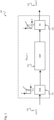
- ROF distortion is denoted by ⁇ ROF ( ⁇ ) as shown in Figure 1 which illustrates ROF channel's distortion.
- signal x RF (t) 104 excites a directly modulated laser (DML) 101.
- Output signal of laser 101 passes single mode fiber (SMF) 102 after which post-distortion (PD) 103 provides signal y RF (t) 105.
- SMF single mode fiber
- PD post-distortion
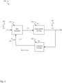
- the DPD degradation can be explained with help of Figure 2 , where s(f), 204 is the desired signal, x ( t ), 207 is the pre-distorted signal, y '( t ), 206 is the feedback signal, y ( t ), 205 is the transmitted signal.
- ⁇ ( ⁇ ) is used to denote the nonlinear system 202, such like power-amplifier, and ⁇ ( ⁇ ) to denote the feedback channel 203, like ROF channel.
- the truly transmit signal y(t) 205 is close to ⁇ -1 ( s ), which is distorted version of s ( t ), 204.
- the dispersion chromatic module (DCM) consists of using passive optic device that compensates the chromatic dispersion introduced in fiber transmission. It operates with optic signal and has proven effective for the non-linear behaviour of analogue ROF. However, this device is relatively expensive and in practice it must be adapted to specific fiber in use, for example 20km 1550m. Moreover, the use of DCM will introduce the attenuation of optic signal's strength that is definitely not wished in real network design.
- This method is composed of: (1) RRU 300 sends a training signal that can approximate the statistical behaviour of the ROF input signal 314; (2) central unit performs nonlinear system identification by using the known training signal; (3) perform non-linear post-distortion 301 on the received signal 313 for both UL 323 and feedback 324 use.
- the disadvantages of such post-equalization method are, in order to send the training signal from RRU sides 300, it is required first the use of large memory to store the digital signal, then DAC 308 and RF signal modulation with respect to the feedback RF signal 324 center frequency requires additional hardware. Moreover, the LO fed to up-converter 309 needs to be perfectly synchronized with LO of down-converter at central unit side.
- US2007171515 relates to electro-absorption duplexer.
- US5331453 relates to Millimeter wave fiber-optically linked antenna receiver device.
- US2003201839 relates to normalization methods for automatic frequency compensation in Bluetooth applications.
- US2005157814 relates to wideband enhanced digital injection pre-distortion system and method.
- ROF radio over fiber
- DPD digital predistortion
- a basic idea of the disclosure is to use a very compact radio remote unit (RRU) design by employing a simple stimulus signal generation with assumption that there is no knowledge of the stimulus sequence at the receiver side.
- RRU radio remote unit
- blind equalization is performed and the following system design, namely BPSK-aided post-distortion, is applied with a carrier signal (LO) modulated by a binary sequence randomly generated at RRU side.
- LO carrier signal
- the power of RF signal as input to uplink ROF (DML) is controlled by CU.
- DML uplink ROF
- the disclosure relates to a remote radio unit, RRU, comprising: a binary phase shift keying, BPSK, modulator, configured to modulate a BPSK waveform by a local oscillator, LO, signal to generate a stimulus signal, wherein the LO signal is derived from a downlink optical signal received via downlink radio over fiber, DL-ROF, from a central unit, CU; and an optical signal generator, in particular a laser, configured to generate an uplink optical signal based on the stimulus signal for transmission via uplink radio over fiber, UL-ROF, to the CU.
- BPSK binary phase shift keying
- RRU design can be implemented at reduced hardware complexity and costs.
- the RRU design can implement radio over fiber (ROF) systems, in particular ROF systems using digital predistortion (DPD) and feedback.
- ROF radio over fiber
- DPD digital predistortion
- Such a RRU can be implemented by a compact and low-cost RRU design, the same stimulus signal can be reused for multiple/massive MIMO case.
- the RRU design provides a high quality UL-ROF channel and a high quality feedback ROF channel for DPD application.
- simple equalization algorithms can be implemented. Besides, there are no-extra ROF link requirement for TDD system and on-line calibration for adaptive ROF deployment.
- a power of the uplink optical signal is controlled by the CU via control channel.
- the RRU comprises a band pass filter, BPF, configured to retrieve the LO signal from the downlink optical signal.
- BPF band pass filter
- band pass filter can filter out harmonics of the received signal due to non-linear distortions of the channel.
- the downlink optical signal carries the LO signal of carrier frequency fc and harmonics of the carrier frequency fc.
- the downlink optical signal can be used as control signal for the BPSK modulator as it carries information about the carrier frequency fc from the CU.
- the transmission efficiency is improved, as less resources are used.
- a pass band frequency range of the BPF includes the carrier frequency fc.
- the RRU comprises a pseudo-random binary sequence, PRBS, generator or a white noise generator configured to generate the BPSK waveform.
- the RRU is operated in time division duplex, TDD, mode, a downlink, DL, phase of the TDD mode is used for reception of the DL optical signal via DL-ROF, an uplink, UL, phase of the TDD mode is used for transmission of the UL optical signal via UL-ROF, and a DL/UL or UL/DL switch interval is used for training and/or calibration.
- TDD time division duplex
- a downlink, DL phase of the TDD mode is used for reception of the DL optical signal via DL-ROF
- an uplink, UL phase of the TDD mode is used for transmission of the UL optical signal via UL-ROF
- a DL/UL or UL/DL switch interval is used for training and/or calibration.
- the disclosure relates to a central unit, CU, comprising: an optical signal generator, in particular a laser, configured to generate a downlink optical signal based on a downlink digital signal for transmission via downlink radio over fiber, DL-ROF, to a radio remote unit, RRU; a digital pre-distorter, DPD, configured to digitally pre-distort the downlink digital signal based on a DPD feedback signal; and a blind linear digital channel equalizer, configured to provide the DPD feedback signal based on an uplink optical signal received via uplink radio over fiber, UL-ROF, from the RRU.
- an optical signal generator in particular a laser
- DPD digital pre-distorter
- DPD digitally pre-distort the downlink digital signal based on a DPD feedback signal
- a blind linear digital channel equalizer configured to provide the DPD feedback signal based on an uplink optical signal received via uplink radio over fiber, UL-ROF, from the RRU.
- Such a CU can be implemented by a compact and low-cost CU design, the same stimulus signal can be reused for multiple/massive MIMO case.
- the CU design provides a high quality UL-ROF channel and a high quality feedback ROF channel for DPD application. Simple equalization algorithms can be implemented. Besides, there are no-extra ROF link requirement for TDD system and on-line calibration for adaptive ROF deployment.
- the CU is configured to apply a decision-directed least-mean-squares, DD-LMS, algorithm on an uplink digital signal derived from the uplink optical signal to determine equalization coefficients of the blind linear digital channel equalizer.
- DD-LMS decision-directed least-mean-squares
- Such a CU can implement simple equalization algorithms such as the DD-LMS, reducing hardware (and/or software) complexity.
- the CU is configured to vary a gain of the uplink optical signal generated at the RRU via a control channel with the RRU to identify a non-linear distortion introduced by the UL-ROF.
- the CU is configured to identify an amplitude-to-amplitude modulation, AM-AM, response of the UL-ROF based on the gain variation of the uplink optical signal.
- the CU is configured to identify the non-linear distortion introduced by the UL-ROF based on an approximation as a memory-less non-linear system, in particular by an N-L or Hammerstein model.
- the CU is operated in time division duplex, TDD, mode, a downlink, DL, phase of the TDD mode is used for transmission of the DL optical signal via DL-ROF, an uplink, UL, phase of the TDD mode is used for reception of the UL optical signal via UL-ROF, and a DL/UL or UL/DL switch interval is used for training and/or calibration.
- TDD time division duplex
- a downlink, DL phase of the TDD mode is used for transmission of the DL optical signal via DL-ROF
- an uplink, UL phase of the TDD mode is used for reception of the UL optical signal via UL-ROF
- a DL/UL or UL/DL switch interval is used for training and/or calibration.
- the CU is configured to send a local oscillator, LO, signal of carrier frequency fc via the DL-ROF to the RRU.
- the disclosure relates to a multiple-input multiple-output, MIMO, system, comprising: a central unit, CU, according to the second aspect described above; and a remote radio unit, RRU, according to the first aspect described above, coupled to the CU by a single mode fiber, SMF.
- MIMO multiple-input multiple-output
- Such a MIMO system can be efficiently implemented by a compact and low-cost RRU and CU design, the same stimulus signal can be reused for multiple/massive MIMO case.
- the MIMO system provides a high quality UL-ROF channel and a high quality feedback ROF channel for DPD application. Simple equalization algorithms can be implemented. Besides, there are no-extra ROF link requirement for TDD system and on-line calibration for adaptive ROF deployment.
- the disclosure relates to a method for generating an uplink optical signal by a remote radio unit, RRU, the method comprising: receiving a downlink optical signal received via downlink radio over fiber, DL-ROF, from a central unit, CU; generating a stimulus signal based on a binary phase shift keying, BPSK, modulation of a BPSK waveform by a local oscillator, LO, signal, wherein the LO signal is derived from the downlink optical signal; and generating, by an optical signal generator, in particular a laser, an uplink optical signal based on the stimulus signal for transmission via uplink radio over fiber, UL-ROF, to the CU.
- BPSK binary phase shift keying
- LO local oscillator
- Such a method can be easily implemented by a compact and low-cost RRU and CU design, the same stimulus signal can be reused for multiple/massive MIMO case.
- the method provides a high quality UL-ROF channel and a high quality feedback ROF channel for DPD application.
- the disclosure relates to a method for generating a downlink optical signal by a central unit, CU, the method comprising: generating, by an optical signal generator, in particular a laser, a downlink optical signal based on a downlink digital signal for transmission via downlink radio over fiber, DL-ROF, to a radio remote unit, RRU; digitally pre-distorting, by a digital pre-distorter, DPD, the downlink digital signal based on a DPD feedback signal; and providing, by a blind linear digital channel equalizer, the DPD feedback signal based on an uplink optical signal received via uplink radio over fiber, UL-ROF, from the RRU.
- Such a method can be easily implemented with a compact and low-cost CU and RRU design, the same stimulus signal can be reused for multiple/massive MIMO case.
- the method provides a high quality UL-ROF channel and a high quality feedback ROF channel for DPD application. Simple equalization algorithms can be implemented.
- the disclosure relates to a computer program product including computer executable code or computer executable instructions that, when executed, causes at least one computer to execute the method according to the fourth or fifth aspect.
- a computer program product may include a non-transient readable storage medium storing program code thereon for use by a processor, the program code comprising instructions for performing the methods or the computing blocks as described hereinafter.
- the methods, devices and systems described herein may particularly be implemented in radio over fiber (ROF) communications using remote radio units and central units.
- ROF radio over fiber
- Radio over fiber refers to a technology whereby light is modulated by a radio frequency signal and transmitted over an optical fiber link.
- Main technical advantages of using fiber optical links are lower transmission losses and reduced sensitivity to noise and electromagnetic interference compared to all-electrical signal transmission.
- Applications range from the transmission of mobile radio signals (e.g. 3G, 4G, 5G and WiFi), the transmission of cable television signal and satellite communications.
- radio signals are carried over fiber-optic cable.
- a single antenna can receive any and all radio signals (5G, Wifi, cell, etc..) carried over a single-fiber cable to a central location where equipment then converts the signals.
- a remote radio unit also called a remote radio head (RRH) in wireless networks, is a remote radio transceiver that connects to an operator radio control panel via electrical or wireless interface.
- the radio equipment is remote to the BTS/NodeB/eNodeB/gNodeB (also referred to as the central unit).
- the equipment is used to extend the coverage of a BTS/NodeB/eNodeB/gNodeB in challenging environments such as rural areas or tunnels. They are generally connected to the BTS/NodeB/eNodeB/gNodeB via a fiber optic cable using Common Public Radio Interface protocols.
- RRUs have become one of the most important subsystems of today's new distributed base stations.
- the RRU contains the base station's RF circuitry plus analog-to-digital/digital-to-analog converters and up/down converters.
- RRUs also have operation and management processing capabilities and a standardized optical interface to connect to the rest of the base station.
- Remote radio units make MIMO operation easier; they increase a base station's efficiency and facilitate easier physical location for gap coverage problems.
- the methods, devices and systems described herein may particularly utilize PRBS and BPSK generators.
- a pseudorandom binary sequence is a binary sequence that, while generated with a deterministic algorithm, is difficult to predict and exhibits statistical behavior similar to a truly random sequence.
- Pseudorandom binary sequences can be generated using linear feedback shift registers.
- BPSK binary phase shift keying
- PSK phase shift keying
- the described devices may include integrated circuits and/or passives and may be manufactured according to various technologies.
- the circuits may be designed as logic integrated circuits, analog integrated circuits, mixed signal integrated circuits, optical circuits, memory circuits and/or integrated passives.
- the devices and systems described herein may include processors or processing devices, memories and transceivers, i.e. transmitters and/or receivers.
- processors or processing devices memories and transceivers, i.e. transmitters and/or receivers.
- processors or processing devices describes any device that can be utilized for processing specific tasks (or blocks or steps).
- a processor or processing device can be a single processor or a multi-core processor or can include a set of processors or can include means for processing.
- a processor or processing device can process software or firmware or applications etc.
- Fig. 4 shows a block diagram of a MIMO system 400 with Central Unit (CU) 410 and Radio Remote Unit (RRU) 420 applying BPSK-aided post-distortion according to the disclosure.
- CU Central Unit
- RRU Radio Remote Unit
- Such a multiple-input multiple-output (MIMO) system 400 comprises a central unit 410 and a remote radio unit, RRU 420 that is coupled to the CU by a single mode fiber, SMF.
- MIMO multiple-input multiple-output
- the RRU 420 comprises a binary phase shift keying, BPSK, modulator 422 that is configured to modulate a BPSK waveform 423 by a local oscillator, LO, signal 426 to generate a stimulus signal 325.
- the LO signal 426 is derived from a downlink optical signal 313 (e.g. as shown in Fig. 3 ) received via downlink radio over fiber, DL-ROF 401, from the central unit, CU 410.
- the RRU 420 further comprises an optical signal generator 312, e.g. a laser (or a photo-diode) that is configured to generate an uplink optical signal 314 (e.g. as shown in Fig. 3 ) based on the stimulus signal 325 for transmission via uplink radio over fiber, UL-ROF 402, to the CU 410.
- an optical signal generator 312 e.g. a laser (or a photo-diode) that is configured to generate an uplink optical signal 314 (e.g
- a power of the uplink optical signal 314 may be controlled by the CU 410 via a control channel (represented as the dashed line between CU 410 and RRU 420 in Fig. 4 ).
- the RRU 420 may comprise a band pass filter, BPF (e.g. a BPF 503 as shown in Fig. 5 ) that is configured to retrieve the LO signal 426 from the downlink optical signal 313.
- BPF band pass filter
- the downlink optical signal 313 may carry the LO signal 426 of carrier frequency fc and harmonics of the carrier frequency fc.
- a pass band frequency range of the BPF 503 may include the carrier frequency fc.
- the RRU 420 may further include a pseudo-random binary sequence, PRBS, generator 421 or a white noise generator that is configured to generate the BPSK waveform 423.
- the RRU 420 may be operated in time division duplex, TDD, mode, e.g. as illustrated in Fig. 10 .
- TDD time division duplex
- a downlink, DL, phase of the TDD mode may be used for reception of the DL optical signal 313 via DL-ROF 401
- an uplink, UL, phase of the TDD mode may be used for transmission of the UL optical signal 314 via UL-ROF 402
- a DL/UL or UL/DL switch interval may be used for training and/or calibration, e.g. as described below with respect to Fig. 10 .
- the CU 410 comprises an optical signal generator 414, e.g. a laser (or a photo-diode) that is configured to generate a downlink optical signal, e.g. a signal 610 as shown in Fig. 6 , based on a downlink digital signal 416 for transmission via downlink radio over fiber, DL-ROF 401, to the RRU 420.
- the CU 410 further includes a digital pre-distorter, DPD 412, that is configured to digitally pre-distort the downlink digital signal 416 based on a DPD feedback signal 419.
- the CU 410 further includes a blind linear digital channel equalizer 417 that is configured to provide the DPD feedback signal 419 based on an uplink optical signal, e.g. signal 611 shown in Fig. 6 , received via uplink radio over fiber, UL-ROF 402, from the RRU 420.
- a blind linear digital channel equalizer 417 that is configured to provide the DPD feedback signal 419 based on an uplink optical signal, e.g. signal 611 shown in Fig. 6 , received via uplink radio over fiber, UL-ROF 402, from the RRU 420.
- the CU 410 may be configured to apply a decision-directed least-mean-squares, DD-LMS, algorithm on an uplink digital signal derived from the uplink optical signal 611 to determine equalization coefficients of the blind linear digital channel equalizer 417.
- DD-LMS decision-directed least-mean-squares
- the CU 410 may be configured to vary a gain of the uplink optical signal 611 generated at the RRU 420 via a control channel with the RRU 420 to identify a non-linear distortion introduced by the UL-ROF 402.
- the CU 410 may be configured to identify an amplitude-to-amplitude modulation, AM-AM, response (e.g. determined by AM-AM compensator 609 shown in Fig. 6 ) of the UL-ROF 402 based on the gain variation of the uplink optical signal 611.
- AM-AM amplitude-to-amplitude modulation
- the CU 410 may be configured to identify the non-linear distortion introduced by the UL-ROF 402 based on an approximation as a memory-less non-linear system, in particular by an N-L or Hammerstein model.
- the Hammerstein model is a special model form for non-linear dynamic systems named after Adolf Hammerstein. Characteristic is the structure consisting of the series connection of a static non-linearity in front of a linear time-invariant dynamic system. The Hammerstein model is defined for both single and multi-size systems.
- the CU 410 may be operated in time division duplex, TDD, mode, e.g. as illustrated in Fig. 10 .
- TDD time division duplex
- a downlink, DL, phase of the TDD mode may be used for transmission of the DL optical signal via DL-ROF
- an uplink, UL, phase of the TDD mode may be used for reception of the UL optical signal via UL-ROF
- a DL/UL or UL/DL switch interval may be used for training and/or calibration, e.g. as described below with respect to Fig. 10 .
- the CU 410 may be configured to send a local oscillator, LO, signal of carrier frequency fc via the DL-ROF 401 to the RRU 420.
- the MIMO system 400 shown in Fig. 4 can be implemented with a very compact radio remote unit (RRU) design by employing a simple stimulus signal generation with assumption that there is no knowledge of the stimulus sequence at the receiver side.
- RRU radio remote unit
- blind equalization is performed and the following system design, namely BPSK-aided post-distortion, is applied with a carrier signal (LO) modulated by a binary sequence randomly generated at RRU side.
- LO carrier signal
- the power of RF signal as input to uplink ROF (DML) is controlled by CU.
- the MIMO system 400 design can be characterized by the following features:
- Fig. 5 shows a block diagram of a remote radio unit (RRU) 500 configured to apply BPSK-aided blind equalization according to the disclosure.
- the RRU 500 represents an implementation of the RRU 420 described above with respect to Fig. 4 .
- the optic signal 313 received from SMF i.e. via DL-ROF 401 as described above with respect to Fig. 4 passes post-distortion module (PD) 301 and power amplifier (PA) 302.
- PD 301 the received signal can be represented by a carrier frequency component and a plurality of harmonics.
- PA 302 the receive signal after PA 302 branches to a first branch with attenuator 303 that provides feedback signal x(t) 526 that is forwarded via first sub-branch to modulator switch 306 and via second sub-branch to bandpass filter (BPF) 503 and to BPSK modulator 422.
- the receive signal after PA 302 branches to a second branch with antenna switch 304 where it is switched to antenna 305 and as uplink signal 323 to modulator switch 306.
- BPSK modulator 422 is fed by a modulation waveform 423 that is generated by a BPSK generator 501.
- the BPF 503 is configured to filter out the carrier frequency component from the plurality of harmonics of the received optical signal 313. This carrier frequency component controls the BPSK modulator 422.
- the generated output signal is passed to a variable gain amplifier (VGA) 310 controlling a gain g of the output signal. Via a control channel (not depicted in Fig. 5 ) the gain can be controlled 311 by the CU 410.
- the amplified output signal is used to excite the optical generator 312, i.e. directly modulated laser 312 that generates the optic signal 314 fed to SMF 403 for transmission via UL/FB-ROF 402 as shown in Fig. 4 .
- a LO signal is sent by CU 410 via DL-ROF 401, denoted by x RF,DL ( t ) in Fig. 6 that describes a CU implementation 600.
- the received signal y DL,RRU ( t ) 313 (output of DL-ROF 401) or y' DL, RRU ( t ) (PA output) is actually the LO signal and its harmonics, considering the non-linear effect of DL-ROF 401 and PA 302.
- This RF signal is then fed to BPSK modulator 422, after the filtering the harmonics by using BPF 503 for f c (Band Pass Filter), the CU's LO can be perfectly recovered. Since the LO and its harmonics are far spaced in frequency domain, for example 3.5GHz, the BPF 503 is easy to design.
- the benefit of using CU forwarded LO signal is this can effectively remove the carrier-frequency offset (CFO). The linear or non-linear distortion are all mitigated as well.
- the BPSK sequence or baseband waveform generator 501 is installed and the generated sequence 423 is not necessarily known to CU 410.
- This BPSK signal generator 501 can be either a PRBS (pseudo-random binary sequence) generator or filtered white noise generator.
- PRBS pseudo-random binary sequence
- the interesting part is the simplified RRU design 500 since the random binary sequence generator 501, the BPSK modulator 422 and the filter can be implemented as cheap and compact units (hardware circuits), e.g. by using standard integrated circuits.
- the modulated RF signal denoted by r RF ( t ) is amplified by a gain g, controlled by CU 410 via low-rate digital control.
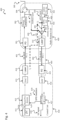
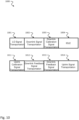
- Fig. 6 shows a block diagram of a central unit (CU) 600 configured to apply BPSK-aided blind equalization according to the disclosure.
- the CU 600 represents an implementation of the CU 410 described above with respect to Fig. 4 . It can be combined with the RRU design 500 described above with respect to Fig. 5 to a MIMO system as shown in Fig. 4 .
- a digital input signal 416 is passed to digital pre-distortion (DPD) unit 412.
- the output of DPD 412 passes digital-to-analogue converter (DAC) 413 and upconverter 603 before it excites a directly modulated laser (DML) 414 (i.e. optical signal generator) to generate optic signal 610 to SMF.
- optic signal 611 is received from SMF 403 (see Fig. 4 ) and passes post-distortion (PD) unit 414, down-converter (D/C) 606, analogue-to-digital converter (ADC) 416 where it is converted to a digital receive signal u BB (n).
- This digital receive signal u BB (n) is input to blind channel compensator 417 using for example DD-LMS training algorithm.
- AM-AM compensation block 609 compensated digital signal 419 is used to control DPD 412.
- blind channel equalization such like decision-directed least-mean-square (DD-LMS) algorithm is executed to find the linear equalizer's coefficients. Then, the gain applied on r RF ( t ) 325 (see Fig. 5 ) is varied to identify the nonlinear distortion.
- This processing can be detailed as follows:
- h UL,CU ( t ) denotes the linear distortion introduced at CU 410, 600 (LNA, mixer, LPF, ADC, etc.)
- ⁇ UL,ROF ( ⁇ ) denotes the nonlinear distortion introduced by UL-ROF 402. Note that the linear distortion at RRU side 420 can be omitted since typically BPSK modulator 422 exhibits less linear distortion (on RF signal) compared with conventional up-conversion approach.
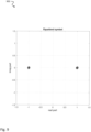
- ⁇ UL,ROF ( ⁇ ) can be approximated as a memory-less non-linear system, see “ E. E. Bergamann, "Dispersion-Induced Compmosite Second-Order Distortion at 1.5um,” IEEE PHOTONICS TECHNOLOGY LETTER VOL 3 NO1, 1991 ", the ⁇ UL,ROF ( ⁇ ) can be described by using an AM-AM model 700 as shown in Fig. 7 (equivalent to the absolute value of the complex baseband signal) such that the feedback ROF channel can be approximated by an N-L or Hammerstein model.
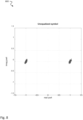
- Fig. 7 shows a performance diagram 700 illustrating the memoryless non-linear effect for AM-AM.
- Graph 702 represents the non-linear system that can be approximated as linear system (depicted by graph 701). A good approximation can be obtained for input values between 0 and 0.5 while a still acceptable approximation can be obtained for input values between 0.5 and 1. Thus the non-linear system can be approximated as memoryless.
- Fig. 8 shows a symbol diagram 800 in the complex plane for unequalized ROF transmission
- Fig. 9 shows a symbol diagram 900 in the complex plane for equalized ROF transmission using BPSK-aided equalization according to the disclosure.
- the ROF non-linear distortion ⁇ UL,ROF will not impact the compensation on linear distortion as h UL,CU is compensated: a BPSK waveform after memoryless non-linear distortion is still a BPSK waveform.
- the conventional blind equalization technique DD-LMS can be used to compensate h UL,CU and then identify the AM-AM response of ⁇ UL,ROF by varying the VGA gain g at RRU via control channel.
- the calibration is the inverse of ⁇ UL,ROF .
- the symbol diagrams 800 and 900 show that the feedback signal quality can be effectively improved.
- Figures 8 and 9 are examples for a 20km ROF transmission where the EVM is improved from 4.78% to 2.41%.
- Fig. 10 shows a schematic diagram of a TDD system 1000 illustrating TDD operation and ROF channel calibration according to the disclosure.
- the calibration of UL/DL-ROF has been designed for a time division duplex (TDD) system 1000 as shown in Figure 10 .
- the time intervals 1002, 1012 are used for downlink signal transportation and downlink feedback signal transportation while time intervals 1004 and 1014 are used as IDLE state and for uplink signal transportation, i.e. according to a usual TDM system:
- the DL/UL 1003, 1013 or UL/DL 1001, 1011 switch interval can be used for dedicated calibration:
- the calibration procedure can be executed in an adaptive filter manner, the post-distortion can track the quick variation of the environment so compared with conventional off-line training method, this approach is more suitable for on-line calibration.
- Fig. 11 shows a schematic diagram illustrating a method for generating an uplink optical signal by a remote radio unit (RRU) according to the disclosure, for example by a RRU as described above with respect to Figures 4 and 5 .
- RRU remote radio unit
- the method 1100 comprises receiving 1101 a downlink optical signal received via downlink radio over fiber, DL-ROF, from a central unit, CU, e.g. a CU as described above with respect to Figures 4 and 6 .
- a central unit e.g. a CU as described above with respect to Figures 4 and 6 .
- the method 1100 comprises generating 1102 a stimulus signal based on a binary phase shift keying, BPSK, modulation of a BPSK waveform by a local oscillator, LO, signal, wherein the LO signal is derived from the downlink optical signal, e.g. as described above with respect to Figures 4 and 5 .
- BPSK binary phase shift keying
- LO local oscillator
- the method 1100 comprises generating 1103, by an optical signal generator, in particular a laser, an uplink optical signal based on the stimulus signal for transmission via uplink radio over fiber, UL-ROF, to the CU, e.g. as described above with respect to Figures 4 and 5 .
- Fig. 12 shows a schematic diagram illustrating a method for generating a downlink optical signal by a central unit (CU) according to the disclosure, for example by a CU as described above with respect to Figures 4 and 6 .
- CU central unit
- the method 1200 comprises generating 1201, by an optical signal generator, in particular a laser, a downlink optical signal based on a downlink digital signal for transmission via downlink radio over fiber, DL-ROF, to a radio remote unit, RRU, e.g. a RRU as described above with respect to Figures 4 and 5 .
- an optical signal generator in particular a laser
- a downlink optical signal based on a downlink digital signal for transmission via downlink radio over fiber, DL-ROF to a radio remote unit, RRU, e.g. a RRU as described above with respect to Figures 4 and 5 .
- the method 1200 comprises digitally pre-distorting 1202, by a digital pre-distorter, DPD, the downlink digital signal based on a DPD feedback signal, e.g. as described above with respect to Figures 4 and 6 .
- the method 1200 comprises providing 1203, by a blind linear digital channel equalizer, the DPD feedback signal based on an uplink optical signal received via uplink radio over fiber, UL-ROF, from the RRU, e.g. as described above with respect to Figures 4 and 6 .
- the present disclosure also supports a computer program product including computer executable code or computer executable instructions that, when executed, causes at least one computer to execute the performing and computing steps described herein, in particular the methods and procedures described above.
- a computer program product may include a readable non-transitory storage medium storing program code thereon for use by a computer.
- the program code may perform the processing and computing steps described herein, in particular the methods and procedures described above.
Landscapes
- Engineering & Computer Science (AREA)
- Signal Processing (AREA)
- Computer Networks & Wireless Communication (AREA)
- Physics & Mathematics (AREA)
- Electromagnetism (AREA)
- Optics & Photonics (AREA)
- Optical Communication System (AREA)
Claims (12)
- Entfernte Funkeinheit, RRU (420), umfassend ein Bandpassfilter, BPF (503), einen Binärphasenumtastungsmodulator, BPSK-Modulator (422), einen Verstärker mit variabler Verstärkung (310) und einen Generator für optische Signale (312), wobei:das BPF (503) dazu konfiguriert ist, ein Lokaloszillatorsignal, LO-Signal (426), aus einem optischen Downlink-Signal (313) abzuleiten, das über Downlink-Radio-over-Fiber, DL-ROF (401), von einer Zentraleinheit, CU (410), empfangen wirdder BPSK-Modulator (422) dazu konfiguriert ist, eine BPSK-Wellenform (423) auf das LO-Signal (426) zu modulieren, um ein Stimulus-Signal (325) zu generieren und das Stimulus-Signal dem Verstärker mit variabler Verstärkung (310) bereitzustellen,der Verstärker mit variabler Verstärkung (310) dazu konfiguriert ist, eine Verstärkung auf das Stimulus-Signal anzuwenden und das Stimulus-Signal nach der Verstärkung dem Generator für optische Signale bereitzustellen;der Generator für optische Signale (312) dazu konfiguriert ist, ein zu übertragendes optisches Uplink-Signal (314) basierend auf dem Stimulus-Signal (325) zur Übertragung über Uplink-Radio-over-Fiber, UL-ROF (402), an die CU (410) zu generieren und das zu übertragende optische Uplink-Signal an die CU (410) zu übertragen;wobei: ein empfangenes optisches Uplink-Signal, das dem zu übertragenden optischen Signal entspricht, durch die folgende Gleichung definiert ist:
 wobei uBB eine digitale Basisbanddarstellung des empfangenen optischen Uplink-Signals (611) bezeichnet, hUL,CU eine lineare Verzerrung bezeichnet, die an der CU (410) eingeführt wird, Φ UL,ROF eine nichtlineare Verzerrung bezeichnet, die durch das UL-ROF (402) eingeführt wird, g eine Verstärkung bezeichnet, die durch den Verstärker mit variabler Verstärkung auf das Stimulus-Signal angewendet wird, rBB eine digitale Basisbanddarstellung der BPSK-Wellenform bezeichnet und nBB ein Verzerrungssignal bezeichnet,wobei der Verstärker mit variabler Verstärkung (310) ferner dazu konfiguriert ist, über einen Steuerkanal ein Steuersignal mit variierender Verstärkung, das durch die CU (410) gesendet wird, zu empfangen und eine Verstärkung zu variieren, die auf das Stimulus-Signal als Reaktion auf eine Variation des Verstärkungssteuersignals angewendet wird, wodurch die CU (410) in die Lage versetzt wird, eine Amplituden-zu-Amplituden-Modulations-Reaktion, AM-AM-Reaktion (609), des UL-ROF (402) zu identifizieren und ferner eine nichtlineare Verzerrung zu identifizieren, die durch das UL-ROF (402) eingeführt wird.
 - RRU (420) nach Anspruch 1, umfassend:
ein Bandpassfilter, BPF (503), das dazu konfiguriert ist, das LO-Signal (426) aus dem optischen Downlink-Signal (313) abzurufen. - RRU (420) nach Anspruch 2,
wobei das optische Downlink-Signal (313) das LO-Signal (426) von Trägerfrequenz fc und Harmonische der Trägerfrequenz fc beinhaltet. - RRU (420) nach Anspruch 3,
wobei ein Durchlassfrequenzbereich des BPF (503) die Trägerfrequenz fc beinhaltet. - RRU (420) nach einem der Ansprüche 1-4, betrieben im Zeitduplexmodus, TDD-Modus (1000),
wobei eine Downlink-Phase, DL-Phase, des TDD-Modus zum Empfang des optischen DL-Signals (313) über DL-ROF (401) verwendet wird, wobei eine Uplink-Phase, UL-Phase, des TDD-Modus zur Übertragung des optischen UL-Signals (314) über UL-ROF (402) verwendet wird, wobei ein DL/UL- oder UL/DL-Umschaltintervall zum Training und/oder zur Kalibrierung verwendet wird. - Zentraleinheit, CU (410), umfassend:einen Generator für optische Signale (414), der dazu konfiguriert ist, ein optisches Downlink-Signal (610) basierend auf einem digitalen Downlink-Signal (416) zur Übertragung über Downlink-Radio-over-Fiber, DL-ROF (401), an eine entfernte Funkeinheit, RRU (420), zu generieren;einen digitalen Vorverzerrer, DPD (412), der dazu konfiguriert ist, das digitale Downlink-Signal (416) basierend auf einem DPD-Rückkopplungssignal (419) digital vorzuverzerren; undeinen blinden linearen digitalen Kanalentzerrer (417), der dazu konfiguriert ist, das DPD-Rückkopplungssignal (419) basierend auf einem optischen Uplink-Signal (611) bereitzustellen, das über Uplink-Radio-over-Fiber, UL-ROF (402), von der RRU (420) empfangen wird;wobei die CU (410) ferner dazu konfiguriert ist:eine Verstärkung des optischen Uplink-Signals (611), das an der RRU (420) generiert wird, über einen Steuerkanal mit der RRU (420) zu variieren, um eine Amplituden-zu-Amplituden-Modulations-Reaktion, AM-AM-Reaktion (609), des UL-ROF (402) basierend auf der Verstärkungsvariation des optischen Uplink-Signals (611) zu identifizieren und ferner eine nichtlineare Verzerrung zu identifizieren, die durch das UL-ROF (402) eingeführt wird;wobei die CU (410) ferner dazu konfiguriert ist, den blinden linearen digitalen Kanalentzerrer (417) basierend auf der folgenden Beziehung einzustellen:
 wobei uBB eine digitale Basisbanddarstellung des optischen Uplink-Signals (611) bezeichnet, hUL,CU eine lineare Verzerrung bezeichnet, die an der CU (410) eingeführt wird, Φ UL,ROF eine nichtlineare Verzerrung bezeichnet, die durch das UL-ROF (402) eingeführt wird, g eine Verstärkung des optischen Uplink-Signals (611), das an der RRU (420) generiert wird, bezeichnet, rBB eine digitale Basisbanddarstellung einer BPSK-Wellenform an der RRU (420) bezeichnet, die zum Generieren des optischen Uplink-Signals (611) verwendet wird, und nBB ein Verzerrungssignal bezeichnet.
 - CU (410) nach Anspruch 6, die zu Folgendem konfiguriert ist: Anwenden eines entscheidungsorientierten Least-Mean-Square-Algorithmus, DD-LMS-Algorithmus, auf ein digitales Uplink-Signal, das aus dem optischen Uplink-Signal (611) abgeleitet wird, um Entzerrungskoeffizienten des blinden linearen digitalen Kanalentzerrers (417) zu bestimmen.
- CU (410) nach einem der Ansprüche 6 oder 7, die zu Folgendem konfiguriert ist:
Senden eines Lokaloszillatorsignals, LO-Signals, mit der Trägerfrequenz fc über das DL-ROF (401) an die RRU (420). - CU (410) nach einem der Ansprüche 6 bis 8, die zu Folgendem konfiguriert ist:
wobei das optische Downlink-Signal (313) das LO-Signal (426) von Trägerfrequenz fc und Harmonische der Trägerfrequenz fc beinhaltet. - CU (410) nach einem der Ansprüche 6 bis 9, betrieben im Zeitduplexmodus, TDD-Modus (1000),wobei eine Downlink-Phase, DL-Phase, des TDD-Modus zur Übertragung des optischen DL-Signals über DL-ROF verwendet wird,wobei eine Uplink-Phase, UL-Phase, des TDD-Modus zum Empfang des optischen UL-Signals über UL-ROF verwendet wird,wobei ein DL/UL- oder UL/DL-Umschaltintervall zum Training und/oder zur Kalibrierung verwendet wird.
- Verfahren (1100) zum Generieren eines optischen Uplink-Signals durch eine entfernte Funkeinheit, RRU, wobei das Verfahren Folgendes umfasst:Modulieren einer BPSK-Wellenform (423) auf ein Lokaloszillatorsignal, LO-Signal (426), um ein Stimulus-Signal (325) zu generieren, und Bereitstellen des Stimulus-Signals an den Verstärker mit variabler Verstärkung (310), wobei das LO-Signal (426) von einem optischen Downlink-Signal (313) abgeleitet wird, das über Downlink-Radio-over-Fiber, DL-ROF (401), von einer Zentraleinheit, CU (410), empfangen wird;Anwenden einer Verstärkung auf das Stimulus-Signal und Bereitstellen des Stimulus-Signals nach der Verstärkung an den Generator für optische Signale;Generieren eines zu übertragenden optischen Uplink-Signals (314) basierend auf dem Stimulus-Signal (325) zur Übertragung über Uplink-Radio-over-Fiber, UL-ROF (402), an die CU (410) und Übertragen des zu übertragenden optischen Uplink-Signals an die CU (410);wobei: ein empfangenes optisches Uplink-Signal, das dem zu übertragenden optischen Signal entspricht, durch die folgende Gleichung definiert ist:
 wobei uBB eine digitale Basisbanddarstellung des empfangenen optischen Uplink-Signals (611) bezeichnet, hUL,CU eine lineare Verzerrung bezeichnet, die an der CU (410) eingeführt wird, Φ UL,ROF eine nichtlineare Verzerrung bezeichnet, die durch das UL-ROF (402) eingeführt wird, g eine Verstärkung bezeichnet, die durch den Verstärker mit variabler Verstärkung auf das Stimulus-Signal angewendet wird, rBB eine digitale Basisbanddarstellung der BPSK-Wellenform bezeichnet und nBB ein Verzerrungssignal bezeichnet,wobei das Verfahren ferner Folgendes umfasst:
Empfangen, über einen Steuerkanal, eines Steuersignals mit variierender Verstärkung, das durch die CU (410) gesendet wird, und Variieren einer Verstärkung, die auf das Stimulus-Signal als Reaktion auf eine Variation des Verstärkungssteuersignals angewendet wird, wodurch die CU (410) in die Lage versetzt wird, eine Amplituden-zu-Amplituden-Modulations-Reaktion, AM-AM-Reaktion (609), des UL-ROF (402) zu identifizieren und ferner eine nichtlineare Verzerrung zu identifizieren, die durch das UL-ROF (402) eingeführt wird. - Verfahren (1200) zum Generieren eines optischen Downlink-Signals durch eine Zentraleinheit, CU, wobei das Verfahren Folgendes umfasst:Generieren eines optischen Downlink-Signals (610) basierend auf einem digitalen Downlink-Signal (416) zur Übertragung über Downlink-Radio-over-Fiber, DL-ROF (401), an eine entfernte Funkeinheit, RRU (420);digitales Vorverzerren des digitalen Downlink-Signals (416) basierend auf einem DPD-Rückkopplungssignal (419); undBereitstellen des DPD-Rückkopplungssignals (419) basierend auf einem optischen Uplink-Signal (611), das über Uplink-Radio-over-Fiber, UL-ROF (402), von der RRU (420) empfangen wird;wobei das Verfahren ferner Folgendes umfasst:Variieren einer Verstärkung des optischen Uplink-Signals (611), das an der RRU (420) generiert wird, über einen Steuerkanal mit der RRU (420), Identifizieren einer Amplituden-zu-Amplituden-Modulations-Reaktion, AM-AM-Reaktion (609), des UL-ROF (402) basierend auf der Verstärkungsvariation des optischen Uplink-Signals (611) und ferner Identifizieren einer nichtlinearen Verzerrung, die durch das UL-ROF (402) eingeführt wird; undEinstellen des blinden linearen digitalen Kanalentzerrers (417) basierend auf der folgenden Beziehung:
 wobei uBB eine digitale Basisbanddarstellung des optischen Uplink-Signals (611) bezeichnet, hUL,CU eine lineare Verzerrung bezeichnet, die an der CU (410) eingeführt wird, Φ UL,ROF eine nichtlineare Verzerrung bezeichnet, die durch das UL-ROF (402) eingeführt wird, g eine Verstärkung des optischen Uplink-Signals (611), das an der RRU (420) generiert wird, bezeichnet, rBB eine digitale Basisbanddarstellung einer BPSK-Wellenform an der RRU (420) bezeichnet, die zum Generieren des optischen Uplink-Signals (611) verwendet wird, und nBB ein Verzerrungssignal bezeichnet.
Applications Claiming Priority (1)
| Application Number | Priority Date | Filing Date | Title |
|---|---|---|---|
| PCT/EP2018/079432 WO2020083508A1 (en) | 2018-10-26 | 2018-10-26 | Remote radio unit and central unit for multiple-input multiple-output system |
Publications (3)
| Publication Number | Publication Date |
|---|---|
| EP3857740A1 EP3857740A1 (de) | 2021-08-04 |
| EP3857740C0 EP3857740C0 (de) | 2024-10-02 |
| EP3857740B1 true EP3857740B1 (de) | 2024-10-02 |
Family
ID=64051551
Family Applications (1)
| Application Number | Title | Priority Date | Filing Date |
|---|---|---|---|
| EP18795983.8A Active EP3857740B1 (de) | 2018-10-26 | 2018-10-26 | Entfernte funkeinheit und zentraleinheit für ein mimo-system |
Country Status (5)
| Country | Link |
|---|---|
| US (1) | US11563493B2 (de) |
| EP (1) | EP3857740B1 (de) |
| JP (1) | JP7155496B2 (de) |
| CN (1) | CN112913159B (de) |
| WO (1) | WO2020083508A1 (de) |
Families Citing this family (4)
| Publication number | Priority date | Publication date | Assignee | Title |
|---|---|---|---|---|
| EP4037207A1 (de) * | 2021-01-28 | 2022-08-03 | Nokia Solutions and Networks Oy | Funkgerät und -system |
| US12126364B2 (en) | 2021-08-18 | 2024-10-22 | Nec Corporation | Delta-sigma modulation apparatus, delta-sigma modulation method, and recording medium |
| WO2023021626A1 (ja) * | 2021-08-18 | 2023-02-23 | 日本電気株式会社 | 無線アクセスネットワーク装置、無線通信装置、方法及び記録媒体 |
| EP4434162A1 (de) * | 2021-11-17 | 2024-09-25 | Telefonaktiebolaget LM Ericsson (publ) | Verfahren zur übertragung von downlink-funksignalen in einem d-mimo-system und d-mimo-system |
Family Cites Families (19)
| Publication number | Priority date | Publication date | Assignee | Title |
|---|---|---|---|---|
| FR2445079A1 (fr) * | 1978-12-20 | 1980-07-18 | Ibm France | Procede et dispositif pour detecter une sequence pseudo-aleatoire de changements de phase de 0o et 180o de la porteuse dans un recepteur de donnees |
| US5331453A (en) * | 1992-06-15 | 1994-07-19 | Ael Defense Corp. | Millimeter wave fiber-optically linked antenna receiver device |
| JPH11355209A (ja) * | 1998-06-11 | 1999-12-24 | Toshiba Corp | 光アナログ伝送装置 |
| US6642797B1 (en) * | 2002-04-25 | 2003-11-04 | Agere Systems, Inc. | Normalization methods for automatic requency compensation in bluetooth applications |
| US7366252B2 (en) * | 2004-01-21 | 2008-04-29 | Powerwave Technologies, Inc. | Wideband enhanced digital injection predistortion system and method |
| KR100759805B1 (ko) * | 2005-12-07 | 2007-09-20 | 한국전자통신연구원 | 광증폭 듀플렉서 |
| JP5153507B2 (ja) | 2008-08-04 | 2013-02-27 | 三菱電機株式会社 | 無線通信装置 |
| CN102186264A (zh) * | 2011-04-12 | 2011-09-14 | 新邮通信设备有限公司 | 射频拉远单元及射频拉远方法 |
| EP2602948A1 (de) * | 2011-12-05 | 2013-06-12 | Alcatel Lucent | Verfahren zur Verarbeitung eines digitalen Übertragungssignals, Verfahren zur Verarbeitung einer optischen Dateneinheit nach Empfang und Netzwerkelement für ein Telekommunikationsnetzwerk |
| US9603032B2 (en) * | 2012-06-14 | 2017-03-21 | Advanced Rf Technologies, Inc. | System and method for automatically measuring uplink noise level of distributed antenna system |
| US9614629B2 (en) * | 2012-08-15 | 2017-04-04 | Commscope Technologies Llc | Telecommunication system using multiple Nyquist zone operations |
| US9306669B2 (en) * | 2012-08-28 | 2016-04-05 | Advanced Rf Technologies, Inc. | Optic distributed antenna system supporting multi-band multi-carrier service over a reduced number of optic core lines |
| US8958504B2 (en) * | 2012-09-07 | 2015-02-17 | Texas Instruments Incorporated | Carrier recovery in amplitude and phase modulated systems |
| EP2830382B1 (de) * | 2013-07-23 | 2016-03-23 | Alcatel Lucent | Verfahren zur drahtlosen Backhaul Kommunikation, Funkzugriffseinheit und zentrale Einheit dafür |
| JP2016536948A (ja) | 2013-11-04 | 2016-11-24 | ゼットティーイー コーポレーションZte Corporation | 光通信における適応的予等化 |
| EP3132651B1 (de) * | 2014-04-15 | 2018-10-17 | Telefonaktiebolaget LM Ericsson (publ) | Erster netzwerkknoten, zweiter netzwerkknoten und verfahren darin |
| CN105450373B (zh) * | 2014-08-22 | 2019-01-08 | 上海诺基亚贝尔股份有限公司 | 一种在前端回传网络上传输数据的方法及其设备 |
| US10659163B2 (en) * | 2014-09-25 | 2020-05-19 | Corning Optical Communications LLC | Supporting analog remote antenna units (RAUs) in digital distributed antenna systems (DASs) using analog RAU digital adaptors |
| WO2019228608A1 (en) | 2018-05-28 | 2019-12-05 | Huawei Technologies Co., Ltd. | A remote radio unit and a central unit for a base transceiver station |
-
2018
- 2018-10-26 CN CN201880098641.1A patent/CN112913159B/zh active Active
- 2018-10-26 EP EP18795983.8A patent/EP3857740B1/de active Active
- 2018-10-26 WO PCT/EP2018/079432 patent/WO2020083508A1/en not_active Ceased
- 2018-10-26 JP JP2021521509A patent/JP7155496B2/ja active Active
-
2021
- 2021-04-23 US US17/238,912 patent/US11563493B2/en active Active
Also Published As
| Publication number | Publication date |
|---|---|
| WO2020083508A1 (en) | 2020-04-30 |
| EP3857740A1 (de) | 2021-08-04 |
| CN112913159A (zh) | 2021-06-04 |
| CN112913159B (zh) | 2022-06-10 |
| EP3857740C0 (de) | 2024-10-02 |
| JP7155496B2 (ja) | 2022-10-19 |
| US11563493B2 (en) | 2023-01-24 |
| JP2022505466A (ja) | 2022-01-14 |
| US20210266070A1 (en) | 2021-08-26 |
Similar Documents
| Publication | Publication Date | Title |
|---|---|---|
| US11563493B2 (en) | Remote radio unit and central unit for multiple-input multiple-output system | |
| US10382132B2 (en) | Digital radio frequency transceiver system and method | |
| US8428525B2 (en) | Predistorter for a multi-antenna transmitter | |
| US11271651B2 (en) | Remote radio unit and a central unit for a base transceiver station | |
| EP3190720A1 (de) | Satellitentransponder-loopback-vorverzerrer | |
| Kim | RoF-based optical fronthaul technology for 5G and beyond | |
| US11909441B2 (en) | Base station and a method for operating the base station | |
| US11456762B2 (en) | Control device and radio communication device | |
| Hadi et al. | 5G NR MIMO enabled multiband fiber wireless system using analog optical front haul | |
| Mateo et al. | Digital predistortion of a full-duplex Radio-over-Fiber mobile fronthaul link with feedback loop | |
| US10158388B2 (en) | Receiver device and method for non-linear channel compensation | |
| Kim et al. | Blind compensation of nonlinear waveform distortions in radio-over-fiber system | |
| Mateo et al. | Experimental evaluation of the feedback loop effects in digital predistortion of a radio-over-fiber system | |
| Kasmi et al. | Influence of frequency mapping on intermodulation distortion in an SOA-based optical fronthaul C-RAN architecture for 5G communications | |
| Mateo et al. | Linearization of a radio-over-fiber mobile fronthaul with feedback loop | |
| Carro et al. | DPD linearization complexity reduction of remote radio heads in C-RAN with radio over fiber fronthaul | |
| Lozhkin et al. | Impact of radio over fiber links in feedback on linearization performances of RF power amplifiers |
Legal Events
| Date | Code | Title | Description |
|---|---|---|---|
| STAA | Information on the status of an ep patent application or granted ep patent |
Free format text: STATUS: UNKNOWN |
|
| STAA | Information on the status of an ep patent application or granted ep patent |
Free format text: STATUS: THE INTERNATIONAL PUBLICATION HAS BEEN MADE |
|
| PUAI | Public reference made under article 153(3) epc to a published international application that has entered the european phase |
Free format text: ORIGINAL CODE: 0009012 |
|
| STAA | Information on the status of an ep patent application or granted ep patent |
Free format text: STATUS: REQUEST FOR EXAMINATION WAS MADE |
|
| 17P | Request for examination filed |
Effective date: 20210426 |
|
| AK | Designated contracting states |
Kind code of ref document: A1 Designated state(s): AL AT BE BG CH CY CZ DE DK EE ES FI FR GB GR HR HU IE IS IT LI LT LU LV MC MK MT NL NO PL PT RO RS SE SI SK SM TR |
|
| DAV | Request for validation of the european patent (deleted) | ||
| DAX | Request for extension of the european patent (deleted) | ||
| GRAP | Despatch of communication of intention to grant a patent |
Free format text: ORIGINAL CODE: EPIDOSNIGR1 |
|
| STAA | Information on the status of an ep patent application or granted ep patent |
Free format text: STATUS: GRANT OF PATENT IS INTENDED |
|
| INTG | Intention to grant announced |
Effective date: 20240521 |
|
| GRAS | Grant fee paid |
Free format text: ORIGINAL CODE: EPIDOSNIGR3 |
|
| GRAA | (expected) grant |
Free format text: ORIGINAL CODE: 0009210 |
|
| STAA | Information on the status of an ep patent application or granted ep patent |
Free format text: STATUS: THE PATENT HAS BEEN GRANTED |
|
| AK | Designated contracting states |
Kind code of ref document: B1 Designated state(s): AL AT BE BG CH CY CZ DE DK EE ES FI FR GB GR HR HU IE IS IT LI LT LU LV MC MK MT NL NO PL PT RO RS SE SI SK SM TR |
|
| REG | Reference to a national code |
Ref country code: GB Ref legal event code: FG4D |
|
| REG | Reference to a national code |
Ref country code: CH Ref legal event code: EP |
|
| REG | Reference to a national code |
Ref country code: DE Ref legal event code: R096 Ref document number: 602018074986 Country of ref document: DE |
|
| REG | Reference to a national code |
Ref country code: IE Ref legal event code: FG4D |
|
| U01 | Request for unitary effect filed |
Effective date: 20241002 |
|
| U07 | Unitary effect registered |
Designated state(s): AT BE BG DE DK EE FI FR IT LT LU LV MT NL PT RO SE SI Effective date: 20241025 |
|
| U20 | Renewal fee for the european patent with unitary effect paid |
Year of fee payment: 7 Effective date: 20250127 |
|
| PG25 | Lapsed in a contracting state [announced via postgrant information from national office to epo] |
Ref country code: HR Free format text: LAPSE BECAUSE OF FAILURE TO SUBMIT A TRANSLATION OF THE DESCRIPTION OR TO PAY THE FEE WITHIN THE PRESCRIBED TIME-LIMIT Effective date: 20241002 Ref country code: IS Free format text: LAPSE BECAUSE OF FAILURE TO SUBMIT A TRANSLATION OF THE DESCRIPTION OR TO PAY THE FEE WITHIN THE PRESCRIBED TIME-LIMIT Effective date: 20250202 |
|
| PG25 | Lapsed in a contracting state [announced via postgrant information from national office to epo] |
Ref country code: ES Free format text: LAPSE BECAUSE OF FAILURE TO SUBMIT A TRANSLATION OF THE DESCRIPTION OR TO PAY THE FEE WITHIN THE PRESCRIBED TIME-LIMIT Effective date: 20241002 |
|
| PG25 | Lapsed in a contracting state [announced via postgrant information from national office to epo] |
Ref country code: NO Free format text: LAPSE BECAUSE OF FAILURE TO SUBMIT A TRANSLATION OF THE DESCRIPTION OR TO PAY THE FEE WITHIN THE PRESCRIBED TIME-LIMIT Effective date: 20250102 |
|
| PG25 | Lapsed in a contracting state [announced via postgrant information from national office to epo] |
Ref country code: GR Free format text: LAPSE BECAUSE OF FAILURE TO SUBMIT A TRANSLATION OF THE DESCRIPTION OR TO PAY THE FEE WITHIN THE PRESCRIBED TIME-LIMIT Effective date: 20250103 |
|
| PG25 | Lapsed in a contracting state [announced via postgrant information from national office to epo] |
Ref country code: CZ Free format text: LAPSE BECAUSE OF FAILURE TO SUBMIT A TRANSLATION OF THE DESCRIPTION OR TO PAY THE FEE WITHIN THE PRESCRIBED TIME-LIMIT Effective date: 20241002 Ref country code: PL Free format text: LAPSE BECAUSE OF FAILURE TO SUBMIT A TRANSLATION OF THE DESCRIPTION OR TO PAY THE FEE WITHIN THE PRESCRIBED TIME-LIMIT Effective date: 20241002 |
|
| PG25 | Lapsed in a contracting state [announced via postgrant information from national office to epo] |
Ref country code: RS Free format text: LAPSE BECAUSE OF FAILURE TO SUBMIT A TRANSLATION OF THE DESCRIPTION OR TO PAY THE FEE WITHIN THE PRESCRIBED TIME-LIMIT Effective date: 20250102 |
|
| REG | Reference to a national code |
Ref country code: CH Ref legal event code: PL |
|
| PG25 | Lapsed in a contracting state [announced via postgrant information from national office to epo] |
Ref country code: SM Free format text: LAPSE BECAUSE OF FAILURE TO SUBMIT A TRANSLATION OF THE DESCRIPTION OR TO PAY THE FEE WITHIN THE PRESCRIBED TIME-LIMIT Effective date: 20241002 |
|
| PG25 | Lapsed in a contracting state [announced via postgrant information from national office to epo] |
Ref country code: MC Free format text: LAPSE BECAUSE OF FAILURE TO SUBMIT A TRANSLATION OF THE DESCRIPTION OR TO PAY THE FEE WITHIN THE PRESCRIBED TIME-LIMIT Effective date: 20241002 |
|
| PG25 | Lapsed in a contracting state [announced via postgrant information from national office to epo] |
Ref country code: CH Free format text: LAPSE BECAUSE OF NON-PAYMENT OF DUE FEES Effective date: 20241031 |
|
| PG25 | Lapsed in a contracting state [announced via postgrant information from national office to epo] |
Ref country code: SK Free format text: LAPSE BECAUSE OF FAILURE TO SUBMIT A TRANSLATION OF THE DESCRIPTION OR TO PAY THE FEE WITHIN THE PRESCRIBED TIME-LIMIT Effective date: 20241002 |
|
| PLBE | No opposition filed within time limit |
Free format text: ORIGINAL CODE: 0009261 |
|
| STAA | Information on the status of an ep patent application or granted ep patent |
Free format text: STATUS: NO OPPOSITION FILED WITHIN TIME LIMIT |
|
| 26N | No opposition filed |
Effective date: 20250703 |
|
| GBPC | Gb: european patent ceased through non-payment of renewal fee |
Effective date: 20250102 |
|
| PG25 | Lapsed in a contracting state [announced via postgrant information from national office to epo] |
Ref country code: GB Free format text: LAPSE BECAUSE OF NON-PAYMENT OF DUE FEES Effective date: 20250102 |
|
| PG25 | Lapsed in a contracting state [announced via postgrant information from national office to epo] |
Ref country code: IE Free format text: LAPSE BECAUSE OF NON-PAYMENT OF DUE FEES Effective date: 20241026 |
|
| U20 | Renewal fee for the european patent with unitary effect paid |
Year of fee payment: 8 Effective date: 20251031 |
|
| PG25 | Lapsed in a contracting state [announced via postgrant information from national office to epo] |
Ref country code: CY Free format text: LAPSE BECAUSE OF FAILURE TO SUBMIT A TRANSLATION OF THE DESCRIPTION OR TO PAY THE FEE WITHIN THE PRESCRIBED TIME-LIMIT; INVALID AB INITIO Effective date: 20181026 |