EP3857574B1 - Magnetschwebetechnik - Google Patents
Magnetschwebetechnik Download PDFInfo
- Publication number
- EP3857574B1 EP3857574B1 EP19864487.4A EP19864487A EP3857574B1 EP 3857574 B1 EP3857574 B1 EP 3857574B1 EP 19864487 A EP19864487 A EP 19864487A EP 3857574 B1 EP3857574 B1 EP 3857574B1
- Authority
- EP
- European Patent Office
- Prior art keywords
- cylinder
- shaped
- paramagnetic
- magnets
- shaped magnet
- Prior art date
- Legal status (The legal status is an assumption and is not a legal conclusion. Google has not performed a legal analysis and makes no representation as to the accuracy of the status listed.)
- Active
Links
Images


Classifications
-
- H—ELECTRICITY
- H01—ELECTRIC ELEMENTS
- H01F—MAGNETS; INDUCTANCES; TRANSFORMERS; SELECTION OF MATERIALS FOR THEIR MAGNETIC PROPERTIES
- H01F7/00—Magnets
- H01F7/02—Permanent magnets [PM]
- H01F7/0231—Magnetic circuits with PM for power or force generation
- H01F7/0236—Magnetic suspension or levitation
-
- G—PHYSICS
- G01—MEASURING; TESTING
- G01N—INVESTIGATING OR ANALYSING MATERIALS BY DETERMINING THEIR CHEMICAL OR PHYSICAL PROPERTIES
- G01N9/00—Investigating density or specific gravity of materials; Analysing materials by determining density or specific gravity
-
- G—PHYSICS
- G01—MEASURING; TESTING
- G01R—MEASURING ELECTRIC VARIABLES; MEASURING MAGNETIC VARIABLES
- G01R33/00—Arrangements or instruments for measuring magnetic variables
- G01R33/12—Measuring magnetic properties of articles or specimens of solids or fluids
- G01R33/1261—Measuring magnetic properties of articles or specimens of solids or fluids using levitation techniques
-
- H—ELECTRICITY
- H01—ELECTRIC ELEMENTS
- H01F—MAGNETS; INDUCTANCES; TRANSFORMERS; SELECTION OF MATERIALS FOR THEIR MAGNETIC PROPERTIES
- H01F7/00—Magnets
- H01F7/02—Permanent magnets [PM]
- H01F7/0273—Magnetic circuits with PM for magnetic field generation
- H01F7/0278—Magnetic circuits with PM for magnetic field generation for generating uniform fields, focusing, deflecting electrically charged particles
-
- H—ELECTRICITY
- H02—GENERATION; CONVERSION OR DISTRIBUTION OF ELECTRIC POWER
- H02N—ELECTRIC MACHINES NOT OTHERWISE PROVIDED FOR
- H02N15/00—Holding or levitation devices using magnetic attraction or repulsion, not otherwise provided for
-
- G—PHYSICS
- G01—MEASURING; TESTING
- G01N—INVESTIGATING OR ANALYSING MATERIALS BY DETERMINING THEIR CHEMICAL OR PHYSICAL PROPERTIES
- G01N9/00—Investigating density or specific gravity of materials; Analysing materials by determining density or specific gravity
- G01N9/10—Investigating density or specific gravity of materials; Analysing materials by determining density or specific gravity by observing bodies wholly or partially immersed in fluid materials
- G01N9/12—Investigating density or specific gravity of materials; Analysing materials by determining density or specific gravity by observing bodies wholly or partially immersed in fluid materials by observing the depth of immersion of the bodies, e.g. hydrometers
Definitions
- the instant application relates generally to magnetic levitation (MagLev) devices.
- US 4,427,960 describes a magnetic holder for paper clips or other small magnetically attractable articles comprises a base magnet with a permanently polarized top face of one magnetic polarity, a non-magnetic guide post extending up from the center of the base magnet, and a floating magnet with a central opening which loosely receives the post and a permanently polarized bottom face of the same magnetic polarity as the top face of the base magnet.
- US 2009/160279 describes a magnetic levitation system for supporting an object against gravity by a supporting force includes a permanent-magnet dipole aligned in a vertical position and coupled to the object, a supporting-field generator and a stabilization system.
- the supporting-field generator generates a supporting force on the permanent-magnet dipole via a supporting field.
- the supporting field is a two-dimensional or three-dimensional magnetic quadrupole field so that the supporting force is independent of a position of the dipole.
- the rotary magnetic suspension device which comprises a magnetic bottom plate and a magnetic gyroscope, wherein two magnetic poles of the magnetic bottom plate respectively face the upward direction and the downward direction, the two magnetic poles of the magnetic gyroscope are respectively positioned on an axis, a magnetic device with two magnetic poles respectively facing the upward direction and the downward direction is arranged above the magnetic bottom plate, a space for accommodating the gyroscope is formed above the magnetic bottom plate by the magnetic device, the adjacent magnetic poles of the magnetic device and the magnetic bottom plate have the identical polarity, the polarity of the magnetic poles of the magnetic device and the gyroscope face the identical direction.
- US 2015/135829 describes the utility of paramagnetic ionic liquids for density-based measurements using magnetic levitation (MagLev).
- the physical properties of paramagnetic ionic liquids including density, magnetic susceptibility, glass transition temperature, melting point, thermal decomposition temperature, viscosity, and hydrophobicity can be tuned by altering the cation or anion.
- US 2016/370386 relates to magnetic cell levitation and cell monitoring systems and methods.
- a method for separating a heterogeneous population of cells is performed by placing a microcapillary channel containing the heterogeneous population of cells in a magnetically-responsive medium in the disclosed levitation system and separating the cells by balancing magnetic and corrected gravitational forces on the individual cells.
- a levitation system is also disclosed, having a microscope on which the microcapillary channel is placed and a set of two magnets between which the microcapillary channel is placed.
- a magnetic levitation system including a first cylinder-shaped magnet; a second cylinder-shaped magnet coaxially aligned with the first cylinder-shaped magnet; and a first cavity coaxially aligned with and formed in the first cylinder-shaped magnet; wherein the surfaces of the like-poles of the first and second cylinder-shaped magnets are parallel to each other and face each other to result in a linear magnetic field between the first and the second magnets.
- the first cavity is cylinder-shaped.
- the first cavity spans through the entire height of the first cylinder-shaped magnet.
- the linear magnetic field extends into the first cavity.
- the first and second cylinder-shaped magnets have different radius or height.
- the first and second cylinder-shaped magnets have the same radius, height or both.
- system further includes a second cavity formed in and coaxially aligned with the second cylinder-shaped magnet.
- the second cavity is cylinder-shaped.
- the distance between the surfaces of the like-poles of the first and second cylinder-shaped magnets is d and the heights of the first and second cylinder-shaped magnets are h 1 and h 2 , respectively; and the ratio of at least one of h 1 and h 2 to d is from about 0.2 : 1 to about 10 : 1.
- the ratio of at least one of h 1 and h 2 to d is about 1.67 : 1.
- the first cylinder-shaped magnet's inner diameter is id 1 ; and the ratio of id 1 to d is from about 0.2 : 1 to about 10 : 1.
- the ratio of id 1 to d is about 1.67 : 1.
- the first cylinder-shaped magnet's outer diameter is od 1 ; and the ratio of od 1 to d is from about 0.3 : 1 to about 100 : 1.
- the ratio of od 1 to d is about 5 : 1.
- the system further includes a second cylinder-shaped cavity formed in and coaxially aligned with the second cylinder-shaped magnet; the second cylinder-shaped magnet's inner diameter is id 2 ; and the ratio of id 2 to d is from about 0.2 : 1 to about 10 : 1.
- the ratio of id 2 to d is about 1.67 : 1.
- the system further includes a second cavity formed in and coaxially aligned with the second cylinder-shaped magnet; the second cylinder-shaped magnet's outer diameter is od 2 ; and the ratio of od 2 to d is from about 0.3 : 1 to about 100 : 1.
- the ratio of od 2 to d is about 5 : 1.
- the first cavity is cylinder-shaped and the ratio of the first cylinder-shaped magnet's inner diameter (id 1 ) : outer diameter (od 1 ) : height (h 1 ): distance between the surfaces of the like-poles of the first and second cylinder-shaped magnets (d) is about 1.67 : 5 : 1.67 : 1.
- the system further includes a second cylinder-shaped cavity formed in and coaxially aligned with the second cylinder-shaped magnet; and the ratio of the second cylinder-shaped magnet's inner diameter (id 2 ) : outer diameter (od 2 ) : height (h 2 ): distance between the surfaces of the like-poles of the first and second cylinder-shaped magnets (d) is about 1.67 : 5 : 1.67 : 1.
- the container further includes an inlet configured to allow adding or removing the paramagnetic medium or a paramagnetic or diamagnetic sample.
- the system further includes a second cavity formed in and coaxially aligned with the second cylinder-shaped magnet; and the other end of the container's two ends extends into or through the second cylinder-shaped cavity.
- the container is a cuvette.
- the paramagnetic medium includes an aqueous solution of a paramagnetic compound.
- the paramagnetic compound is selected from the group consisting of MnCl 2 , MnBr 2 , CuSO 4 , GdCl 3 , DyCl 3 , HoCl 3 , a Gd chelated compound, and a combination thereof.
- the Gd chelated compound is gadolinium (III) diethylenetriaminepentaacetic acid.
- the paramagnetic medium includes a MnCl 2 aqueous solution.
- the paramagnetic medium includes a hydrophobic paramagnetic medium or a paramagnetic ionic liquid.
- the maximal magnetic field along the common axis of the first and second cylinder-shaped magnets is about 0.20-0.50 T.
- the first and second cylinder-shaped magnets are NdFeB magnets.
- the system optionally includes a second cylinder-shaped cavity spanning through the entire height of the second cylinder-shaped magnet and coaxially aligned with the second cylinder-shaped magnet; and the first or second cylinder-shaped magnet's inner diameter is from about 15 mm to about 40 mm.
- the first or second cylinder-shaped magnet's inner diameter is about 25 mm.
- the system optionally includes a second cylinder-shaped cavity spanning through the entire height of the second cylinder-shaped magnet and coaxially aligned with the second cylinder-shaped magnet; and the first or second cylinder-shaped magnet's outer diameter is from about 50 mm to about 100 mm.
- the first or second cylinder-shaped magnet's outer diameter is about 76 mm.
- the first or second cylinder-shaped magnet's height is from about 15 mm to about 50 mm.
- the first or second cylinder-shaped magnet's height is about 25 mm.
- the distance between the surfaces of the like-poles of the first and second cylinder-shaped magnets is from about 5 mm to about 50 mm.
- the distance between the surfaces of the like-poles of the first and second cylinder-shaped magnets is about 15 mm.
- a method of analyzing a diamagnetic or paramagnetic sample including providing the system of any one of the preceding claims; disposing a container configured to hold a paramagnetic medium between the first and the second cylinder-shaped magnets; adding a paramagnetic medium and a diamagnetic or paramagnetic sample, either separately or together, into the container; and allowing the diamagnetic or paramagnetic sample levitate under the linear magnetic field between the first and second cylinder-shaped magnets.
- the paramagnetic medium or the diamagnetic or paramagnetic sample is added through the first cylinder-shaped cavity.
- the method further includes removing the paramagnetic medium or the diamagnetic or paramagnetic sample.
- the paramagnetic medium or the diamagnetic or paramagnetic sample is removed through the first cylinder-shaped cavity.
- the paramagnetic medium includes an aqueous solution of a paramagnetic compound, a hydrophobic paramagnetic medium, or a paramagnetic ionic liquid.
- the paramagnetic compound is selected from the group consisting of MnCl 2 , MnBr 2 , CuSO 4 , GdCl 3 , DyCl 3 , HoCl 3 , a Gd chelated compound, and a combination thereof.
- the Gd chelated compound is gadolinium (III) diethylenetriaminepentaacetic acid.
- the paramagnetic medium includes a MnCl 2 aqueous solution.
- the paramagnetic medium further includes cetyltrimethylammonium bromide.
- the diamagnetic or paramagnetic sample includes a crosslinked polymer.
- the method further includes determining the density of the crosslinked polymer.
- the method further includes generating a standard curve correlating a sample's levitation height in the system with its density and determining the density of the crosslinked polymer using the standard curve and its levitation height in the system.
- the crosslinked polymer includes polydimethylsiloxane.
- Magnetic levitation is a simple and useful technique to exploit density-a universal physical property of all matter-for a range of applications in diverse disciplines, e.g., chemistry, biochemistry, and materials science.
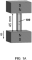
- the MagLev configuration shown in FIG. 1A has a spatial arrangement of magnets in which the sample container (e.g., a square cuvette with a height of, e.g., 45 mm) is sandwiched between two block NdFeB permanent magnets.
- This configuration does not allow the user (i) to easily add or remove the paramagnetic medium or the levitating samples (particularly viscous or sticky samples); (ii) to observe the levitating sample from the top or the bottom; (iii) to move the paramagnetic medium in the container along the central axis between the magnets; and (iv) to accommodate sample containers higher than the distance of separation between the magnets, such as, for example, tall vials and test tubes.
- MagLev systems using cylinder-shaped magnets (e.g., ring magnets). These "axial" MagLev devices enable access to the sample along the central axis of the magnetic field, which is not possible using the block-type magnets of MagLev devices (e.g., the device of FIG. 1A ). In some embodiments, axial MagLev enables simple procedures with which to perform density-based Magneto-Archimedean analyses, separations, and other manipulations.
- density can be used to, for example, (i) separate or analyze different types of non-biological and biological materials (e.g., glass, metals, crystal polymorphs, polymer particles, mammalian cells, yeasts, and bacteria); (ii) monitor chemical processes that accompany changes in density (e.g., chemical reactions on a solid support and polymerization); monitor binding events (e.g., binding of ligands with enzymes, antibodies with antigens, and antibodies with cells); (iii) perform contact-free orientation of objects and self-assembly in three-dimensions; and (iv) perform quality-control of injection-molded plastic parts.
- non-biological and biological materials e.g., glass, metals, crystal polymorphs, polymer particles, mammalian cells, yeasts, and bacteria
- monitor chemical processes that accompany changes in density e.g., chemical reactions on a solid support and polymerization
- monitor binding events e.g., binding of ligands with enzymes, antibodies with antigens, and
- a magnetic levitation system including:
- the first cavity is cylinder-shaped.
- the cross section of the first cavity is in the shape of a triangle, a square or a hexagon, or any other symmetrical shape.
- Applicants have surprisingly found that when a pair of cylinder-shaped magnets (e.g., ring magnets) with like-poles facing (analogous to the anti-Helmholtz configuration using electromagnets), a linear, axially-symmetric magnetic field is achieved, which can be used to levitate diamagnetic and weakly paramagnetic objects (i.e., objects with comparatively weaker paramagnetic properties and a comparatively lower value of magnetic susceptibility; e.g., aluminum) in a paramagnetic medium (e.g., aqueous solutions of MnCl 2 or GdCl 3 ) for density-based analyses, separations, and manipulations ( see, e.g., FIG.
- a paramagnetic medium e.g., aqueous solutions of MnC
- the use of a linear magnetic field between the ring magnets helps streamline the procedures to calibrate and carry out density measurements.
- the nonlinear portion of the magnetic field, particularly the field in the cavity of the ring magnet could also be used to perform density-based separations and manipulations.
- the axial MagLev system is described with reference to FIG. 1B .
- an axial MagLev system 100 is described, including a first cylinder-shaped magnet 101, a second cylinder-shaped magnet 103 coaxially aligned with the first cylinder-shaped magnet 101, and a first cylinder-shaped cavity 105 coaxially aligned with the first cylinder-shaped magnet 101, according to one or more embodiments.
- the first cylinder-shaped cavity 105 spans through the entire height of the first cylinder-shaped magnet 101. In other embodiments, the first cylinder-shaped cavity 105 spans through a portion of the height of the first cylinder-shaped magnet 101.
- the magnetic levitation system 100 includes a second cylinder-shaped cavity 111 coaxially aligned with the second cylinder-shaped magnet 103.
- the second cylinder-shaped cavity 111 spans through the entire height of the second cylinder-shaped magnet 103. In other embodiments, the second cylinder-shaped cavity 111 spans through a portion of the height of the second cylinder-shaped magnet 103.
- the first and second cylinder-shaped magnets 101 and 103 are NdFeB magnets.
- the first and second cavities, 105 and 111, respectively, are cylinder-shaped.
- the cross section of the first and/or second cavities are in the shape of a triangle, a square, a hexagon, or any other symmetrical shape.
- the axial MagLev system according to one or more embodiments disclosed herein (comprising two like-pole-facing cylinder-shaped magnets) results in a linear magnetic field between the first and the second magnets.
- the size of the magnets, aspect ratios of the magnets, and/or the distance between the two magnets are further optimized to yield a linear magnetic field.
- the optimized, linear magnetic field generated between the two ring magnets (coaxially aligned and like-poles facing) enables the levitation of diamagnetic and weakly paramagnetic materials in a paramagnetic suspending medium, and makes density measurements more straightforward.
- a linear magnetic field exists at the space 107 between the first and the second magnets, 101 and 103, respectively.
- the linear magnetic field extends into the first and/or second cylinder-shaped cavities, 105 and 111, respectively.
- the linear magnetic field extends into at least about half the height of the first and/or second cylinder-shaped cavities, 105 and 111, respectively.
- the term "linear magnetic field" as used herein refers to the scenario where the vector of the magnetic field varies linearly along the central axis of the configuration so that the magnetic field has a linear gradient.
- the cylinder-shaped magnet is also referred to as a "ring magnet.”
- the first and second cylinder-shaped magnets have different radii and/or heights. In some embodiments, the first and second cylinder-shaped magnets have the same radius or the same height, or both.
- the axial MagLev system further includes a container (e.g., 109 in FIG. 1B ) configured to hold a paramagnetic medium and at least partially disposed between the first and the second cylinder-shaped magnets.
- the container 109 further includes an inlet 113 configured to allow adding or removing the paramagnetic medium or a paramagnetic or diamagnetic sample.
- the container 109 includes two ends (a top end and a bottom end), and in certain embodiments, at least one of the ends (e.g., the top end of container 109) extends into or through the first cylinder-shaped cavity 105.
- the first cylinder-shaped cavity 105 allows the easy placement of the container 109 between the two facing magnets 101 and 103 and the easy removal of the container 109 from the axial MagLev system 100, both through the first cylinder-shaped cavity 105.
- the other end of the container e.g., the bottom end of container 109 extends into or through the second cylinder-shaped cavity 111 (not shown in FIG. 1B ).
- the second cylinder-shaped cavity 111 allows the easy placement of the container 109 between the two facing magnets 101 and 103 and the easy removal of the container 109 from the axial MagLev system 100, both through the second cylinder-shaped cavity 111.
- the container include a cuvette and a test tube.
- the size and/or aspect ratios of the first and/or second cylinder-shaped magnets are described, which result in a linear magnetic field between the two cylinder-shaped magnets.
- the distance between the surfaces of the like-poles of the first and second cylinder-shaped magnets is d
- the heights of the first and second cylinder-shaped magnets are h 1 and h 2 , respectively
- the ratio of at least one of h 1 and h 2 to d is from about 0.2 : 1 to about 10 : 1.
- the ratio of at least one of h 1 and h 2 to d is about 0.5 : 1, 0.8 : 1, 1: 1, 1.5 : 1, 2 : 1, 3 : 1, 4 : 1, 5 : 1, 6 : 1, 7 : 1, 8 : 1, 9: 1, or 10 : 1, or in a range bounded by any of the two values for the ratio disclosed herein.
- the ratio of h 1 to d or h 2 to d is from about 0.5 : 1 to about 10 : 1, from about 1 : 1 to about 10 : 1, from about 2 : 1 to about 10 : 1, from about 3 : 1 to about 10 : 1, from about 4 : 1 to about 10 : 1, from about 5 : 1 to about 10 : 1, from about 6 : 1 to about 10 : 1, from about 7 : 1 to about 10 : 1, from about 8 : 1 to about 10 : 1, or from about 9 : 1 to about 10 : 1.
- the ratio of h 1 to d or h 2 to d is from about 0.5 : 1 to about 9 : 1, from about 1 : 1 to about 9 : 1, from about 2 : 1 to about 9 : 1, from about 3 : 1 to about 9 : 1, from about 4 : 1 to about 9 : 1, from about 5 : 1 to about 9 : 1, from about 6 : 1 to about 9 : 1, from about 7 : 1 to about 9 : 1, or from about 8 : 1 to about 9 : 1.
- the ratio of h 1 to d or h 2 to d is from about 0.5 : 1 to about 8 : 1, from about 0.75 : 1 to about 8 : 1, from about 2 : 1 to about 8 : 1, from about 3 : 1 to about 8 : 1, from about 4 : 1 to about 8 : 1, from about 5 : 1 to about 8 : 1, from about 6 : 1 to about 8 : 1, or from about 7 : 1 to about 8 : 1.
- the ratio of h 1 to d or h 2 to d is from about 0.5 : 1 to about 4 : 1, from about 0.75 : 1 to about 3 : 1, from about 1 : 1 to about 2 : 1, from about 1.5 : 1 to about 2 : 1, or from about 1.6 : 1 to about 1.8.
- the ratio of at least one of h 1 and h 2 to d is about 1.67 : 1.
- the first cylinder-shaped magnet's inner diameter is id 1
- the ratio of id 1 to d is from about 0.2 : 1 to about 10 : 1.
- the ratio of id 1 to d is from about 0.5 : 1 to about 10 : 1, from about 1 : 1 to about 10 : 1, from about 2 : 1 to about 10 : 1, from about 3 : 1 to about 10 : 1, from about 4 : 1 to about 10 : 1, from about 5 : 1 to about 10 : 1, from about 6 : 1 to about 10 : 1, from about 7 : 1 to about 10 : 1, from about 8 : 1 to about 10 : 1, or from about 9 : 1 to about 10 : 1.
- the ratio of id 1 to d is from about 0.5 : 1 to about 9 : 1, from about 1 : 1 to about 9 : 1, from about 2 : 1 to about 9 : 1, from about 3 : 1 to about 9 : 1, from about 4 : 1 to about 9 : 1, from about 5 : 1 to about 9 : 1, from about 6 : 1 to about 9 : 1, from about 7 : 1 to about 9 : 1, or from about 8 : 1 to about 9 : 1.
- the ratio of id 1 to d is from about 0.5 : 1 to about 8 : 1, from about 0.75 : 1 to about 8 : 1, from about 2 : 1 to about 8 : 1, from about 3 : 1 to about 8 : 1, from about 4 : 1 to about 8 : 1, from about 5 : 1 to about 8 : 1, from about 6 : 1 to about 8 : 1, or from about 7 : 1 to about 8 : 1.
- the ratio of id 1 to d is from about 0.5 : 1 to about 4 : 1, from about 0.75 : 1 to about 3 : 1, from about 1 : 1 to about 2 : 1, from about 1.5 : 1 to about 2 : 1, or from about 1.6 : 1 to about 1.8.
- the ratio of id 1 to d is about 1.67 : 1.
- the first cylinder-shaped magnet's outer diameter is od 1 ; and the ratio of od 1 to d is from about 0.3 : 1 to about 100 : 1.
- the ratio of od 1 to d is from about 0.5 : 1 to about 50 : 1, from about 1 : 1 to about 50 : 1, from about 2 : 1 to about 50 : 1, from about 3 : 1 to about 50 : 1, from about 4 : 1 to about 50 : 1, from about 5 : 1 to about 50 : 1, from about 6 : 1 to about 50 : 1, from about 7 : 1 to about 50 : 1, from about 8 : 1 to about 50 : 1, from about 9 : 1 to about 50 : 1 or from about 10 : 1 to about 50 : 1.
- the ratio of od 1 to d is from about 1 : 1 to about 10 : 1, from about 2 : 1 to about 9 : 1, from about 3 : 1 to about 8 : 1, from about 4 : 1 to about 7 : 1, from about 4 : 1 to about 6 : 1, or from about 4 : 1 to about 5 : 1.
- the ratio of od 1 to d is about 5 : 1.
- the ratio of the first cylinder-shaped magnet's inner diameter (id 1 ) : outer diameter (od 1 ) : height (h 1 ): distance between the surfaces of the like-poles of the first and second cylinder-shaped magnets (d) is about 1-5 : 1-10 : 1-5 : 1. In some embodiments, the ratio of the first cylinder-shaped magnet's inner diameter (id 1 ) : outer diameter (od 1 ) : height (h 1 ): distance between the surfaces of the like-poles of the first and second cylinder-shaped magnets (d) is about 1-3 : 2-8 : 1-3 : 1.
- the ratio of the first cylinder-shaped magnet's inner diameter (id 1 ) : outer diameter (od 1 ) : height (h 1 ): distance between the surfaces of the like-poles of the first and second cylinder-shaped magnets (d) is about 1-2 : 3-6 : 1-2 : 1. In some embodiments, the ratio of the first cylinder-shaped magnet's inner diameter (id 1 ) : outer diameter (od 1 ) : height (h 1 ): distance between the surfaces of the like-poles of the first and second cylinder-shaped magnets (d) is about 1.67 : 5 : 1.67 : 1.
- the second cylinder-shaped magnet's inner diameter is id 2
- the ratio of id 2 to d is from about 0.2 : 1 to about 10 : 1.
- the ratio of id 2 to d is from about 0.5 : 1 to about 10 : 1, from about 1 : 1 to about 10 : 1, from about 2 : 1 to about 10 : 1, from about 3 : 1 to about 10 : 1, from about 4 : 1 to about 10 : 1, from about 5 : 1 to about 10 : 1, from about 6 : 1 to about 10 : 1, from about 7 : 1 to about 10 : 1, from about 8 : 1 to about 10 : 1, or from about 9 : 1 to about 10 : 1.
- the ratio of id 2 to d is from about 0.5 : 1 to about 9 : 1, from about 1 : 1 to about 9 : 1, from about 2 : 1 to about 9 : 1, from about 3 : 1 to about 9 : 1, from about 4 : 1 to about 9 : 1, from about 5 : 1 to about 9 : 1, from about 6 : 1 to about 9 : 1, from about 7 : 1 to about 9 : 1, or from about 8 : 1 to about 9 : 1.
- the ratio of id 2 to d is from about 0.5 : 1 to about 8 : 1, from about 0.75 : 1 to about 8 : 1, from about 2 : 1 to about 8 : 1, from about 3 : 1 to about 8 : 1, from about 4 : 1 to about 8 : 1, from about 5 : 1 to about 8 : 1, from about 6 : 1 to about 8 : 1, or from about 7 : 1 to about 8 : 1.
- the ratio of id 2 to d is from about 0.5 : 1 to about 4 : 1, from about 0.75 : 1 to about 3 : 1, from about 1 : 1 to about 2 : 1, from about 1.5 : 1 to about 2 : 1, or from about 1.6 : 1 to about 1.8.
- the ratio of id 2 to d is about 1.67 : 1.
- the second cylinder-shaped magnet's outer diameter is od 2 ; and the ratio of od 2 to d is from about 0.3 : 1 to about 100 : 1.
- the ratio of od 2 to d is from about 0.5 : 1 to about 50 : 1, from about 1 : 1 to about 50 : 1, from about 2 : 1 to about 50 : 1, from about 3 : 1 to about 50 : 1, from about 4 : 1 to about 50 : 1, from about 5 : 1 to about 50 : 1, from about 6 : 1 to about 50 : 1, from about 7 : 1 to about 50 : 1, from about 8 : 1 to about 50 : 1, from about 9 : 1 to about 50 : 1 or from about 10 : 1 to about 50 : 1.
- the ratio of od 2 to d is from about 1 : 1 to about 10 : 1, from about 2 : 1 to about 9 : 1, from about 3 : 1 to about 8 : 1, from about 4 : 1 to about 7 : 1, from about 4 : 1 to about 6 : 1, or from about 4 : 1 to about 5 : 1.
- the ratio of od 2 to d is about 5 : 1.
- the ratio of the second cylinder-shaped magnet's inner diameter (id 2 ) : outer diameter (od 2 ) : height (h 2 ): distance between the surfaces of the like-poles of the first and second cylinder-shaped magnets (d) is about 1-5 : 1-10 : 1-5 : 1. In some embodiments, the ratio of the second cylinder-shaped magnet's inner diameter (id 2 ) : outer diameter (od 2 ) : height (h 2 ): distance between the surfaces of the like-poles of the first and second cylinder-shaped magnets (d) is about 1-3 : 2-8 : 1-3 : 1.
- the ratio of the second cylinder-shaped magnet's inner diameter (id 2 ) : outer diameter (od 2 ) : height (h 2 ): distance between the surfaces of the like-poles of the first and second cylinder-shaped magnets (d) is about 1-2 : 3-6 : 1-2 : 1. In some embodiments, the ratio of the second cylinder-shaped magnet's inner diameter (id 2 ) : outer diameter (od 2 ) : height (h 2 ): distance between the surfaces of the like-poles of the first and second cylinder-shaped magnets (d) is about 1.67 : 5 : 1.67 : 1.
- the second cylinder-shaped cavity 111 spans through the entire height of the second cylinder-shaped magnet 103 and coaxially aligned with the second cylinder-shaped magnet 103; and the first and/or second cylinder-shaped magnet's inner diameter is from about 15 mm to about 40 mm. In some embodiments, the first or second cylinder-shaped magnet's inner diameter is from about 15 mm to about 40 mm, from about 20 mm to about 30 mm, or from about 22 mm to about 27 mm. In some embodiments, the first and/or second cylinder-shaped magnet's inner diameter is about 25 mm.
- the first and/or second cylinder-shaped magnet's outer diameter is from about 50 mm to about 100 mm. In some embodiments, the first and/or second cylinder-shaped magnet's outer diameter is from about 60 mm to about 90 mm. In some embodiments, the first and/or second cylinder-shaped magnet's outer diameter is from about 70 mm to about 80 mm. In some specific embodiments, the first or second cylinder-shaped magnet's outer diameter is about 75, 76, or 77 mm.
- the first and/or second cylinder-shaped magnet's height is from about 15 mm to about 50 mm, from about 15 mm to about 40 mm, from about 20 mm to about 30 mm, or from about 20 mm to about 25 mm. In some embodiments, the first or second cylinder-shaped magnet's height is about 25 mm.
- the distance between the surfaces of the like-poles of the first and second cylinder-shaped magnets is from about 5 mm to about 50 mm, from about 10 mm to about 50 mm, from about 10 mm to about 40 mm, from about 10 mm to about 30 mm, or from about 10 mm to about 20 mm. In some embodiments, the distance between the surfaces of the like-poles of the first and second cylinder-shaped magnets is about 15 mm.
- the maximal magnetic field along the common axis of the first and second cylinder-shaped magnets is about 0.20-0.50 T.
- the maximum Bo along the central axis between the first and second cylinder-shaped magnets is ⁇ 0.33 T
- the linear magnetic field extends into the cavities of the ring magnets (approximately half of the distance of separation between the magnets).
- the paramagnetic medium includes an aqueous solution of a paramagnetic compound.
- the paramagnetic compound is selected from the group consisting of MnCl 2 , MnBr 2 , CuSO 4 , GdCl 3 , DyCl 3 , HoCl 3 , a Gd chelated compound, and a combination thereof.
- the Gd chelated compound is gadolinium (III) diethylenetriaminepentaacetic acid.
- the paramagnetic medium includes an aqueous solution of MnCl 2 . In some embodiments, the paramagnetic medium includes a hydrophobic paramagnetic medium or a paramagnetic ionic liquid.
- a method of analyzing a diamagnetic or paramagnetic sample including:
- the paramagnetic medium or the diamagnetic or paramagnetic sample is added through the first cylinder-shaped cavity. In some embodiments, the method further includes removing the paramagnetic medium or the diamagnetic or paramagnetic sample. In some embodiments, the paramagnetic medium or the diamagnetic or paramagnetic sample is removed through the first cylinder-shaped cavity.
- the paramagnetic medium includes an aqueous solution of a paramagnetic compound, a hydrophobic paramagnetic medium, or a paramagnetic ionic liquid.
- the paramagnetic compound is selected from the group consisting of MnCl 2 , MnBr 2 , CuSO 4 , GdCl 3 , DyCl 3 , HoCl 3 , a Gd chelated compound, and a combination thereof.
- the Gd chelated compound is gadolinium (III) diethylenetriaminepentaacetic acid.
- the paramagnetic medium includes an aqueous solution of MnCl 2 .
- the paramagnetic medium further includes cetyltrimethylammonium bromide.
- the diamagnetic or paramagnetic includes a crosslinked polymer.
- the method further includes determining the density of the crosslinked polymer. In some embodiments, the method further includes generating a standard curve correlating a sample's levitation height in the system with its density and determining the density of the crosslinked polymer using the standard curve and its levitation height in the system. In some embodiments, the crosslinked polymer comprises PDMS.
- first, second, third, etc. may be used herein to describe various elements, these elements are not to be limited by these terms. These terms are simply used to distinguish one element from another. Thus, a first element, discussed below, could be termed a second element without departing from the teachings of the exemplary embodiments.
- Spatially relative terms such as “above,” “below,” “left,” “right,” “in front,” “behind,” and the like, may be used herein for ease of description to describe the relationship of one element to another element, as illustrated in the figures. It will be understood that the spatially relative terms, as well as the illustrated configurations, are intended to encompass different orientations of the apparatus in use or operation in addition to the orientations described herein and depicted in the figures.
- FIG. 1A exemplifies a MagLev device configuration according to some examples not falling with the literal scope of the claims, comprising two like-poles facing, block magnets (e.g., NdFeB permanent magnets, W ⁇ L ⁇ H: 50.8 mm ⁇ 50.8 mm ⁇ 25.4 mm) positioned coaxially with a distance of separation of 45.0 mm.
- a cuvette e.g., 45 mm in height
- a paramagnetic medium e.g., aqueous solutions of MnCl 2 ).
- an axial MagLev device includes cylinder-shaped magnets, e . g ., ring magnets, which results in a configuration that removes the physical barriers to physical sampling in the magnetic field that are present in the MagLev device of FIG. 1A . Therefore, in some embodiments, axial MagLev simplifies the procedures used to carry out density-based analyses, separations, and manipulations.
- the optimized, linear magnetic field generated between the two ring magnets (coaxially aligned and like-poles facing) enables the levitation of diamagnetic (and weakly paramagnetic; e . g ., aluminum) materials in a paramagnetic suspending medium, and makes density measurements more straightforward.
- the axial configuration enables (i) the addition of samples and/or paramagnetic medium from an open end of the container, and the retrieval of samples from the container while they are levitating in the magnetic field (e.g., a sub-population of a cluster of small particles); (ii) the ability to view the samples 360° around the sample container and from its top and the bottom; and (iii) convenient density measurements of small quantities (as small as a single sub-millimeter particle, as demonstrated) of samples.
- the compact design, portability, affordability, and simplicity in use of the axial MagLev device will broaden the uses of magnetic methods in analyzing, separating, and/or manipulating different types of samples (e.g., solids, liquids, powders, pastes, gels, and biological entities) in areas such as, for example, materials sciences, chemistry, and biochemistry.
- samples e.g., solids, liquids, powders, pastes, gels, and biological entities
- a pair of ring magnets were positioned with like-poles facing (analogous to the anti-Helmholtz configuration using electromagnets) to engineer a linear, axially-symmetric magnetic field, and this field used to levitate diamagnetic and weakly paramagnetic (e.g., aluminum) objects in a paramagnetic medium (e.g., aqueous solutions of MnCl 2 or GdCl 3 ) for density-based analyses, separations, and manipulations ( FIG. 1B ).
- a paramagnetic medium e.g., aqueous solutions of MnCl 2 or GdCl 3
- the use of a linear magnetic field between the ring magnets helps simplify the procedures with which to calibrate and carry out density measurements.
- the nonlinear portion of the magnetic field particularly the field in the cavity of the ring magnet, can also be used to perform density-based separations and manipulations.
- FIG. 1B exemplifies an axial MagLev device, including two like-poles facing ring magnets (e.g., NdFeB permanent magnets, OD ⁇ ID ⁇ H: 76.2 mm ⁇ 25.4 mm ⁇ 25.4 mm) positioned coaxially with a distance of separation of 15.0 mm, according to one or more embodiments.
- a cuvette containing the sample (represented by a 3 mm sphere in FIG. 1B ) is included to show the size of the devices.
- the size and aspect ratios of the magnets were optimized to yield a linear magnetic field.
- the maximum Bo along the central axis between the magnets is about 0.3 T, 0.4 T, 0.5 T, 0.6 T, 0.7 T, 0.8 T, 0.9 T 1.0 T, or in a range bounded by any two values disclosed herein.
- the maximum Bo along the central axis between the magnets is ⁇ 0.33 T, and the linear magnetic field extends into the cavities of the ring magnets (approximately half of the distance of separation between the magnets).
- this geometry made it possible to perform density-based analyses and separations of diamagnetic and weakly paramagnetic samples, and to exchange the paramagnetic medium surrounding the levitating objects (e.g., by moving the sample container relative to the magnets).
- the axial MagLev configuration using two ring magnets makes a number of new procedures either accessible, or more convenient than those for conventional MagLev. Because, in some embodiments, both the top and bottom of the sample container are easily accessible in this axial configuration, it is straightforward to recover samples, and to exchange the paramagnetic medium surrounding the levitating objects, without having to remove the sample container from the magnetic field.
- two ring magnets e.g., NdFeB permanent magnets
- NdFeB permanent magnets e.g., NdFeB permanent magnets
- the magnetic field was simulated using Comsol ® to optimize the geometry of the ring magnets, including the inner diameter (id), the outer diameter (od), the height of the magnets (h), and the distance of separation between the magnets (d), to maximize the strength of the linear magnetic field between them.
- the "homothetic" property of the magnetic field generated by permanent magnet(s) was utilized, i.e., the spatial profile (that is its spatial distribution) of the magnetic field remains unchanged while the magnet(s) physical size increases or decreases.
- the "aspect-ratio" of the magnets i.e., id:od:h:d was thus optimized to maximize the strength of the field (see FIGS. 6A-6F and Table 2 for details). The results of these simulations suggest, in some embodiments, that the strength of the magnetic field between the magnets can be linear for Bo up to about 0.4 T or 0.5 T.
- the entire range of the linear gradient in some embodiments, extends slightly into the cavities of the ring magnets, and is approximately the size of the inner diameter of the ring magnet for the setup shown in FIG. 1B .
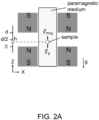
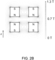
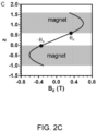
- FIGS. 2A-2C show the design of the axial MagLev device using ring magnets, according to one or more embodiments.
- the z-axis of the setup was anti-aligned with the vector of gravity.
- FIG. 2B shows the spatial profile of the magnetic field on the vertical cross-section through the central axis (the central axis overlaps with the vertical dotted line), according to one or more embodiments.
- FIG. 2C shows the magnetic field strength, Bz, along the vertical dotted line in ( FIG. 2B ), according to one or more embodiments.
- Bo ⁇ 0.33 T for the configuration shown here using two N45-grade NdFeB permanent magnets. The z-axis is unitless for this plot.
- NdFeB ring magnets were used, with the same shape (76 mm in outer diameter, 25 mm in inner diameter, and 25 mm in height) positioned apart by 15 mm.
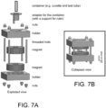
- 3D-printed plastic housing, metal rods, and screws were used to mechanically secure the magnets in space ( FIGS. 7A-7B ).
- rings of different sizes, and also in combination with one or more flux concentrators may also be used to shape the magnetic field, and thus to levitate diamagnetic objects.
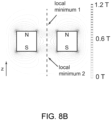
- a single ring magnet with two local minima in its field strength along its central axis was used to levitate diamagnetic objects in a paramagnetic medium, according to one or more examples not falling with the literal scope of the claims. It was found that, in these examples, this spatial profile of the field resulted in nonlinear magnetic field along the central axis on either side, instead of a linear magnetic field as generated in the axial MagLev system disclosed herein (e.g., the axial MagLev system of Figure 1B ). In some examples, an optimized, linear magnetic field simplifies the process by which to calibrate and carry out density measurements.
- the axial MagLev configuration enables (i) facile addition of samples and/or paramagnetic medium from an open end of the container, and retrieval of samples while they levitate in the magnetic field (e.g., a sub-population of a cluster of small particles); (ii) the ability to view the samples 360° around the sample container and from the top and the bottom; and (iii) convenient density measurements of small quantities (as small as a single sub-millimeter particle as demonstrated) of samples.
- an aqueous solution of a paramagnetic species e . g ., MnCl 2 , MnBr 2 , CuSO 4 , GdCl 3 , DyCl 3 , HoCl 3 , and Gd chelates (e.g., gadolinium (III) diethylenetriaminepentaacetic acid) was used to suspend objects.
- these paramagnetic species are inexpensive, transparent in the visible region of the spectrum (even at high concentrations), and commercially available.
- MagLev also works with hydrophobic paramagnetic media and paramagnetic ionic liquids.
- axial MagLev was used to measure the swelling ratios of crosslinked polymer materials, particularly those of irregular shapes and in small quantities, in hydrophobic solvents by measuring the densities of both the dry and fully swollen samples using an aqueous MnCl 2 suspension medium.
- the swelling ratio (the volumetric ratio) of a crosslinked polymer material may characterize its tendency to swell by adsorption of solvents (that is the absorption of a solvent into the crosslinked network of the material). In some embodiments, this ratio reflects, in part, the crosslink density present in the polymeric material and the way in which the solvent interacts with polymeric chains; it is, therefore, a useful parameter in characterizing the crosslinked polymer across different fields, such as solid-phase organic synthesis, development of superabsorbent materials, and use of polymeric materials for drug releasing applications.
- a number of techniques can be used to measure the swelling ratio of crosslinked polymeric materials, including the use of graduated cylinders (to track the bulk volume, e.g., of a collection of particles), gravimetric techniques (to weigh the sample), optical microscopy (to measure the dimension of the sample), and specialized instrumentations.
- graduated cylinders to track the bulk volume, e.g., of a collection of particles
- gravimetric techniques to weigh the sample
- optical microscopy to measure the dimension of the sample
- specialized instrumentations can be tedious, require large quantity of samples (on the scale of grams), and/or have limited compatibility with different types of samples (e.g., irregularly-shaped samples, powders, and delicate or gel-like materials).
- axial MagLev was developed as a simple and broadly compatible tool to measure the swelling ratios of crosslinked polymeric materials in solvents.
- crosslinked PDMS was chosen as a model material for this demonstration. The swelling behavior of PDMS in a variety of organic solvents (in the context of developing PDMS-based microfluidic devices) has been characterized.
- the axial MagLev technique used an aqueous solution of MnCl 2 to levitate samples; the solvents used to swell PDMS samples should not dissolve in the aqueous solutions.
- the solvents characterized in the previous study the following three exemplary hydrophobic solvents are studied here: chloroform, chlorobenzene, and toluene.
- the use of water-miscible solvents can require the same compatibility of solubility of the sample (PDMS soaked with solvents) and the suspension medium ( e.g., using hydrophobic Gd chelate dissolved in hydrophobic solvents).
- hydrophobic organic liquids were used to calibrate the device because: (i) they have known densities; (ii) they can be used as small drops (e.g., 1-2 mm in diameter), a characteristic that facilitates accurate localization of the centroid (in comparison to the ⁇ 4 mm, often irregular-shaped standard glass beads commonly used); and (iii) they are commercially available.
- the solubility of water in the hydrophobic solvents has a negligible influence on the density of the solvents.
- the solubility of water in chlorobenzene is 0.3 mol% at room temperature, and the dissolved water only causes a change in its density of less than 0.01%.
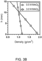
- FIGS. 3A-3B show the calibration of the axial MagLev device using water-insoluble organic liquids, according to one or more embodiments.
- FIG. 3A shows a string of five drops ( ⁇ 3 mL) of organic liquids that were sequentially added to a square cuvette via a pipettor and levitated in an aqueous solution of 0.5 M MnCl 2 , according to one or more embodiments.
- FIG. 3B shows the calibration curves obtained using aqueous MnCl 2 solutions, according to one or more embodiments.
- a ruler with millimeter graduations was placed next to the cuvette (read to ⁇ 0.1 mm), and a digital camera used to take a photo of the drops.
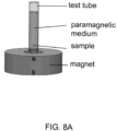
- levitation height h is the distance between the centroid of the drop and the upper surface of the bottom magnet (see FIG. 2A for an illustration of h).
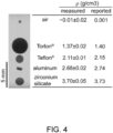
- objects were levitated using a concentrated aqueous solution of 3.0 M DyCl 3 containing 0.01% (v/v) Tween-20, that ranged from a bubble of air ( ⁇ ⁇ 0 g/cm 3 ) to zirconium silicate ( ⁇ ⁇ 3.7 g/cm 3 ).
- all samples were spherical except for the aluminum sample, which was irregular in shape (cut from a sheet of foil, 250 mm thickness).
- the axial MagLev system as disclosed herein demonstrated a range of densities that was expanded beyond that of conventional MagLev, was experimentally much more convenient, and avoided some of the potential problems of tilted MagLev (e.g., the samples rest on the walls of the sample container.)
- the axial MagLev configuration conveniently enables addition and/or retrieval of samples from the container.
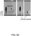
- FIGS. 5A-5C demonstrate these procedures, according to one or more embodiments, by levitating "sticky" or viscous samples (a drop of PDMS prepolymer and a plug of Vaseline ® gel)-the type of samples that are inconveniently measured using the conventional or tilted MagLev devices as the samples tend to stick to the walls of the container, and also to the liquid-air interface.
- the axial MagLev configuration according to one or more embodiments also readily enables retrieval of a targeted fraction of a sample (e.g., from a collection of particles).
- a test tube filled with a paramagnetic medium was placed in the axial MagLev device, and the "sticky" samples added to the container from its top.
- the sample entered the medium by gravity, and levitated in it (nearly instantaneously for mm sized samples, FIGS. 5A-5C ).
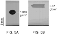
- FIGS. 5A-5B show procedures to add or retrieve samples, according to one or more embodiments.
- FIG. 5A shows a drop of liquid PDMS prepolymer (doped with black graphite powder for visualization) levitated in an aqueous solution of 0.5 M MnCl 2 , according to one or more embodiments. In some embodiments, the drop appeared elliptical due to the visual distortion by the curved wall of the cylindrical test tube.
- FIG. 5B shows a plug of Vaseline ® gel extruded from a syringe levitated in an aqueous solution of 3.0 M MnCl 2 containing 0.1% (v/v) Tween-20, according to one or more embodiments.
- FIG. 5A shows a drop of liquid PDMS prepolymer (doped with black graphite powder for visualization) levitated in an aqueous solution of 0.5 M MnCl 2 , according to one or more embodiments. In some embodiments, the drop appeared elli
- the suspension solution contained 0.5 M MnCl 2 , 1.4 M NaCl (a diamagnetic co-solute used to match the densities of the particles and the solution), and 0.1% (v/v) Tween-20.
- arrows indicate the spread in density of the particles (unit: g/cm 3 ) according to one or more embodiments.
- retrieving a sample from the container placed in the MagLev device is straightforward due to its axial configuration.
- Density standards polyethylene particles, ⁇ 200 ⁇ m in diameter and 1.13 g/cm 3 in nominal density
- a glass Pasteur pipette with its tip bent ⁇ 90° was inserted from the top of the sample container (a test tube with a diameter of ⁇ 25 mm), and a sub-population of particles that levitated in an aqueous MnCl 2 solution were removed.
- the rest of the sample remained levitated and undisturbed.
- Axial MagLev as disclosed herein thus, in certain embodiments, provides a straightforward method to prepare high-quality density standards.
- PDMS was chosen as a model crosslinked polymer to demonstrate the use of axial MagLev in characterizing the swelling behavior of crosslinked polymers in solvents.
- a small piece of PDMS (1.5 mm in diameter and ⁇ 1 mm in thickness, which was prepared by a 1.5 mm biopsy punch) was immersed in solvent for 24 hours.
- the sample was blotted dry and added to the MagLev device for density measurement using an 1.5 M aqueous solution of MnCl 2 containing 0.1% (v/v) cetyltrimethylammonium bromide (a surfactant to help remove air bubbles).
- MagLev enables direct measurement of the density of the sample, irrespective of its volume (or shape).
- the measured densities were converted to the volumetric swelling ratio (see Table 1) using Equation 1.
- V sp is the volume of the swollen sample
- V p is the volume of the dry sample
- ⁇ p is the density of the sample
- ⁇ sp is the density of the swollen sample
- ⁇ s is the density of the solvent
- the diameters of the dry and swollen samples from the same images were measured using the levitation heights, and the swelling ratio estimated.
- the agreement of the results validates the performance of the MagLev technique.
- the divergence from literature values may have originated from different sample preparations.
- this demonstration also highlights the simplicity and compatibility of the MagLev technique in measuring small quantities of samples without requiring more sophisticated tools (e.g., microscopes). Table 1. Swelling ratios of PDMS samples in certain solvents.
- volumetric Swelling Ratio ( f ) Solvent MagLev a Imaging
- Literature c Chloroform 2.1 1.9 2.7 Chlorobenzene 2.2 2.1 1.8 Toluene 2.2 2.2 2.2 a.
- N 3; average of 3 measurements.
- axial MagLev exploits the axially symmetric magnetic field generated by two like-poles facing ring magnets to carry out density-based analyses, separations, and manipulations.
- this configuration of MagLev removes the physical barriers along the central axis of conventional MagLev devices in which sample containers (e.g., square cuvette or capillary tube) are physically sandwiched between two block magnets.
- axial MagLev has four useful characteristics: (i) It provides ready access to the levitating sample and the paramagnetic medium, making it straightforward to add or remove the sample or the suspending medium: (ii) It maintains full clearance (360°) around the sample container by which to view the levitating samples, and also provides ready access to view the samples from both the top and the bottom. (iii) It does not impose a limitation on the height of the sample container, and is broadly compatible with different types of containers (e.g. , cuvettes, vials, test tubes, graduated cylinders, etc.) so long they fit within the inner diameter of the ring magnets. (iv) It concentrates small and/or dilute particles along a common vertical axis, and aids in their visualization and manipulations.
- axial MagLev generates a linear magnetic field between the magnets.
- non-linear magnetic fields could also be used to carry out density-based measurements and separation, provided appropriate calibrations.
- the working distance between the two magnets can be extended at least to ⁇ 38 mm, while the monotonically changing the magnetic field gradient (and thus the density).
- FIGS. 6A-F show the selection of the geometry and the distance of separation between the ring magnets using Comsol ® simulation, according to one or more embodiments.
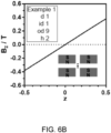
- FIG. 6A is a schematic showing the four independent physical parameters used to define the configuration of the setup (od: out diameter, id: inner diameter, h: height of the magnet, d: distance of separation), according to one or more embodiments. Combinations of the parameters explored using Comsol ® simulation in these embodiments are given in Table 2.
- FIG. 6B shows a specific example of a linear gradient with a max field strength of ⁇ 0.4 T along the central axis between the magnets (dotted line in the inset), according to one or more examples not falling with the literal scope of the claims.
- FIG. 6A is a schematic showing the four independent physical parameters used to define the configuration of the setup (od: out diameter, id: inner diameter, h: height of the magnet, d: distance of separation), according to one or more embodiments. Combinations of the parameters explored using Comsol ®
- FIG. 6C shows a non-linear gradient with a max field strength of ⁇ 0.5 T along the central axis between the magnets (dotted line in the inset), according to one or more examples not falling with the literal scope of the claims.
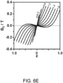
- FIG. 6D shows fine-tuning of the separation distance between the two magnets (od: 3, id: 1, h: 1), according to one or more embodiments.
- FIG. 6E shows the field strength, Bz, along the central axis between the two magnets as the distance of separation was varied from 0.2 to 2 at a step of 0.2, according to one or more embodiments.
- Density is a universal property of all matter, and a simple, inexpensive, and useful MagLev device, such as the axial MagLev device described herein, may expand the utility of MagLev-based density analysis in chemistry, biochemistry, and materials science.
- the compact design, portability, affordability, and simplicity of use of the axial MagLev device may enable characterization of materials (e.g., the swelling behavior of crosslinked polymeric materials in solvents), separations of samples (particularly small quantities, such as, e.g., crystals), and in manipulating samples (e.g., hard, soft, and sticky objects, such as, e.g., gels) without physical contact.
- Table 2 Parameters examined using Comsol ® simulations.
- polyamide-imides Teflon ®
- polytetrafluoroethylene Teflon ®
- aluminum foil was obtained from Sigma-Aldrich.
- zirconium silicate was obtained from Cospheric LLC.
- the density of air was obtained from the CRC Handbook of Chemistry and Physics, 98th Editi on.
- Equation S1 gives the density of a crosslinked polymeric sample in the dry state
- Equation S2 gives the density in the swollen state
- Equations S1-3 m p is the mass of the sample, m s is the mass of the solvent present in the swollen sample, V sp is the volume of the swollen sample, V p is the volume of the dry sample, ⁇ p is the density of the sample, ⁇ sp is the density of the swollen sample, and ⁇ s is the density of the solvent.
- Equation S5 which describes the relationship between the swelling ratio and the densities.
Landscapes
- Physics & Mathematics (AREA)
- Engineering & Computer Science (AREA)
- Electromagnetism (AREA)
- Power Engineering (AREA)
- Chemical & Material Sciences (AREA)
- General Physics & Mathematics (AREA)
- Biochemistry (AREA)
- Pathology (AREA)
- Health & Medical Sciences (AREA)
- Analytical Chemistry (AREA)
- Life Sciences & Earth Sciences (AREA)
- General Health & Medical Sciences (AREA)
- Immunology (AREA)
- Condensed Matter Physics & Semiconductors (AREA)
- Combustion & Propulsion (AREA)
- Investigating Or Analyzing Materials By The Use Of Magnetic Means (AREA)
- Investigating Or Analysing Biological Materials (AREA)
- Apparatus Associated With Microorganisms And Enzymes (AREA)
- Hard Magnetic Materials (AREA)
- Magnetic Resonance Imaging Apparatus (AREA)
Claims (29)
- Magnetschwebetechnik-System (100) zum Schweben lassen einer diamagnetischen oder paramagnetischen Probe, wobei das System umfasst:einen ersten zylinderförmigen Magneten (101);einen zweiten zylinderförmigen Magneten (103), der koaxial mit dem ersten zylinderförmigen Magneten (101) ausgerichtet ist;einen ersten Hohlraum (105), der koaxial mit dem ersten zylinderförmigen Magneten (101) ausgerichtet und in diesem ausgebildet ist; undeinen Behälter (109), der dazu konfiguriert ist, ein paramagnetisches Medium aufzunehmen;wobei eine Oberfläche des ersten zylinderförmigen Magneten (101) eine Polarität aufweist und parallel zu einer Oberfläche des zweiten zylinderförmigen (103) Magneten ist, der die gleiche Polarität aufweist, und dieser zugewandt ist, um zu bewirken, dass die Bz-Komponente des Magnetfelds linear entlang der Mittelachse zwischen dem ersten und zweiten zylinderförmigen Magneten variiert.
- System (100) nach Anspruch 1, wobei der erste Hohlraum (105) zylinderförmig ist; oder wobei sich der erste Hohlraum (105) über die gesamte Höhe des ersten zylinderförmigen Magneten (101) erstreckt; und/oder
wobei sich das lineare Magnetfeld in den ersten Hohlraum (105) hinein erstreckt. - System (100) nach einem der vorhergehenden Ansprüche, wobei der erste und zweite zylinderförmige Magnet einen unterschiedlichen Radius oder eine unterschiedliche Höhe aufweisen, oder
wobei der erste und zweite zylinderförmige Magnet den gleichen Radius, die gleiche Höhe oder beides aufweisen. - System (100) nach einem der vorhergehenden Ansprüche, wobei das System ferner einen zweiten Hohlraum (111) umfasst, der in dem zweiten zylinderförmigen Magneten (103) ausgebildet und koaxial mit diesem ausgerichtet ist, optional:
wobei der zweite Hohlraum (111) zylinderförmig ist. - System (100) nach einem der vorhergehenden Ansprüche, wobei der Abstand zwischen den Oberflächen der gleichnamigen Pole des ersten und zweiten zylinderförmigen Magneten d ist und die Höhen des ersten und zweiten zylinderförmigen Magneten h1 und h2 sind; und das Verhältnis von mindestens einer von h1 und h2 zu d etwa 0,2:1 bis etwa 10:1 beträgt, optional wobei das Verhältnis von mindestens einer von h1 und h2 zu d etwa 1,67:1 beträgt.
- System (100) nach einem der vorhergehenden Ansprüche, wobei der Innendurchmesser des ersten zylinderförmigen Magneten (101) id1 ist; und das Verhältnis von id1 zu d etwa 0,2:1 bis etwa 10:1 beträgt, optional wobei das Verhältnis von id1 zu d etwa 1,67:1 beträgt.
- System (100) nach einem der vorhergehenden Ansprüche, wobei der Außendurchmesser des ersten zylinderförmigen Magneten (101) od1 ist; und das Verhältnis von od1 zu d etwa 0,3:1 bis etwa 100:1 beträgt, optional wobei das Verhältnis von od1 zu d etwa 5:1 beträgt.
- System (100) nach einem der vorhergehenden Ansprüche, wobei das System ferner einen zweiten zylinderförmigen (111) Hohlraum umfasst, der in dem zweiten zylinderförmigen Magneten (103) ausgebildet und koaxial mit diesem ausgerichtet ist;der Innendurchmesser des zweiten zylinderförmigen Magneten (103) id2 ist; unddas Verhältnis von id2 zu d etwa 0,2:1 bis etwa 10:1 beträgt, optional wobei das Verhältnis von id2 zu d etwa 1,67:1 beträgt.
- System (100) nach einem der vorhergehenden Ansprüche, wobei das System ferner einen zweiten Hohlraum (111) umfasst, der in dem zweiten zylinderförmigen Magneten (103) ausgebildet und koaxial mit diesem ausgerichtet ist;der Außendurchmesser des zweiten zylinderförmigen Magneten od2 ist; unddas Verhältnis von od2 zu d etwa 0,3:1 bis etwa 100:1 beträgt, optional wobei das Verhältnis von od2 zu d etwa 5:1 beträgt.
- System (100) nach einem der vorhergehenden Ansprüche, wobei der erste Hohlraum (105) zylinderförmig ist und das Verhältnis von Innendurchmesser (id1):Außendurchmesser (od1):Höhe (h1) des ersten zylinderförmigen Magneten (101):Abstand zwischen den Oberflächen der gleichnamigen Pole des ersten und zweiten zylinderförmigen Magneten (d) etwa 1,67:5:1,67:1 beträgt; und/oder wobei:das System (100) ferner einen zweiten zylinderförmigen Hohlraum (111) umfasst, der in dem zweiten zylinderförmigen Magneten (103) ausgebildet und koaxial mit diesem ausgerichtet ist; unddas Verhältnis von Innendurchmesser (id2):Außendurchmesser (od2):Höhe (h2) des zweiten zylinderförmigen Magneten: Abstand zwischen den Oberflächen der gleichnamigen Pole des ersten und zweiten zylinderförmigen Magneten (d) etwa 1,67:5:1,67:1 beträgt.
- System (100) nach einem der vorhergehenden Ansprüche, wobei der Behälter (109) mindestens teilweise zwischen dem ersten und dem zweiten zylinderförmigen Magneten angeordnet ist; optional
wobei der Behälter (109) ferner einen Einlass umfasst, der dazu konfiguriert ist, das Hinzufügen oder Entfernen des paramagnetischen Mediums oder einer paramagnetischen oder diamagnetischen Probe zu ermöglichen. - System (100) nach einem der Ansprüche 1 bis 10, wobei der Behälter (109) mindestens teilweise zwischen dem ersten und dem zweiten zylinderförmigen Magneten angeordnet ist, wobei (109) der Behälter zwei Enden umfasst, von denen sich mindestens eines in den ersten Hohlraum hinein oder durch diesen hindurch erstreckt; und optionalwobei das System ferner einen zweiten Hohlraum (111) umfasst, der in dem zweiten zylinderförmigen (103) Magneten ausgebildet und koaxial mit diesem ausgerichtet ist; undsich das andere Ende der zwei Enden des Behälters in den zweiten zylinderförmigen Hohlraum (111) hinein oder durch diesen hindurch erstreckt.
- System (100) nach Anspruch 11 oder Anspruch 12, wobei der Behälter (109) eine Küvette ist; und/oder
wobei das paramagnetische Medium eine wässrige Lösung einer paramagnetischen Verbindung umfasst. - System (100) nach Anspruch 13, wobei die paramagnetische Verbindung aus der Gruppe bestehend aus MnCl2, MnBr2, CuSO4, GdCl3, DyCl3, HoCl3, einer Gd-chelatierten Verbindung und einer Kombination davon ausgewählt ist; optional
wobei die Gd-chelatierte Verbindung Gadolinium(III)-Diethylentriaminpentaessigsäure ist. - System (100) nach Anspruch 11 oder Anspruch 13, wobei das paramagnetische Medium eine wässrige MnCl2-Lösung umfasst.
- System (100) nach Anspruch 11, wobei das paramagnetische Medium ein hydrophobes paramagnetisches Medium oder eine paramagnetische ionische Flüssigkeit umfasst.
- System (100) nach einem der vorhergehenden Ansprüche, wobei das maximale Magnetfeld entlang der gemeinsamen Achse des ersten und zweiten zylinderförmigen Magneten etwa 0,20-0,50 T beträgt; und/oder
wobei der erste und zweite zylinderförmige Magnet NdFeB-Magnete sind. - System (100) nach einem der vorhergehenden Ansprüche, wobei das System optional einen zweiten zylinderförmigen Hohlraum (111) umfasst, der sich über die gesamte Höhe des zweiten zylinderförmigen Magneten (103) erstreckt und koaxial mit dem zweiten zylinderförmigen Magneten ausgerichtet ist; und der Innendurchmesser des ersten oder zweiten zylinderförmigen Magneten etwa 15 mm bis etwa 40 mm beträgt, optional wobei der Innendurchmesser des ersten oder zweiten zylinderförmigen Magneten etwa 25 mm beträgt.
- System (100) nach einem der vorhergehenden Ansprüche, wobei das System optional einen zweiten zylinderförmigen Hohlraum (111) umfasst, der sich über die gesamte Höhe des zweiten zylinderförmigen Magneten (103) erstreckt und koaxial mit dem zweiten zylinderförmigen Magneten ausgerichtet ist; und der Außendurchmesser des ersten oder zweiten zylinderförmigen Magneten etwa 50 mm bis etwa 100 mm beträgt, optional wobei der Außendurchmesser des ersten oder zweiten zylinderförmigen Magneten etwa 76 mm beträgt.
- System (100) nach einem der vorhergehenden Ansprüche, wobei die Höhe des ersten oder zweiten zylinderförmigen Magneten etwa 15 mm bis etwa 50 mm beträgt, optional wobei die Höhe des ersten oder zweiten zylinderförmigen Magneten etwa 25 mm beträgt.
- System (100) nach einem der vorhergehenden Ansprüche, wobei der Abstand zwischen den Oberflächen der gleichnamigen Pole des ersten und zweiten zylinderförmigen Magneten etwa 5 mm bis etwa 50 mm beträgt, optional wobei der Abstand zwischen den Oberflächen der gleichnamigen Pole des ersten und zweiten zylinderförmigen Magneten etwa 15 mm beträgt.
- Verfahren zum Analysieren einer diamagnetischen oder paramagnetischen Probe, umfassend: Bereitstellen des Systems (100) nach einem der vorhergehenden Ansprüche;Anordnen eines Behälters (109), der dazu konfiguriert ist, ein paramagnetisches Medium zwischen dem ersten und dem zweiten zylinderförmigen Magneten aufzunehmen;Hinzufügen eines paramagnetischen Mediums und einer diamagnetischen oder paramagnetischen Probe, entweder getrennt oder zusammen, in den Behälter (109); undErmöglichen, dass die diamagnetische oder paramagnetische Probe unter dem linearen Magnetfeld zwischen dem ersten und zweiten zylinderförmigen Magneten schwebt.
- Verfahren nach Anspruch 22, wobei das paramagnetische Medium oder die diamagnetische oder paramagnetische Probe durch den ersten zylinderförmigen Hohlraum (105) hinzugefügt wird.
- Verfahren nach Anspruch 23, wobei das Verfahren ferner das Entfernen des paramagnetischen Mediums oder der diamagnetischen oder paramagnetischen Probe umfasst, optional wobei das paramagnetische Medium oder die diamagnetische oder paramagnetische Probe durch den ersten zylinderförmigen Hohlraum (105) hindurch entfernt wird.
- Verfahren nach einem der Ansprüche 22-24, wobei das paramagnetische Medium eine wässrige Lösung einer paramagnetischen Verbindung, ein hydrophobes paramagnetisches Medium oder eine paramagnetische ionische Flüssigkeit umfasst.
- Verfahren nach Anspruch 25, wobei die paramagnetische Verbindung aus der Gruppe bestehend aus MnCl2, MnBr2, CuSO4, GdCl3, DyCl3, HoCl3, einer Gd-chelatierten Verbindung und einer Kombination davon ausgewählt ist, optional wobei die Gd-chelatierte Verbindung Gadolinium(III)-Diethylentriaminpentaessigsäure ist.
- Verfahren nach einem der Ansprüche 22-26, wobei das paramagnetische Medium eine wässrige MnCl2-Lösung umfasst; und oder
wobei das paramagnetische Medium ferner Cetyltrimethylammoniumbromid umfasst. - Verfahren nach einem der Ansprüche 22-27, wobei die diamagnetische oder paramagnetische Probe ein vernetztes Polymer umfasst, optional wobei das Verfahren ferner das Bestimmen der Dichte des vernetzten Polymers umfasst.
- Verfahren nach Anspruch 28, wobei das Verfahren ferner das Erzeugen einer Standardkurve, die die Schwebehöhe einer Probe im System mit ihrer Dichte korreliert, und das Bestimmen der Dichte des vernetzten Polymers unter Verwendung der Standardkurve und seiner Schwebehöhe im System umfasst; und optional
wobei das vernetzte Polymer Polydimethylsiloxan umfasst.
Applications Claiming Priority (3)
| Application Number | Priority Date | Filing Date | Title |
|---|---|---|---|
| US201862738758P | 2018-09-28 | 2018-09-28 | |
| US201962800796P | 2019-02-04 | 2019-02-04 | |
| PCT/US2019/053094 WO2020069081A1 (en) | 2018-09-28 | 2019-09-26 | Magnetic levitation |
Publications (4)
| Publication Number | Publication Date |
|---|---|
| EP3857574A1 EP3857574A1 (de) | 2021-08-04 |
| EP3857574A4 EP3857574A4 (de) | 2022-06-29 |
| EP3857574C0 EP3857574C0 (de) | 2025-04-02 |
| EP3857574B1 true EP3857574B1 (de) | 2025-04-02 |
Family
ID=69953344
Family Applications (1)
| Application Number | Title | Priority Date | Filing Date |
|---|---|---|---|
| EP19864487.4A Active EP3857574B1 (de) | 2018-09-28 | 2019-09-26 | Magnetschwebetechnik |
Country Status (7)
| Country | Link |
|---|---|
| US (1) | US11676750B2 (de) |
| EP (1) | EP3857574B1 (de) |
| JP (1) | JP7612570B2 (de) |
| CN (1) | CN112889121B (de) |
| AU (2) | AU2019347864B2 (de) |
| SG (1) | SG11202102967PA (de) |
| WO (1) | WO2020069081A1 (de) |
Families Citing this family (4)
| Publication number | Priority date | Publication date | Assignee | Title |
|---|---|---|---|---|
| US12427532B2 (en) * | 2019-03-15 | 2025-09-30 | President And Fellows Of Harvard College | Magnetic levitation system |
| US11550362B2 (en) * | 2021-03-31 | 2023-01-10 | Microsoft Technology Licensing, Llc | Rotatably coupled touch screen displays |
| CN115458273B (zh) * | 2022-11-09 | 2023-05-02 | 之江实验室 | 一种双层圆柱型永磁体抗磁悬浮装置及其制备和应用方法 |
| WO2024213807A1 (es) * | 2023-04-11 | 2024-10-17 | Jorge Cervello Vivo | Dispositivo de levitación magnética |
Family Cites Families (23)
| Publication number | Priority date | Publication date | Assignee | Title |
|---|---|---|---|---|
| US4427960A (en) * | 1982-12-06 | 1984-01-24 | Wuerfel Robert P | Magnetic holder for small articles |
| JP2002148104A (ja) | 2000-11-09 | 2002-05-22 | Na:Kk | 磁界発生装置及び液面計 |
| US7859157B2 (en) | 2005-12-08 | 2010-12-28 | Eth Zurich | Magnetic levitation system |
| US20070246430A1 (en) | 2006-04-20 | 2007-10-25 | Chau Yiu C | Fluid Magnetic Treatment Unit having Moving or Stationary Magnets |
| WO2009006409A2 (en) * | 2007-06-29 | 2009-01-08 | President And Fellows Of Harvard College | Density-based methods for separation of materials, monitoring of solid supported reactions and measuring densities of small liquid volumes and solids |
| DE102009015231A1 (de) | 2009-04-01 | 2010-10-07 | Focke & Co.(Gmbh & Co. Kg) | (Leim-)Ventil |
| CN101882903B (zh) * | 2009-05-07 | 2014-12-17 | 洪证南 | 旋转磁悬浮装置及陀螺磁悬浮方法 |
| US8264309B2 (en) * | 2009-09-02 | 2012-09-11 | General Equipment And Manufacturing Company, Inc. | Adjustable magnetic target |
| JP5937019B2 (ja) * | 2010-03-12 | 2016-06-22 | ザ ボード オブ トラスティーズ オブ ザ レランド スタンフォード ジュニア ユニバーシティー | 磁気センサに基づく結合反応速度の定量的な分析 |
| WO2012024691A1 (en) * | 2010-08-20 | 2012-02-23 | President And Fellows Of Harvard College | Multiphase systems for analysis of solid materials |
| WO2012075009A1 (en) | 2010-11-29 | 2012-06-07 | President And Fellows Of Harvard College | Quality control of diamagnetic materials using magnetic levitation |
| WO2012088119A2 (en) * | 2010-12-20 | 2012-06-28 | President And Fellows Of Harvard College | Three dimensional assembly of diamagnetic materials using magnetic levitation |
| CN202649073U (zh) * | 2012-05-25 | 2013-01-02 | 东北大学 | 一种基于电磁悬浮的密度测量装置 |
| US20150135829A1 (en) | 2012-06-14 | 2015-05-21 | Presidents And Fellows Of Harvard College | Levitation of Materials in Paramagnetic Ionic Liquids |
| US20140099253A1 (en) * | 2012-10-05 | 2014-04-10 | Peter A. Kulish | Method and apparatus for magnetic treament of fuel and fluids for combustiion efficiency and reduction of carbon emissions |
| US20150037128A1 (en) * | 2013-08-04 | 2015-02-05 | Gerald Küstler | Monolithic magnets with magnetic field domains for diamagnetic levitation |
| US9482643B2 (en) * | 2013-11-26 | 2016-11-01 | Aspect Imaging Ltd. | Means and methods using paramagnetic agents for in vitro diagnostic applications |
| KR102360036B1 (ko) * | 2014-02-26 | 2022-02-07 | 브리검앤드위민즈하스피탈, 인코포레이티드 | 세포 레비테이션 및 모니터링을 위한 시스템 및 방법 |
| US11114956B2 (en) * | 2015-08-28 | 2021-09-07 | Singapore University Of Technology And Design | Magnetic levitator |
| DE102015116767B4 (de) * | 2015-10-02 | 2020-06-18 | Rubotherm GmbH | Lager, insbesondere für eine Magnetschwebeanordnung |
| GB201518430D0 (en) * | 2015-10-19 | 2015-12-02 | Giamag Technologies As | Magnet apparatus for generating high gradient magnetic field |
| CN105548343B (zh) * | 2015-12-10 | 2018-12-25 | 浙江大学 | 基于磁悬浮的零件缺陷的检测方法 |
| CN107677567A (zh) | 2017-09-29 | 2018-02-09 | 南京工业大学 | 一种基于物质普遍抗磁性的磁漂浮密度分离测量方法 |
-
2019
- 2019-09-26 JP JP2021517196A patent/JP7612570B2/ja active Active
- 2019-09-26 CN CN201980069685.6A patent/CN112889121B/zh active Active
- 2019-09-26 SG SG11202102967PA patent/SG11202102967PA/en unknown
- 2019-09-26 WO PCT/US2019/053094 patent/WO2020069081A1/en not_active Ceased
- 2019-09-26 US US17/279,419 patent/US11676750B2/en active Active
- 2019-09-26 AU AU2019347864A patent/AU2019347864B2/en active Active
- 2019-09-26 EP EP19864487.4A patent/EP3857574B1/de active Active
-
2025
- 2025-08-22 AU AU2025220847A patent/AU2025220847A1/en active Pending
Also Published As
| Publication number | Publication date |
|---|---|
| AU2019347864A1 (en) | 2021-04-29 |
| EP3857574A4 (de) | 2022-06-29 |
| CN112889121A (zh) | 2021-06-01 |
| US11676750B2 (en) | 2023-06-13 |
| EP3857574C0 (de) | 2025-04-02 |
| JP7612570B2 (ja) | 2025-01-14 |
| CN112889121B (zh) | 2023-08-18 |
| EP3857574A1 (de) | 2021-08-04 |
| SG11202102967PA (en) | 2021-04-29 |
| US20220013268A1 (en) | 2022-01-13 |
| AU2019347864B2 (en) | 2025-05-22 |
| AU2025220847A1 (en) | 2025-09-11 |
| WO2020069081A1 (en) | 2020-04-02 |
| JP2022502643A (ja) | 2022-01-11 |
Similar Documents
| Publication | Publication Date | Title |
|---|---|---|
| EP3857574B1 (de) | Magnetschwebetechnik | |
| Ge et al. | “Axial” magnetic levitation using ring magnets enables simple density-based analysis, separation, and manipulation | |
| Xie et al. | An accurate and versatile density measurement device: Magnetic levitation | |
| EP2167216B1 (de) | Materialtrennungsverfahren auf dichtebasis, überwachung feststoffunterstützter reaktionen und messung der dichte kleiner flüssigkeitsvolumina und feststoffe | |
| Nemiroski et al. | Tilted magnetic levitation enables measurement of the complete range of densities of materials with low magnetic permeability | |
| Ge et al. | High-throughput density measurement using magnetic levitation | |
| Dabbagh et al. | Biomedical applications of magnetic levitation | |
| Mirica et al. | Magnetic levitation in the analysis of foods and water | |
| Nemiroski et al. | High-sensitivity measurement of density by magnetic levitation | |
| US20150135829A1 (en) | Levitation of Materials in Paramagnetic Ionic Liquids | |
| EP2732878B1 (de) | Magnetisches Regalsystem und Verfahren zur Verwendung eines magnetischen Regalsystems | |
| Reddy et al. | Determination of the magnetic susceptibility of labeled particles by video imaging | |
| Zhao et al. | Super‐resolution imaging of highly curved membrane structures in giant vesicles encapsulating molecular condensates | |
| Ashkarran et al. | Magnetically levitated plasma proteins | |
| Rodrigues et al. | Magnetophoretic sprinting: A study on the magnetic properties of aqueous lanthanide solutions | |
| Anil-Inevi et al. | Ring magnet-guided magnetic manipulation for biofabrication of 3D cellular structures | |
| Lőrincz et al. | Visualization of displacement fields in a sheared granular system | |
| Lettinga et al. | Rotational diffusion of tracer spheres in packings and dispersions of colloidal spheres studied with time-resolved phosphorescence anisotropy | |
| JP3513591B2 (ja) | 磁気勾配下液中微粒子磁気トラップ分離方法及び装置 | |
| TWI640624B (zh) | 細胞觀測裝置及使用其之細胞收集方法 | |
| WO2019222582A1 (en) | Sample analysis with mirrors | |
| CN107560975B (zh) | 一种用于检测密度的水平方向磁悬浮检测方法 | |
| EP4481364A1 (de) | Verfahren und vorrichtung zur messung der kapazität von adsorptionsmitteln zur absorption von in einem flüssigen medium gelösten substanzen | |
| KR20240001205U (ko) | 자성 분리장치 | |
| Liu et al. | T-Cell Receptor Signaling |
Legal Events
| Date | Code | Title | Description |
|---|---|---|---|
| STAA | Information on the status of an ep patent application or granted ep patent |
Free format text: STATUS: THE INTERNATIONAL PUBLICATION HAS BEEN MADE |
|
| PUAI | Public reference made under article 153(3) epc to a published international application that has entered the european phase |
Free format text: ORIGINAL CODE: 0009012 |
|
| STAA | Information on the status of an ep patent application or granted ep patent |
Free format text: STATUS: REQUEST FOR EXAMINATION WAS MADE |
|
| 17P | Request for examination filed |
Effective date: 20210414 |
|
| AK | Designated contracting states |
Kind code of ref document: A1 Designated state(s): AL AT BE BG CH CY CZ DE DK EE ES FI FR GB GR HR HU IE IS IT LI LT LU LV MC MK MT NL NO PL PT RO RS SE SI SK SM TR |
|
| DAV | Request for validation of the european patent (deleted) | ||
| DAX | Request for extension of the european patent (deleted) | ||
| A4 | Supplementary search report drawn up and despatched |
Effective date: 20220601 |
|
| RIC1 | Information provided on ipc code assigned before grant |
Ipc: G01R 33/12 20060101ALI20220525BHEP Ipc: H01F 7/02 20060101AFI20220525BHEP |
|
| GRAP | Despatch of communication of intention to grant a patent |
Free format text: ORIGINAL CODE: EPIDOSNIGR1 |
|
| STAA | Information on the status of an ep patent application or granted ep patent |
Free format text: STATUS: GRANT OF PATENT IS INTENDED |
|
| INTG | Intention to grant announced |
Effective date: 20241028 |
|
| RIN1 | Information on inventor provided before grant (corrected) |
Inventor name: WHITESIDES, GEORGE M. Inventor name: GE, SHENCHENG |
|
| GRAS | Grant fee paid |
Free format text: ORIGINAL CODE: EPIDOSNIGR3 |
|
| GRAA | (expected) grant |
Free format text: ORIGINAL CODE: 0009210 |
|
| STAA | Information on the status of an ep patent application or granted ep patent |
Free format text: STATUS: THE PATENT HAS BEEN GRANTED |
|
| AK | Designated contracting states |
Kind code of ref document: B1 Designated state(s): AL AT BE BG CH CY CZ DE DK EE ES FI FR GB GR HR HU IE IS IT LI LT LU LV MC MK MT NL NO PL PT RO RS SE SI SK SM TR |
|
| REG | Reference to a national code |
Ref country code: GB Ref legal event code: FG4D |
|
| REG | Reference to a national code |
Ref country code: CH Ref legal event code: EP |
|
| REG | Reference to a national code |
Ref country code: IE Ref legal event code: FG4D |
|
| REG | Reference to a national code |
Ref country code: DE Ref legal event code: R096 Ref document number: 602019068217 Country of ref document: DE |
|
| U01 | Request for unitary effect filed |
Effective date: 20250501 |
|
| U07 | Unitary effect registered |
Designated state(s): AT BE BG DE DK EE FI FR IT LT LU LV MT NL PT RO SE SI Effective date: 20250508 |
|
| REG | Reference to a national code |
Ref country code: CH Ref legal event code: U11 Free format text: ST27 STATUS EVENT CODE: U-0-0-U10-U11 (AS PROVIDED BY THE NATIONAL OFFICE) Effective date: 20251001 |
|
| PG25 | Lapsed in a contracting state [announced via postgrant information from national office to epo] |
Ref country code: ES Free format text: LAPSE BECAUSE OF FAILURE TO SUBMIT A TRANSLATION OF THE DESCRIPTION OR TO PAY THE FEE WITHIN THE PRESCRIBED TIME-LIMIT Effective date: 20250402 |
|
| PG25 | Lapsed in a contracting state [announced via postgrant information from national office to epo] |
Ref country code: NO Free format text: LAPSE BECAUSE OF FAILURE TO SUBMIT A TRANSLATION OF THE DESCRIPTION OR TO PAY THE FEE WITHIN THE PRESCRIBED TIME-LIMIT Effective date: 20250702 Ref country code: GR Free format text: LAPSE BECAUSE OF FAILURE TO SUBMIT A TRANSLATION OF THE DESCRIPTION OR TO PAY THE FEE WITHIN THE PRESCRIBED TIME-LIMIT Effective date: 20250703 |
|
| PG25 | Lapsed in a contracting state [announced via postgrant information from national office to epo] |
Ref country code: PL Free format text: LAPSE BECAUSE OF FAILURE TO SUBMIT A TRANSLATION OF THE DESCRIPTION OR TO PAY THE FEE WITHIN THE PRESCRIBED TIME-LIMIT Effective date: 20250402 |
|
| PGFP | Annual fee paid to national office [announced via postgrant information from national office to epo] |
Ref country code: GB Payment date: 20250929 Year of fee payment: 7 |
|
| PG25 | Lapsed in a contracting state [announced via postgrant information from national office to epo] |
Ref country code: HR Free format text: LAPSE BECAUSE OF FAILURE TO SUBMIT A TRANSLATION OF THE DESCRIPTION OR TO PAY THE FEE WITHIN THE PRESCRIBED TIME-LIMIT Effective date: 20250402 |
|
| PG25 | Lapsed in a contracting state [announced via postgrant information from national office to epo] |
Ref country code: RS Free format text: LAPSE BECAUSE OF FAILURE TO SUBMIT A TRANSLATION OF THE DESCRIPTION OR TO PAY THE FEE WITHIN THE PRESCRIBED TIME-LIMIT Effective date: 20250702 |
|
| PG25 | Lapsed in a contracting state [announced via postgrant information from national office to epo] |
Ref country code: IS Free format text: LAPSE BECAUSE OF FAILURE TO SUBMIT A TRANSLATION OF THE DESCRIPTION OR TO PAY THE FEE WITHIN THE PRESCRIBED TIME-LIMIT Effective date: 20250802 |
|
| U20 | Renewal fee for the european patent with unitary effect paid |
Year of fee payment: 7 Effective date: 20250929 |