EP3857184B1 - Detektion von schaumbildung eines füllgutes in einem behälter bei einer füllstandsmessung - Google Patents
Detektion von schaumbildung eines füllgutes in einem behälter bei einer füllstandsmessung Download PDFInfo
- Publication number
- EP3857184B1 EP3857184B1 EP19755902.4A EP19755902A EP3857184B1 EP 3857184 B1 EP3857184 B1 EP 3857184B1 EP 19755902 A EP19755902 A EP 19755902A EP 3857184 B1 EP3857184 B1 EP 3857184B1
- Authority
- EP
- European Patent Office
- Prior art keywords
- level
- signal
- measuring device
- foam formation
- container
- Prior art date
- Legal status (The legal status is an assumption and is not a legal conclusion. Google has not performed a legal analysis and makes no representation as to the accuracy of the status listed.)
- Active
Links
Images

Classifications
-
- G—PHYSICS
- G01—MEASURING; TESTING
- G01F—MEASURING VOLUME, VOLUME FLOW, MASS FLOW OR LIQUID LEVEL; METERING BY VOLUME
- G01F23/00—Indicating or measuring liquid level or level of fluent solid material, e.g. indicating in terms of volume or indicating by means of an alarm
- G01F23/22—Indicating or measuring liquid level or level of fluent solid material, e.g. indicating in terms of volume or indicating by means of an alarm by measuring physical variables, other than linear dimensions, pressure or weight, dependent on the level to be measured, e.g. by difference of heat transfer of steam or water
- G01F23/28—Indicating or measuring liquid level or level of fluent solid material, e.g. indicating in terms of volume or indicating by means of an alarm by measuring physical variables, other than linear dimensions, pressure or weight, dependent on the level to be measured, e.g. by difference of heat transfer of steam or water by measuring the variations of parameters of electromagnetic or acoustic waves applied directly to the liquid or fluent solid material
- G01F23/284—Electromagnetic waves
Definitions
- the invention relates to a method for detecting foam formation in a filling material in a container using a radar-based level measuring device and a level measuring device for carrying out this method.
- field devices are generally used that are used to record or influence process variables.
- the functionality of the field devices is based on suitable measuring principles in order to record the corresponding process variables, such as level, flow, pressure, temperature, pH value, redox potential or conductivity.
- process variables such as level, flow, pressure, temperature, pH value, redox potential or conductivity.
- a wide variety of such field device types are manufactured and sold by Endress + Hauser.
- Radar-based measurement methods have been established for level measurement of filling goods in containers because they are robust and low-maintenance.
- the term “container” also includes non-enclosed containers, such as pools, lakes or flowing bodies of water.
- a central advantage of radar-based measurement methods is the ability to measure the level almost continuously.
- the term “radar” refers to signals or electromagnetic waves with frequencies between 0.03 GHz and 300 GHz. Common frequency bands at which level measurements are carried out are 2.6 GHz, 26 GHz or 78 GHz.
- the pulse transit time principle is an established measuring principle.
- pulse-shaped microwave signals are emitted cyclically in the direction of the filling material and the transit time until the corresponding pulse-shaped received signal is received is measured.
- level measuring devices can be implemented with comparatively little circuitry effort.
- a radar-based level measuring device that works according to the pulse transit time method is, for example, in the published patent application DE 10 2012 104 858 A1 as well as in the EP 2 418 465 A1 described.
- FMCW Frequency Modulated Continuous Wave
- radar-based level measurement can also be used as a measuring principle for radar-based level measurement.
- FMCW-based level measuring devices refer to the published publication as an example DE 10 2013 108 490 A1 referred.
- the measuring principle of FMCW radar-based distance measuring methods is based on emitting the microwave signal continuously, but at a modulated frequency.
- the frequency of the microwave signal lies in a defined frequency band in the range of a standardized center frequency.
- FMCW is that the transmission frequency is not constant, but changes periodically within the specified frequency band.
- the temporal change is linear by default and has a sawtooth or triangular shape. In principle, however, a sine-shaped change can also be used.
- the distance or fill level is determined based on the instantaneous frequency difference between the current received signal and the currently emitted microwave signal.
- the microwave signal is emitted or received via an antenna
- guided radar independent of the pulse transit time method or FMCW.
- the microwave signal is guided via an electrically conductive probe (e.g. a coaxial cable or a metal rod) that is lowered into the container.
- the received signal is generated in the probe and reflected along the probe towards the level measuring device.
- TDR Time Domain Reflectometry
- a corresponding evaluation curve is recorded to determine the fill level based on the received signal.
- the evaluation curve is created by subsampling the reflected received signal due to the high pulse frequency.
- the evaluation curve represents the actual, reflected received signal in a time-expanded manner.
- the evaluation curve is created by mixing the currently transmitted microwave signal with the reflected received signal. Regardless of the measuring principle, the evaluation curve reflects the amplitude of the reflected received signal depending on the measuring distance.
- the fill level is determined from the evaluation curve by detecting and locally assigning the corresponding local maximum. Ideally, there is no other maximum besides the maximum generated by the surface of the filling material. Due to additional reflective surfaces inside the container, in addition to the fill level maximum, other corresponding maxima appear in the evaluation curve in practice. However, only the maximum generated by the surface of the filling material is relevant for level measurement. Further information in the evaluation curve are therefore filtered out if possible in order to make the level measurement more reliable.
- the invention is therefore based on the object of providing a level measuring device with which, in addition to the level, foam formation can be detected in connection with the level measurement.
- a change and/or a spread in the characteristic value is determined over progressive measurement cycles.
- the event-dependent state is detected if the change or scatter exceeds a predefined limit value.
- an event-dependent state is foam formation.
- this information can, for example, be transmitted to the process plant control in order to issue corresponding control commands based on this, such as turning off a heater or turning off an agitator.
- the solution according to the invention therefore offers the advantage that a system control system can be informed of the occurrence of foam formation in the container automatically and without additional measuring instruments. This means the operational reliability of the entire process system can be increased.
- the characteristic value from which the evaluation curve is recorded is the area under the evaluation curve, at least in a partial area of the measuring range. It is therefore possible to determine the power of the received signal reflected from this sub-area. A decrease in performance in a more distant area below a corresponding limit value can be caused by foam formation.
- the term “unit” is in principle understood to mean any electronic circuit that is designed to be suitable for its intended purpose. Depending on the requirements, it can be an analog circuit for generating or processing corresponding analog signals. However, it can also be a (semiconductor-based) digital circuit such as an FPGA or a storage medium in conjunction with a program. The program is designed to carry out the corresponding procedural steps or to apply the necessary arithmetic operations of the respective unit.
- different electronic units of the level measuring device in the sense of the invention can potentially also access a common physical memory or be operated using the same physical digital circuit.
- the evaluation unit can preferably be designed so that when the limit value is exceeded or fallen below, the occurrence of the specific event state is output, in particular graphically or as an electrical signal.
- a corresponding electrical signal can, for example, be transmitted to the system control using a suitable bus system.
- the level measuring device in such a way that, if the change or the variation exceeds or falls below the predefined limit value, no new level value is determined from the current evaluation curve.
- the sub-area for recording the characteristic value can be configured manually on the level measuring device.
- the level measuring device can be adapted to the respective container or the respective filling material. If, for example, the antenna tends to form deposits due to dust-containing or moist filling material, the sub-area can be manually set at the point of the measuring area that is adjacent to the antenna. If there is an agitator in the middle of the container or the measuring area, the sub-area in which the characteristic value is to be determined can be set at this point in the measuring area.
- Fig. 1 a typical arrangement of a freely radiating, radar-based level measuring device 1 on a container 2 is shown.
- the level L of which can be determined by the level measuring device 1.
- the level measuring device 1 is attached to the container 2 above the maximum permissible level L.
- the installation height h of the level measuring device 1 above the container bottom can be up to more than 100 m.
- the level measuring device 1 is connected to a higher-level unit 4, for example a process control system or a decentralized database, via a bus system, such as "Ethernet”, “PROFIBUS”, “HART” or “Wireless HART".
- a bus system such as "Ethernet”, "PROFIBUS”, "HART” or "Wireless HART”.
- information about the operating status of the level measuring device 1 can be communicated via this.
- information about the fill level L can also be transmitted via the bus system in order to control any inflows or outflows present at the container 2.
- the level measuring device 1 shown is designed as a freely radiating radar, it includes a corresponding antenna.
- the antenna can be designed, for example, as a horn antenna. Particularly at radar frequencies above 100 GHz, the antenna can also be implemented as a planar antenna. Regardless of the design, the antenna is aligned in such a way that corresponding microwave signals S HF are emitted in the direction of the filling material 3.
- the microwave signals S HF are reflected on the surface of the filling material 3 and, after a corresponding signal transit time, are received at the antenna of the level measuring device 1 as received signals E HF .
- the filling material 3 often undergoes a chemical reaction, a grinding or a stirring process during the level measurement. Therefore, the filling material 3 points contrary to that in Fig. 1 shown illustration may have a foaming product surface. Due to high temperatures or a dusty atmosphere, deposits can also form on the inner wall of the container or on the antenna. Accordingly, such conditions can lead to the determination of an inaccurate or incorrect fill level value L during the level measurement. Therefore, when operating the process system, it is advantageous to be able to recognize the individual states in order, in the simplest case, to stop a chemical reaction, for example in the event of unwanted foam formation, by stopping an inflow or turning down a heating system.
- foam formation can be detected based on the evaluation curve ZF 1 , ZF n created by the level measuring device 1.
- the level measuring device 1 creates the evaluation curve ZF 1 , ZF n in principle by mixing the currently received received signal E HF with the currently emitted microwave signal S HF , the microwave signal S HF being continuous and within the frequency band with a sawtooth-shaped frequency. Change is sent out.
- the evaluation curve ZF 1 , ZF n is created by undersampling the pulse-shaped received signal E HF , whereby the pulse frequency of the sampling signal deviates slightly from the pulse frequency of the microwave signal S HF or the received signal E HF .
- the evaluation curve ZF 1 , ZF n represents the signal amplitude A of the received signal E HF depending on the measuring distance d.
- the corresponding measuring range h extends from the antenna of the level measuring device 1 to the bottom of the container 2.
- the level L can be determined by the level measuring device 1 using the evaluation curve ZF 1 , ZF n , since the reflection of the microwave signal S HF at the Filling material surface in the evaluation curve ZF 1 , ZF n generates a local maximum A m,1 , A m,n . Since the level measuring device 1 is designed to determine the corresponding distance d to the local maximum A m,1 , A m,n , the level measuring device 1 can calculate the level L from this.
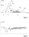
- FIG. 2 Two evaluation curves ZF 1 , ZF n , which are recorded in a first measuring cycle 1 and a later measuring cycle n, are shown schematically.
- the method according to the invention for detecting foam formation is illustrated in more detail using these two evaluation curves ZF 1 , ZF n :
- the measuring range h in the present case is divided into three sub-ranges s 1 , s 2 , s 3 , in which the first sub-range s 1 connects to the antenna of the level measuring device 1.
- the third section s 3 borders on the container bottom.
- the evaluation curves ZF 1 , ZF n each have a reflection maximum with corresponding amplitudes A m,1 A m, n at the measuring distance d, which corresponds to the surface of the filling material.
- the level measuring device 1 uses this maximum to determine the level L.
- the effect is used to detect foam formation that the evaluation curve ZF 1 , ZF n changes as the measuring cycles n progress, at least in individual partial areas s 1 , s 2 , s 3 .
- a reduction in the area f n towards progressive measurement cycles n, as visualized in the third subarea s 3 of the evaluation curve ZF n can be caused, for example, by foam formation in the filling material 3.
- the area f n in the third sub-area s 3 below the evaluation curves ZF 1 , ZF n can be defined as a characteristic value, with the level measuring device 1 also recording any change in the area f n in this sub-area s as the measuring cycles n progress 3 is determined.
- the level measuring device 1 can deduce from this that foam formation has occurred as a specific event-dependent condition.
- the amplitude A m,1 , A m,n of the fill level maximum can also be used as a characteristic value, not according to the present invention: If the amplitude A m,n falls below a predefined minimum amplitude A m
- ,min can be assigned to foam formation as an event-dependent state.
- Other causes for a weakening of the amplitude A m,1 , A m,n of the filling level maximum can lie, for example, in the boiling of the filling material 3 or a change in the dielectric value of the filling material 3.
- the number of maxima in the third sub-area s 3 ) can also be used as a characteristic value for monitoring over the measuring cycles n be used.
- a reduction in the number of peripheral maxima in the Evaluation curve ZF 1 , ZF n with increasing measuring cycles n can in turn be interpreted by the level measuring device 1 as foam formation.
- an area or amplitude of the evaluation curve ZF 1 , ZF n in the first partial area s 1 that increases with the measurement cycles n can, if this area is defined as a characteristic value to be monitored, be detected by the level measuring device 1 as a build-up on the antenna when a corresponding limit value is exceeded become.
- n can be used according to the invention to detect foam formation. This is shown as an example using the scatter ⁇ of the amplitude A m of the fill level maximum in Fig. 3 .
- the term “ scattering” is not limited to a special mathematical definition such as variance or mean square deviation. If the level measuring device 1 determines a scatter ⁇ of the amplitude as a characteristic value, which in turn is above a predetermined limit value, the level measuring device 1 can detect the operation of an agitator inside the container 2 as an event-dependent state, not according to the present invention. Conversely, falling below the scatter ⁇ from the level measuring device 1 can be interpreted as a failure of the agitator.
- foam formation can be assigned as an event-dependent state if the scatter ⁇ is exceeded. It goes without saying that in addition to the amplitude A m,1 , A m,n the spread ⁇ of other characteristic values, such as the spread of the area f n over previous measurement cycles n, can also be determined.
- the level measuring device 1 detects foam formation, it can use this on the one hand to declare or delete the level value L determined from the evaluation curve ZF 1 , ZF n as an untrustworthy incorrect measurement.
- the level measuring device 1 can transmit this to the higher-level unit 4. This makes it possible to react to the foam formation if necessary, for example by switching off a pump or a heater in the process system. This has to be the case Level measuring device 1 can be designed to output a corresponding electrical signal using a suitable bus protocol in the event of foam formation. Of course, if there is a display or one other (light) display on the level measuring device 1, foam formation can also be displayed graphically.
Landscapes
- Physics & Mathematics (AREA)
- Electromagnetism (AREA)
- Thermal Sciences (AREA)
- Fluid Mechanics (AREA)
- General Physics & Mathematics (AREA)
- Measurement Of Levels Of Liquids Or Fluent Solid Materials (AREA)
- Radar Systems Or Details Thereof (AREA)
Description
- Die Erfindung betrifft ein Verfahren zur Detektion von Schaumbildung eines Füllgutes in einem Behälter mittels eines Radar-basierten Füllstandsmessgerätes sowie ein Füllstandsmessgerät zur Ausführung dieses Verfahrens.
- In der Prozessautomatisierungstechnik werden allgemein Feldgeräte eingesetzt, die zur Erfassung oder zur Beeinflussung von Prozessvariablen dienen. Hierzu basiert die Funktionsweise der Feldgeräte auf jeweils geeigneten Messprinzipien, um die entsprechenden Prozessvariablen, wie Füllstand, Durchfluss, Druck, Temperatur, pH-Wert, Redoxpotential oder Leitfähigkeit zu erfassen. Verschiedenste solcher Feldgeräte-Typen werden von der Firma Endress + Hauser hergestellt und vertrieben.
- Zur Füllstandsmessung von Füllgütern in Behältern haben sich Radar-basierte Messverfahren etabliert, da sie robust und wartungsarm sind. Dabei werden unter dem Begriff "Behälter" im Rahmen der Erfindung auch nicht-abgeschlossene Behältnisse, wie beispielsweise Becken, Seen oder fließende Gewässer verstanden. Ein zentraler Vorteil Radar-basierter Messverfahren besteht in der Fähigkeit, den Füllstand quasi kontinuierlich messen zu können. Im Kontext dieser Patentanmeldung beziehen sich der Begriff "Radar" auf Signale bzw. elektromagnetische Wellen mit Frequenzen zwischen 0.03 GHz und 300 GHz. Übliche Frequenzbänder, bei denen Füllstandsmessung durchgeführt wird, liegen bei 2, 6 GHz 26 GHz oder 78 GHz.
- Im Fall von Radar-basierter Füllstandsmessung bildet das Pulslaufzeit-Prinzip ein etabliertes Messprinzip. Hierbei werden pulsförmige Mikrowellensignale zyklisch in Richtung des Füllguts ausgesandt und die Laufzeit bis zum Empfang des entsprechenden pulsförmigen Empfangssignals gemessen. Auf Basis dieses Messprinzips können Füllstandsmessgeräte mit vergleichsweise geringem schaltungstechnischem Aufwand realisiert werden. Ein Radar-basiertes Füllstandsmessgerät, welches nach dem Pulslaufzeit-Verfahren arbeitet, ist beispielsweise in der Offenlegungsschrift
DE 10 2012 104 858 A1 sowie in derEP 2 418 465 A1 beschrieben. - Sofern eine komplexere Schaltungstechnik in Kauf genommen werden kann, bietet sich zur Radar-basierten Füllstandsmessung auch FMCW ("Frequency Modulated Continuous Wave") als Messprinzip an. Bezüglich eines typischen Aufbaus von FMCW-basierten Füllstandsmessgeräten sei exemplarisch auf die Offenlegungsschrift
DE 10 2013 108 490 A1 verwiesen. - Das Messprinzip von FMCW- Radar basierten Entfernungsmessverfahren beruht darauf, das Mikrowellensignal zwar kontinuierlich, jedoch mit modulierter Frequenz auszusenden.
- Dabei liegt die Frequenz des Mikrowellensignals in einem festgelegten Frequenzband im Bereich einer standarisierten Mittenfrequenz. Kennzeichnend für FMCW ist hierbei, dass die Sende-Frequenz nicht konstant ist, sondern sich periodisch innerhalb des festgelegten Frequenzbandes ändert. Die zeitliche Änderung ist hierbei standardmäßig linear und weist eine Sägezahn- beziehungsweise Dreiecks-Form auf. Eine Sinus-förmige Änderung kann prinzipiell jedoch auch eingesetzt werden. Im Gegensatz zum Pulslaufzeit-Verfahren wird die Entfernung bzw. der Füllstand bei Implementierung des FMCW-Verfahrens auf Basis der instantanen Frequenzdifferenz zwischen dem aktuellen Empfangssignal und dem momentan ausgesendeten Mikrowellensignal bestimmt.
- Neben frei abstrahlender Radar-Messung, bei der das Mikrowellensignal über eine Antenne abgestrahlt bzw. empfangen wird, existiert zudem unabhängig vom Pulslaufzeit-Verfahren oder FMCW die Variante des geführten Radars. Hierbei wird das Mikrowellensignal über eine elektrisch leitfähige Sonde (bspw. ein Koaxial-Kabel oder einen Metallstab), die in den Behälter hinuntergelassen ist, geführt. Am Ort der Füllgutoberfläche wird in der Sonde das Empfangssignal generiert und entlang der Sonde gen Füllstandsmessgerät reflektiert. Bekannt ist diese Variante der Radar-basierten Füllstandsmessung auch unter dem Begriff "TDR" ("Time Domain Reflectometry"). Vorteilhaft an dieser Variante ist, dass aufgrund der geführten Signalabstrahlung weniger Leistung zum Betrieb des Füllstandsmessgerätes erforderlich ist.
- Bei jedem der oben genannten Messprinzipien (Pulslaufzeit und FMCW; unabhängig von geführter oder freier Abstrahlung) wird zur Ermittlung des Füllstandes anhand des Empfangssignals eine entsprechende Auswertungskurve aufgezeichnet. Im Falle des Pulsradar-basierten Verfahrens wird die Auswertungskurve aufgrund der hohen Pulsfrequenz durch Unterabtastung des reflektierten Empfangssignals erstellt. Dadurch bildet die Auswertungskurve das eigentliche, reflektierte Empfangssignal zeitgedehnt ab. Bei Implementierung des FMCW-Verfahrens wird die Auswertungskurve durch Mischen des momentan gesendeten Mikrowellensignals mit dem reflektierten Empfangssignal erstellt. Unabhängig vom Messprinzip spiegelt die Auswertungskurve die Amplitude des reflektierten Empfangssignals in Abhängigkeit der Messdistanz wieder.
- Der Füllstand wird aus der Auswertungskurve durch Detektion und örtlicher Zuweisung des entsprechenden lokalen Maximums bestimmt. Im Idealfall existiert neben dem Maximum, dass durch die Füllgut-Oberfläche erzeugt ist, kein weiteres Maximum. Bedingt durch weitere reflektierende Oberflächen im Behälter-Inneren erscheinen neben dem Füllstands-Maximum in der Auswertungskurve in der Praxis weitere entsprechende Maxima. Für die Füllstandsmessung ist jedoch allein das Maximum, das durch die Füllgut-Oberfläche erzeugt wird, relevant. Weitere Informationen in der Auswertungskurve werden daher nach Möglichkeit herausgefiltert, um die Füllstandsmessung verlässlicher zu machen.
- Je nach Prozessanlage kann es vorteilhaft sein, im Zuge der Füllstandsmessung weitere Ereignisse, wie Schaum- oder Ansatzbildung im Behälter, zu detektieren, um solchen Ereignissen eventuell gegensteuern zu können. Der Erfindung liegt daher die Aufgabe zugrunde, ein Füllstandsmessgerät bereitzustellen, mit dem neben dem Füllstand eine Schaumbildung im Zusammenhang mit der Füllstandsmessung detektierbar ist.
- Die Erfindung löst diese Aufgabe durch ein Verfahren zur Detektion eines Ereignis-abhängigen Zustandes mittels eines Radar-basierten Füllstandsmessgerätes, das zur Messung eines Füllstandes eines in einem Behälter befindlichen Füllgutes dient. Das Verfahren umfasst folgende Verfahrensschritte, die in aufeinanderfolgenden Messzyklen wiederholt werden:
- Aussenden eines Mikrowellensignals in Richtung des Füllgutes,
- Empfang eines Empfangssignals nach Reflektion des Mikrowellensignals im Inneren des Behälters,
- Erstellung einer Auswertungskurve anhand von zumindest dem Empfangssignal, wobei die Auswertungskurve derart erstellt wird, dass eine Signalstärke des Empfangssignals in Abhängigkeit der Messdistanz wiedergegeben wird,
- Erfassung eines vordefinierten Kennwertes der Auswertungskurve innerhalb des Messbereichs oder zumindest eines vordefinierten Teilbereichs vom Messbereich.
- Über fortschreitende Messzyklen wird erfindungsgemäß eine Änderung und/oder eine Streuung des Kennwertes ermittelt. Dabei wird der Ereignis-abhängige Zustand detektiert, sofern die Änderung bzw. die Streuung einen vordefinierten Grenzwert überschreitet.
- Ein Ereignis-abhängiger Zustand ist im Sinne der Erfindung eine Schaumbildung. Bei Detektion eines solchen Ereignis-abhängigen Zustandes durch das Füllstandsmessgerät kann diese Information also beispielsweise der Prozessanlagen-Steuerung übermittelt werden, um hierauf basierend entsprechende Steuerbefehle, wie das Abstellen einer Heizung oder das Abstellen eines Rührwerkes, auszugeben.
- Die erfindungsgemäße Lösung bietet somit den Vorteil, dass einer Anlagen-Steuerung automatisiert und ohne zusätzliche Messinstrumente das Auftreten von Schaumbildung im Behälter mitgeteilt werden kann. Somit kann die Betriebssicherheit der gesamten Prozess-Anlage erhöht werden.
- Der Kennwert, aus der der Auswertungskurve erfasst wird, ist erfindungsgemäß zumindest in einem Teilbereich des Messbereichs die Fläche unter der Auswertungskurve. Somit ist es möglich, die aus diesem Teilbereich reflektierte Leistung des Empfangssignals zu bestimmen. Eine Abnahme der Leistung in einem weiter entfernten Teilbereich bis unterhalb eines entsprechenden Grenzwertes kann durch Schaumbildung hervorgehrufen werden.
- Analog zum erfindungsgemäßen Verfahren wird die Aufgabe, die der Erfindung zugrunde liegt, außerdem durch ein Radar-basiertes Füllstandsmessgerät gelöst, das zur Durchführung des Verfahrens nach zumindest einer der zuvor genannten Ausführungsvarianten ausgeführt ist. Dementsprechend umfasst es folgende Komponenten:
- Eine Signalerzeugungs-Einheit, die ausgelegt ist, in aufeinanderfolgenden Messzyklen jeweils ein Mikrowellensignal in Richtung des Füllgutes auszusenden,
- Eine Empfangseinheit, die konzipiert ist, um nach Reflektion des Mikrowellensignals im Inneren des Behälters ein Empfangssignal zu empfangen,
- eine Auswertungseinheit, die ausgelegt ist, um
- ∘ anhand von zumindest dem Empfangssignal pro Messzyklus eine Auswertungskurve, die eine Signalstärke des Empfangssignals in Abhängigkeit der Messdistanz wiedergibt, zu erstellen,
- ∘ innerhalb zumindest eines festgelegten Teilbereichs des Messbereichs eine Fläche unter der Auswertungskurve zu erfassen,
- ∘ über fortschreitende Messzyklen eine Änderung und/oder eine Streuung der Fläche zu ermitteln,
- ∘ Schaumbildung zu detektieren, sofern die Änderung bzw. die Streuung einen vordefinierten Grenzwert überschreitet,
- ∘ zumindest sofern die Änderung bzw. die Streuung einen vordefinierten Grenzwert nicht überschreitet, mittels der Auswertungskurve den Füllstand zu bestimmen.
- Unter dem Begriff "Einheit" wird im Rahmen der Erfindung prinzipiell jede elektronische Schaltung verstanden, die für ihren Einsatzzweck geeignet ausgelegt ist. Es kann sich also je nach Anforderung um eine Analogschaltung zur Erzeugung bzw. Verarbeitung entsprechender analoger Signale handeln. Es kann sich jedoch auch um eine (halbleiterbasierte) Digitalschaltung wie einem FPGA oder einen Speichermedium in Zusammenwirken mit einem Programm handeln. Dabei ist das Programm ausgelegt, die entsprechenden Verfahrensschritte durchzuführen bzw. die notwendigen Rechenoperationen der jeweiligen Einheit anzuwenden. In diesem Kontext können verschiedene elektronische Einheiten des Füllstandsmessgerätes im Sinne der Erfindung potentiell auch auf einen gemeinsamen physikalischen Speicher zurückgreifen bzw. mittels derselben physikalischen Digitalschaltung betrieben werden.
- In einer weitergehenden Ausführungsform des Füllstandsmessgerätes kann die Auswertungseinheit vorzugsweise so ausgelegt werden, dass bei Über- bzw. Unterschreitung des Grenzwertes das Auftreten des spezifischen Ereignis-Zustandes, insbesondere graphisch oder als elektrisches Signal, ausgegeben wird. Ein entsprechendes elektrisches Signal kann beispielsweise mittels eines geeigneten Bussystems an die Anlagen-Steuerung übermittelt werden.
- Auch ist es möglich, das Füllstandsmessgerät je nach Definition des Ereignis-abhängigen Zustandes so auszulegen, dass, sofern die Änderung bzw. die Streuung den vordefinierten Grenzwert über- bzw. unterschreitet, kein neuer Füllstandswert aus der aktuellen Auswertungskurve bestimmt wird.
- Zudem ist es von Vorteil, wenn der Teilbereich zur Erfassung des Kennwertes manuell am Füllstandsmessgerät konfigurierbar ist. Somit lässt sich das Füllstandsmessgerät an den jeweiligen Behälter bzw. an das jeweilige Füllgut anpassen. Sofern beispielsweise die Antenne aufgrund von staubhaltigem oder feuchtem Füllgut zu Ansatzbildung neigt, kann der Teilbereich manuell an die Stelle des Messbereichs gesetzt werden, die an die Antenne angrenzt. Falls in der Mitte des Behälters bzw. des Messbereichs ein Rührwerk vorhanden ist, so kann der Teilbereich, in dem der Kennwert ermittelt werden soll, an diese Stelle des Messbereichs gesetzt werden.
- Anhand der nachfolgenden Figuren wird die Erfindung näher erläutert. Es zeigt:
-
Fig. 1 : Eine Anordnung eines Radar-Füllstandsmessgerätes, -
Fig. 2 : einen schaltungstechnischen Aufbau des Füllstandsmessgerätes, und -
Fig. 3 : eine erfindungsgemäße Auswertungskurve. - Zum Verständnis der Erfindung ist in
Fig. 1 eine typische Anordnung eines frei abstrahlenden, Radar-basierten Füllstandsmessgerätes 1 an einem Behälter 2 gezeigt. In dem Behälter 2 befindet sich ein Füllgut 3, dessen Füllstand L durch das Füllstandsmessgerät 1 zu bestimmen ist. Dazu ist das Füllstandsmessgerät 1 oberhalb des maximal zulässigen Füllstands L am Behälter 2 angebracht. Je nach Einsatzgebiet kann die Einbauhöhe h des Füllstandsmessgerätes 1 über dem Behälterboden bis zu mehr als 100 m betragen. - In der Regel ist das Füllstandsmessgerät 1 über ein Bussystem, etwa "Ethernet", "PROFIBUS", "HART" oder "Wireless HART" mit einer übergeordneten Einheit 4, beispielsweise einem Prozessleitsystem oder einer dezentralen Datenbank verbunden. Hierüber können zum einen Informationen über den Betriebszustand des Füllstandsmessgerätes 1 kommuniziert werden. Über das Bussystem können jedoch auch Informationen über den Füllstand L übermittelt werden, um gegebenenfalls am Behälter 2 vorhandene Zu- oder Abflüsse zu steuern.
- Da das in
Fig. 1 dargestellte Füllstandsmessgerät 1 als frei abstrahlendes Radar ausgelegt ist, umfasst es eine entsprechende Antenne. Dabei kann die Antenne, wie angedeutet, beispielswiese als Hornantenne ausgelegt sein. Insbesondere bei Radar-Frequenzen oberhalb von 100 GHz kann die Antenne auch als Planar-Antenne realisiert sein. Unabhängig von der Bauform ist die Antenne so ausgerichtet, dass entsprechende Mikrowellensignale SHF in Richtung des Füllgutes 3 ausgesendet werden. - An der Oberfläche des Füllgutes 3 werden die Mikrowellensignale SHF reflektiert und nach einer korrespondierenden Signallaufzeit an der Antenne des Füllstandsmessgerätes 1 entsprechend als Empfangssignale EHF empfangen. Hierbei hängt die Signallaufzeit der Mikrowellensignale SHF, EHF von der Entfernung d = h - L des Füllstandsmessgerätes 1 zur Füllgut-Oberfläche ab.
- Oftmals unterläuft das Füllgut 3 während der Füllstandsmessung eine chemische Reaktion, einen Mahl- oder einen Rührprozess. Daher weist das Füllgut 3 entgegen der in
Fig. 1 gezeigten Darstellung gegebenenfalls eine schäumende Füllgut-Oberfläche auf. Bedingt durch hohe Temperaturen oder staubhaltige Atmosphäre kann sich zudem Ansatz an der Behälter-Innenwand oder an der Antenne bilden. Dementsprechend können solche Zustände im Zuge der Füllstandsmessung zur Ermittlung eines ungenauen oder falschen Füllstandswertes L führen. Daher ist es zum Betrieb der Prozessanlage vorteilhaft, die einzelnen Zustände erkennen zu können, um im simpelsten Fall eine chemische Reaktion, beispielsweise bei ungewollter Schaumbildung, zu stoppen, indem ein Zufluss gestoppt oder eine Heizung heruntergeregelt wird. - Erfindungsgemäß kann Schaumbildung anhand der vom Füllstandsmessgerät 1 erstellten Auswertungskurve ZF1, ZFn erkannt werden. Dabei erstellt das Füllstandsmessgerät 1 die Auswertungskurve ZF1, ZFn bei Implementierung des FMCW-Verfahrens prinzipiell durch Mischen des momentan empfangenen Empfangssignals EHF mit dem derzeit ausgesendeten Mikrowellensignal SHF, wobei das Mikrowellensignal SHF hierzu kontinuierlich und innerhalb des Frequenzbandes mit sägezahnförmiger Frequenz-Änderung ausgesendet wird.
- Im Fall des Pulslaufzeit-Verfahrens wird die Auswertungskurve ZF1, ZFn durch Unterabtastung des pulsförmigen Empfangssignals EHF erstellt, wobei die Pulsfrequenz des Abtastsignals hierzu geringfügig von der Pulsfrequenz des Mikrowellensignals SHF bzw. des Empfangssignals EHF abweicht.
- Sowohl bei FMCW, als auch beim Pulslaufzeit-Verfahren stellt die Auswertungskurve ZF1, ZFn die Signalamplitude A des Empfangssignals EHF in Abhängigkeit der Messdistanz d wieder. Im Falle der Füllstandsmessung erstreckt sich der korrespondierende Messbereich h dementsprechend von der Antenne des Füllstandsmessgerätes 1 bis zum Boden des Behälters 2. Den Füllstand L kann das Füllstandsmessgerät 1 anhand der Auswertungskurve ZF1, ZFn ermitteln, da die Reflektion des Mikrowellensignals SHF an der Füllgut-Oberfläche in der Auswertungskurve ZF1, ZFn ein lokales Maximum Am,1, Am,n erzeugt. Da das Füllstandsmessgerät 1 ausgelegt ist, um zu dem lokalen Maximum Am,1, Am,n den korrespondierenden Abstand d zu ermitteln, kann das Füllstandsmessgerät 1 hieraus den Füllstand L berechnen.
- In
Fig. 2 sind zwei Auswertungskurven ZF1, ZFn, die in einem ersten Messzyklus 1 sowie einem späteren Messzyklus n aufgenommen sind, schematisch dargestellt. Anhand dieser zwei Auswertungskurven ZF1, ZFn wird das erfindungsgemäße Verfahren zur Detektion einer Schaumbildung näher veranschaulicht: Wie erkennbar wird, ist der Messbereich h im vorliegenden Fall in drei Teilbereiche s1, s2, s3 untergliedert, bei denen der erste Teilbereich s1 an die Antenne des Füllstandsmessgerätes 1 anschließt. Der dritte Teilbereich s3 grenzt an den Behälterboden. In dem zweiten, mittleren Teilbereich s2 weisen die Auswertungskurven ZF1, ZFn an der Messdistanz d, die der Füllgut-Oberfläche entspricht, jeweils ein Reflexions-Maximum mit entsprechenden Amplituden Am,1 Am,n auf. Dieses Maximum zieht das Füllstandsmessgerät 1 zur Bestimmung des Füllstandes L heran. - Erfindungsgemäß wird zur Detektion von Schaumbildung der Effekt genutzt, dass sich die Auswertungskurve ZF1, ZFn, mit fortschreitenden Messzyklen n zumindest in einzelnen Teilbereichen s1, s2, s3 verändert. Eine Verringerung der Fläche fn hin zu fortschreitenden Messzyklen n, wie es im dritten Teilbereich s3 der Auswertungskurve ZFn visualisiert ist, kann beispielsweise durch eine Schaumbildung des Füllgutes 3 bedingt sein. Erfindungsgemäß kann daher bei diesem Ereignis-Zustand die Fläche fn im dritten Teilbereich s3 unterhalb der Auswertungskurven ZF1, ZFn als Kennwert definiert werden, wobei vom Füllstandsmessgerät 1 außerdem mit fortschreitenden Messzyklen n die etwaige Änderung der Fläche fn in diesem Teilbereich s3 ermittelt wird. Wenn als Grenzwert eine zuvor definierte Mindestfläche unterschritten wird, kann das Füllstandsmessgerät 1 hieraus ableiten, dass als konkreter Ereignis-abhängiger Zustand eine Schaumbildung eingetreten ist. In diesem Zusammenhang bietet es sich erfindungsgemäß an, das Füllstandsmessgerät 1 so auszulegen, dass die Anzahl und die jeweilige Position der Teilbereiche s1, s2, s3 manuell an den jeweiligen Behälter 2 bzw. das Füllgut 3 angepasst werden kann.
- Neben der Fläche fn kann, nicht gemäß der vorliegenden Erfindung, auch die Amplitude Am,1, Am,n des Füllstands-Maximums als Kennwert herangezogen werden: Eine Unterschreitung der Amplitude Am,n unter eine vordefinierte Mindest-Amplitude Am,min kann beispielsweise einer Schaumbildung als Ereignis-abhängigem Zustand zugeordnet werden. Andere Ursachen für eine Abschwächung der Amplitude Am,1, Am,n des Füllstands-Maximums können z.B. im Aufkochen des Füllgutes 3 bzw. einer Änderung des dielektrischen Wertes des Füllgutes 3 liegen.
- Alternativ zu der Fläche fn oder der Amplitude Am,i, Am,n kann, nicht gemäß der vorliegenden Erfindung, auch die Anzahl der Maxima (im dritten Teilbereich s3) als Kennwert zur Überwachung über die Messzyklen n herangezogen werden. Eine Verringerung der Anzahl an peripheren Maxima in der Auswertungskurve ZF1, ZFn mit steigenden Messzyklen n kann durch das Füllstandsmessgerät 1 wiederum als Schaumbildung interpretiert werden.
- Eine mit den Messzyklen n zunehmende Fläche bzw. Amplitude der Auswertungskurve ZF1, ZFn im ersten Teilbereich s1 kann hingegen, sofern diese Fläche als zu überwachender Kennwert definiert ist, bei Übersteigen eines entsprechenden Grenzwertes durch das Füllstandsmessgerät 1 als Ansatzbildung an der Antenne detektiert werden.
- Nicht nur eine Änderung eines möglichen Kennwertes, sondern auch dessen Streuung σ über die vergangenen Messzyklen n kann erfindungsgemäß herangezogen werden, um Schaumbildung zu detektieren. Beispielshaft dargestellt ist dies anhand der Streuung σ der Amplitude Am des Füllstands-Maximums in
Fig. 3 . Dabei ist der Begriff "Streuung" nicht auf eine spezielle mathematische Definition wie die Varianz oder die mittlere quadratische Abweichung beschränkt. Sofern das Füllstandsmessgerät 1 als Kennwert eine Streuung σ der Amplitude ermittelt, die wiederum oberhalb eines vorbestimmten Grenzwertes liegt, so kann das Füllstandsmessgerät 1 als Ereignis-abhängigen Zustand, nicht gemäß der vorliegenden Erfindung, den Betrieb eines Rührwerkes im Inneren des Behälters 2 detektieren. Umgekehrt kann das Unterschreiten der Streuung σ vom Füllstandsmessgerät 1 als Ausfall des Rührwerkes interpretiert werden. - Je nachdem, wie hoch der Grenzwert für die Streuung σ gewählt ist, kann bei Überschreiten der Streuung σ als Ereignis-abhängiger Zustand eine Schaumbildung zugeordnet werden. Es versteht sich von selbst, dass neben der Amplitude Am,1, Am,n auch die Streuung σ anderer Kennwerte, wie die Streuung der Fläche fn über vorangehende Messzyklen n ermittelt werden kann.
- Sofern das Füllstandsmessgerät 1 eine Schaumbildung detektiert, kann es dies einerseits nutzen, um den aus der Auswertungskurve ZF1, ZFn ermittelten Füllstandswert L als nicht vertrauenswürdige Falschmessung zu deklarieren bzw. zu löschen.
- Andererseits kann das Füllstandsmessgerät 1 bei Detektion einer Schaumbildung diese an die übergeordnete Einheit 4 übermitteln. Hierdurch kann gegebenenfalls auf die Schaumbildung reagiert werden, bspw. durch Abschalten einer Pumpe oder einer Heizung in der Prozessanlage. Hierzu muss das Füllstandsmessgerät 1 so ausgelegt sein, um im Falle einer Schaumbildung ein entsprechendes elektrisches Signal mittels eines geeigneten Bus-Protokolls auszugeben. Natürlich kann bei Vorhandensein eines Displays oder einer sonstigen (Leucht-) Anzeige am Füllstandsmessgerät 1 eine Schaumbildung auch graphisch angezeigt werden.
-
- 1
- Füllstandsmessgerät
- 2
- Behälter
- 3
- Füllgut
- 4
- Übergeordnete Einheit
- A
- Amplitude
- d
- Messdistanz
- EHF
- Empfangssignale
- fn
- Fläche unter der Auswertungskurve
- h
- Einbauhöhe bzw. Messbereich
- L
- Füllstand
- n
- Messzyklus
- SHF
- Mikrowellensignale
- s1,2,3
- Teilbereiche des Messbereichs
- ZF1,n
- Auswertungskurven
- σ
- Streuung
Claims (4)
- Verfahren zur Detektion von Schaumbildung eines Füllgutes (3) in einem Behälter (2) mittels eines Radar-basierten Füllstandsmessgerätes (1), das zur Messung eines Füllstandes (L) des Füllgutes (3) im Behälter (2) dient, wobei das Verfahren folgende Verfahrensschritte, die in aufeinanderfolgenden Messzyklen (n) wiederholt werden, umfasst:- Aussenden eines Mikrowellensignals (SHF) in Richtung des Füllgutes (3),- Empfang eines Empfangssignals (EHF) nach Reflektion des Mikrowellensignals (SHF) im Inneren des Behälters (2),- Erstellung einer Auswertungskurve (ZF) anhand von zumindest dem Empfangssignal (EHF), wobei die Auswertungskurve (ZF) derart erstellt wird, dass eine Signalstärke (A) des Empfangssignals (EHF) in Abhängigkeit der Messdistanz (d) wiedergegeben wird,gekennzeichnet durch:- Erfassung der Fläche (fn) in zumindest einem Teilbereich (s1, s2, s3) unter der Auswertungskurve (ZFn),wobei über fortschreitende Messzyklen (n) eine Änderung und/oder eine Streuung (σ) der Fläche (fn) ermittelt wird,wobei Schaumbildung detektiert wird, sofern die Änderung bzw. die Streuung (σ) einen vordefinierten Grenzwert (Am,lim) überschreitet.
- Radar-basiertes Füllstandsmessgerät ausgeführt zur Durchführung des Verfahrens nach
Anspruch 1, folgende Komponenten umfassend:- Eine Signalerzeugungs-Einheit, die ausgelegt ist, in aufeinanderfolgenden Messzyklen (n) jeweils ein Mikrowellensignal (SHF) in Richtung des Füllgutes (3) auszusenden,- Eine Empfangseinheit, die konzipiert ist, um nach Reflektion des Mikrowellensignals (SHF) im Inneren des Behälters (2) ein Empfangssignal (EHF) zu empfangen,- eine Auswertungseinheit, die ausgelegt ist, um∘ anhand von zumindest dem Empfangssignal (EHF) pro Messzyklus (n) eine Auswertungskurve (ZF), die eine Signalstärke (A) des Empfangssignals (EHF) in Abhängigkeit der Messdistanz (d) wiedergibt, zu erstellen,∘ innerhalb zumindest eines festgelegten Teilbereichs (s1, s2, s3) des Messbereichs (h) eine Fläche (fn) unter der Auswertungskurve (ZF) zu erfassen,∘ über fortschreitende Messzyklen (n) eine Änderung und/oder eine Streuung (σ) der Fläche (fn) zu ermitteln,∘ Schaumbildung zu detektieren, sofern die Änderung bzw. die Streuung (σ) einen vordefinierten Grenzwert (Am,lim) überschreitet,∘ zumindest, sofern die Änderung bzw. die Streuung (σ) einen vordefinierten Grenzwert (Am,lim) nicht überschreitet, mittels der Auswertungskurve (ZF) den Füllstand (L) zu bestimmen. - Füllstandsmessgerät nach Anspruch 2, wobei die Auswertungseinheit ausgelegt ist, um das Auftreten von Schaumbildung, insbesondere graphisch oder als elektrisches Signal, auszugeben.
- Füllstandsmessgerät nach Anspruch 2 oder 3, wobei der Teilbereich (s1, s2, s3) zur Erfassung des Kennwertes (Am, f) manuell konfigurierbar ist.
Applications Claiming Priority (2)
| Application Number | Priority Date | Filing Date | Title |
|---|---|---|---|
| DE102018123432.5A DE102018123432A1 (de) | 2018-09-24 | 2018-09-24 | Detektion von Ereignis-abhängigen Zuständen bei Füllstandsmessung |
| PCT/EP2019/072075 WO2020064216A1 (de) | 2018-09-24 | 2019-08-19 | Detektion von ereignis-abhängigen zuständen bei füllstandsmessung |
Publications (2)
| Publication Number | Publication Date |
|---|---|
| EP3857184A1 EP3857184A1 (de) | 2021-08-04 |
| EP3857184B1 true EP3857184B1 (de) | 2023-12-06 |
Family
ID=67667863
Family Applications (1)
| Application Number | Title | Priority Date | Filing Date |
|---|---|---|---|
| EP19755902.4A Active EP3857184B1 (de) | 2018-09-24 | 2019-08-19 | Detektion von schaumbildung eines füllgutes in einem behälter bei einer füllstandsmessung |
Country Status (5)
| Country | Link |
|---|---|
| US (1) | US12111198B2 (de) |
| EP (1) | EP3857184B1 (de) |
| CN (1) | CN112739994B (de) |
| DE (1) | DE102018123432A1 (de) |
| WO (1) | WO2020064216A1 (de) |
Families Citing this family (6)
| Publication number | Priority date | Publication date | Assignee | Title |
|---|---|---|---|---|
| BE1029417B1 (fr) * | 2021-05-20 | 2022-12-19 | Jac S A | Fermenteur et procédé pour produire du levain liquide |
| BE1029418B1 (fr) * | 2021-05-20 | 2022-12-19 | Jac S A | Fermenteur et procédé pour produire du levain liquide avec une vitesse d'agitation variable |
| HUE068614T2 (hu) * | 2022-04-19 | 2025-01-28 | Grieshaber Vega Kg | Szintmérõ készülék választható jósági fokozatú monitorozási funkcióval |
| US20250044138A1 (en) * | 2023-08-02 | 2025-02-06 | AlphaHive LLC | Multiple radar transmitter/receiver liquid level sensor systems and methods for mobile, low profile storage tanks |
| US20250044141A1 (en) * | 2023-08-02 | 2025-02-06 | AlphaHive LLC | Mobile, low profile storage tank sensor monitoring analytic management system and methods |
| US12228445B1 (en) * | 2024-01-27 | 2025-02-18 | Barrel Proof Technologies Llc | System and method for determining alcohol content within container utilizing container monitoring system |
Citations (1)
| Publication number | Priority date | Publication date | Assignee | Title |
|---|---|---|---|---|
| EP2418465A1 (de) * | 2010-07-19 | 2012-02-15 | VEGA Grieshaber KG | Amplitudenprofilierung in Füllstandmessgeräten |
Family Cites Families (32)
| Publication number | Priority date | Publication date | Assignee | Title |
|---|---|---|---|---|
| US4958295A (en) * | 1986-05-21 | 1990-09-18 | Hercules Incorporated | Analyzing apparatus and method for analysis of liquid samples |
| DE4332071C2 (de) * | 1993-09-21 | 1995-09-07 | Endress Hauser Gmbh Co | Verfahren zur Füllstandsmessung nach dem Radarprinzip |
| US6338790B1 (en) * | 1998-10-08 | 2002-01-15 | Therasense, Inc. | Small volume in vitro analyte sensor with diffusible or non-leachable redox mediator |
| DE10139242A1 (de) * | 2001-08-09 | 2003-03-06 | Grieshaber Vega Kg | Verfahren und Vorrichtung zum Erfassen eines Befüllvorgangs |
| DE10300760A1 (de) * | 2002-01-23 | 2003-08-14 | Siemens Vdo Automotive Corp | Verfahren zum Erkennen eines fehlerhaft arbeitenden Tankfüllstandsmeldesystems |
| US7117108B2 (en) * | 2003-05-28 | 2006-10-03 | Paul Ernest Rapp | System and method for categorical analysis of time dependent dynamic processes |
| DE10360711A1 (de) * | 2003-12-19 | 2005-07-14 | Endress + Hauser Gmbh + Co. Kg | Füllstandsmeßgerät und Verfahren zur Füllstandsmessung und -überwachung |
| SE0403165D0 (sv) * | 2004-12-23 | 2004-12-23 | Saab Rosemount Tank Radar Ab | A radar level gauge system |
| US7355548B2 (en) * | 2005-09-01 | 2008-04-08 | Rosemount Tank Radar Ab | Processing of tank signal in radar level gauge system |
| US7733224B2 (en) * | 2006-06-30 | 2010-06-08 | Bao Tran | Mesh network personal emergency response appliance |
| DE102006019191A1 (de) * | 2006-04-21 | 2007-10-25 | Endress + Hauser Gmbh + Co. Kg | Verfahren zur Ermittlung und Überwachung des Füllstands eines Mediums in einem Behälter |
| DE102006058852B4 (de) * | 2006-12-13 | 2014-01-02 | Vega Grieshaber Kg | Verfahren und Vorrichtung zur Korrektur nichtidealer Zwischenfrequenzsignale bei Abstandsmessgeräten nach dem FMCW-Prinzip |
| DE102006062606A1 (de) * | 2006-12-29 | 2008-07-03 | Endress + Hauser Gmbh + Co. Kg | Verfahren zur Ermittlung und Überwachung des Füllstands eines Mediums in einem Behälter nach einem Laufzeitverfahren |
| DE102009055262A1 (de) * | 2009-12-23 | 2011-06-30 | Endress + Hauser GmbH + Co. KG, 79689 | Verfahren zur Ermittlung und Überwachung des Füllstands eines Mediums in einem Behälter nach einem Laufzeitmessverfahren |
| CA2699596A1 (fr) * | 2010-03-24 | 2011-09-24 | Hydro-Quebec | Systeme et methode de synchronisation de phase de signaux produits par des unites de mesure respectives |
| US8813559B2 (en) * | 2010-12-16 | 2014-08-26 | Vega Grieshaber Kg | Determination of media characteristics in fill-level measuring |
| DE102010063430A1 (de) * | 2010-12-17 | 2012-06-21 | Endress + Hauser Gmbh + Co. Kg | Verfahren zur Überwachung der Funktion eines Feldgeräts |
| DE102011017448A1 (de) * | 2011-04-18 | 2012-10-18 | Krones Aktiengesellschaft | Verfahren zum Betreiben einer Behältnisbehandlungsanlage mit Störungsdiagnose |
| DE102011082367A1 (de) * | 2011-09-08 | 2013-03-14 | Endress + Hauser Gmbh + Co. Kg | Verfahren zur Füllstandsmessung nach dem Laufzeitprinzip |
| DE102012003373B4 (de) * | 2012-02-22 | 2018-11-22 | Krohne Messtechnik Gmbh | Verfahren zur Überwachung und Verfahren zum Betreiben eines nach dem Radar-Prinzip arbeitenden Füllstandmesssystems und entsprechendes Füllstandmesssystem |
| DE102012104858A1 (de) * | 2012-06-05 | 2013-12-05 | Endress + Hauser Gmbh + Co. Kg | Verfahren zur Füllstandsmessung nach dem Laufzeitprinzip |
| DE102012109101A1 (de) * | 2012-09-26 | 2014-03-27 | Endress + Hauser Gmbh + Co. Kg | Füllstandsmessgerät |
| US9322699B2 (en) * | 2013-07-03 | 2016-04-26 | Rosemount Tank Radar Ab | Radar level gauge and methods of testing radar level gauge and system |
| DE102013108490A1 (de) | 2013-08-07 | 2015-02-12 | Endress + Hauser Gmbh + Co. Kg | Dispersionskorrektur für FMCW-Radar in einem Rohr |
| US9778089B2 (en) * | 2014-06-30 | 2017-10-03 | Rosemount Tank Radar Ab | Multi-channel guided wave radar level gauge |
| US20170211963A1 (en) * | 2014-07-21 | 2017-07-27 | Omid TAHERI | Methods and system for determining pulse temporal coordinates overlapping pulses in a reflected radar signal |
| US10055519B2 (en) * | 2014-10-23 | 2018-08-21 | Honeywell International Inc. | Pulse shape change for interface determination |
| DE102015115462A1 (de) * | 2015-09-14 | 2017-03-16 | Endress+Hauser Gmbh+Co. Kg | Verfahren zur Messung des Füllstands eines in einem Behälter befindlichen Füllgutes |
| EP3524962A1 (de) * | 2015-12-09 | 2019-08-14 | Diamontech GmbH | Vorrichtung und verfahren zum analysieren eines stoffs |
| US10386180B2 (en) * | 2016-11-28 | 2019-08-20 | Honeywell International Inc. | Apparatus and method for measuring thin material thicknesses in inventory management applications |
| DE102017100269A1 (de) * | 2017-01-09 | 2018-07-12 | Endress+Hauser SE+Co. KG | Verfahren zur Detektion eines Fehlerzustandes an einem FMCW-basierten Füllstandsmessgerät |
| CN108195443B (zh) * | 2017-12-29 | 2020-10-02 | 北京奥特美克科技股份有限公司 | 水位测量方法、系统及设备 |
-
2018
- 2018-09-24 DE DE102018123432.5A patent/DE102018123432A1/de not_active Withdrawn
-
2019
- 2019-08-19 EP EP19755902.4A patent/EP3857184B1/de active Active
- 2019-08-19 US US17/278,813 patent/US12111198B2/en active Active
- 2019-08-19 WO PCT/EP2019/072075 patent/WO2020064216A1/de not_active Ceased
- 2019-08-19 CN CN201980059734.8A patent/CN112739994B/zh active Active
Patent Citations (1)
| Publication number | Priority date | Publication date | Assignee | Title |
|---|---|---|---|---|
| EP2418465A1 (de) * | 2010-07-19 | 2012-02-15 | VEGA Grieshaber KG | Amplitudenprofilierung in Füllstandmessgeräten |
Also Published As
| Publication number | Publication date |
|---|---|
| CN112739994B (zh) | 2025-01-28 |
| WO2020064216A1 (de) | 2020-04-02 |
| DE102018123432A1 (de) | 2020-03-26 |
| US20220034700A1 (en) | 2022-02-03 |
| US12111198B2 (en) | 2024-10-08 |
| CN112739994A (zh) | 2021-04-30 |
| EP3857184A1 (de) | 2021-08-04 |
Similar Documents
| Publication | Publication Date | Title |
|---|---|---|
| EP3746752B1 (de) | Füllstandsmessgerät | |
| EP3857184A1 (de) | Detektion von ereignis-abhängigen zuständen bei füllstandsmessung | |
| EP3861305B1 (de) | Verfahren zur füllstandsmessung | |
| DE102009001010B4 (de) | Verfahren zur Ermittlung und Überwachung des Füllstands eines Mediums in einem Behälter nach einem Laufzeitmessverfahren | |
| EP2418465A1 (de) | Amplitudenprofilierung in Füllstandmessgeräten | |
| WO2019115117A1 (de) | Verfahren zur vereinfachten inbetriebnahme eines feldgeräts | |
| WO2023099269A1 (de) | Füllstandsmessgerät | |
| EP3746753B1 (de) | Verfahren zur detektion von potentiellen fehlerzuständen an einem fmcw-basierten füllstandsmessgerät | |
| WO2006063933A2 (de) | Nach dem laufzeitprinzip arbeitendes füllstandsmessgerät und verfahren zu dessen inbetriebnahme | |
| WO2018127356A1 (de) | Verfahren zur detektion eines fehlerzustandes an einem fmcw-basierten füllstandsmessgerät | |
| EP3887777B1 (de) | Verfahren zu füllstandsmessung | |
| DE102022105197A1 (de) | Füllstandsmessgerät | |
| WO2021175813A1 (de) | Füllstandsmessgerät | |
| EP3837509B1 (de) | Füllstandsmessgerät | |
| WO2019096466A1 (de) | Verfahren zur erstellung einer ausblendkurve für ein füllstandsmessgerät | |
| DE102022105195A1 (de) | Füllstandsmessgerät | |
| EP3874242B1 (de) | Füllstandsmessgerät | |
| DE102022128393A1 (de) | Ortsauflösende Füllstandsmessung | |
| EP4070048B1 (de) | Füllstandsmessgerät | |
| EP3894806B1 (de) | Verfahren zur füllstandsmessung und radar-basiertes füllstandsmessgerät | |
| DE102024111077A1 (de) | Füllstandsanzeige-Vorrichtung | |
| WO2025237816A1 (de) | Füllstandsmessgerät | |
| WO2025131443A1 (de) | Füllvolumen-ermittlung in behältern | |
| EP4716829A1 (de) | Verfahren zur bestimmung eines rohr-innendurchmessers eines schwallrohres durch ein füllstandsmessgerät |
Legal Events
| Date | Code | Title | Description |
|---|---|---|---|
| STAA | Information on the status of an ep patent application or granted ep patent |
Free format text: STATUS: UNKNOWN |
|
| STAA | Information on the status of an ep patent application or granted ep patent |
Free format text: STATUS: THE INTERNATIONAL PUBLICATION HAS BEEN MADE |
|
| PUAI | Public reference made under article 153(3) epc to a published international application that has entered the european phase |
Free format text: ORIGINAL CODE: 0009012 |
|
| STAA | Information on the status of an ep patent application or granted ep patent |
Free format text: STATUS: REQUEST FOR EXAMINATION WAS MADE |
|
| 17P | Request for examination filed |
Effective date: 20210225 |
|
| AK | Designated contracting states |
Kind code of ref document: A1 Designated state(s): AL AT BE BG CH CY CZ DE DK EE ES FI FR GB GR HR HU IE IS IT LI LT LU LV MC MK MT NL NO PL PT RO RS SE SI SK SM TR |
|
| DAV | Request for validation of the european patent (deleted) | ||
| DAX | Request for extension of the european patent (deleted) | ||
| STAA | Information on the status of an ep patent application or granted ep patent |
Free format text: STATUS: EXAMINATION IS IN PROGRESS |
|
| 17Q | First examination report despatched |
Effective date: 20230103 |
|
| GRAP | Despatch of communication of intention to grant a patent |
Free format text: ORIGINAL CODE: EPIDOSNIGR1 |
|
| STAA | Information on the status of an ep patent application or granted ep patent |
Free format text: STATUS: GRANT OF PATENT IS INTENDED |
|
| INTG | Intention to grant announced |
Effective date: 20230809 |
|
| GRAS | Grant fee paid |
Free format text: ORIGINAL CODE: EPIDOSNIGR3 |
|
| GRAA | (expected) grant |
Free format text: ORIGINAL CODE: 0009210 |
|
| STAA | Information on the status of an ep patent application or granted ep patent |
Free format text: STATUS: THE PATENT HAS BEEN GRANTED |
|
| AK | Designated contracting states |
Kind code of ref document: B1 Designated state(s): AL AT BE BG CH CY CZ DE DK EE ES FI FR GB GR HR HU IE IS IT LI LT LU LV MC MK MT NL NO PL PT RO RS SE SI SK SM TR |
|
| REG | Reference to a national code |
Ref country code: GB Ref legal event code: FG4D Free format text: NOT ENGLISH |
|
| REG | Reference to a national code |
Ref country code: CH Ref legal event code: EP |
|
| REG | Reference to a national code |
Ref country code: DE Ref legal event code: R096 Ref document number: 502019010093 Country of ref document: DE |
|
| P01 | Opt-out of the competence of the unified patent court (upc) registered |
Effective date: 20231117 |
|
| REG | Reference to a national code |
Ref country code: IE Ref legal event code: FG4D Free format text: LANGUAGE OF EP DOCUMENT: GERMAN |
|
| REG | Reference to a national code |
Ref country code: LT Ref legal event code: MG9D |
|
| PG25 | Lapsed in a contracting state [announced via postgrant information from national office to epo] |
Ref country code: GR Free format text: LAPSE BECAUSE OF FAILURE TO SUBMIT A TRANSLATION OF THE DESCRIPTION OR TO PAY THE FEE WITHIN THE PRESCRIBED TIME-LIMIT Effective date: 20240307 |
|
| REG | Reference to a national code |
Ref country code: NL Ref legal event code: MP Effective date: 20231206 |
|
| PG25 | Lapsed in a contracting state [announced via postgrant information from national office to epo] |
Ref country code: LT Free format text: LAPSE BECAUSE OF FAILURE TO SUBMIT A TRANSLATION OF THE DESCRIPTION OR TO PAY THE FEE WITHIN THE PRESCRIBED TIME-LIMIT Effective date: 20231206 |
|
| PG25 | Lapsed in a contracting state [announced via postgrant information from national office to epo] |
Ref country code: ES Free format text: LAPSE BECAUSE OF FAILURE TO SUBMIT A TRANSLATION OF THE DESCRIPTION OR TO PAY THE FEE WITHIN THE PRESCRIBED TIME-LIMIT Effective date: 20231206 |
|
| PG25 | Lapsed in a contracting state [announced via postgrant information from national office to epo] |
Ref country code: LT Free format text: LAPSE BECAUSE OF FAILURE TO SUBMIT A TRANSLATION OF THE DESCRIPTION OR TO PAY THE FEE WITHIN THE PRESCRIBED TIME-LIMIT Effective date: 20231206 Ref country code: GR Free format text: LAPSE BECAUSE OF FAILURE TO SUBMIT A TRANSLATION OF THE DESCRIPTION OR TO PAY THE FEE WITHIN THE PRESCRIBED TIME-LIMIT Effective date: 20240307 Ref country code: ES Free format text: LAPSE BECAUSE OF FAILURE TO SUBMIT A TRANSLATION OF THE DESCRIPTION OR TO PAY THE FEE WITHIN THE PRESCRIBED TIME-LIMIT Effective date: 20231206 Ref country code: BG Free format text: LAPSE BECAUSE OF FAILURE TO SUBMIT A TRANSLATION OF THE DESCRIPTION OR TO PAY THE FEE WITHIN THE PRESCRIBED TIME-LIMIT Effective date: 20240306 |
|
| PG25 | Lapsed in a contracting state [announced via postgrant information from national office to epo] |
Ref country code: NL Free format text: LAPSE BECAUSE OF FAILURE TO SUBMIT A TRANSLATION OF THE DESCRIPTION OR TO PAY THE FEE WITHIN THE PRESCRIBED TIME-LIMIT Effective date: 20231206 |
|
| PG25 | Lapsed in a contracting state [announced via postgrant information from national office to epo] |
Ref country code: SE Free format text: LAPSE BECAUSE OF FAILURE TO SUBMIT A TRANSLATION OF THE DESCRIPTION OR TO PAY THE FEE WITHIN THE PRESCRIBED TIME-LIMIT Effective date: 20231206 Ref country code: RS Free format text: LAPSE BECAUSE OF FAILURE TO SUBMIT A TRANSLATION OF THE DESCRIPTION OR TO PAY THE FEE WITHIN THE PRESCRIBED TIME-LIMIT Effective date: 20231206 Ref country code: NO Free format text: LAPSE BECAUSE OF FAILURE TO SUBMIT A TRANSLATION OF THE DESCRIPTION OR TO PAY THE FEE WITHIN THE PRESCRIBED TIME-LIMIT Effective date: 20240306 Ref country code: NL Free format text: LAPSE BECAUSE OF FAILURE TO SUBMIT A TRANSLATION OF THE DESCRIPTION OR TO PAY THE FEE WITHIN THE PRESCRIBED TIME-LIMIT Effective date: 20231206 Ref country code: LV Free format text: LAPSE BECAUSE OF FAILURE TO SUBMIT A TRANSLATION OF THE DESCRIPTION OR TO PAY THE FEE WITHIN THE PRESCRIBED TIME-LIMIT Effective date: 20231206 Ref country code: HR Free format text: LAPSE BECAUSE OF FAILURE TO SUBMIT A TRANSLATION OF THE DESCRIPTION OR TO PAY THE FEE WITHIN THE PRESCRIBED TIME-LIMIT Effective date: 20231206 |
|
| PG25 | Lapsed in a contracting state [announced via postgrant information from national office to epo] |
Ref country code: IS Free format text: LAPSE BECAUSE OF FAILURE TO SUBMIT A TRANSLATION OF THE DESCRIPTION OR TO PAY THE FEE WITHIN THE PRESCRIBED TIME-LIMIT Effective date: 20240406 |
|
| PG25 | Lapsed in a contracting state [announced via postgrant information from national office to epo] |
Ref country code: CZ Free format text: LAPSE BECAUSE OF FAILURE TO SUBMIT A TRANSLATION OF THE DESCRIPTION OR TO PAY THE FEE WITHIN THE PRESCRIBED TIME-LIMIT Effective date: 20231206 |
|
| PG25 | Lapsed in a contracting state [announced via postgrant information from national office to epo] |
Ref country code: SK Free format text: LAPSE BECAUSE OF FAILURE TO SUBMIT A TRANSLATION OF THE DESCRIPTION OR TO PAY THE FEE WITHIN THE PRESCRIBED TIME-LIMIT Effective date: 20231206 |
|
| PG25 | Lapsed in a contracting state [announced via postgrant information from national office to epo] |
Ref country code: SM Free format text: LAPSE BECAUSE OF FAILURE TO SUBMIT A TRANSLATION OF THE DESCRIPTION OR TO PAY THE FEE WITHIN THE PRESCRIBED TIME-LIMIT Effective date: 20231206 Ref country code: SK Free format text: LAPSE BECAUSE OF FAILURE TO SUBMIT A TRANSLATION OF THE DESCRIPTION OR TO PAY THE FEE WITHIN THE PRESCRIBED TIME-LIMIT Effective date: 20231206 Ref country code: RO Free format text: LAPSE BECAUSE OF FAILURE TO SUBMIT A TRANSLATION OF THE DESCRIPTION OR TO PAY THE FEE WITHIN THE PRESCRIBED TIME-LIMIT Effective date: 20231206 Ref country code: IS Free format text: LAPSE BECAUSE OF FAILURE TO SUBMIT A TRANSLATION OF THE DESCRIPTION OR TO PAY THE FEE WITHIN THE PRESCRIBED TIME-LIMIT Effective date: 20240406 Ref country code: EE Free format text: LAPSE BECAUSE OF FAILURE TO SUBMIT A TRANSLATION OF THE DESCRIPTION OR TO PAY THE FEE WITHIN THE PRESCRIBED TIME-LIMIT Effective date: 20231206 Ref country code: CZ Free format text: LAPSE BECAUSE OF FAILURE TO SUBMIT A TRANSLATION OF THE DESCRIPTION OR TO PAY THE FEE WITHIN THE PRESCRIBED TIME-LIMIT Effective date: 20231206 |
|
| PG25 | Lapsed in a contracting state [announced via postgrant information from national office to epo] |
Ref country code: PL Free format text: LAPSE BECAUSE OF FAILURE TO SUBMIT A TRANSLATION OF THE DESCRIPTION OR TO PAY THE FEE WITHIN THE PRESCRIBED TIME-LIMIT Effective date: 20231206 Ref country code: PT Free format text: LAPSE BECAUSE OF FAILURE TO SUBMIT A TRANSLATION OF THE DESCRIPTION OR TO PAY THE FEE WITHIN THE PRESCRIBED TIME-LIMIT Effective date: 20240408 |
|
| PG25 | Lapsed in a contracting state [announced via postgrant information from national office to epo] |
Ref country code: PT Free format text: LAPSE BECAUSE OF FAILURE TO SUBMIT A TRANSLATION OF THE DESCRIPTION OR TO PAY THE FEE WITHIN THE PRESCRIBED TIME-LIMIT Effective date: 20240408 Ref country code: PL Free format text: LAPSE BECAUSE OF FAILURE TO SUBMIT A TRANSLATION OF THE DESCRIPTION OR TO PAY THE FEE WITHIN THE PRESCRIBED TIME-LIMIT Effective date: 20231206 |
|
| REG | Reference to a national code |
Ref country code: DE Ref legal event code: R097 Ref document number: 502019010093 Country of ref document: DE |
|
| PG25 | Lapsed in a contracting state [announced via postgrant information from national office to epo] |
Ref country code: DK Free format text: LAPSE BECAUSE OF FAILURE TO SUBMIT A TRANSLATION OF THE DESCRIPTION OR TO PAY THE FEE WITHIN THE PRESCRIBED TIME-LIMIT Effective date: 20231206 |
|
| PLBE | No opposition filed within time limit |
Free format text: ORIGINAL CODE: 0009261 |
|
| STAA | Information on the status of an ep patent application or granted ep patent |
Free format text: STATUS: NO OPPOSITION FILED WITHIN TIME LIMIT |
|
| PG25 | Lapsed in a contracting state [announced via postgrant information from national office to epo] |
Ref country code: SI Free format text: LAPSE BECAUSE OF FAILURE TO SUBMIT A TRANSLATION OF THE DESCRIPTION OR TO PAY THE FEE WITHIN THE PRESCRIBED TIME-LIMIT Effective date: 20231206 |
|
| PG25 | Lapsed in a contracting state [announced via postgrant information from national office to epo] |
Ref country code: SI Free format text: LAPSE BECAUSE OF FAILURE TO SUBMIT A TRANSLATION OF THE DESCRIPTION OR TO PAY THE FEE WITHIN THE PRESCRIBED TIME-LIMIT Effective date: 20231206 Ref country code: DK Free format text: LAPSE BECAUSE OF FAILURE TO SUBMIT A TRANSLATION OF THE DESCRIPTION OR TO PAY THE FEE WITHIN THE PRESCRIBED TIME-LIMIT Effective date: 20231206 |
|
| 26N | No opposition filed |
Effective date: 20240909 |
|
| REG | Reference to a national code |
Ref country code: CH Ref legal event code: PL |
|
| PG25 | Lapsed in a contracting state [announced via postgrant information from national office to epo] |
Ref country code: LU Free format text: LAPSE BECAUSE OF NON-PAYMENT OF DUE FEES Effective date: 20240819 |
|
| GBPC | Gb: european patent ceased through non-payment of renewal fee |
Effective date: 20240819 |
|
| PG25 | Lapsed in a contracting state [announced via postgrant information from national office to epo] |
Ref country code: MC Free format text: LAPSE BECAUSE OF FAILURE TO SUBMIT A TRANSLATION OF THE DESCRIPTION OR TO PAY THE FEE WITHIN THE PRESCRIBED TIME-LIMIT Effective date: 20231206 Ref country code: CH Free format text: LAPSE BECAUSE OF NON-PAYMENT OF DUE FEES Effective date: 20240831 |
|
| REG | Reference to a national code |
Ref country code: BE Ref legal event code: MM Effective date: 20240831 |
|
| PG25 | Lapsed in a contracting state [announced via postgrant information from national office to epo] |
Ref country code: GB Free format text: LAPSE BECAUSE OF NON-PAYMENT OF DUE FEES Effective date: 20240819 |
|
| PG25 | Lapsed in a contracting state [announced via postgrant information from national office to epo] |
Ref country code: BE Free format text: LAPSE BECAUSE OF NON-PAYMENT OF DUE FEES Effective date: 20240831 |
|
| PG25 | Lapsed in a contracting state [announced via postgrant information from national office to epo] |
Ref country code: FR Free format text: LAPSE BECAUSE OF NON-PAYMENT OF DUE FEES Effective date: 20240831 |
|
| PG25 | Lapsed in a contracting state [announced via postgrant information from national office to epo] |
Ref country code: IE Free format text: LAPSE BECAUSE OF NON-PAYMENT OF DUE FEES Effective date: 20240819 |
|
| PG25 | Lapsed in a contracting state [announced via postgrant information from national office to epo] |
Ref country code: FI Free format text: LAPSE BECAUSE OF FAILURE TO SUBMIT A TRANSLATION OF THE DESCRIPTION OR TO PAY THE FEE WITHIN THE PRESCRIBED TIME-LIMIT Effective date: 20231207 |
|
| PGFP | Annual fee paid to national office [announced via postgrant information from national office to epo] |
Ref country code: DE Payment date: 20250820 Year of fee payment: 7 |
|
| PGFP | Annual fee paid to national office [announced via postgrant information from national office to epo] |
Ref country code: IT Payment date: 20250825 Year of fee payment: 7 |
|
| REG | Reference to a national code |
Ref country code: AT Ref legal event code: MM01 Ref document number: 1638829 Country of ref document: AT Kind code of ref document: T Effective date: 20240819 |
|
| PG25 | Lapsed in a contracting state [announced via postgrant information from national office to epo] |
Ref country code: AT Free format text: LAPSE BECAUSE OF NON-PAYMENT OF DUE FEES Effective date: 20240819 |
|
| PG25 | Lapsed in a contracting state [announced via postgrant information from national office to epo] |
Ref country code: CY Free format text: LAPSE BECAUSE OF FAILURE TO SUBMIT A TRANSLATION OF THE DESCRIPTION OR TO PAY THE FEE WITHIN THE PRESCRIBED TIME-LIMIT; INVALID AB INITIO Effective date: 20190819 |
|
| PG25 | Lapsed in a contracting state [announced via postgrant information from national office to epo] |
Ref country code: HU Free format text: LAPSE BECAUSE OF FAILURE TO SUBMIT A TRANSLATION OF THE DESCRIPTION OR TO PAY THE FEE WITHIN THE PRESCRIBED TIME-LIMIT; INVALID AB INITIO Effective date: 20190819 |