EP3857063B1 - Ableiteranschlusssystem, blitzschutzsystem für windturbinen und verfahren zur anordnung eines ableiteranschlusssystems - Google Patents
Ableiteranschlusssystem, blitzschutzsystem für windturbinen und verfahren zur anordnung eines ableiteranschlusssystems Download PDFInfo
- Publication number
- EP3857063B1 EP3857063B1 EP18783135.9A EP18783135A EP3857063B1 EP 3857063 B1 EP3857063 B1 EP 3857063B1 EP 18783135 A EP18783135 A EP 18783135A EP 3857063 B1 EP3857063 B1 EP 3857063B1
- Authority
- EP
- European Patent Office
- Prior art keywords
- down conductor
- terminals
- connection system
- conductor cable
- semi
- Prior art date
- Legal status (The legal status is an assumption and is not a legal conclusion. Google has not performed a legal analysis and makes no representation as to the accuracy of the status listed.)
- Active
Links
Images


Classifications
-
- F—MECHANICAL ENGINEERING; LIGHTING; HEATING; WEAPONS; BLASTING
- F03—MACHINES OR ENGINES FOR LIQUIDS; WIND, SPRING, OR WEIGHT MOTORS; PRODUCING MECHANICAL POWER OR A REACTIVE PROPULSIVE THRUST, NOT OTHERWISE PROVIDED FOR
- F03D—WIND MOTORS
- F03D80/00—Details, components or accessories not provided for in groups F03D1/00 - F03D17/00
- F03D80/30—Lightning protection
-
- H—ELECTRICITY
- H01—ELECTRIC ELEMENTS
- H01R—ELECTRICALLY-CONDUCTIVE CONNECTIONS; STRUCTURAL ASSOCIATIONS OF A PLURALITY OF MUTUALLY-INSULATED ELECTRICAL CONNECTING ELEMENTS; COUPLING DEVICES; CURRENT COLLECTORS
- H01R13/00—Details of coupling devices of the kinds covered by groups H01R12/70 or H01R24/00 - H01R33/00
- H01R13/02—Contact members
- H01R13/28—Contacts for sliding cooperation with identically-shaped contact, e.g. for hermaphroditic coupling devices
-
- H—ELECTRICITY
- H01—ELECTRIC ELEMENTS
- H01R—ELECTRICALLY-CONDUCTIVE CONNECTIONS; STRUCTURAL ASSOCIATIONS OF A PLURALITY OF MUTUALLY-INSULATED ELECTRICAL CONNECTING ELEMENTS; COUPLING DEVICES; CURRENT COLLECTORS
- H01R13/00—Details of coupling devices of the kinds covered by groups H01R12/70 or H01R24/00 - H01R33/00
- H01R13/46—Bases; Cases
- H01R13/52—Dustproof, splashproof, drip-proof, waterproof, or flameproof cases
- H01R13/5205—Sealing means between cable and housing, e.g. grommet
-
- H—ELECTRICITY
- H01—ELECTRIC ELEMENTS
- H01R—ELECTRICALLY-CONDUCTIVE CONNECTIONS; STRUCTURAL ASSOCIATIONS OF A PLURALITY OF MUTUALLY-INSULATED ELECTRICAL CONNECTING ELEMENTS; COUPLING DEVICES; CURRENT COLLECTORS
- H01R13/00—Details of coupling devices of the kinds covered by groups H01R12/70 or H01R24/00 - H01R33/00
- H01R13/62—Means for facilitating engagement or disengagement of coupling parts or for holding them in engagement
- H01R13/621—Bolt, set screw or screw clamp
- H01R13/6215—Bolt, set screw or screw clamp using one or more bolts
-
- F—MECHANICAL ENGINEERING; LIGHTING; HEATING; WEAPONS; BLASTING
- F05—INDEXING SCHEMES RELATING TO ENGINES OR PUMPS IN VARIOUS SUBCLASSES OF CLASSES F01-F04
- F05B—INDEXING SCHEME RELATING TO WIND, SPRING, WEIGHT, INERTIA OR LIKE MOTORS, TO MACHINES OR ENGINES FOR LIQUIDS COVERED BY SUBCLASSES F03B, F03D AND F03G
- F05B2230/00—Manufacture
- F05B2230/60—Assembly methods
-
- F—MECHANICAL ENGINEERING; LIGHTING; HEATING; WEAPONS; BLASTING
- F05—INDEXING SCHEMES RELATING TO ENGINES OR PUMPS IN VARIOUS SUBCLASSES OF CLASSES F01-F04
- F05B—INDEXING SCHEME RELATING TO WIND, SPRING, WEIGHT, INERTIA OR LIKE MOTORS, TO MACHINES OR ENGINES FOR LIQUIDS COVERED BY SUBCLASSES F03B, F03D AND F03G
- F05B2240/00—Components
- F05B2240/40—Use of a multiplicity of similar components
-
- Y—GENERAL TAGGING OF NEW TECHNOLOGICAL DEVELOPMENTS; GENERAL TAGGING OF CROSS-SECTIONAL TECHNOLOGIES SPANNING OVER SEVERAL SECTIONS OF THE IPC; TECHNICAL SUBJECTS COVERED BY FORMER USPC CROSS-REFERENCE ART COLLECTIONS [XRACs] AND DIGESTS
- Y02—TECHNOLOGIES OR APPLICATIONS FOR MITIGATION OR ADAPTATION AGAINST CLIMATE CHANGE
- Y02E—REDUCTION OF GREENHOUSE GAS [GHG] EMISSIONS, RELATED TO ENERGY GENERATION, TRANSMISSION OR DISTRIBUTION
- Y02E10/00—Energy generation through renewable energy sources
- Y02E10/70—Wind energy
- Y02E10/72—Wind turbines with rotation axis in wind direction
Definitions
- the present invention relates to a down conductor connection system for use in a wind turbine blade lightning protection system including a blade lightning down conductor adapted to extend in the longitudinal direction of a wind turbine blade, with a number of lightning receptors electrically connected to and distributed along the length of the blade lightning down conductor.
- Wind turbine lightning protection systems for wind turbine blades typically consist of an array of lightning receptors installed near the tip end of the blade, with the lighting receptors connected together and ultimately connected to the root end of the wind turbine blade by a high voltage cable, usually referred to as a down conductor.
- the entire lightning protection system is manufactured and delivered as one complete system, from blade tip to the blade root. This practice is adopted to ensure that the highest quality of electrical connection of the internal metallic parts and the electrical isolation of all internal metallic parts are assured.
- the logistics of transporting, handling and installing such physically long lightning protection systems present major challenges.
- the object of the present invention is to provide a practically realisable and robust down conductor connection system that will facilitate the manufacture of lighting protection systems in a modular form corresponding to the modular blades, whilst maintaining the required electrical properties of the lightning protection system.
- the system enables a manufacturer to arrange a modular lightning protection system that facilitates installation, and further an uninstallation of the system, or of individual parts thereof in wind turbine blades of increasing lengths.
- the down conductor connection system is easily installed in a wind turbine blade factory without the need for specialised tools, and when the electrical connection is made, the down conductor connection system incorporates a locking mechanism which maintains its connection during the life of the lighting protection system.
- a down conductor connection system for a lightning protection system adapted to protect a wind turbine blade from lightning strikes, the lightning protection system having a down conductor cable adapted to extend in a longitudinal direction of the wind turbine blade and being connected to the root end of the wind turbine blade, and a number of lightning receptors electrically connected to and distributed along the length of the down conductor cable,
- the connector is installed on the down conductor cable, which is of a high voltage construction. Typically, this involves: a core conductor of copper or aluminium, a resistive polymer layer, an insulating polymer layer polymer (known as a semi-conductive layer), and a polymer outer protection jacket.
- the terminals are also constructed from aluminium or copper, corresponding to the core material of the cable, such that copper cables are connected to copper terminals, and aluminium cables connected to aluminium terminals.
- Each down conductor cable part may comprise a number of lightning receptors, such that a plurality of connected down conductor cable parts defines the lightning protection system.
- the first and second terminals have a first end, connected to the end of the first and second down conductor cable parts, respectively, and a second end having a connection surface extending in a substantially longitudinal direction of the modular down conductor cable for mutual interconnection of the terminals.
- the core conductors of the down conductor cable parts are preferable electrically connected respectively to the terminals by means of a hydraulic crimping process or e.g. by welding.
- the connected interface between the two terminals is required to handle high impulse currents consistent with a lightning strike.
- all threat carrying interfaces shall be tested and certified in accordance with the methods and test levels defined in this standard.
- the connector according to the present invention fulfils the requirements of "IEC 61400-24" and ensures that the connection is capable of full functionality without maintenance or repair for the service life of the wind turbine blade lightning protection system.
- the first and the second terminals have releasable locking means for securing the connection surfaces in a mutual locked connection.
- the connector interface preferably comprises two copper or aluminium terminals connected together by means of releasable locking means, hereby ensuring that the interface is capable of handling the pulsed threat current with no arcing or sparking.
- the releasable locking means preferably comprises bolts or screw, ensuring a stable connection between the two terminals.
- the releasable locking means may alternatively comprise other suitable embodiments capable of interconnecting the two terminals.
- Other types of connecting means may be locking pawls or glue, or the terminals themselves may incorporate the locking means.
- each terminal may be formed with a contoured surface mating a contoured surface of the opposed terminal in such a way that the terminals are mutually locked for displacement.
- the down conductor connector comprises semi-conductive layers, each being arranged around the first end of the terminals and the ends of the first and second down conductor cable parts, respectively, hereby partly enclosing the first and second terminals and any uninsulated end part of the down conductor cable parts.
- the semi-conductive layer ensures a smooth transition from the semi conductive layer of the insulated down conductor cable to the connector terminals.
- the semi conductive layer is injection-moulded onto the ends of the down conductor cable parts and the terminals; however, the semi-conductive layer may alternatively be a premanufactured insert, such as a tubular pre-moulded part or a semi-conductive tape wrapped around the cable ends and the terminals.
- the down conductor connector comprises insulation layers, each being arranged around and enclosing each of the semi-conductive layers, such that the connection between the terminals and the down conductor cable parts is insulated.
- the interface between the cable, crimp terminal and connector body is preferably electrically isolated by means of the insulation layer, which is preferable a high dielectric polymer. This interface also provides mechanical strength and strain isolation to the connector and cable interface.
- the insulation layer does not enclose a part of the semi-conductive layer towards the second end of the terminals, hereby leaving this part uninsulated.
- the system is preferable constructed with the above mentioned semi-conductive layers and the above mentioned insulation layers, each being arranged around and fully enclosing each of the semi-conductive layers.
- the down conductor connecter only comprises the insulation layers and not the first mentioned semi-conductive layers.
- the down conductor connector comprises a pre-manufactured semi-conductive insert, which is arranged around the interconnected terminals between the semi-conductive layers.
- the protection provided by the semi-conductive layers of the down conductor is across the down conductor connecter maintained by means of the pre-manufactured semi-conductive insert of the internal face of the insulated material of the connector being in contact with the semi conductive material of the cable.
- the insert is preferably made of a semi-conductive polymer. This continuity is maintained between the two separate down conductor cable parts when the terminals are interconnected and the pre-manufactured semi-conductive insert is arranged around the interconnected terminals.
- the terminals of the down conductor connector are hereby electrically connected.
- the electrical insulation layer is completely maintained across the connector and connected to the corresponding cables, and the pre-manufactured semi-conductive insert acts as a corona reduction layer.
- a corona discharge is an electrical discharge brought on by the ionization of a fluid such as air surrounding a conductor that is electrically charged. Spontaneous corona discharges occur naturally in high-voltage systems unless care is taken to limit the electric field strength.
- the pre-manufactured semi-conductive insert is constructed as a tubular insert having a longitudinal slit, enabling the insert to be wrapped around the interconnected terminals.
- the insert comprises a semi-conductive tape being wrapped around and fully enclosing the interconnected terminals.
- the pre-manufactured semi-conductive insert partly overlaps the first semi-conductive layers. This overlap enhances the electrical insulation of the terminals and minimizes corona discharge.
- the down conductor connector comprises:
- the electrical insulation of the internal metallic parts, the terminals, and the cable core, is further enhanced by incorporating the outer protective insulation covers, which preferable comprise a high dielectric material, such as a dielectric polymer.
- the mating of the first and second outer protective insulation covers ensures the protective enclosure and electrical insulation of the terminals.
- the second outer protective insulation cover partly overlaps the first outer protection insulation cover, the first and second outer protection insulation covers having mutual locking means, arranged for interlocking the outer protection covers, hereby fully enclosing the terminals and the premanufactured semi-conductive insert.
- the outer surface of the insulating layers comprises a stepped contour corresponding to an internal stepped contour of the outer protective covers, such that a movement of the outer protective covers on each down conductor cable parts is limited in a direction of the terminals.
- Arranging the outer protective insulation covers with an internal stepped contour mating and outer stepped contour of the insulation layer limits the movement of the outer protective insulation covers in a longitudinal direction of the down conductor cable parts in a direction towards the terminals, which enhances the locking and electrical insulation of the outer protective insulation covers.
- connection system comprises a slideable end seal, such as a sealing ring, for arranging the outer protective covers in water tight connection with the cable parts, the end seal being arranged on each of the ends of the down conductor cable parts and disposed between the cables and the first and second outer protection covers, respectively.
- a slideable end seal such as a sealing ring
- the down conductor connection system preferably incorporates integrated environmental end seals to prevent moisture and contaminant ingress at the cable interface and the two the interconnected terminals.
- connection system comprises a clamping element for securing the connection system against the wind turbine blade, the clamping element having a bonding surface for bonding against a part of a said wind turbine blade, and a number of clamping elements for at least partly enclosing the outer protective covers and clamping the connection system against the wind turbine blade.
- the down conductor connection system incorporates a separate clamping system which may be bonded with an adhesive or other suitable connection means to the wind turbine blade structure.
- the clamp incorporates a locking feature by the clamping elements which holds the down conductor connection system in position during the life of the lighting protection system.
- a lightning protection system adapted to protect a wind turbine blade from lightning strikes, the protection system including a down conductor cable adapted to extend in the longitudinal direction of the wind turbine blade and being connected to the root end of the wind turbine blade, the lightning protection system having a number of lightning receptors electrically connected to and distributed along the length of the down conductor cable, wherein the down conductor cable is a modular down conductor cable having a down conductor connection system.
- the lightning protection system comprises a plurality of the down conductor connection systems.
- the system may comprise any suitable number of down conductor connectors, hereby connecting a plurality of modules of the lightning protection system.
- a method for arranging a down conductor connection system according to claim 12 comprising the following steps:
- the method further comprises: arranging an insulation layer around the semi-conductive layers, such that the connection between the terminals and the down conductor cable parts is insulated.
- the method further comprises: arranging a premanufactured semi-conductive insert around the connected terminals, between the semi-conductive layers or the insulation layers.
- the method further comprises: arranging the first and second outer protective insulation covers on adjacent cable parts, interlocking the first and second outer protection insulation covers by mutual locking, hereby enclosing the terminals.
- the method further comprises: providing a clamp for bonding to a part of said wind turbine blade, and clamping said connection system to said clamp
- the down conductor connection system may in an alternative embodiment be connected internally to the wind turbine blade, by the use of other suitable fixing members.
- the system may be incorporated internally in the blade by use of e.g. suitable brackets, or part of the down conductor cable parts may be laminated onto an inner part of the blade.
- the complete connector is hereby mounted into the wind turbine blade. This system yields the possibility of the lightning protection system incorporating any number of connections as required by the specific installation requirements.
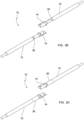
- Figure 1 shows a perspective view of the down conductor connection system 10.
- the down conductor connection system 10 is illustrated fully assembled, though without illustrating the clamp.
- the illustrated down conductor connection system 10 comprises two down conductor cable parts 12 being mutual interconnected at one end, and being illustrated with an opposite free end, which in the illustrated embodiment is uninsulated.
- the uninsulated end parts 30 (not shown) of the down conductor cable parts 12 are arranged for being connected to another opposed down conductor cable part via another down conductor connection system 10 or suitable for being connected to a lightning receptor.
- the down conductor cables 12 are shown interconnected via the first and second outer protective insulation covers 26, 28, fully enclosing the internal interconnected terminals 14 (not shown). Further, insulation layers 22 are shown extending from an inside of the connection system to and outside, and partly overlapping an outer surface of the down conductor cable parts. In a preferred alternative embodiment, the first and second outer protective insulation covers 26, 28 also enclose the ends of the insulation layers.
- the connection between the first and second outer protective insulation covers 26, 28 is in the figure established by an integrated locking mechanism 38 illustrated as a bayonet lock.
- the outer protective insulation covers 26,28 may alternatively be fabricated without the integrated locking mechanism 38, and thus, the mutual interconnection between the two protective insulation covers 26, 28 may be accomplished by other suitable locking means, such as a screw mechanism, an external mechanical locking element, or a semi-conductive tape wrapped around the abutting outer protective insulation covers 26, 28.
- FIGS 2A - 2D show perspective views of the down conductor connection system 10 in partly assembled states. The figures illustrate parts of the down conductor connection system 10 before the down conductor parts 12 are interconnected.
- FIG. 2A illustrates the connection of the terminals 14 on uninsulated end parts 30 of the down conductor cable parts 12.
- Each terminal 14 comprises a first end for connection to the opposed terminal 14, and a second end comprising a opening for receiving the uninsulated end part 30 of the down conductor cable part 12.
- the ends of the down conductor parts are preferable connected to the open ends of the terminals 14 by crimping process or e.g. by welding.
- Figure 2B illustrates the terminals 14 being arranged on ends of the down conductor cable parts 12, and illustrates a remaining part of the uninsulated end part 30 still exposed between the terminals 14 and the insulated cable part 12.
- This exposed uninsulated end part 30 may vary according to production tolerances, however, as little as possible of the remaining exposed uninsulated end part 30 is requested.
- Figure 2C illustrates the semi-conductive layers 20 being arranged over the transition regions of the insulated down conductor cable parts 12 and the terminals 14.
- the semi-conductive layers 20 partly overlap the terminals 14, fully cover any exposed uninsulated end part 30, and preferable overlaps a part of the insulated down conductor cable parts 12 as well.
- the semi-conductive layers 20 do not overlap the insulated cable parts 12, but only span the uninsulated cable parts 30, and partly the terminals 14.
- Figure 2D illustrates the additional insulation layers 22 arranged on top of, and enclosing the semi-conductive layers 20.
- the insulation layers 22 only partly enclose the semi-conductive layers 20.
- the insulation layers 22 preferably overlap part of the insulated down conductor cable part 12, hereby arranging the transition between the down conductor cable parts 12 end the terminals 14 in enhanced electrical insulation.
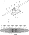
- Figures 3A - 3B show perspective views of the down conductor connection system being assembled.
- FIG 3A illustrates a possible connection between the two opposed terminals 14.
- Each of the terminals 14 may comprise a number of apertures (shown as two apertures), where each aperture aligns with a corresponding aperture of the opposed terminal 14, such that when the two terminals 14 are correctly arranged in relation to each other, locking means 18, 19, such as bolts 18, may arranged through the apertures and secured in place by a cooperating nut 19.
- the illustrated embodiment of the locking elements 18, 19 being bolts 18 and nuts 19 just illustrates only one of several possible embodiments of interconnecting the two terminals.
- Other suitable embodiments include screws, locking pawls, glue, or a further alternative embodiment where the connecting surfaces of each terminal 14 comprise projecting elements that interlock with the projecting element of the opposed terminal 14.
- Figure 3B illustrates the two terminals 14 being connected, and illustrates the pre-manufactured semi-conductive insert 24 being ready for insertion around the connected terminals 14.
- the pre-manufactured semi-conductive insert 24 is illustrated as a tubular element having a through-going longitudinal slit, such that the pre-manufactured semi-conductive insert 24 may be wrapped around the interconnected terminals 14.
- Figure 4 shows a perspective view of the assembling of the outer protective insulation covers 26, 28.
- the figure illustrates a possible final step in interconnecting the opposed down conductor cable parts 12.
- the pre-manufactured semi-conductive insert 24 is shown arranged over the interconnected terminals 14 (not shown).
- An end seal 32 and a first or second outer protection insulation cover are arranged on each side of the pre-manufactured semi-conductive insert 24.
- each end seal 32 is moved into abutment with the stepped contour of the insulation layer 22, and the first and second outer protective insulation covers 26, 28 are moved into mutual interlocked connection, whereby the pre-manufactured semi-conductive insert 24 is fully enclosed.
- Fig. 5 shows a perspective view of the down conductor connection system 10 being arranged in a clamp 34.
- the down conductor connection system 10 is illustrated in a position where the connection system 10 is being arranged in the clamp 34.
- the clamp 34 is in this embodiment arranged with a flat base portion for connecting to an inner part of the wind turbine blade via suitable connection means.
- the base portion comprises a number of projecting elements 36 for clamping around portions of the first and second outer protection insulation covers 26, 28.
- the clamp 34 may comprise a suitable number of clamping elements 36 for clamping the protective insulation covers 26, 28 and/or the down conductor cable parts 12. Alternatively, the clamp 34 may be integrated with one of the protective insulation covers.
- Fig. 6 shows a cross section of the down conductor connection system and clearly illustrates the mutual relationship between the individual elements. The illustration is just a basic, possible embodiment, and thus the arrangement of the individual parts may vary.
- Fig. 7 shows a perspective view of a wind turbine with a wind turbine blade having a lightning protection system comprising a down conductor connection system.
- the figure is a schematic illustration of a possible embodiment of a wind turbine blade having a down conductor 40 extending in the longitudinal direction of the wind turbine blade from the tip end to the root end 46.
- the lightning protection system comprises a tip receptor 42 arranged at an end of the down conductor 40, and a number of side receptors 44 electrically connected to and distributed along the length of the down conductor 40.
- the embodiment shown in the figure illustrates the lightning protection system having two down conductor connection systems 10; however, any further number, or just one connection system 10 may be employed into the lightning protection system.
Landscapes
- Engineering & Computer Science (AREA)
- Life Sciences & Earth Sciences (AREA)
- Sustainable Development (AREA)
- Sustainable Energy (AREA)
- Chemical & Material Sciences (AREA)
- Combustion & Propulsion (AREA)
- Mechanical Engineering (AREA)
- General Engineering & Computer Science (AREA)
- Wind Motors (AREA)
- Cable Accessories (AREA)
- Details Of Connecting Devices For Male And Female Coupling (AREA)
Claims (14)
- Ableiteranschlusssystem (10) für ein Blitzschutzsystem, das dazu angepasst ist, eine Windturbinenschaufel vor Blitzeinschlägen zu schützen, wobei das Blitzschutzsystem ein Ableiterkabel, das dazu angepasst ist, sich in einer Längsrichtung der Windturbinenschaufel zu erstrecken, und an das Fußende der Windturbinenschaufel angeschlossen ist, und eine Anzahl von Blitzrezeptoren, die elektrisch an das Ableiterkabel angeschlossen und entlang dessen Länge verteilt sind, aufweist,wobei das Ableitersystem ein modulares Ableiterkabel, das einen ersten und einen zweiten Ableiterkabelteil (12) aufweist, und mindestens einen Ableiteranschließer, der zwischen Enden des ersten und des zweiten Ableiterkabelteils angeordnet und an diese angeschlossen ist, aufweist,wobei der Ableiteranschließer einen ersten Abschluss, der an ein Ende eines ersten Ableiterkabelteils angeschlossen ist, und einen zweiten Abschluss, der an ein Ende eines zweiten Ableiterkabelteils angeschlossen ist, aufweist,wobei der erste und der zweite Abschluss zu einem gegenseitigen Anschluss derart angepasst sind, dass, wenn sie angeschlossen sind, der erste und der zweite Ableiterkabelteil mindestens teilweise das modulare Ableiterkabel definieren, wobei der Ableiteranschließer Halbleiterschichten (20) umfasst, wobei jede um ein jeweiliges erstes Ende des ersten bzw. des zweiten Abschlusses und die Enden des ersten bzw. des zweiten Ableiterkabelteils (12) angeordnet ist und dadurch den ersten und den zweiten Abschluss und jeden unisolierten Endteil der Ableiterkabelteile teilweise umschließt.
- Ableiteranschlusssystem (10) nach Anspruch 1, wobei der erste und der zweite Abschluss (14) mit dem ersten Ende an das Ende des ersten bzw. des zweiten Ableiterkabelteils angeschlossen sind und ein zweites Ende eine Anschlussfläche aufweist, die sich zum gegenseitigen Anschließen der Abschlüsse (14) aneinander im Wesentlichen in einer Längsrichtung des modularen Ableiterkabels erstreckt.
- Ableiteranschlusssystem (10) nach Anspruch 2, wobei der erste und der zweite Abschluss (14) lösliche Verriegelungsmittel (18, 19) zum Befestigen der Anschlussflächen in einem gegenseitig verriegelten Anschluss aufweisen.
- Ableiteranschlusssystem (10) nach einem der Ansprüche 1-3, wobei der Ableiteranschluss Isolationsschichten (22) umfasst, wobei jede um jede der Halbleiterschichten angeordnet ist und sie derart umschließt, dass der Anschluss zwischen den Abschlüssen und den Ableiterkabelteilen isoliert ist.
- Ableiteranschlusssystem (10) nach einem der Ansprüche 1-4, wobei der Ableiteranschluss einen vorgefertigten Halbleitereinsatz (24) umfasst, der um die aneinander angeschlossenen Abschlüsse zwischen den Halbleiterschichten (20) angeordnet ist.
- Ableiteranschlusssystem (10) nach einem der Ansprüche 1-5, wobei der Ableiteranschließer Folgendes umfasst:eine erste äußere Schutzisolationsabdeckung (26), die an den ersten Ableiterkabelteil angeschlossen ist und ihn umgibt, wobei die erste äußere Schutzisolationsabdeckung zum mindestens teilweisen Umschließen des vorgefertigten Halbleitereinsatzes (24) angeordnet ist;eine zweite äußere Schutzisolationsabdeckung (28), die an den zweiten Ableiterkabelteil angeschlossen ist und ihn umgibt, wobei die zweite äußere Schutzabdeckung zum mindestens teilweisen Umschließen des vorgefertigten Halbleitereinsatzes (24) und Zusammenpassen mit der ersten äußeren Schutzisolationsabdeckung (26) angeordnet ist.
- Ableiteranschlusssystem (10) nach Anspruch 6, wobei sich die zweite äußere Schutzisolationsabdeckung (28) teilweise mit der ersten äußeren Schutzisolationsabdeckung (26) überlappt,
wobei die erste und die zweite äußere Schutzisolationsabdeckung (26, 28) gegenseitige Verriegelungsmittel aufweisen, die zum Verriegeln der äußeren Schutzabdeckungen miteinander und dadurch sämtlichen Umschließen der Abschlüsse (14) und des vorgefertigten Halbleitereinsatzes (24) angeordnet sind. - Ableiteranschlusssystem (10) nach Anspruch 6 oder 7, wobei eine äußere Fläche der Isolationsschichten einen gestuften Umriss, der einem inneren gestuften Umriss der äußeren Schutzabdeckungen entspricht, derart umfasst, dass eine Bewegung der äußeren Schutzabdeckungen auf jedem Ableiterkabelteil in einer Richtung der Anschließerteile beschränkt ist.
- Ableiteranschlusssystem (10) nach einem der Ansprüche 6-8, wobei das Anschlusssystem eine gleitbare Endabdichtung (32), wie etwa einen Abdichtungsring, zum Anordnen der äußeren Schutzabdeckungen in einem wasserdichten Anschluss an die Kabelteile aufweist, wobei die Endabdichtung auf jedem der Enden der Ableiterkabelteile angeordnet und zwischen den Kabeln und der ersten bzw. der zweiten äußeren Schutzabdeckung angebracht ist.
- Ableiteranschlusssystem (10) nach einem der Ansprüche 6-9, wobei das Anschlusssystem eine Klemme (34) zum Befestigen des Anschlusssystems gegenüber der Windturbinenschaufel umfasst,
wobei das Klemmelement eine Verbindungsfläche zum Verbinden gegenüber einem Teil einer besagten Windturbinenschaufel und eine Anzahl von Klemmelementen (36) zum mindestens teilweisen Umschließen der äußeren Schutzabdeckungen und Klemmen des Anschlusssystems gegenüber der Windturbinenschaufel aufweist. - Blitzschutzsystem, das dazu angepasst ist, eine Windturbinenschaufel vor Blitzeinschlägen zu schützen, wobei das Schutzsystem ein Ableiterkabel, das dazu angepasst ist, sich in der Längsrichtung der Windturbinenschaufel zu erstrecken und an das Fußende der Windturbinenschaufel angeschlossen ist, beinhaltet, wobei das Blitzschutzsystem eine Anzahl von Blitzrezeptoren aufweist, die elektrisch an das Ableiterkabel angeschlossen und entlang dessen Länge verteilt sind, wobei das Ableiterkabel ein modulares Ableiterkabel ist, das ein Ableiteranschlusssystem (10) nach einem der Ansprüche 1-10 aufweist.
- Verfahren zum Anordnen eines Ableiteranschlusssystems nach einem der Ansprüche 5-11 in einem Blitzschutzsystem nach Anspruch 11, wobei das Verfahren die folgenden Schritte umfasst:• Bereitstellen einer Anzahl von Abschlüssen,• Bereitstellen einer Anzahl von Ableiterkabelteilen,• jeweiliges Anschließen eines ersten Endes der Abschlüsse an ein Ende der Ableiterkabelteile,• jeweiliges Anordnen einer Halbleiterschicht um das erste Ende der Abschlüsse und das Ende der Kabelteile,• Anordnen der Anzahl von Ableiterkabelteilen, von denen jeder einen Abschluss aufweist, innerhalb der Windturbinenschaufel in einer Längsrichtung davon und• aneinander Anschließen mindestens zweier benachbarter Kabelteile durch Anschließen zweiter Enden der Abschlüsse.
- Verfahren nach Anspruch 12, ferner umfassend:
derartiges Anordnen einer Isolationsschicht um die Halbleiterschichten, dass der Anschluss zwischen den Abschlüssen und den Ableiterkabelteilen isoliert ist. - Verfahren nach einem der Ansprüche 12-13, ferner umfassend:
Anordnen eines vorgefertigten Halbleitereinsatzes um die angeschlossenen Abschlüsse zwischen den Halbleiterschichten oder den Isolationsschichten.
Applications Claiming Priority (1)
| Application Number | Priority Date | Filing Date | Title |
|---|---|---|---|
| PCT/IB2018/057359 WO2020065368A1 (en) | 2018-09-24 | 2018-09-24 | Down conductor connection system, wind turbine lightning protection system, and method for arranging a down conductor connection system |
Publications (2)
| Publication Number | Publication Date |
|---|---|
| EP3857063A1 EP3857063A1 (de) | 2021-08-04 |
| EP3857063B1 true EP3857063B1 (de) | 2025-06-18 |
Family
ID=63794576
Family Applications (1)
| Application Number | Title | Priority Date | Filing Date |
|---|---|---|---|
| EP18783135.9A Active EP3857063B1 (de) | 2018-09-24 | 2018-09-24 | Ableiteranschlusssystem, blitzschutzsystem für windturbinen und verfahren zur anordnung eines ableiteranschlusssystems |
Country Status (6)
| Country | Link |
|---|---|
| US (1) | US11536252B2 (de) |
| EP (1) | EP3857063B1 (de) |
| CN (1) | CN112739909B (de) |
| DK (1) | DK3857063T3 (de) |
| ES (1) | ES3039346T3 (de) |
| WO (1) | WO2020065368A1 (de) |
Families Citing this family (4)
| Publication number | Priority date | Publication date | Assignee | Title |
|---|---|---|---|---|
| EP3628863B1 (de) * | 2018-09-26 | 2022-11-09 | Siemens Gamesa Renewable Energy A/S | Blitzschutz für einen rotorblattaufsatz |
| CN113833616B (zh) * | 2021-09-14 | 2023-03-24 | 洛阳双瑞风电叶片有限公司 | 一种风电叶片防雷系统 |
| EP4592524A4 (de) * | 2022-09-20 | 2025-11-12 | Nabrawind Tech S L | Blitzschutzvorrichtung in einer modularen schaufel |
| CN117895280B (zh) * | 2024-03-18 | 2024-06-11 | 绵阳华岩电子有限公司 | 一种高强度连接及可靠屏蔽的互耦连接器 |
Citations (2)
| Publication number | Priority date | Publication date | Assignee | Title |
|---|---|---|---|---|
| EP3340390A1 (de) * | 2016-12-21 | 2018-06-27 | Nordex Energy GmbH | Kabelverbinder für hochstrom |
| US20180274521A1 (en) * | 2017-03-22 | 2018-09-27 | General Electric Company | Method for Securing a Lightning Receptor Cable Within a Segmented Rotor Blade |
Family Cites Families (27)
| Publication number | Priority date | Publication date | Assignee | Title |
|---|---|---|---|---|
| DE29522152U1 (de) * | 1994-09-07 | 2000-03-02 | Bonus Energy A/S, Brande | Blitzableiteranordnung für ein Windradblatt |
| JP4695958B2 (ja) * | 2005-10-13 | 2011-06-08 | 東京電力株式会社 | 電力ケーブル用接続部 |
| EP1961082B1 (de) * | 2005-12-12 | 2009-08-26 | Vestas Wind Systems A/S | Windturbine, hochstromverbinder und verwendungen dafür |
| ES2657089T3 (es) * | 2006-05-24 | 2018-03-01 | Vestas Wind Systems A/S | Un sistema de puesta a tierra para una turbina eólica conectada a una red de distribución y para un parque eólico |
| GB2469520A (en) | 2009-04-17 | 2010-10-20 | Tyco Electronics Ltd Uk | Wind Turbine Lightning Protection And Monitoring Systems |
| CN102652221B (zh) | 2009-12-09 | 2016-10-12 | 西门子公司 | 用于风力涡轮机的防雷系统和具有防雷系统的风力涡轮机 |
| EP2510582B1 (de) * | 2009-12-10 | 2018-02-21 | Prysmian S.p.A. | Erdverbindung |
| GB201013723D0 (en) | 2010-08-17 | 2010-09-29 | Rolls Royce Plc | Manifold mounting arrangement |
| US7988415B2 (en) * | 2010-08-31 | 2011-08-02 | General Electric Company | Lightning protection for wind turbines |
| DE102010045921A1 (de) * | 2010-09-21 | 2012-03-22 | Auto-Kabel Managementgesellschaft Mbh | Elektrisches Verbindungssystem einer Energiegewinnungseinrichtung |
| US20110142671A1 (en) * | 2010-12-01 | 2011-06-16 | General Electric Company | Wind turbine rotor blades with enhanced lightning protection system |
| CN202326040U (zh) * | 2011-11-18 | 2012-07-11 | 广东东兴风盈风电设备制造有限公司 | 一种风力发电机风轮 |
| US20190195203A1 (en) * | 2011-12-09 | 2019-06-27 | Mitsubishi Heavy Industries, Ltd. | Wind turbine blade for a wind turbine |
| CN103174603A (zh) * | 2011-12-23 | 2013-06-26 | 新疆金风科技股份有限公司 | 一种风力发电机组防雷装置及风力发电机组 |
| DE102012010277A1 (de) * | 2012-05-25 | 2013-11-28 | Auto-Kabel Management Gmbh | Elektrisches Verbindungssystem |
| US10427363B2 (en) * | 2013-02-13 | 2019-10-01 | Vestas Wind Systems A/S | Wind turbine blade having a lightning protection system and method of making the same |
| PL3004638T3 (pl) * | 2013-05-24 | 2017-09-29 | Lm Wp Patent Holding A/S | System ochrony odgromowej dla łopaty turbiny wiatrowej |
| GB2519332A (en) * | 2013-10-17 | 2015-04-22 | Vestas Wind Sys As | Improvements relating to lightning protection systems for wind turbine blades |
| KR20170086071A (ko) * | 2014-11-14 | 2017-07-25 | 글로벌 라이트닝 프로텍션 서비시즈 에이/에스 | 풍력 터빈 블레이드용 피뢰 시스템을 위한 완전 절연 팁 유닛 및 이를 포함하는 풍력 터빈 블레이드 |
| KR101615905B1 (ko) * | 2014-11-28 | 2016-04-27 | 대우조선해양 주식회사 | 풍력 발전기의 낙뢰전류 이송장치 및 그가 적용되는 낙뢰보호장치 |
| US9719495B2 (en) * | 2015-05-13 | 2017-08-01 | General Electric Company | Lightning protection system for wind turbine rotor blades |
| JP6532816B2 (ja) * | 2015-11-27 | 2019-06-19 | 日本特殊陶業株式会社 | 端子を備えた部材及びその製造方法 |
| ES2646015B1 (es) * | 2016-06-07 | 2018-09-20 | Gamesa Innovation & Technology, S.L. | Sistema pararrayos para palas de aerogeneradores con medios optimizados de inyección de corrientes de rayo en los componentes conductores de sus conchas. |
| DE102016116144A1 (de) * | 2016-08-30 | 2018-03-01 | Nordex Energy Gmbh | Blitzschutzeinrichtung für ein Windenergieanlagenrotorblatt |
| CN106848764A (zh) * | 2017-02-09 | 2017-06-13 | 广州供电局有限公司 | 母端电缆连接器、公端电缆连接器及电缆连接器组件 |
| US11319933B2 (en) * | 2017-09-12 | 2022-05-03 | Vestas Wind Systems A/S | Rotor blade for a wind turbine incorporating a lightning protection system |
| CN107642463B (zh) * | 2017-09-15 | 2019-05-03 | 宁夏中科天际防雷股份有限公司 | 一种发电设备雷电防护装置 |
-
2018
- 2018-09-24 EP EP18783135.9A patent/EP3857063B1/de active Active
- 2018-09-24 WO PCT/IB2018/057359 patent/WO2020065368A1/en not_active Ceased
- 2018-09-24 DK DK18783135.9T patent/DK3857063T3/da active
- 2018-09-24 CN CN201880097463.0A patent/CN112739909B/zh active Active
- 2018-09-24 US US17/278,950 patent/US11536252B2/en active Active
- 2018-09-24 ES ES18783135T patent/ES3039346T3/es active Active
Patent Citations (2)
| Publication number | Priority date | Publication date | Assignee | Title |
|---|---|---|---|---|
| EP3340390A1 (de) * | 2016-12-21 | 2018-06-27 | Nordex Energy GmbH | Kabelverbinder für hochstrom |
| US20180274521A1 (en) * | 2017-03-22 | 2018-09-27 | General Electric Company | Method for Securing a Lightning Receptor Cable Within a Segmented Rotor Blade |
Also Published As
| Publication number | Publication date |
|---|---|
| EP3857063A1 (de) | 2021-08-04 |
| ES3039346T3 (en) | 2025-10-20 |
| CN112739909A (zh) | 2021-04-30 |
| US11536252B2 (en) | 2022-12-27 |
| US20220034306A1 (en) | 2022-02-03 |
| BR112021004388A2 (pt) | 2021-07-20 |
| CN112739909B (zh) | 2024-02-06 |
| DK3857063T3 (da) | 2025-06-30 |
| WO2020065368A1 (en) | 2020-04-02 |
Similar Documents
| Publication | Publication Date | Title |
|---|---|---|
| EP3857063B1 (de) | Ableiteranschlusssystem, blitzschutzsystem für windturbinen und verfahren zur anordnung eines ableiteranschlusssystems | |
| US10355470B2 (en) | Cable fitting for connecting a high-voltage cable to a high-voltage component | |
| US6452102B1 (en) | High voltage cable termination | |
| US20110151707A1 (en) | A connector with a connecting member with a screw portion penetrating the insulators and terminals of two mating terminal housings | |
| US10027071B2 (en) | Cable connection device | |
| CN101262109A (zh) | 带有聚合弹簧夹螺母的环形波纹状同轴电缆连接器 | |
| GB2109172A (en) | Cable jointing connection | |
| US20190296538A1 (en) | Underwater electrical connection system | |
| CN102859808A (zh) | 引线框以及具备引线框的连接插座 | |
| GB2116381A (en) | High voltage electrical connector | |
| EP3174165B1 (de) | Kabelverbinder | |
| CN1306328A (zh) | 充有绝缘气体的封闭式配电盘间用的母线连接装置 | |
| US8308508B2 (en) | Connector | |
| US20140209345A1 (en) | Power Connector for an Electrical Motor | |
| US12463387B2 (en) | Housing for housing a conductor connecting flat conductor rail to a connecting connector, a system including said housing, and method for manufacturing the system | |
| US20130306345A1 (en) | Dead front cable terminal with isolated shield | |
| US9762046B2 (en) | Sleeve for shielding electrical joint | |
| WO1991011040A1 (en) | Cable connector | |
| US20240405537A1 (en) | Termination for a cable for transporting high-voltage or very-high-voltage electricity, and method for preparing a cable end termination | |
| US20220375653A1 (en) | Ground shield bridge | |
| JP3181504B2 (ja) | 電力ケーブル接続部 | |
| EP3934039A1 (de) | Leiterverbinder und kabelverbindungssystem | |
| JP7831209B2 (ja) | ケーブル接続構造体 | |
| US20240429686A1 (en) | Electrical busway assemblies and methods of assembling same | |
| US20250260184A1 (en) | Reversible Splice Connector |
Legal Events
| Date | Code | Title | Description |
|---|---|---|---|
| STAA | Information on the status of an ep patent application or granted ep patent |
Free format text: STATUS: UNKNOWN |
|
| STAA | Information on the status of an ep patent application or granted ep patent |
Free format text: STATUS: THE INTERNATIONAL PUBLICATION HAS BEEN MADE |
|
| PUAI | Public reference made under article 153(3) epc to a published international application that has entered the european phase |
Free format text: ORIGINAL CODE: 0009012 |
|
| STAA | Information on the status of an ep patent application or granted ep patent |
Free format text: STATUS: REQUEST FOR EXAMINATION WAS MADE |
|
| 17P | Request for examination filed |
Effective date: 20210414 |
|
| AK | Designated contracting states |
Kind code of ref document: A1 Designated state(s): AL AT BE BG CH CY CZ DE DK EE ES FI FR GB GR HR HU IE IS IT LI LT LU LV MC MK MT NL NO PL PT RO RS SE SI SK SM TR |
|
| DAV | Request for validation of the european patent (deleted) | ||
| DAX | Request for extension of the european patent (deleted) | ||
| STAA | Information on the status of an ep patent application or granted ep patent |
Free format text: STATUS: EXAMINATION IS IN PROGRESS |
|
| 17Q | First examination report despatched |
Effective date: 20240202 |
|
| GRAP | Despatch of communication of intention to grant a patent |
Free format text: ORIGINAL CODE: EPIDOSNIGR1 |
|
| STAA | Information on the status of an ep patent application or granted ep patent |
Free format text: STATUS: GRANT OF PATENT IS INTENDED |
|
| INTG | Intention to grant announced |
Effective date: 20240925 |
|
| GRAS | Grant fee paid |
Free format text: ORIGINAL CODE: EPIDOSNIGR3 |
|
| GRAJ | Information related to disapproval of communication of intention to grant by the applicant or resumption of examination proceedings by the epo deleted |
Free format text: ORIGINAL CODE: EPIDOSDIGR1 |
|
| GRAL | Information related to payment of fee for publishing/printing deleted |
Free format text: ORIGINAL CODE: EPIDOSDIGR3 |
|
| STAA | Information on the status of an ep patent application or granted ep patent |
Free format text: STATUS: EXAMINATION IS IN PROGRESS |
|
| GRAP | Despatch of communication of intention to grant a patent |
Free format text: ORIGINAL CODE: EPIDOSNIGR1 |
|
| STAA | Information on the status of an ep patent application or granted ep patent |
Free format text: STATUS: GRANT OF PATENT IS INTENDED |
|
| INTC | Intention to grant announced (deleted) | ||
| P01 | Opt-out of the competence of the unified patent court (upc) registered |
Free format text: CASE NUMBER: APP_1966/2025 Effective date: 20250113 |
|
| RAP3 | Party data changed (applicant data changed or rights of an application transferred) |
Owner name: POLYTECH A/S |
|
| INTG | Intention to grant announced |
Effective date: 20250130 |
|
| GRAA | (expected) grant |
Free format text: ORIGINAL CODE: 0009210 |
|
| STAA | Information on the status of an ep patent application or granted ep patent |
Free format text: STATUS: THE PATENT HAS BEEN GRANTED |
|
| AK | Designated contracting states |
Kind code of ref document: B1 Designated state(s): AL AT BE BG CH CY CZ DE DK EE ES FI FR GB GR HR HU IE IS IT LI LT LU LV MC MK MT NL NO PL PT RO RS SE SI SK SM TR |
|
| REG | Reference to a national code |
Ref country code: GB Ref legal event code: FG4D |
|
| REG | Reference to a national code |
Ref country code: DK Ref legal event code: T3 Effective date: 20250626 Ref country code: CH Ref legal event code: EP |
|
| REG | Reference to a national code |
Ref country code: DE Ref legal event code: R096 Ref document number: 602018082693 Country of ref document: DE |
|
| REG | Reference to a national code |
Ref country code: CH Ref legal event code: EP |
|
| REG | Reference to a national code |
Ref country code: IE Ref legal event code: FG4D |
|
| PG25 | Lapsed in a contracting state [announced via postgrant information from national office to epo] |
Ref country code: FI Free format text: LAPSE BECAUSE OF FAILURE TO SUBMIT A TRANSLATION OF THE DESCRIPTION OR TO PAY THE FEE WITHIN THE PRESCRIBED TIME-LIMIT Effective date: 20250618 |
|
| PGFP | Annual fee paid to national office [announced via postgrant information from national office to epo] |
Ref country code: DK Payment date: 20250721 Year of fee payment: 8 Ref country code: DE Payment date: 20250821 Year of fee payment: 8 |
|
| REG | Reference to a national code |
Ref country code: LT Ref legal event code: MG9D |
|
| PG25 | Lapsed in a contracting state [announced via postgrant information from national office to epo] |
Ref country code: NO Free format text: LAPSE BECAUSE OF FAILURE TO SUBMIT A TRANSLATION OF THE DESCRIPTION OR TO PAY THE FEE WITHIN THE PRESCRIBED TIME-LIMIT Effective date: 20250918 Ref country code: GR Free format text: LAPSE BECAUSE OF FAILURE TO SUBMIT A TRANSLATION OF THE DESCRIPTION OR TO PAY THE FEE WITHIN THE PRESCRIBED TIME-LIMIT Effective date: 20250919 |
|
| PG25 | Lapsed in a contracting state [announced via postgrant information from national office to epo] |
Ref country code: BG Free format text: LAPSE BECAUSE OF FAILURE TO SUBMIT A TRANSLATION OF THE DESCRIPTION OR TO PAY THE FEE WITHIN THE PRESCRIBED TIME-LIMIT Effective date: 20250618 |
|
| PGFP | Annual fee paid to national office [announced via postgrant information from national office to epo] |
Ref country code: GB Payment date: 20250718 Year of fee payment: 8 |
|
| PG25 | Lapsed in a contracting state [announced via postgrant information from national office to epo] |
Ref country code: HR Free format text: LAPSE BECAUSE OF FAILURE TO SUBMIT A TRANSLATION OF THE DESCRIPTION OR TO PAY THE FEE WITHIN THE PRESCRIBED TIME-LIMIT Effective date: 20250618 |
|
| REG | Reference to a national code |
Ref country code: ES Ref legal event code: FG2A Ref document number: 3039346 Country of ref document: ES Kind code of ref document: T3 Effective date: 20251020 |
|
| PG25 | Lapsed in a contracting state [announced via postgrant information from national office to epo] |
Ref country code: RS Free format text: LAPSE BECAUSE OF FAILURE TO SUBMIT A TRANSLATION OF THE DESCRIPTION OR TO PAY THE FEE WITHIN THE PRESCRIBED TIME-LIMIT Effective date: 20250918 |
|
| REG | Reference to a national code |
Ref country code: NL Ref legal event code: MP Effective date: 20250618 |
|
| PG25 | Lapsed in a contracting state [announced via postgrant information from national office to epo] |
Ref country code: LV Free format text: LAPSE BECAUSE OF FAILURE TO SUBMIT A TRANSLATION OF THE DESCRIPTION OR TO PAY THE FEE WITHIN THE PRESCRIBED TIME-LIMIT Effective date: 20250618 |
|
| PG25 | Lapsed in a contracting state [announced via postgrant information from national office to epo] |
Ref country code: NL Free format text: LAPSE BECAUSE OF FAILURE TO SUBMIT A TRANSLATION OF THE DESCRIPTION OR TO PAY THE FEE WITHIN THE PRESCRIBED TIME-LIMIT Effective date: 20250618 |
|
| PG25 | Lapsed in a contracting state [announced via postgrant information from national office to epo] |
Ref country code: PT Free format text: LAPSE BECAUSE OF FAILURE TO SUBMIT A TRANSLATION OF THE DESCRIPTION OR TO PAY THE FEE WITHIN THE PRESCRIBED TIME-LIMIT Effective date: 20251020 |
|
| REG | Reference to a national code |
Ref country code: AT Ref legal event code: MK05 Ref document number: 1804380 Country of ref document: AT Kind code of ref document: T Effective date: 20250618 |
|
| PG25 | Lapsed in a contracting state [announced via postgrant information from national office to epo] |
Ref country code: IS Free format text: LAPSE BECAUSE OF FAILURE TO SUBMIT A TRANSLATION OF THE DESCRIPTION OR TO PAY THE FEE WITHIN THE PRESCRIBED TIME-LIMIT Effective date: 20251018 |
|
| PG25 | Lapsed in a contracting state [announced via postgrant information from national office to epo] |
Ref country code: AT Free format text: LAPSE BECAUSE OF FAILURE TO SUBMIT A TRANSLATION OF THE DESCRIPTION OR TO PAY THE FEE WITHIN THE PRESCRIBED TIME-LIMIT Effective date: 20250618 Ref country code: SM Free format text: LAPSE BECAUSE OF FAILURE TO SUBMIT A TRANSLATION OF THE DESCRIPTION OR TO PAY THE FEE WITHIN THE PRESCRIBED TIME-LIMIT Effective date: 20250618 |
|
| PG25 | Lapsed in a contracting state [announced via postgrant information from national office to epo] |
Ref country code: CZ Free format text: LAPSE BECAUSE OF FAILURE TO SUBMIT A TRANSLATION OF THE DESCRIPTION OR TO PAY THE FEE WITHIN THE PRESCRIBED TIME-LIMIT Effective date: 20250618 |
|
| PG25 | Lapsed in a contracting state [announced via postgrant information from national office to epo] |
Ref country code: PL Free format text: LAPSE BECAUSE OF FAILURE TO SUBMIT A TRANSLATION OF THE DESCRIPTION OR TO PAY THE FEE WITHIN THE PRESCRIBED TIME-LIMIT Effective date: 20250618 |
|
| PG25 | Lapsed in a contracting state [announced via postgrant information from national office to epo] |
Ref country code: EE Free format text: LAPSE BECAUSE OF FAILURE TO SUBMIT A TRANSLATION OF THE DESCRIPTION OR TO PAY THE FEE WITHIN THE PRESCRIBED TIME-LIMIT Effective date: 20250618 |
|
| PG25 | Lapsed in a contracting state [announced via postgrant information from national office to epo] |
Ref country code: SK Free format text: LAPSE BECAUSE OF FAILURE TO SUBMIT A TRANSLATION OF THE DESCRIPTION OR TO PAY THE FEE WITHIN THE PRESCRIBED TIME-LIMIT Effective date: 20250618 Ref country code: RO Free format text: LAPSE BECAUSE OF FAILURE TO SUBMIT A TRANSLATION OF THE DESCRIPTION OR TO PAY THE FEE WITHIN THE PRESCRIBED TIME-LIMIT Effective date: 20250618 |
|
| PGFP | Annual fee paid to national office [announced via postgrant information from national office to epo] |
Ref country code: ES Payment date: 20251126 Year of fee payment: 8 |
|
| PG25 | Lapsed in a contracting state [announced via postgrant information from national office to epo] |
Ref country code: IT Free format text: LAPSE BECAUSE OF FAILURE TO SUBMIT A TRANSLATION OF THE DESCRIPTION OR TO PAY THE FEE WITHIN THE PRESCRIBED TIME-LIMIT Effective date: 20250618 |
|
| PLBE | No opposition filed within time limit |
Free format text: ORIGINAL CODE: 0009261 |
|
| STAA | Information on the status of an ep patent application or granted ep patent |
Free format text: STATUS: NO OPPOSITION FILED WITHIN TIME LIMIT |