EP3856504B1 - Transfer ring with block and rail system - Google Patents
Transfer ring with block and rail system Download PDFInfo
- Publication number
- EP3856504B1 EP3856504B1 EP19864397.5A EP19864397A EP3856504B1 EP 3856504 B1 EP3856504 B1 EP 3856504B1 EP 19864397 A EP19864397 A EP 19864397A EP 3856504 B1 EP3856504 B1 EP 3856504B1
- Authority
- EP
- European Patent Office
- Prior art keywords
- transfer ring
- coupled
- circular frame
- shoes
- pivotably coupled
- Prior art date
- Legal status (The legal status is an assumption and is not a legal conclusion. Google has not performed a legal analysis and makes no representation as to the accuracy of the status listed.)
- Active
Links
Images



Classifications
-
- B—PERFORMING OPERATIONS; TRANSPORTING
- B29—WORKING OF PLASTICS; WORKING OF SUBSTANCES IN A PLASTIC STATE IN GENERAL
- B29D—PRODUCING PARTICULAR ARTICLES FROM PLASTICS OR FROM SUBSTANCES IN A PLASTIC STATE
- B29D30/00—Producing pneumatic or solid tyres or parts thereof
- B29D30/06—Pneumatic tyres or parts thereof (e.g. produced by casting, moulding, compression moulding, injection moulding, centrifugal casting)
- B29D30/08—Building tyres
- B29D30/20—Building tyres by the flat-tyre method, i.e. building on cylindrical drums
- B29D30/24—Drums
- B29D30/26—Accessories or details, e.g. membranes, transfer rings
- B29D30/2607—Devices for transferring annular tyre components during the building-up stage, e.g. from the first stage to the second stage building drum
-
- B—PERFORMING OPERATIONS; TRANSPORTING
- B29—WORKING OF PLASTICS; WORKING OF SUBSTANCES IN A PLASTIC STATE IN GENERAL
- B29D—PRODUCING PARTICULAR ARTICLES FROM PLASTICS OR FROM SUBSTANCES IN A PLASTIC STATE
- B29D30/00—Producing pneumatic or solid tyres or parts thereof
- B29D30/0016—Handling tyres or parts thereof, e.g. supplying, storing, conveying
-
- B—PERFORMING OPERATIONS; TRANSPORTING
- B29—WORKING OF PLASTICS; WORKING OF SUBSTANCES IN A PLASTIC STATE IN GENERAL
- B29D—PRODUCING PARTICULAR ARTICLES FROM PLASTICS OR FROM SUBSTANCES IN A PLASTIC STATE
- B29D30/00—Producing pneumatic or solid tyres or parts thereof
- B29D30/0016—Handling tyres or parts thereof, e.g. supplying, storing, conveying
- B29D2030/0022—Handling green tyres, e.g. transferring or storing between tyre manufacturing steps
-
- B—PERFORMING OPERATIONS; TRANSPORTING
- B29—WORKING OF PLASTICS; WORKING OF SUBSTANCES IN A PLASTIC STATE IN GENERAL
- B29D—PRODUCING PARTICULAR ARTICLES FROM PLASTICS OR FROM SUBSTANCES IN A PLASTIC STATE
- B29D30/00—Producing pneumatic or solid tyres or parts thereof
- B29D30/0016—Handling tyres or parts thereof, e.g. supplying, storing, conveying
- B29D2030/0033—Rotating tyres or their components, e.g. carcasses, belt-tread packages, beads and the like, around their axis, i.e. for preventing deformation
Definitions
- the present general inventive concept relates to devices that are useful in the manufacture of vehicle tires. More particularly, the present general inventive concept relates to an improved transfer ring useful in the manufacture of vehicle tires.
- the manufacture of a vehicle tire commonly includes the steps of forming a tire carcass, forming a toroid-shaped belt and tread "package" of the tire separately from the carcass, and thereafter marrying the belt and tread package to the tire carcass to form a "green” tire.
- the green tire is thereafter treated to form the tread and various other features of a finished tire.
- Other supplementary steps such as bonding the belt and tread package to the tire carcass (often referred to as "stitching" the belt and tread package), may be performed during the course of, or following, one or more of the aforementioned steps.
- Formation of a belt and tread package of a tire is typically accomplished using a belt and tread drum, of the type disclosed in United States Patent No. 6,013,147 .
- a belt and tread drum typically has an outer cylindrical surface, or circumference, about which one or more layers of the tire belt material (comprising, for example, reinforcement cords embedded in a polymeric binder) are laid to define the belt and tread package.
- the circumference of the belt and tread drum is preferably capable of expanding and contracting to allow, for example, removal of a completed belt and tread package from the drum.
- a completed belt and tread package is typically essentially nonexpandable radially.
- a completed belt and tread package is typically flexible to the extent that, when unsupported, the toroid-shaped belt and tread package will deform and sag under the influence of gravity.
- the adjustable circumference of the belt and tread drum enables a single drum to be used to form belt and tread packages of alternative diameters.
- a tire carcass is typically fabricated using a tire building drum, of the type described in United States Patent No. 6,457,505 .
- a tire building drum typically defines a radially expandable and contractible cylindrical working surface, similar to the above-discussed belt and tread drum, upon which a tire carcass is formed.
- an expansion drum of the type discussed in United States Patent No. 6,602,372 .
- the tire carcass is positioned surrounding the expansion drum, and a portion of the tire carcass is overlaid with the belt and tread package.
- the tire carcass is then inflated to a toroid shape resembling, though often not identical to, the shape of a finished tire. While the tire carcass is inflated, the belt and tread package is stitched to the tire carcass.
- a transfer ring typically includes a plurality of "shoe" segments having arced interior surfaces which collectively form a segmented, radially-inwardly-facing cylindrical surface suitable for grasping and holding a tire carcass and/or a belt and tread package.
- Each shoe segment is mounted on an appropriate linkage such that the shoes are collectively radially expandable and contractible with respect to one another, such that the diameter of the segmented, radially-inwardly-facing cylindrical surface can be expanded to fit over a tire carcass and/or belt and tread package, contracted to grasp the tire carcass or belt and tread package for transfer, and then re-expanded to release the tire carcass or belt and tread package following transfer.
- tire component When a transfer ring is used as described above to transfer a tire carcass and/or belt and tread package (hereinafter, collectively, “tire component"), it is not uncommon for the shoes and associated linkages of the transfer ring to be configured such that, as the transfer ring is contracted to bring the shoes radially inward around the tire component to grip the tire component, the linkages move each of the shoes along an arced path both radially inwardly and circumferentially around the central axis of the transfer ring. This type of motion is sometimes referred to as an "iris" motion pattern.
- US 2012/033906 A1 discloses a bearing axle adapted to rotatably secure a mounting ring between opposing interior surfaces of respective spaced apart first and second housing rings of a tire transfer ring and to allow removal of the bearing axle from between the housing rings absent additional separation of the housing rings.
- JP 2013 018274 A discloses gripping bodies which are moved in radial directions by rocking a pair of outer links separated from each other as they go toward a radial direction inner side and a pair of inner links coming close to each other as they go toward the radial direction inner side, which constitute respective moving unit, by a driving unit while holding line symmetrical relation relative to each radial line.
- FR 3 059 936 A1 discloses a transfer ring assembly for supporting a belt and tread package during a tire manufacturing process.
- a method of assembling tire components in a tire production facility is also provided that incorporates at least one transfer ring assembly as disclosed.
- DE 10 2013 102583 A1 discloses a device for holding and transporting a tire belt for the production of a vehicle tire, with an annular base frame on which segment units with segment nests are arranged, which have segment supports for holding the tire belt on its outside, wherein the segment supports can be moved in the radial direction of the base frame and can be fixed in at least two different segment positions which correspond to different diameter ranges for holding tire belts for different tire dimensions.
- a transfer ring is provided that is equipped with a plurality of shoes arranged in a substantially circular configuration to define an inwardly- facing segmented cylindrical gripping surface, wherein each of the shoes is actuated by a plurality of linkages that allow for movement of the shoe in a linear direction radially inwardly and outwardly in relation to a central axis of the segmented cylindrical gripping surface.
- a transfer ring to use in the manufacture of vehicle tires, the transfer ring including a circular frame, a plurality of driven linkages coupled to the circular frame and configured to be movable between a contracted position and an expanded position, a drive member disposed along the circular frame, the drive member being coupled to the driven linkages and configured to drive the driven linkages between the contracted position and the expanded position, and a plurality of shoes having arcuate interior surfaces facing substantially radially inwardly toward a central axis to collectively define a substantially cylindrical segmented gripping surface, each of the shoes being coupled to at least one of the driven linkages so as to be selectively move toward and away from the central axis, wherein each of the driven linkages includes a first member coupled to the circular frame, a second member coupled to the drive member and the first member, a third member coupled to a corresponding one of the shoes and to the first member, and a block-and-rail cam follower configured such
- spatially relative terms such as “up,” “down,” “right,” “left,” “beneath,” “below,” “lower,” “above,” “upper” and the like, may be used herein for ease of description to describe one element or feature's relationship to another element(s) or feature(s) as illustrated in the figures.
- Spatially relative terms are intended to encompass different orientations of the device in use or operation in addition to the orientation depicted in the figures. For example, if the device in the figures is turned over or rotated, elements described as “below” or “beneath” other elements or features would then be oriented “above” the other elements or features.
- the exemplary term “below” can encompass both an orientation of above and below.
- the device may be otherwise oriented (rotated 90 degrees or at other orientations) and the spatially relative descriptors used herein interpreted accordingly.
- a transfer ring is provided that is equipped with a plurality of shoes arranged in a substantially circular configuration to define an inwardly- facing segmented cylindrical gripping surface, wherein each of the shoes is actuated by a plurality of linkages that allow for movement of the shoe in a linear direction radially inwardly and outwardly in relation to a central axis of the segmented cylindrical gripping surface.
- the inward and outward movement of the shoes is guided by driven linkage sets including a block-and-rail cam follower that limits the movement of the shoes to radial movement relative to the central axis, inhibiting any circumferential travel about the central axis by the shoe.
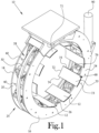
- FIG. 1 illustrates a perspective view of a transfer ring in an expanded position according to an example embodiment of the present general inventive concept
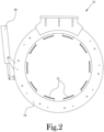
- FIG. 2 illustrates a front view of the transfer ring of FIG. 1 in the expanded position
- the transfer ring 10 includes a plurality of shoes 12 that are movable from an expanded to a contracted position, and vice versa, to grip an outer surface of a desired tire component for transfer to another location and/or device.
- various example embodiments of the present general inventive concept may include more or fewer components than those illustrated in these figures, and/or of different configurations, without departing from the scope of the present general inventive concept. Also, some components may be omitted from these figures and descriptions for the sake of clarity.
- the transfer ring 10 includes first and second circular frame members 14,16 disposed in a fixed, registered, side-by-side, parallel, and space apart relationship to one another.
- the first and second circular frame members 14,16 may be configured with substantially the same inner and outer diameters, and each may have a generally rectangular cross-section having respective inner and outer opposite flat side surfaces 18,20 and 22,24, respectively.
- a plurality of hinge pin connectors 26 extend between the first and second circular frame members 14,16 at spaced apart locations about the respective perimetral margins of the first and second circular frame members 14,16 to rigidly retain the side-by-side, parallel, registered, and spaced apart relationship of the first and second circular frame members 14,16, thereby defining a skeletal cage 25 having an open space 28 between the first and second circular frame members 14,16.
- FIG. 3 which illustrates a front view of the transfer ring 10 as depicted in FIG. 2 without the front, or first, frame member 14.
- a plurality of sets of driven linkages 41 are provided within the open space 28 of the skeletal cage 25.
- Each of the driven linkage sets 41 includes a first member 42 configured with an elongated geometry, and having a first end 43 which is pivotably coupled to a respective hinge pin connector 26 extending between the first and second circular frame members 14,16, and a second end 44 which extends generally inwardly of the skeletal cage 25.
- Each of the driven linkage sets 41 also includes a second member 45 configured with an elongated geometry, and having a first end 46 which is pivotably coupled to a portion of the circular drive member 30, and a second end 47 which is pivotably coupled to a portion of a corresponding first member 42, between the first end 43 and the second end 44 of the first member 42.
- Each of the driven linkage sets 41 also includes a third member 48 configured with an elongated geometry, and having a first end 49 which is pivotably coupled to a block portion 61 of a block-and-rail cam follower 60, and a second end 50 which is pivotably coupled to a corresponding shoe 12.
- Each second end 44 of each first member 42 is pivotably coupled to the third member 48 proximate a central portion of the third member 48.
- Each block portion 61 is configured to slidably follow a rail portion 62 of the block-and-rail cam follower 60, for example via an appropriate tongue-and-groove fitting, rollers, or the like.
- each respective rail portion 62 of the block-and-rail cam follower 60 is mounted along a portion of the inner surfaces 20,22 of the first and second frame members 14,16.
- grooves may be formed in the inner surfaces 20,22 of the first and second frame members 14,16 to receive the respective rail portions 62 of the block-and-rail cam followers 60, so as to provide a more secure fitting.
- each shoe 12 is pivotably coupled to a corresponding second end 50 of the third member 48 of the driven linkage sets 41 along a dimension parallel to the central axis of the skeletal cage 25.
- Each shoe 12 includes a plate 68 having an arcuate interior surface 70 facing substantially radially inwardly of the skeletal cage 25 and an outer surface 71 facing substantially radially outwardly of the skeletal cage 25.
- Each plate 68 defines first and second arcuate side edges 72,73, respectively, as well as first and second end edges 74,75, respectively, which extend at opposite ends of the arcuate plate 68 between the first and second side edges 72,73.
- the various shoes 12 are arranged in an end-to-end configuration with each first end edge 74 of each plate 68 extending generally along a second end edge 75 of an adjacent plate 68, such that the various arcuate interior surfaces 70 of the plates 68 of the shoes 12 cooperate to collectively establish a segmented cylindrical surface which, as will be further discussed below, is adapted to surround and grasp an object, such as, for example, a tire component.
- Each shoe further includes at least one wall 76 extending outwardly from the plate 68 generally perpendicular to the outer surface 71.
- a pair of walls 76 extend outwardly from the plate 68 at a parallel, spaced apart orientation to one another along an arcuate dimension of the plate 68.
- the walls 76 are spaced apart from one another a suitable distance to allow the second end 50 of the third member 48 of a corresponding one of the driven linkage sets 41 to be inserted therebetween, so as to be pivotably coupled to the inner surface of at least one of the walls 76.
- Suitable fastening means such as, for example, a plurality of axially-aligned through openings 77, may be provided along the walls 76 and through each corresponding third member 48 second end 50 to allow receipt therein of a pin, bolt, or other such rotatable connector, so as to allow each shoe 12 to be pivotably connected to the corresponding third member 48 second end 50.
- an internally-threaded set screw opening is provided opening perpendicular to an axial dimension of one of the through openings 77, such that upon receipt of a pin connector through the through openings 77 in the walls 76 and the third member 48 second end 50, a set screw (not shown) may be received within the set screw opening to secure the pin connector through the through openings 77.
- a set screw (not shown) may be received within the set screw opening to secure the pin connector through the through openings 77.
- suitable configurations which may be used to achieve a rotatable connection between each shoe 12 and a corresponding driven third member 48 second end 50, and such other configurations may be used without departing from the scope of the present general inventive concept.
- First and second grooves 78,79 may be defined along each wall 76 of each shoe 12, with each first groove 78 having at least one open end which opens toward an adjacent shoe 12, and with each second groove 79 having at least one open end which opens toward an opposite adjacent shoe 12.
- the first groove 78 is adapted to receive therein a first end 81 of a rigid guide rod 80 of sufficient length to span two adjacent ones of the shoes 12.
- the first end 81 of each guide rod 80 is anchored within its respective first groove 78 by a suitable fastener, such as for example a screw, bolt, weld, adhesive, or other fastener, or by an integral connection.
- An opposite second end 82 of each guide rod 80 extends into and is slidably received within the second groove 79 of an adjacent shoe 12.
- a power source 90 such as a piston/cylinder device, may be provided for effecting controlled rotation of the circular drive member 30 in relation to the skeletal cage 25.
- actuation of the power source 90 results in rotational movement of the circular drive member 30 in relation to the skeletal cage 25, which in turn rotates each driven linkage set 41 about its respective hinge connectors 26 between a contracted position, in which each second end 44 of each first member 42 of the respective driven linkage sets 41 is moved inwardly and thus causes the second end 50 of the third member 48 to move the corresponding shoe 12 inwardly toward the central axis of the circular drive member 30 and the first and second circular frame members 14,16, and an expanded position in which the driven linkage sets 41 are collapsed to bring the corresponding shoes 12 outwardly from the central axis of the circular drive member 30 and the first and second circular frame members 14,16.
- FIG. 4 illustrates a front view of the transfer ring of FIG. 1 in a contracted position
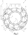
- FIG. 5 illustrates a front view of the transfer ring as depicted in FIG. 4 without the front frame member. Due to the linear movement action of the block-and-rail cam follower 60 controlling the first end 49 of the third member 48, which is linked to the first member 42, and to the second member 45 through the connection with the first member 42, the arcuate interior surface 70 of the shoe 12 moves toward the central axis of the circular drive member 30 and the first and second circular frame members 14,16 without circumferential movement about that central axis.
- FIGS. 6A-C illustrate different positions of a transfer ring shoe according to an example embodiment of the present general inventive concept as the shoe moves from the expanded position to the contracted position.
- FIG. 6A illustrates one of the shoes 12 in a fully expanded position
- FIG. 6B illustrates the shoe 12 being moved toward the central axis as the circular drive member 30 is rotated relative to the first and second frame members 14,16
- FIG. 6C illustrates the shoe 12 moved to the fully contracted position.
- first end 43 of the first member 42 is pivotably coupled to the inner flat surface 18 of the first frame member 14 (which has been omitted from this drawing for clarity), and the first end 46 of the second member 45 is pivotably coupled to the circular drive member 30, when the circular drive member is rotated (in a clockwise fashion in the views of FIGS.6A-C ) the first ends 43,46 of the first and second members 42,45 are brought in closer to proximity to one another.
- the shoes 12 are carried by the second ends 50 of the third members 48 radially outwardly from a central axis of the transfer ring 10 to an expanded configuration, wherein the interior surfaces 70 of the shoes 12 are separated from one another to increase the overall diameter of the segmented cylindrical surface used to grip the tire component.
- the shoes 12 are carried by the second ends 50 of the third members 48 radially inwardly toward a central axis of the transfer ring 10 to a contracted configuration, wherein the interior surfaces 70 of the shoes 12 are brought closer to one another to decrease the overall diameter of the segmented cylindrical surface.
- each of the first and second grooves 78,79 is oriented with respect to one another such that each of the guide rods 80 slide along its respective second groove 56 to cooperatively maintain the interior surfaces 70 of the shoes 12 with respect to one another in a generally cylindrical configuration throughout the above-discussed expansion and contraction of the shoes 12 between the expanded configuration and the contracted or collapsed configuration.
- each of the rail portions 62 of the block-and-rail cam follower 60 is oriented with respect to one another such that each of the driven linkages 41 limits its corresponding shoe 12 to linear movement radially inwardly and outwardly, toward and away from the central axis of the transfer ring 10, throughout contraction and expansion of the shoes 12 between the expanded configuration and the collapsed configuration.
- pairs of these driven linkage sets are provided side by side so as to be connected to both respective inner flat surfaces 18,22 of the first and second frame members 14,16, while also being connected to both respective sides of the circular drive member 30.
- Various example embodiments of the present general inventive concept may provide a transfer ring to use in the manufacture of vehicle tires, the transfer ring including a circular frame, a plurality of driven linkages coupled to the circular frame and configured to be movable between a contracted position and an expanded position, a drive member disposed along the circular frame, the drive member being coupled to the driven linkages and configured to drive the driven linkages between the contracted position and the expanded position, and a plurality of shoes having arcuate interior surfaces facing substantially radially inwardly toward a central axis to collectively define a substantially cylindrical segmented gripping surface, each of the shoes being coupled to at least one of the driven linkages so as to be selectively move toward and away from the central axis, wherein each of the driven linkages includes a first member coupled to the circular frame, a second member coupled to the drive member and the first member, a third member coupled to a corresponding one of the shoes and to the first member, and a block-and-rail cam follower configured such that a rail portion is fixed to
- the first member may have a first end pivotably coupled to the circular frame, and a second end pivotably coupled to a portion of the third member.
- the second end of the first member may be pivotably coupled to third member proximate a central portion of the third member.
- the second member may have a first end pivotably coupled to the drive member, and a second end pivotably coupled to a portion of the first member.
- the second end of the second member may be pivotably coupled to the first member at a point closer to the second end of the first member than the first end of the first member.
- the third member may have a first end pivotably coupled to the block portion of the block-and-rail cam follower, and a second end pivotably coupled to the shoe.
- the transfer ring may further include a plurality of grooves formed in the circular frame to receive the respective rail portions of the bock-and-rail cam followers of each of the driven linkages.
- a pair of driven linkages may be provided for each of the respective shoes.
- Each pair of driven linkages may be configured to be respectively coupled to opposite inner surfaces of the circular frame.
- the drive member may be configured as a circular drive member disposed between the inner surfaces of the circular frame.
Landscapes
- Engineering & Computer Science (AREA)
- Mechanical Engineering (AREA)
- Footwear And Its Accessory, Manufacturing Method And Apparatuses (AREA)
- Tyre Moulding (AREA)
Description
- The present general inventive concept relates to devices that are useful in the manufacture of vehicle tires. More particularly, the present general inventive concept relates to an improved transfer ring useful in the manufacture of vehicle tires.
- The manufacture of a vehicle tire commonly includes the steps of forming a tire carcass, forming a toroid-shaped belt and tread "package" of the tire separately from the carcass, and thereafter marrying the belt and tread package to the tire carcass to form a "green" tire. The green tire is thereafter treated to form the tread and various other features of a finished tire. Other supplementary steps, such as bonding the belt and tread package to the tire carcass (often referred to as "stitching" the belt and tread package), may be performed during the course of, or following, one or more of the aforementioned steps.
- Formation of a belt and tread package of a tire is typically accomplished using a belt and tread drum, of the type disclosed in
United States Patent No. 6,013,147 . Such a belt and tread drum typically has an outer cylindrical surface, or circumference, about which one or more layers of the tire belt material (comprising, for example, reinforcement cords embedded in a polymeric binder) are laid to define the belt and tread package. The circumference of the belt and tread drum is preferably capable of expanding and contracting to allow, for example, removal of a completed belt and tread package from the drum.
A completed belt and tread package is typically essentially nonexpandable radially. However, a completed belt and tread package is typically flexible to the extent that, when unsupported, the toroid-shaped belt and tread package will deform and sag under the influence of gravity. Also, desirably, the adjustable circumference of the belt and tread drum enables a single drum to be used to form belt and tread packages of alternative diameters. - In the manufacture of vehicle tires, a tire carcass is typically fabricated using a tire building drum, of the type described in
United States Patent No. 6,457,505 . Such a tire building drum typically defines a radially expandable and contractible cylindrical working surface, similar to the above-discussed belt and tread drum, upon which a tire carcass is formed. Subsequent to the formation of the tire carcass on the cylindrical working surface, such tire carcass typically is transferred to an expansion drum, of the type discussed inUnited States Patent No. 6,602,372 . The tire carcass is positioned surrounding the expansion drum, and a portion of the tire carcass is overlaid with the belt and tread package. The tire carcass is then inflated to a toroid shape resembling, though often not identical to, the shape of a finished tire. While the tire carcass is inflated, the belt and tread package is stitched to the tire carcass. - In the above-described process, the steps of transferring a tire carcass from a tire building drum to an expansion drum and transferring a belt and tread package to a tire carcass for stitching are typically both accomplished using one or more transfer rings, of the type described in
United States Patent No. 8,091,602 . Such a transfer ring typically includes a plurality of "shoe" segments having arced interior surfaces which collectively form a segmented, radially-inwardly-facing cylindrical surface suitable for grasping and holding a tire carcass and/or a belt and tread package. Each shoe segment is mounted on an appropriate linkage such that the shoes are collectively radially expandable and contractible with respect to one another, such that the diameter of the segmented, radially-inwardly-facing cylindrical surface can be expanded to fit over a tire carcass and/or belt and tread package, contracted to grasp the tire carcass or belt and tread package for transfer, and then re-expanded to release the tire carcass or belt and tread package following transfer. - When a transfer ring is used as described above to transfer a tire carcass and/or belt and tread package (hereinafter, collectively, "tire component"), it is not uncommon for the shoes and associated linkages of the transfer ring to be configured such that, as the transfer ring is contracted to bring the shoes radially inward around the tire component to grip the tire component, the linkages move each of the shoes along an arced path both radially inwardly and circumferentially around the central axis of the transfer ring. This type of motion is sometimes referred to as an "iris" motion pattern. In certain prior art transfer rings employing an iris motion pattern of the shoes, movement of the shoes both radially inwardly and circumferentially around the central axis of the transfer ring can, in some instances, result in the shoes imparting "twisting" forces to the tire component in a direction along a circumference of the tire component. These "twisting" forces can, in certain instances, be undesirable, and in some instances, can hinder efforts in maintaining structural integrity and a uniform shape of the tire component during transfer.
- In light of the above, it would be desirable to transfer tire components with a tire transfer ring which allows expansion and contraction of the shoes in a radial direction while inhibiting circumferential travel, and which maintains the alignment and stability of the shoes in the aforementioned segmented cylindrical shape in relation to one another.
-
US 2012/033906 A1 discloses a bearing axle adapted to rotatably secure a mounting ring between opposing interior surfaces of respective spaced apart first and second housing rings of a tire transfer ring and to allow removal of the bearing axle from between the housing rings absent additional separation of the housing rings. -
JP 2013 018274 A -
FR 3 059 936 A1 -
DE 10 2013 102583 A1 discloses a device for holding and transporting a tire belt for the production of a vehicle tire, with an annular base frame on which segment units with segment nests are arranged, which have segment supports for holding the tire belt on its outside, wherein the segment supports can be moved in the radial direction of the base frame and can be fixed in at least two different segment positions which correspond to different diameter ranges for holding tire belts for different tire dimensions. - Another transfer ring for holding an unvulcanized tire is disclosed in
JP S 58 179 633 - According to an aspect of the invention, there is provided a system according to claim 1. Further features according to embodiments of the invention are defined in the dependent claims.
- According to various example embodiments of the present general inventive concept, a transfer ring is provided that is equipped with a plurality of shoes arranged in a substantially circular configuration to define an inwardly- facing segmented cylindrical gripping surface, wherein each of the shoes is actuated by a plurality of linkages that allow for movement of the shoe in a linear direction radially inwardly and outwardly in relation to a central axis of the segmented cylindrical gripping surface.
- Additional aspects and advantages of the present general inventive concept will be set forth in part in the description which follows, and, in part, will be obvious from the description, or may be learned by practice of the present general inventive concept.
- The foregoing and/or other aspects and advantages of the present general inventive concept may be achieved by providing a transfer ring to use in the manufacture of vehicle tires, the transfer ring including a circular frame, a plurality of driven linkages coupled to the circular frame and configured to be movable between a contracted position and an expanded position, a drive member disposed along the circular frame, the drive member being coupled to the driven linkages and configured to drive the driven linkages between the contracted position and the expanded position, and a plurality of shoes having arcuate interior surfaces facing substantially radially inwardly toward a central axis to collectively define a substantially cylindrical segmented gripping surface, each of the shoes being coupled to at least one of the driven linkages so as to be selectively move toward and away from the central axis, wherein each of the driven linkages includes a first member coupled to the circular frame, a second member coupled to the drive member and the first member, a third member coupled to a corresponding one of the shoes and to the first member, and a block-and-rail cam follower configured such that a rail portion is fixed to the circular frame, and a block portion is coupled to the third member, wherein the driven linkages are configured to limit movement of the arcuate surface to linear movement radially toward and away from the central axis.
- Other features and aspects may be apparent from the following detailed description, the drawings, and the claims.
- The following example embodiments are representative of example techniques and structures designed to carry out the objects of the present general inventive concept, but the present general inventive concept is not limited to these example embodiments. In the accompanying drawings and illustrations, the sizes and relative sizes, shapes, and qualities of lines, entities, and regions may be exaggerated for clarity. A wide variety of additional embodiments will be more readily understood and appreciated through the following detailed description of the example embodiments, with reference to the accompanying drawings in which:
-
FIG. 1 illustrates a perspective view of a transfer ring in an expanded position according to an example embodiment of the present general inventive concept; -
FIG. 2 illustrates a front view of the transfer ring ofFIG. 1 in the expanded position; -
FIG. 3 illustrates a front view of the transfer ring as depicted inFIG. 2 without the front frame member; -
FIG. 4 illustrates a front view of the transfer ring ofFIG. 1 in a contracted position; -
FIG. 5 illustrates a front view of the transfer ring as depicted inFIG. 4 without the front frame member; and -
FIGS. 6A-C illustrate different positions of a transfer ring shoe according to an example embodiment of the present general inventive concept as the shoe moves from the expanded position to the contracted position. - Reference will now be made to the example embodiments of the present general inventive concept, examples of which are illustrated in the accompanying drawings and illustrations. The example embodiments are described herein in order to explain the present general inventive concept by referring to the figures.
- The following detailed description is provided to assist the reader in gaining a comprehensive understanding of the structures and fabrication techniques described herein. Accordingly, various changes, modification, and equivalents of the structures and fabrication techniques described herein will be suggested to those of ordinary skill in the art. The progression of fabrication operations described are merely examples, however, and the sequence type of operations is not limited to that set forth herein and may be changed as is known in the art, with the exception of operations necessarily occurring in a certain order. Also, description of well-known functions and constructions may be simplified and/or omitted for increased clarity and conciseness.
- Note that spatially relative terms, such as "up," "down," "right," "left," "beneath," "below," "lower," "above," "upper" and the like, may be used herein for ease of description to describe one element or feature's relationship to another element(s) or feature(s) as illustrated in the figures. Spatially relative terms are intended to encompass different orientations of the device in use or operation in addition to the orientation depicted in the figures. For example, if the device in the figures is turned over or rotated, elements described as "below" or "beneath" other elements or features would then be oriented "above" the other elements or features. Thus, the exemplary term "below" can encompass both an orientation of above and below. The device may be otherwise oriented (rotated 90 degrees or at other orientations) and the spatially relative descriptors used herein interpreted accordingly.
- According to various example embodiments of the present general inventive concept, a transfer ring is provided that is equipped with a plurality of shoes arranged in a substantially circular configuration to define an inwardly- facing segmented cylindrical gripping surface, wherein each of the shoes is actuated by a plurality of linkages that allow for movement of the shoe in a linear direction radially inwardly and outwardly in relation to a central axis of the segmented cylindrical gripping surface. In various example embodiments the inward and outward movement of the shoes is guided by driven linkage sets including a block-and-rail cam follower that limits the movement of the shoes to radial movement relative to the central axis, inhibiting any circumferential travel about the central axis by the shoe.
-
FIG. 1 illustrates a perspective view of a transfer ring in an expanded position according to an example embodiment of the present general inventive concept, andFIG. 2 illustrates a front view of the transfer ring ofFIG. 1 in the expanded position. In this example embodiment thetransfer ring 10 includes a plurality ofshoes 12 that are movable from an expanded to a contracted position, and vice versa, to grip an outer surface of a desired tire component for transfer to another location and/or device. It is understood that various example embodiments of the present general inventive concept may include more or fewer components than those illustrated in these figures, and/or of different configurations, without departing from the scope of the present general inventive concept. Also, some components may be omitted from these figures and descriptions for the sake of clarity. Thetransfer ring 10 includes first and secondcircular frame members circular frame members - A plurality of
hinge pin connectors 26 extend between the first and secondcircular frame members circular frame members circular frame members skeletal cage 25 having anopen space 28 between the first and secondcircular frame members - Within the
open space 28 of theskeletal cage 25, there is disposed acircular drive member 30 mounted in side-by-side, parallel, and coaxial relationship to the first and secondcircular frame members rollers 40 extending between the first and secondcircular frame members drive member 30 is disposed between the first and secondcircular frame member drive member 30 with respect to theskeletal cage 25. The components and mechanisms between the first and secondcircular frame members FIG. 3 , which illustrates a front view of thetransfer ring 10 as depicted inFIG. 2 without the front, or first,frame member 14. A plurality of sets of drivenlinkages 41 are provided within theopen space 28 of theskeletal cage 25. Each of the driven linkage sets 41 includes afirst member 42 configured with an elongated geometry, and having afirst end 43 which is pivotably coupled to a respectivehinge pin connector 26 extending between the first and secondcircular frame members second end 44 which extends generally inwardly of theskeletal cage 25. Each of the driven linkage sets 41 also includes asecond member 45 configured with an elongated geometry, and having afirst end 46 which is pivotably coupled to a portion of thecircular drive member 30, and asecond end 47 which is pivotably coupled to a portion of a correspondingfirst member 42, between thefirst end 43 and thesecond end 44 of thefirst member 42. Each of the driven linkage sets 41 also includes athird member 48 configured with an elongated geometry, and having afirst end 49 which is pivotably coupled to a block portion 61 of a block-and-rail cam follower 60, and asecond end 50 which is pivotably coupled to a correspondingshoe 12. Eachsecond end 44 of eachfirst member 42 is pivotably coupled to thethird member 48 proximate a central portion of thethird member 48. Each block portion 61 is configured to slidably follow arail portion 62 of the block-and-rail cam follower 60, for example via an appropriate tongue-and-groove fitting, rollers, or the like. In the illustrated embodiments, eachrespective rail portion 62 of the block-and-rail cam follower 60 is mounted along a portion of theinner surfaces second frame members inner surfaces second frame members respective rail portions 62 of the block-and-rail cam followers 60, so as to provide a more secure fitting. - As previously described, a plurality of articulating
shoes 12 are provided, with eachshoe 12 being pivotably coupled to a correspondingsecond end 50 of thethird member 48 of the driven linkage sets 41 along a dimension parallel to the central axis of theskeletal cage 25. Eachshoe 12 includes aplate 68 having an arcuateinterior surface 70 facing substantially radially inwardly of theskeletal cage 25 and anouter surface 71 facing substantially radially outwardly of theskeletal cage 25. Eachplate 68 defines first and second arcuate side edges 72,73, respectively, as well as first and second end edges 74,75, respectively, which extend at opposite ends of thearcuate plate 68 between the first and second side edges 72,73. Thevarious shoes 12 are arranged in an end-to-end configuration with eachfirst end edge 74 of eachplate 68 extending generally along asecond end edge 75 of anadjacent plate 68, such that the various arcuateinterior surfaces 70 of theplates 68 of theshoes 12 cooperate to collectively establish a segmented cylindrical surface which, as will be further discussed below, is adapted to surround and grasp an object, such as, for example, a tire component. - Each shoe further includes at least one
wall 76 extending outwardly from theplate 68 generally perpendicular to theouter surface 71. In the illustrated embodiment, a pair ofwalls 76 extend outwardly from theplate 68 at a parallel, spaced apart orientation to one another along an arcuate dimension of theplate 68. - The
walls 76 are spaced apart from one another a suitable distance to allow thesecond end 50 of thethird member 48 of a corresponding one of the driven linkage sets 41 to be inserted therebetween, so as to be pivotably coupled to the inner surface of at least one of thewalls 76. Suitable fastening means, such as, for example, a plurality of axially-aligned throughopenings 77, may be provided along thewalls 76 and through each correspondingthird member 48second end 50 to allow receipt therein of a pin, bolt, or other such rotatable connector, so as to allow eachshoe 12 to be pivotably connected to the correspondingthird member 48second end 50. In the illustrated embodiment, an internally-threaded set screw opening is provided opening perpendicular to an axial dimension of one of the throughopenings 77, such that upon receipt of a pin connector through the throughopenings 77 in thewalls 76 and thethird member 48second end 50, a set screw (not shown) may be received within the set screw opening to secure the pin connector through the throughopenings 77. However, it will be understood that other suitable configurations exist which may be used to achieve a rotatable connection between eachshoe 12 and a corresponding driventhird member 48second end 50, and such other configurations may be used without departing from the scope of the present general inventive concept. - First and
second grooves wall 76 of eachshoe 12, with eachfirst groove 78 having at least one open end which opens toward anadjacent shoe 12, and with eachsecond groove 79 having at least one open end which opens toward an oppositeadjacent shoe 12. Thefirst groove 78 is adapted to receive therein afirst end 81 of arigid guide rod 80 of sufficient length to span two adjacent ones of theshoes 12. Thefirst end 81 of eachguide rod 80 is anchored within its respectivefirst groove 78 by a suitable fastener, such as for example a screw, bolt, weld, adhesive, or other fastener, or by an integral connection. An oppositesecond end 82 of eachguide rod 80 extends into and is slidably received within thesecond groove 79 of anadjacent shoe 12. - A
power source 90, such as a piston/cylinder device, may be provided for effecting controlled rotation of thecircular drive member 30 in relation to theskeletal cage 25. Thus, actuation of thepower source 90 results in rotational movement of thecircular drive member 30 in relation to theskeletal cage 25, which in turn rotates each driven linkage set 41 about itsrespective hinge connectors 26 between a contracted position, in which eachsecond end 44 of eachfirst member 42 of the respective driven linkage sets 41 is moved inwardly and thus causes thesecond end 50 of thethird member 48 to move the correspondingshoe 12 inwardly toward the central axis of thecircular drive member 30 and the first and secondcircular frame members shoes 12 outwardly from the central axis of thecircular drive member 30 and the first and secondcircular frame members FIG. 4 illustrates a front view of the transfer ring ofFIG. 1 in a contracted position, andFIG. 5 illustrates a front view of the transfer ring as depicted inFIG. 4 without the front frame member. Due to the linear movement action of the block-and-rail cam follower 60 controlling thefirst end 49 of thethird member 48, which is linked to thefirst member 42, and to thesecond member 45 through the connection with thefirst member 42, the arcuateinterior surface 70 of theshoe 12 moves toward the central axis of thecircular drive member 30 and the first and secondcircular frame members -
FIGS. 6A-C illustrate different positions of a transfer ring shoe according to an example embodiment of the present general inventive concept as the shoe moves from the expanded position to the contracted position.FIG. 6A illustrates one of theshoes 12 in a fully expanded position,FIG. 6B illustrates theshoe 12 being moved toward the central axis as thecircular drive member 30 is rotated relative to the first andsecond frame members FIG. 6C illustrates theshoe 12 moved to the fully contracted position. As thefirst end 43 of thefirst member 42 is pivotably coupled to the innerflat surface 18 of the first frame member 14 (which has been omitted from this drawing for clarity), and thefirst end 46 of thesecond member 45 is pivotably coupled to thecircular drive member 30, when the circular drive member is rotated (in a clockwise fashion in the views ofFIGS.6A-C ) the first ends 43,46 of the first andsecond members second end 47 of the second member and thefirst member 42 to move generally inward toward the central axis, which in turn causes thesecond end 50 of thethird member 48 to also move generally inward toward the central axis. This movement is guided by the sliding of the block portion 61 along therail portion 62 of the block-and-rail cam follower 60, therail portion 62 being fixed to the innerflat surface 18 of the first frame member 14 (again, removed for this drawing), to move theshoe 12 inwardly and directly toward the central axis of thecircular drive member 30 and the first andsecond frame members shoe 12 is inhibited by the driven linkage set 41 with the block-and-rail cam follower 60. Thus, the drivenlinkages 41 are configured to rotate between the expanded position and the collapsed position upon appropriate rotation of thecircular drive member 30 in relation to the skeletal cage. Thus, upon rotation of thecircular drive member 30 to the expanded position, theshoes 12 are carried by the second ends 50 of thethird members 48 radially outwardly from a central axis of thetransfer ring 10 to an expanded configuration, wherein the interior surfaces 70 of theshoes 12 are separated from one another to increase the overall diameter of the segmented cylindrical surface used to grip the tire component. Conversely, upon rotation of thecircular drive member 30 to the contracted position, theshoes 12 are carried by the second ends 50 of thethird members 48 radially inwardly toward a central axis of thetransfer ring 10 to a contracted configuration, wherein the interior surfaces 70 of theshoes 12 are brought closer to one another to decrease the overall diameter of the segmented cylindrical surface. To this end, each of the first andsecond grooves guide rods 80 slide along its respective second groove 56 to cooperatively maintain theinterior surfaces 70 of theshoes 12 with respect to one another in a generally cylindrical configuration throughout the above-discussed expansion and contraction of theshoes 12 between the expanded configuration and the contracted or collapsed configuration. Likewise, each of therail portions 62 of the block-and-rail cam follower 60 is oriented with respect to one another such that each of the drivenlinkages 41 limits its correspondingshoe 12 to linear movement radially inwardly and outwardly, toward and away from the central axis of thetransfer ring 10, throughout contraction and expansion of theshoes 12 between the expanded configuration and the collapsed configuration. It is understood that while single driven linkage sets 41 are illustrated inFIGS. 6A-C , in various example embodiments, such as that illustrated inFIG. 1 , pairs of these driven linkage sets are provided side by side so as to be connected to both respective innerflat surfaces second frame members circular drive member 30. - Various example embodiments of the present general inventive concept may provide a transfer ring to use in the manufacture of vehicle tires, the transfer ring including a circular frame, a plurality of driven linkages coupled to the circular frame and configured to be movable between a contracted position and an expanded position, a drive member disposed along the circular frame, the drive member being coupled to the driven linkages and configured to drive the driven linkages between the contracted position and the expanded position, and a plurality of shoes having arcuate interior surfaces facing substantially radially inwardly toward a central axis to collectively define a substantially cylindrical segmented gripping surface, each of the shoes being coupled to at least one of the driven linkages so as to be selectively move toward and away from the central axis, wherein each of the driven linkages includes a first member coupled to the circular frame, a second member coupled to the drive member and the first member, a third member coupled to a corresponding one of the shoes and to the first member, and a block-and-rail cam follower configured such that a rail portion is fixed to the circular frame, and a block portion is coupled to the third member, wherein the driven linkages are configured to limit movement of the arcuate surface to linear movement radially toward and away from the central axis. The first member may have a first end pivotably coupled to the circular frame, and a second end pivotably coupled to a portion of the third member. The second end of the first member may be pivotably coupled to third member proximate a central portion of the third member. The second member may have a first end pivotably coupled to the drive member, and a second end pivotably coupled to a portion of the first member. The second end of the second member may be pivotably coupled to the first member at a point closer to the second end of the first member than the first end of the first member. The third member may have a first end pivotably coupled to the block portion of the block-and-rail cam follower, and a second end pivotably coupled to the shoe. The transfer ring may further include a plurality of grooves formed in the circular frame to receive the respective rail portions of the bock-and-rail cam followers of each of the driven linkages. A pair of driven linkages may be provided for each of the respective shoes. Each pair of driven linkages may be configured to be respectively coupled to opposite inner surfaces of the circular frame. The drive member may be configured as a circular drive member disposed between the inner surfaces of the circular frame.
- Numerous variations, modifications, and additional embodiments are possible, and accordingly, all such variations, modifications, and embodiments are to be regarded as being within the scope of the present general inventive concept. For example, regardless of the content of any portion of this application, unless clearly specified to the contrary, there is no requirement for the inclusion in any claim herein or of any application claiming priority hereto of any particular described or illustrated activity or element, any particular sequence of such activities, or any particular interrelationship of such elements. Moreover, any activity can be repeated, any activity can be performed by multiple entities, and/or any element can be duplicated.
- It is noted that the simplified diagrams and drawings included in the present application do not illustrate all the various connections and assemblies of the various components, however, those skilled in the art will understand how to implement such connections and assemblies, based on the illustrated components, figures, and descriptions provided herein, using sound engineering judgment. Numerous variations, modification, and additional embodiments are possible, and, accordingly, all such variations, modifications, and embodiments are to be regarded as being within the scope of the present general inventive concept.
- While the present general inventive concept has been illustrated by description of several example embodiments, and while the illustrative embodiments have been described in detail, it is not the intention of the applicant to restrict or in any way limit the scope of the general inventive concept to such descriptions and illustrations. Instead, the descriptions, drawings, and claims herein are to be regarded as illustrative in nature, and not as restrictive, and additional embodiments will readily appear to those skilled in the art upon reading the above description and drawings. Additional modifications will readily appear to those skilled in the art. Accordingly, departures may be made from such details without departing from the scope of applicant's general inventive concept.
Claims (10)
- A transfer ring (10) to use in the manufacture of vehicle tires, the transfer ring (10) comprising:a circular frame (14, 16);a plurality of driven linkages (41) coupled to the circular frame (14, 16) and configured to be movable between a contracted position and an expanded position;a drive member (30) disposed along the circular frame (14, 16), the drive member (30) being coupled to the driven linkages (41) and configured to drive the driven linkages (41) between the contracted position and the expanded position; anda plurality of shoes (12) having arcuate interior surfaces (70) facing substantially radially inwardly toward a central axis to collectively define a substantially cylindrical segmented gripping surface, each of the shoes (12) being coupled to at least one of the driven linkages (41) so as to be selectively move toward and away from the central axis;wherein each of the driven linkages (41) comprises:a first member (42) coupled to the circular frame (14, 16),a second member (45) coupled to the drive member (30) and the first member (42), a third member (48) coupled to a corresponding one of the shoes (12) and to the first member (42), anda block-and-rail cam follower (60) configured such that a rail portion (62) is fixed to the circular frame (14, 16), and a block portion (61) is coupled to the third member (48);wherein the driven linkages (41) are configured to limit movement of the arcuate surface (70) to linear movement radially toward and away from the central axis.
- The transfer ring (10) of claim 1, wherein the first member (42) has a first end (43) pivotably coupled to the circular frame (14, 16), and a second end (44) pivotably coupled to a portion of the third member (48).
- The transfer ring (10) of claim 2, wherein the second end (44) of the first member (42) is pivotably coupled to the third member (48) proximate a central portion of the third member (48).
- The transfer ring (10) of claim 1, wherein the second member (45) has a first end (46) pivotably coupled to the drive member (30), and a second end (47) pivotably coupled to a portion of the first member (42).
- The transfer ring (10) of claim 4, wherein the second end (47) of the second member (45) is pivotably coupled to the first member (42) at a point closer to a second end (44) of the first member (42) than a first end (43) of the first member (42).
- The transfer ring (10) of claim 1, wherein the third member (48) has a first end (49) pivotably coupled to the block portion (61) of the block-and-rail cam follower (60), and a second end (50) pivotably coupled to the shoe (12).
- The transfer ring (10) of claim 1, further comprising a plurality of grooves formed in the circular frame (14, 16) to receive the respective rail portions (62) of the block-and-rail cam followers (60) of each of the driven linkages (41).
- The transfer ring (10) of claim 1, wherein a pair of driven linkages (41) are provided for each of the respective shoes (12).
- The transfer ring (10) of claim 8, wherein each pair of driven linkages (41) are configured to be respectively coupled to opposite inner surfaces (20, 22) of the circular frame (14, 16).
- The transfer ring (10) of claim 9, wherein the drive member (30) is configured as a circular drive member disposed between the inner surfaces (20, 22) of the circular frame (14, 16).
Applications Claiming Priority (2)
| Application Number | Priority Date | Filing Date | Title |
|---|---|---|---|
| US201862737536P | 2018-09-27 | 2018-09-27 | |
| PCT/US2019/053428 WO2020069300A1 (en) | 2018-09-27 | 2019-09-27 | Transfer ring with block and rail system |
Publications (4)
| Publication Number | Publication Date |
|---|---|
| EP3856504A1 EP3856504A1 (en) | 2021-08-04 |
| EP3856504A4 EP3856504A4 (en) | 2022-11-16 |
| EP3856504B1 true EP3856504B1 (en) | 2024-11-06 |
| EP3856504C0 EP3856504C0 (en) | 2024-11-06 |
Family
ID=69947083
Family Applications (1)
| Application Number | Title | Priority Date | Filing Date |
|---|---|---|---|
| EP19864397.5A Active EP3856504B1 (en) | 2018-09-27 | 2019-09-27 | Transfer ring with block and rail system |
Country Status (5)
| Country | Link |
|---|---|
| US (1) | US11358356B2 (en) |
| EP (1) | EP3856504B1 (en) |
| JP (1) | JP7332702B2 (en) |
| CN (1) | CN112770896B (en) |
| WO (1) | WO2020069300A1 (en) |
Families Citing this family (7)
| Publication number | Priority date | Publication date | Assignee | Title |
|---|---|---|---|---|
| EP3917765B1 (en) | 2019-01-28 | 2024-03-27 | Davian Enterprises, LLC | Expandable belt and tread drum with reverse offset fingers |
| EP4139120B1 (en) | 2020-04-22 | 2025-08-06 | William A. Jones | Shoulder assembly for tire building machine |
| KR102834419B1 (en) * | 2020-05-29 | 2025-07-14 | 케네쓰 맥클리리 | Transfer ring and transfer ring shoe with reduced air entrapment feature |
| IT202100019721A1 (en) * | 2021-07-23 | 2023-01-23 | Marangoni Mecc S P A | METHOD AND ASSEMBLY FOR PICK-UP AND TRANSFER OF A SEMI-FINISHED PRODUCT IN A TIRE FORMING PLANT |
| EP3991957A1 (en) * | 2020-11-02 | 2022-05-04 | Marangoni Meccanica S.P.A. | Gripping and transfer apparatus and method for gripping and transferring a semi-finished product in a tyre forming plant |
| WO2022120117A2 (en) | 2020-12-03 | 2022-06-09 | Davian Enterprises, Llc (Dba Wyko Tire Technologies) | Expandable belt and tread drum with magnetic deck fixing |
| CN116250878B (en) * | 2021-12-10 | 2025-05-30 | 苏州微创骨科医疗工具有限公司 | Wire cutting equipment |
Citations (1)
| Publication number | Priority date | Publication date | Assignee | Title |
|---|---|---|---|---|
| JPS58179633A (en) * | 1982-04-03 | 1983-10-20 | Kobe Steel Ltd | Gripping device of unvulcanized tire |
Family Cites Families (168)
| Publication number | Priority date | Publication date | Assignee | Title |
|---|---|---|---|---|
| USRE22369E (en) | 1943-08-31 | Collapsible form | ||
| US1233567A (en) | 1916-10-07 | 1917-07-17 | William C Furry | Mold for forming concrete structures. |
| US1750728A (en) | 1928-04-30 | 1930-03-18 | George A Robison | Well-tool grab |
| US2168897A (en) | 1937-03-23 | 1939-08-08 | Akron Standard Mold Co | Tire building drum |
| US2353767A (en) | 1937-12-29 | 1944-07-18 | Akron Standard Mold Co | Tire building drum |
| US2201469A (en) | 1938-03-07 | 1940-05-21 | Akron Standard Mold Co | Collapsible form |
| US2335169A (en) | 1941-04-19 | 1943-11-23 | Akron Standard Mold Co | Tire-making drum |
| US2367831A (en) | 1942-11-24 | 1945-01-23 | Firestone Tire & Rubber Co | Collapsible form |
| US2529861A (en) | 1945-09-01 | 1950-11-14 | White S Dental Mfg Co | Adjustable seat supporting structure |
| US2614057A (en) | 1951-02-21 | 1952-10-14 | Us Rubber Co | Tire building drum |
| US2699198A (en) | 1951-08-04 | 1955-01-11 | Goodrich Co B F | Tire building drum |
| US2715932A (en) | 1953-03-04 | 1955-08-23 | Goodyear Tire & Rubber | Tire building drum |
| US2728616A (en) | 1953-11-24 | 1955-12-27 | Fafnir Bearing Co | Bearing |
| FR1227567A (en) | 1958-06-05 | 1960-08-22 | Firestone Tire & Rubber Co | Tire forming drum |
| US3101289A (en) | 1959-04-24 | 1963-08-20 | Pirelli | Method of making expansible tubular diaphragms for tire building drums |
| FR1242880A (en) | 1959-06-25 | 1960-10-07 | Kleber Colombes | Tire building drum |
| NL253095A (en) | 1959-07-03 | |||
| US3207648A (en) | 1962-02-01 | 1965-09-21 | Akron Standard Mold Co | Tire building apparatus |
| US3140216A (en) | 1962-04-18 | 1964-07-07 | Akron Standard Mold Co | Precision tire building drum |
| US3405023A (en) | 1964-05-19 | 1968-10-08 | Goodrich Co B F | Tire building drum |
| US3346434A (en) | 1964-06-09 | 1967-10-10 | Akron Standard Mold Co | Tire building drum |
| GB1050820A (en) | 1964-08-19 | |||
| US3507528A (en) | 1965-02-16 | 1970-04-21 | Westinghouse Electric Corp | Locking device |
| US3375154A (en) | 1965-04-09 | 1968-03-26 | Akron Standard Mold Co | Tire building drum |
| US3408244A (en) | 1965-04-28 | 1968-10-29 | Nat Standard Co | Tire assembling apparatus and apparatus for forming side walls for tires |
| US3489634A (en) | 1965-06-24 | 1970-01-13 | Uniroyal Inc | Apparatus for building tires and the like |
| FR95396E (en) | 1966-02-25 | 1970-09-11 | Nrm Corp | Radial carcass tire making drum. |
| US3485700A (en) | 1966-07-20 | 1969-12-23 | Ralph F Cooper | Tire building drum |
| NL6716660A (en) | 1966-12-30 | 1968-07-01 | ||
| BG18591A3 (en) | 1967-02-08 | 1975-02-25 | ||
| FR1531460A (en) | 1967-04-26 | 1968-07-05 | Uniroyal Englebert France | Axially collapsible and retractable pulley |
| US3695974A (en) | 1970-03-09 | 1972-10-03 | Gen Tire & Rubber Co | Tire building drum |
| US3644162A (en) | 1970-07-06 | 1972-02-22 | Goodyear Tire & Rubber | Tire-building drum |
| US3676261A (en) | 1970-07-06 | 1972-07-11 | Goodyear Tire & Rubber | Bead setting and ply turnup apparatus |
| US3784426A (en) | 1970-12-18 | 1974-01-08 | Goodyear Tire & Rubber | Method of building tires |
| US3787262A (en) | 1971-09-24 | 1974-01-22 | Goodyear Tire & Rubber | Tire building drum |
| US3833444A (en) | 1972-01-19 | 1974-09-03 | Nat Standard Co | Tire building apparatus of building tires |
| US3816218A (en) | 1972-03-29 | 1974-06-11 | Goodyear Tire & Rubber | Tire building drum |
| JPS5217063B2 (en) | 1972-04-11 | 1977-05-13 | ||
| US3837968A (en) | 1972-11-20 | 1974-09-24 | Goodyear Tire & Rubber | Tire building drum |
| JPS5121669B2 (en) | 1972-12-07 | 1976-07-03 | ||
| US3867229A (en) | 1974-02-01 | 1975-02-18 | Goodyear Tire & Rubber | Tire building drum |
| JPS532474B2 (en) | 1974-04-15 | 1978-01-28 | ||
| CA1062594A (en) | 1974-05-22 | 1979-09-18 | Frank R. Jellison | Building machine having an infinite number of drum settings |
| US4131500A (en) | 1974-12-09 | 1978-12-26 | Avon Tyres Limited | Tire building drum |
| US4010058A (en) | 1975-05-16 | 1977-03-01 | The Goodyear Tire & Rubber Company | Tire building drum |
| US4105487A (en) | 1975-12-27 | 1978-08-08 | Bridgestone Tire Company Limited | Process of and an apparatus for producing green tires |
| GB1568858A (en) | 1977-03-10 | 1980-06-04 | Vni I Konstrukt I Oborud Dlya | Tyre-building drum |
| US4128450A (en) | 1977-03-30 | 1978-12-05 | Nrm Corporation | Tire component building drum |
| JPS53140388A (en) | 1977-05-13 | 1978-12-07 | Bridgestone Tire Co Ltd | Tire forming apparatus |
| JPS5463184A (en) | 1977-10-28 | 1979-05-21 | Bridgestone Tire Co Ltd | Tire forming drum |
| US4230517A (en) | 1978-03-15 | 1980-10-28 | Nrm Corporation | Modular tire building machine |
| US4149927A (en) | 1978-03-24 | 1979-04-17 | The General Tire & Rubber Company | Tire building apparatus with improved drum shoulder |
| US4155796A (en) | 1978-06-28 | 1979-05-22 | The Goodyear Tire & Rubber Company | Single section tire building drum |
| US4210482A (en) | 1978-10-25 | 1980-07-01 | Eaton Corporation | Variable width tire building drum |
| US4324604A (en) | 1978-12-22 | 1982-04-13 | The General Tire & Rubber Co. | Bead setting apparatus with retractable flange |
| JPS55103942A (en) | 1979-02-01 | 1980-08-08 | Bridgestone Corp | Forming drum for tyre |
| US4239579A (en) | 1979-05-25 | 1980-12-16 | The Goodyear Tire & Rubber Company | Tire building drum |
| US4312696A (en) | 1980-03-12 | 1982-01-26 | National-Standard Company | Tire building apparatus |
| US4325764A (en) | 1980-06-19 | 1982-04-20 | The Goodyear Tire & Rubber Company | Drum and method of shaping a radial tire |
| IT1133894B (en) | 1980-10-15 | 1986-07-24 | Pirelli | IMPROVEMENTS IN PROCESSES AND EQUIPMENT FOR THE MANUFACTURE OF TIRES |
| US4473427A (en) | 1981-06-12 | 1984-09-25 | Mitsubishi Jukogyo Kabushiki Kaisha | Radial tire manufacture apparatus |
| US4425180A (en) | 1981-07-08 | 1984-01-10 | Vsesojuzny Nauchno-Issledovatelsky I Konstruktorsky Institut Po Oborudovaniju Dlya Shinnoi Promyshlennosti | Tire casing assembly drum |
| IT1145094B (en) | 1981-09-16 | 1986-11-05 | Martinson Srl | SELF-CENTERING BEZEL |
| US4469546A (en) | 1981-12-16 | 1984-09-04 | Cooper Tire & Rubber Company | Transfer ring for a tire building machine |
| US4445962A (en) | 1982-07-01 | 1984-05-01 | The B. F. Goodrich Company | Tire building drum |
| JPS5912834A (en) | 1982-07-13 | 1984-01-23 | Bridgestone Corp | Forming drum for radial tyre forming machine |
| US4436574A (en) | 1982-12-13 | 1984-03-13 | Eagle-Picher Industries, Inc. | Radial mandrel |
| JPS59120438A (en) | 1982-12-27 | 1984-07-12 | Bridgestone Corp | Tire molding equipment |
| JPS59202837A (en) | 1983-05-02 | 1984-11-16 | Bridgestone Corp | Tire molding apparatus |
| US4582557A (en) | 1983-12-12 | 1986-04-15 | Nrm Corporation | Tire building machine and method |
| GB8403351D0 (en) | 1984-02-08 | 1984-03-14 | Wyko Equipment Ltd | Tyre building drum |
| US4626302A (en) | 1984-09-24 | 1986-12-02 | The Goodyear Tire & Rubber Company | Tire building apparatus and method |
| DE3536816A1 (en) | 1985-10-16 | 1987-04-16 | Josef Maier | FORMWORK FOR ROUND OR MULTI-SIDED BUILDINGS |
| US4780171A (en) | 1987-08-13 | 1988-10-25 | Wyko Incorporated | Tire building machine |
| US4861173A (en) | 1987-08-17 | 1989-08-29 | Advanced Graphics Technology, Inc. | Bearing locking apparatus |
| US4861123A (en) | 1987-10-19 | 1989-08-29 | Waterloo Industries, Inc. | Integral slide formed from drawer shell |
| US4798647A (en) | 1988-01-25 | 1989-01-17 | Haas Herbert G | Releasable mounting assembly for tire building drum |
| JP2706974B2 (en) | 1989-04-25 | 1998-01-28 | 株式会社ブリヂストン | Method of folding back tire components |
| DE3925083A1 (en) | 1989-07-28 | 1991-01-31 | Continental Ag | METHOD AND DEVICE FOR PRODUCING A TIRE BLANK ON A BOMBING LEVEL |
| EP0431854B1 (en) | 1989-12-04 | 1995-02-22 | Sumitomo Rubber Industries Limited | Drum for assembling tyre component material |
| US5089077A (en) | 1990-03-08 | 1992-02-18 | Wyko, Incorporated | Apparatus for manufacturing multiple-ply tire carcasses |
| US5047108A (en) | 1990-03-09 | 1991-09-10 | Wyko, Inc. | Tire building drum for fabricating high profile type tire carcasses |
| US5066354A (en) | 1990-05-25 | 1991-11-19 | Cooper Tire And Rubber Company | Building drum for a tire belt-tread stock package |
| NL9001645A (en) | 1990-07-19 | 1992-02-17 | Vmi Epe Holland | MECHANISM FOR SUPPORTING AND FASTENING THE HEELS IN CONSTRUCTION OF AIR TIRES. |
| JPH0645194B2 (en) | 1990-07-24 | 1994-06-15 | 住友ゴム工業株式会社 | Beadlock method and apparatus for green tire molding machine |
| JPH07102628B2 (en) | 1991-04-30 | 1995-11-08 | 住友ゴム工業株式会社 | Ring member forming device |
| JP3193417B2 (en) | 1991-10-07 | 2001-07-30 | 株式会社ブリヂストン | Drum for tire building |
| US5320701A (en) | 1992-11-04 | 1994-06-14 | Illinois Tool Works Inc. | Tire building drum |
| EP0613767B1 (en) | 1993-03-04 | 1998-06-10 | Bridgestone Corporation | Method of forming a green tyre |
| JP2652129B2 (en) | 1993-07-02 | 1997-09-10 | 住友ゴム工業株式会社 | Transfer for tire molding |
| JP2719879B2 (en) | 1993-08-19 | 1998-02-25 | 住友ゴム工業株式会社 | Transfer for tire molding |
| IT1271479B (en) | 1993-10-11 | 1997-05-28 | Pirelli | METHOD AND EQUIPMENT FOR THE CAPPING OF A COATING STRUCTURE ON A CIRCLE FOR VEHICLE TIRES |
| US5354405A (en) | 1993-11-18 | 1994-10-11 | Wyko, Inc. | Bead lock drum for use in the manufacture of vehicle tires |
| IT1261153B (en) | 1993-12-30 | 1996-05-09 | Bridgestone Firestone Tech | TRANSFER RING FOR TOROID CASES |
| US5618374A (en) | 1994-02-10 | 1997-04-08 | Wyko, Inc. | Belt and tread drum for vehicle tire making machine |
| US5441587A (en) | 1994-08-12 | 1995-08-15 | Wyko, Inc. | Transfer ring having selective adjustability of shoe movement |
| JP3467120B2 (en) | 1995-06-06 | 2003-11-17 | 株式会社ブリヂストン | Tire building machine |
| US5635016A (en) | 1995-10-24 | 1997-06-03 | Wyko, Inc. | Transfer ring or drum apparatus with adjustable circumference |
| US5709768A (en) | 1995-10-24 | 1998-01-20 | Wyko, Inc. | Apparatus with adjustable circumference made up of a plurality of interconnected shoes |
| IT1281105B1 (en) | 1995-12-22 | 1998-02-11 | Bridgestone Firestone Tech | TIRE FORMING DRUM |
| US5735995A (en) | 1996-02-13 | 1998-04-07 | The Steelastic Company, L.L.C. | Apparatus for applying an apex filler to a bead ring |
| CA2219387C (en) | 1996-10-29 | 2006-08-15 | Wyko, Inc. | Apparatus with adjustable circumference made up of a plurality of interconnected shoes |
| GB2323573A (en) | 1997-03-26 | 1998-09-30 | Sumitomo Rubber Ind | Pneumatic tyre |
| DE19742035C1 (en) | 1997-09-24 | 1999-04-08 | Continental Ag | Method and drum as a device for building a green tire |
| US6004250A (en) | 1997-09-30 | 1999-12-21 | Wyko, Inc. | System and method for releaseably attaching outer segments to a drum useful in the manufacture of vehicle tires |
| JP4559549B2 (en) | 1998-03-04 | 2010-10-06 | 株式会社ブリヂストン | Pneumatic radial tire |
| US6007268A (en) | 1998-04-24 | 1999-12-28 | Specialized Marketing International, Inc. | Radial and axial locking release collar |
| US6058999A (en) | 1998-05-04 | 2000-05-09 | Wyko, Inc. | Tire manufacturing drum having simultaneous axial and radial adjustability |
| US6238292B1 (en) | 1998-05-27 | 2001-05-29 | Monadnock Lifetime Products, Inc. | Push button controlled police baton with ball bearing locking mechanism |
| US6013147A (en) | 1998-07-21 | 2000-01-11 | Wyko, Inc. | Expandable belt and tread drum |
| US20030197389A1 (en) | 1998-08-04 | 2003-10-23 | Moilanen Steven M. | Modular stamped parts transfer gripper |
| US6585022B1 (en) | 1998-09-01 | 2003-07-01 | The Goodyear Tire And Rubber Company | Tire building method and apparatus |
| JP4242957B2 (en) | 1998-10-30 | 2009-03-25 | 株式会社ブリヂストン | Pneumatic tire manufacturing method |
| US6152645A (en) | 1998-12-15 | 2000-11-28 | The United States Of America As Represented By The Secretary Of The Navy | Ball lock mechanism |
| DE19913241C1 (en) | 1999-03-24 | 2000-09-28 | Continental Ag | Radial carcass manufacture for a pneumatic tire or air spring uses separate drums for constructing inner and outer carcass parts before they are brought together |
| DE19934791C1 (en) | 1999-07-27 | 2000-07-06 | Continental Ag | Equipment raising tire sidewalls of partially-expanded tire on construction drum comprises lockable roller arms pivoting between rest and working positions |
| US6390166B1 (en) | 2000-05-19 | 2002-05-21 | Wyko, Inc. | Expandable mandrel having adjustable width |
| US6457505B1 (en) | 2000-11-16 | 2002-10-01 | Wyko, Inc. | Vehicle tire building drum including bead drum positioning and side wall formation features |
| US6602372B1 (en) | 2000-11-20 | 2003-08-05 | Wyko, Inc. | Method and apparatus for control of dual collapsible mandrels |
| US6673183B2 (en) | 2001-07-31 | 2004-01-06 | Wyko, Inc. | Method and apparatus for tire carcass positioning on a drum |
| US6571682B2 (en) | 2001-07-31 | 2003-06-03 | Wyko, Inc. | Apparatus for converting circular motion to radial motion |
| US6793752B2 (en) | 2001-09-21 | 2004-09-21 | The Goodyear Tire & Rubber Company | Precision longitudinal registration of tire building drum to automated tire building system work station |
| JP4188756B2 (en) | 2003-05-29 | 2008-11-26 | 横浜ゴム株式会社 | Article gripping device |
| US7000905B1 (en) | 2003-08-05 | 2006-02-21 | The Crosby Group, Inc. | Retaining keeper assembly for a hoisting device |
| DE602004025839D1 (en) | 2003-11-12 | 2010-04-15 | Bridgestone Corp | METHOD AND PRINCIPLE FOR THE FORM CORRECTION OF A TIRE ROLL |
| US7287772B2 (en) | 2004-01-12 | 2007-10-30 | West Coast Choppers, Inc. | Apparatus and method for securing an axle to a frame |
| GB0413275D0 (en) | 2004-06-15 | 2004-07-14 | Wyko Equip | Bead lock arrangement |
| DE102004032508A1 (en) | 2004-07-06 | 2006-02-16 | Continental Aktiengesellschaft | Method and device for constructing a radial tire |
| DE102004032510B4 (en) | 2004-07-06 | 2018-05-17 | Continental Reifen Deutschland Gmbh | Method and device for constructing a radial tire |
| DE102004032511A1 (en) | 2004-07-06 | 2006-02-16 | Continental Aktiengesellschaft | Method and device for positioning bead cores |
| DE102004036516A1 (en) | 2004-07-28 | 2006-03-23 | Continental Aktiengesellschaft | Method and device for constructing a tire carcass of a green tire |
| US7288160B2 (en) | 2004-12-23 | 2007-10-30 | The Goodyear Tire & Rubber Company | Method of making a tire using a high crown uni-stage tire building drum |
| GB0603700D0 (en) | 2006-02-24 | 2006-04-05 | Wyko Equip | Expandable mandrel having adjustable width |
| US7637665B2 (en) | 2006-06-30 | 2009-12-29 | Emerson Power Transmission Corporation | Bearing assembly and resilient seal element |
| DE102006040413A1 (en) | 2006-08-29 | 2008-03-06 | Continental Aktiengesellschaft | Method for building a green tire or a green tire carcass on a tire building drum |
| JP2008221750A (en) | 2007-03-15 | 2008-09-25 | Bridgestone Corp | Method and device for treating cylindrical rubber material |
| US20100101732A1 (en) | 2008-10-23 | 2010-04-29 | Howley Sean E | Method and apparatus for establishing obtainable range of diameters of a working drum |
| US8056597B2 (en) | 2008-04-10 | 2011-11-15 | Bps Engineering, Llc | Cam follower assembly for thin walled cylinder of scroll shaping drum used in tire construction |
| US8091602B2 (en) | 2008-07-02 | 2012-01-10 | Davian Enterprises, LLC | Transfer ring having advantaged cam follower-camming groove aspect and method |
| US8701731B2 (en) | 2008-07-02 | 2014-04-22 | Davian Enterprises, LLC | Transfer ring having advantaged cam follower-camming groove aspect and method |
| DE102008037535A1 (en) | 2008-11-10 | 2010-05-12 | Continental Reifen Deutschland Gmbh | Device for building a tire carcass for a vehicle tire |
| US8757231B2 (en) | 2009-01-26 | 2014-06-24 | E. I. Du Pont De Nemours And Company | Elastomer tire sealing ring |
| DE102009025759A1 (en) | 2009-05-07 | 2010-11-11 | Continental Reifen Deutschland Gmbh | Method for assembling radial tire for passenger car at tire building machine, involves laying tire carcass on building drum and expanding bellow carrier from inside at bead core |
| JP5760333B2 (en) | 2010-06-08 | 2015-08-05 | 横浜ゴム株式会社 | Pneumatic tire and pneumatic tire design method |
| JP2011255617A (en) | 2010-06-10 | 2011-12-22 | Bridgestone Corp | Tire manufacturing device and tire manufacturing method |
| US8602078B2 (en) * | 2010-06-15 | 2013-12-10 | Bps Engineering, Llc | Transfer ring or drum apparatus having adjustable circumference |
| KR101819120B1 (en) | 2010-07-09 | 2018-01-16 | 다비안 엔터프라이즈, 엘엘씨 | Anti-flex assembly |
| WO2012012697A1 (en) | 2010-07-22 | 2012-01-26 | Wyko Tire Technology, Inc. | Bearing expansion lock |
| US20120033906A1 (en) | 2010-08-03 | 2012-02-09 | Davian Enterprises, LLC | Quick Replacement Bearing Axle for Tire Transfer Ring |
| US8505605B2 (en) | 2010-08-10 | 2013-08-13 | Bps Engineering, Llc | Transfer ring which resists backdriving forces during a tire construction process |
| CN103140345A (en) | 2010-09-02 | 2013-06-05 | 达维阶企业有限责任公司 | Locking spacer and method |
| US8899292B2 (en) | 2010-10-14 | 2014-12-02 | Davian Enterprises, LLC | Fully supported expandable deck |
| WO2012091738A2 (en) | 2010-12-31 | 2012-07-05 | Bps Engineering, Llc | Assembly for altering the diameter of transfer ring or drum apparatus through a broad range |
| US20130008611A1 (en) | 2011-07-05 | 2013-01-10 | Rob Marcus | Multi-Piece Sealing Sleeve |
| JP2013018274A (en) | 2011-07-14 | 2013-01-31 | Bridgestone Corp | Method and device for gripping annular body |
| JP2013022714A (en) * | 2011-07-25 | 2013-02-04 | Bridgestone Corp | Method and device for holding annular body |
| EP2885128A4 (en) * | 2012-08-10 | 2016-06-15 | Davian Entpr Llc | Transfer ring shoe with varied profile |
| US10189221B2 (en) | 2012-08-10 | 2019-01-29 | Davian Enterprises, LLC | Transfer ring shoe and transfer ring having varied shoe profile |
| US20140213330A1 (en) | 2013-01-26 | 2014-07-31 | Seung Woon Oh | Cell Phone / Phone Case Finger Clutches |
| DE102013102583A1 (en) * | 2013-03-14 | 2014-09-18 | Continental Reifen Deutschland Gmbh | Device for holding and transporting a tire belt |
| JP5562470B1 (en) * | 2013-05-11 | 2014-07-30 | 株式会社ブリヂストン | Method and apparatus for gripping annular body |
| US20150028147A1 (en) | 2013-07-26 | 2015-01-29 | Roy Rich | Cable Support Stand |
| US20150239190A1 (en) | 2014-02-27 | 2015-08-27 | The Goodyear Tire & Rubber Company | Transfer ring or drum apparatus with adjustable circumference |
| CN203779885U (en) * | 2014-04-14 | 2014-08-20 | 海宁市睿创机械科技有限公司 | Tire body transmitting ring and tire production line |
| CN204471906U (en) * | 2015-02-28 | 2015-07-15 | 山东玲珑机电有限公司 | A kind of biography cartridge system of transmission ring of all steel once-through method three-drum forming machine |
| CN104859168B (en) * | 2015-05-26 | 2017-05-17 | 山东玲珑机电有限公司 | Transfer ring of forming machine |
| FR3059936A1 (en) * | 2016-12-14 | 2018-06-15 | Compagnie Generale Des Etablissements Michelin | TRANSFER RING ASSEMBLY FOR SUPPORTING TOP BLOCKS |
-
2019
- 2019-09-27 US US16/585,512 patent/US11358356B2/en active Active
- 2019-09-27 CN CN201980063357.5A patent/CN112770896B/en active Active
- 2019-09-27 JP JP2021542063A patent/JP7332702B2/en active Active
- 2019-09-27 EP EP19864397.5A patent/EP3856504B1/en active Active
- 2019-09-27 WO PCT/US2019/053428 patent/WO2020069300A1/en not_active Ceased
Patent Citations (1)
| Publication number | Priority date | Publication date | Assignee | Title |
|---|---|---|---|---|
| JPS58179633A (en) * | 1982-04-03 | 1983-10-20 | Kobe Steel Ltd | Gripping device of unvulcanized tire |
Also Published As
| Publication number | Publication date |
|---|---|
| EP3856504A4 (en) | 2022-11-16 |
| JP7332702B2 (en) | 2023-08-23 |
| US11358356B2 (en) | 2022-06-14 |
| US20200101682A1 (en) | 2020-04-02 |
| EP3856504A1 (en) | 2021-08-04 |
| WO2020069300A1 (en) | 2020-04-02 |
| CN112770896A (en) | 2021-05-07 |
| CN112770896B (en) | 2023-11-07 |
| JP2022508510A (en) | 2022-01-19 |
| EP3856504C0 (en) | 2024-11-06 |
Similar Documents
| Publication | Publication Date | Title |
|---|---|---|
| US11358356B2 (en) | Transfer ring with block and rail system | |
| EP3037249B1 (en) | Sleeveless tire building drum | |
| EP3102399B1 (en) | Expandable belt and tread drum with varied curvature segments | |
| US5709768A (en) | Apparatus with adjustable circumference made up of a plurality of interconnected shoes | |
| US20140216660A1 (en) | Transfer Ring Shoe and Transfer Ring Having Varied Shoe Profile | |
| EP2913182A1 (en) | Transfer ring or drum apparatus with adjustable circumference | |
| US10189221B2 (en) | Transfer ring shoe and transfer ring having varied shoe profile | |
| KR102949548B1 (en) | Inflatable belt and tread drum with reverse offset fingers | |
| SK287720B6 (en) | Device for turning up the sidewalls of tyre | |
| CN102046362A (en) | Method and apparatus for building tires | |
| US12162234B2 (en) | Transfer ring shoe and transfer ring with reduced air entrapment features | |
| CN116261514B (en) | Transfer ring post and transfer ring with reduced air entrapment features | |
| RU2830435C1 (en) | Transmission ring shoe and transmission ring with reduced air entrapment | |
| US20040244914A1 (en) | Collapsible shaping drum |
Legal Events
| Date | Code | Title | Description |
|---|---|---|---|
| STAA | Information on the status of an ep patent application or granted ep patent |
Free format text: STATUS: THE INTERNATIONAL PUBLICATION HAS BEEN MADE |
|
| PUAI | Public reference made under article 153(3) epc to a published international application that has entered the european phase |
Free format text: ORIGINAL CODE: 0009012 |
|
| STAA | Information on the status of an ep patent application or granted ep patent |
Free format text: STATUS: REQUEST FOR EXAMINATION WAS MADE |
|
| 17P | Request for examination filed |
Effective date: 20210225 |
|
| AK | Designated contracting states |
Kind code of ref document: A1 Designated state(s): AL AT BE BG CH CY CZ DE DK EE ES FI FR GB GR HR HU IE IS IT LI LT LU LV MC MK MT NL NO PL PT RO RS SE SI SK SM TR |
|
| DAV | Request for validation of the european patent (deleted) | ||
| DAX | Request for extension of the european patent (deleted) | ||
| A4 | Supplementary search report drawn up and despatched |
Effective date: 20221013 |
|
| RIC1 | Information provided on ipc code assigned before grant |
Ipc: B29D 30/08 20060101ALI20221007BHEP Ipc: B29D 30/26 20060101AFI20221007BHEP |
|
| GRAP | Despatch of communication of intention to grant a patent |
Free format text: ORIGINAL CODE: EPIDOSNIGR1 |
|
| STAA | Information on the status of an ep patent application or granted ep patent |
Free format text: STATUS: GRANT OF PATENT IS INTENDED |
|
| INTG | Intention to grant announced |
Effective date: 20240502 |
|
| GRAS | Grant fee paid |
Free format text: ORIGINAL CODE: EPIDOSNIGR3 |
|
| GRAA | (expected) grant |
Free format text: ORIGINAL CODE: 0009210 |
|
| STAA | Information on the status of an ep patent application or granted ep patent |
Free format text: STATUS: THE PATENT HAS BEEN GRANTED |
|
| AK | Designated contracting states |
Kind code of ref document: B1 Designated state(s): AL AT BE BG CH CY CZ DE DK EE ES FI FR GB GR HR HU IE IS IT LI LT LU LV MC MK MT NL NO PL PT RO RS SE SI SK SM TR |
|
| REG | Reference to a national code |
Ref country code: GB Ref legal event code: FG4D |
|
| REG | Reference to a national code |
Ref country code: CH Ref legal event code: EP |
|
| REG | Reference to a national code |
Ref country code: DE Ref legal event code: R096 Ref document number: 602019061695 Country of ref document: DE |
|
| REG | Reference to a national code |
Ref country code: IE Ref legal event code: FG4D |
|
| U01 | Request for unitary effect filed |
Effective date: 20241202 |
|
| U07 | Unitary effect registered |
Designated state(s): AT BE BG DE DK EE FI FR IT LT LU LV MT NL PT RO SE SI Effective date: 20250103 |
|
| REG | Reference to a national code |
Ref country code: SK Ref legal event code: T3 Ref document number: E 45659 Country of ref document: SK |
|
| PG25 | Lapsed in a contracting state [announced via postgrant information from national office to epo] |
Ref country code: IS Free format text: LAPSE BECAUSE OF FAILURE TO SUBMIT A TRANSLATION OF THE DESCRIPTION OR TO PAY THE FEE WITHIN THE PRESCRIBED TIME-LIMIT Effective date: 20250306 Ref country code: HR Free format text: LAPSE BECAUSE OF FAILURE TO SUBMIT A TRANSLATION OF THE DESCRIPTION OR TO PAY THE FEE WITHIN THE PRESCRIBED TIME-LIMIT Effective date: 20241106 |
|
| PG25 | Lapsed in a contracting state [announced via postgrant information from national office to epo] |
Ref country code: ES Free format text: LAPSE BECAUSE OF FAILURE TO SUBMIT A TRANSLATION OF THE DESCRIPTION OR TO PAY THE FEE WITHIN THE PRESCRIBED TIME-LIMIT Effective date: 20241106 |
|
| PG25 | Lapsed in a contracting state [announced via postgrant information from national office to epo] |
Ref country code: NO Free format text: LAPSE BECAUSE OF FAILURE TO SUBMIT A TRANSLATION OF THE DESCRIPTION OR TO PAY THE FEE WITHIN THE PRESCRIBED TIME-LIMIT Effective date: 20250206 |
|
| PG25 | Lapsed in a contracting state [announced via postgrant information from national office to epo] |
Ref country code: GR Free format text: LAPSE BECAUSE OF FAILURE TO SUBMIT A TRANSLATION OF THE DESCRIPTION OR TO PAY THE FEE WITHIN THE PRESCRIBED TIME-LIMIT Effective date: 20250207 |
|
| PG25 | Lapsed in a contracting state [announced via postgrant information from national office to epo] |
Ref country code: PL Free format text: LAPSE BECAUSE OF FAILURE TO SUBMIT A TRANSLATION OF THE DESCRIPTION OR TO PAY THE FEE WITHIN THE PRESCRIBED TIME-LIMIT Effective date: 20241106 |
|
| PG25 | Lapsed in a contracting state [announced via postgrant information from national office to epo] |
Ref country code: RS Free format text: LAPSE BECAUSE OF FAILURE TO SUBMIT A TRANSLATION OF THE DESCRIPTION OR TO PAY THE FEE WITHIN THE PRESCRIBED TIME-LIMIT Effective date: 20250206 |
|
| PG25 | Lapsed in a contracting state [announced via postgrant information from national office to epo] |
Ref country code: SM Free format text: LAPSE BECAUSE OF FAILURE TO SUBMIT A TRANSLATION OF THE DESCRIPTION OR TO PAY THE FEE WITHIN THE PRESCRIBED TIME-LIMIT Effective date: 20241106 |
|
| PLBE | No opposition filed within time limit |
Free format text: ORIGINAL CODE: 0009261 |
|
| STAA | Information on the status of an ep patent application or granted ep patent |
Free format text: STATUS: NO OPPOSITION FILED WITHIN TIME LIMIT |
|
| 26N | No opposition filed |
Effective date: 20250807 |
|
| PGFP | Annual fee paid to national office [announced via postgrant information from national office to epo] |
Ref country code: GB Payment date: 20250929 Year of fee payment: 7 |
|
| PGFP | Annual fee paid to national office [announced via postgrant information from national office to epo] |
Ref country code: CZ Payment date: 20250924 Year of fee payment: 7 |
|
| PGFP | Annual fee paid to national office [announced via postgrant information from national office to epo] |
Ref country code: SK Payment date: 20250901 Year of fee payment: 7 |
|
| U20 | Renewal fee for the european patent with unitary effect paid |
Year of fee payment: 7 Effective date: 20250925 |
|
| REG | Reference to a national code |
Ref country code: CH Ref legal event code: H13 Free format text: ST27 STATUS EVENT CODE: U-0-0-H10-H13 (AS PROVIDED BY THE NATIONAL OFFICE) Effective date: 20260425 |