EP3856048B1 - Chondrotom - Google Patents
Chondrotom Download PDFInfo
- Publication number
- EP3856048B1 EP3856048B1 EP19787126.2A EP19787126A EP3856048B1 EP 3856048 B1 EP3856048 B1 EP 3856048B1 EP 19787126 A EP19787126 A EP 19787126A EP 3856048 B1 EP3856048 B1 EP 3856048B1
- Authority
- EP
- European Patent Office
- Prior art keywords
- axis
- cutting tip
- flat portion
- extends
- elongated shaft
- Prior art date
- Legal status (The legal status is an assumption and is not a legal conclusion. Google has not performed a legal analysis and makes no representation as to the accuracy of the status listed.)
- Active
Links
Images

Classifications
-
- A—HUMAN NECESSITIES
- A61—MEDICAL OR VETERINARY SCIENCE; HYGIENE
- A61B—DIAGNOSIS; SURGERY; IDENTIFICATION
- A61B17/00—Surgical instruments, devices or methods
- A61B17/32—Surgical cutting instruments
- A61B17/3205—Excision instruments
-
- A—HUMAN NECESSITIES
- A61—MEDICAL OR VETERINARY SCIENCE; HYGIENE
- A61B—DIAGNOSIS; SURGERY; IDENTIFICATION
- A61B17/00—Surgical instruments, devices or methods
- A61B17/16—Instruments for performing osteoclasis; Drills or chisels for bones; Trepans
- A61B17/1662—Instruments for performing osteoclasis; Drills or chisels for bones; Trepans for particular parts of the body
- A61B17/1675—Instruments for performing osteoclasis; Drills or chisels for bones; Trepans for particular parts of the body for the knee
-
- A—HUMAN NECESSITIES
- A61—MEDICAL OR VETERINARY SCIENCE; HYGIENE
- A61B—DIAGNOSIS; SURGERY; IDENTIFICATION
- A61B17/00—Surgical instruments, devices or methods
- A61B17/16—Instruments for performing osteoclasis; Drills or chisels for bones; Trepans
- A61B17/1662—Instruments for performing osteoclasis; Drills or chisels for bones; Trepans for particular parts of the body
- A61B17/1682—Instruments for performing osteoclasis; Drills or chisels for bones; Trepans for particular parts of the body for the foot or ankle
-
- A—HUMAN NECESSITIES
- A61—MEDICAL OR VETERINARY SCIENCE; HYGIENE
- A61B—DIAGNOSIS; SURGERY; IDENTIFICATION
- A61B17/00—Surgical instruments, devices or methods
- A61B17/16—Instruments for performing osteoclasis; Drills or chisels for bones; Trepans
- A61B17/1662—Instruments for performing osteoclasis; Drills or chisels for bones; Trepans for particular parts of the body
- A61B17/1686—Instruments for performing osteoclasis; Drills or chisels for bones; Trepans for particular parts of the body for the hand or wrist
-
- A—HUMAN NECESSITIES
- A61—MEDICAL OR VETERINARY SCIENCE; HYGIENE
- A61B—DIAGNOSIS; SURGERY; IDENTIFICATION
- A61B17/00—Surgical instruments, devices or methods
- A61B17/32—Surgical cutting instruments
- A61B17/3205—Excision instruments
- A61B17/3207—Atherectomy devices working by cutting or abrading; Similar devices specially adapted for non-vascular obstructions
- A61B17/320708—Curettes, e.g. hollow scraping instruments
Definitions
- a variety of conditions may negatively affect the human knee including arthritis, ligament instability, and localized trauma. These conditions may be surgically treated by repairing portions of the knee cartilage, meniscus, or ligaments or by replacing them with natural or artificial replacements. In such procedures, it is often necessary to correct the alignment of the knee to relieve pressure from the damaged portion of the joint and balance the load on the joint. In some instances, correcting the knee alignment alone, without additional repair or replacement of injured or diseased tissue, is sufficient to provide relief and improve function. Often, in a young arthritis patient, correcting the knee alignment may be a first surgical choice to provide years of relief prior to resorting to a more aggressive total knee replacement procedure. Typically, injured or diseased knees will develop a varus deformity in which the medial side of the person's knee joint has become compressed resulting in a bowlegged alignment of the lower limb.
- a frequently used procedure to correct knee alignment is high tibial osteotomy.
- the knee alignment is changed by cutting the tibia on one side and then expanding or compressing the cut side to change the angle between the axes of the tibia and femur.
- a wedge of bone is removed from the tibia and then the opposite sides of the cut are brought together to angle the tibia towards the side on which the cut was made.
- a cut is made partway across the tibia and the cut is opened to create a wedge-shaped gap thereby angling the tibia away from the side on which the cut was made.
- a fixturing device such as a bone plate or external fixator, is then applied to the tibia to hold the tibial alignment until the bone heals.
- bone is taken from the patient's pelvis and applied to the gap in the tibia to aid in bone healing.
- An opening high tibial osteotomy may be performed on the medial side of a patient's knee to treat a varus deformity.
- a distal femoral osteotomy Another procedure used to correct knee alignment is a distal femoral osteotomy. For example, in an opening lateral distal femoral osteotomy, a cut is made partway across the femur from the lateral side and the cut is opened to create a wedge-shaped gap thereby angling the femur away from the lateral side.
- Such tools generally comprise a handpiece which cyclically moves a tissue cutting device such as a blade or burr in some oscillating or reciprocating manner.
- the handpiece generally includes a pneumatic or electric drive motor having an output shaft to which the cutting device is attached, the shaft being axially aligned with a drive axis of the handpiece.
- drive axis refers to the axis of the motor output shaft through which power is delivered from the motor.
- the handpiece may be a "pencil” type handpiece in which the body is elongated and the drive axis is aligned with the axis of the body or a pistol-grip type of handpiece in which the drive axis is aligned in a chosen direction relative to the grip.
- the drive motor of the handpiece produces a driving force which reciprocates the output shaft and cutting device either longitudinally, i.e. linearly along the drive axis (like a saber saw), or arcuately in a plane perpendicular to the drive axis.
- Handpieces utilizing the former type of action are generally referred to as reciprocating saws while those utilizing the latter action are generally referred to as oscillating saws.
- an oscillating saw may transfer the oscillating drive motion so that it is cyclical within a plane parallel to the axis of the elongated body of the handpiece.
- a sagittal saw is a type of oscillatory saw in which the cyclical reciprocating action is in a plane aligned with the drive axis.
- blades are adapted to be secured to the handpiece via a collet mechanism which is utilized to selectively attach and release a desired blade.
- a variety of different cuts can be made with a single saw depending upon the shape of the blade.
- the blades are often in the form of a flat, elongated body having a cutting edge (e.g. teeth, abrader, etc.) at one end and a hub at the other end, the hub being shaped and adapted to fit the particular collet.
- Such flat blades are used to make cuts in a plane perpendicular to the drive axis.
- any of the blades described above may be used to make cuts into the bone.
- damage or diseased cartilage may also need to be removed from the surgical site for proper repair of a particular surgical site.
- US 2010/191173 A1 discloses a surgical cutting device which forms the basis for the two-part form of present claim 1.
- Other conventional cutting devices are described in DE 865 784 C , US 5 586 989 A , FR 2 937 239 A1 and US 2017/056029 A1 .
- Embodiments of the present invention are directed to a surgical cutting device for cutting and removing cartilage from a diseased area.
- the surgical cutting device includes an elongated shaft having a proximal portion and a distal narrowing portion connected between a proximal end and a distal end.
- a central longitudinal axis extends through the elongated shaft.
- the proximal portion has a first diameter and the distal narrowing portion has a second diameter. The first diameter is larger than the second diameter.
- the cutting device also includes a cutting tip at the distal end of the elongated shaft. The cutting tip extends at an angle relative to the central longitudinal axis and includes a curved blade.
- the surgical cutting device includes an elongated shaft having a proximal portion and a distal narrowing portion connected between a proximal end and a distal end.
- a central longitudinal first axis extends through the elongated shaft.
- the surgical cutting device also includes a cutting tip at the distal end of the elongated shaft.
- the cutting tip extends along a second axis, which is at an angle relative to the central longitudinal first axis.
- the cutting tip comprises a curved blade which is open in a proximal direction.
- the surgical cutting device can also include a handle attached at the proximal end of the elongated shaft.
- FIG. 1 shows a side perspective view schematic representation of a cutting device 10, according to an embodiment.
- the cutting device 10 comprises an elongated shaft 12 extending along a central longitudinal y - y axis between a proximal end 14 and a distal end 16.
- the elongated shaft 12 is cylindrical; however, any other suitable geometry may be used.
- the elongated shaft 12 may have a uniform diameter or a varied diameter.
- the elongated shaft 12 has a first diameter and a second diameter that is different from the first diameter.
- the elongated shaft 12 has proximal portion 18 and a distal portion 20 (which can be narrowing and taper in the distal direction, but does not need to be).
- the proximal portion 18 has the first diameter and the distal narrowing portion 20 has the second diameter.
- the second diameter of the distal narrowing portion 20 is smaller than the first diameter of the proximal portion 18.
- the distal narrowing portion 20 can be tapered in the distal direction and the second diameter is any diameter along the distal narrowing portion 20.
- the narrowing portion 20 allows the cutting device 10 to access and cut smaller surgical areas, such as in the hand and wrist.
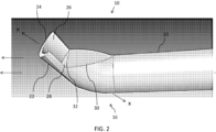
- FIG. 2 there is shown a close-up, side perspective view schematic representation of the distal end 16 of the cutting device 10, according to an embodiment.
- the narrowing portion 20 of the elongated shaft 12 extends to the distal end 16.
- the distal end 16 comprises a cutting tip 22, as shown in FIG. 2 .
- the cutting tip 22 extends along an x - x axis.
- the cutting tip 22 extends at angle relative to the central longitudinal y - y axis (which extends through the elongated shaft 12).
- the cutting tip 22 extends at an angle greater than 90 degrees relative to the central longitudinal y - y axis.
- the cutting tip 22 comprises a curved blade 24.
- the curved blade 24 has a semi-circular cross-section such that the curved blade 24 is crescent-shaped and open toward the proximal direction.
- the curved blade 24 comprises an inner wall 26 extending to a flat, semi-circular base 28. Further, the base 28 of the curved blade 24 extends to and abuts a flat portion 30 of the cutting tip 22. In the depicted embodiment, the flat portion 30 is D-shaped and extends proximally.
- the base 28 of the curved blade 24 and the flat portion 30 are connected at a flange 32 or edge.
- the base 28 extends at an angle relative to the flat portion 30.
- the flat portion 30 extends along both a plane and an axis (z - z axis) that are substantially parallel to the central longitudinal y - y axis, while the base 28 extends along a plane and axis that is transverse to both the central longitudinal y - y axis and the x - x axis.
- the base 28 extends along an axis which is substantially perpendicular to the x - x axis. The angular configuration and curvature of the cutting tip 22 is optimized for use in hand and wrist procedures.
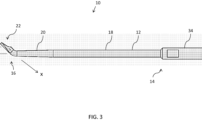
- FIG. 3 there is shown a side view schematic representation of a cutting device 10, according to an alternative embodiment.
- the proximal end 14 of the cutting device 10 comprises a handle 34 .
- the cutting device 10 can be manipulated directly by the user via the handle 34 (or otherwise at the proximal end 14 of the device 10).
- the embodiment of the cutting device 10 in FIG. 3 comprises an elongated shaft 12 extending along a central longitudinal y - y axis between a proximal end 14 and a distal end 16.
- the elongated shaft 12 may be cylindrical and have a uniform diameter or a varied diameter, as described above.
- the elongated shaft 12 of the cutting device 10 in FIG. 3 comprises a proximal portion 18 and a distal narrowing portion 20. As shown, the distal narrowing portion 20 is tapered in the distal direction. The distal narrowing portion 20 allows the cutting device 10 to access and cut small surgical areas, such as in the foot and ankle.
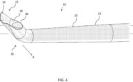
- the cutting tip 22 comprises a curved blade 24 which is open in the proximal direction.
- the curved blade 24 has a semi-circular cross-section such that the curved blade 24 is crescent-shaped.
- the curved blade 24 comprises an inner wall 26 extending to a base 28.
- the base 28 in the embodiment shown in FIG. 3-4 is sloped, extending toward the central longitudinal y - y axis (and elongated shaft 12). Further, the sloped base 28 of the curved blade 24 extends to and abuts a flat portion 30 of the cutting tip 22.
- the flat portion 30 is circular or semi-circular and extends proximally.
- the base 28 of the curved blade 24 slopes or extends to the flat portion 30 of the curved blade 24.
- the base 28 also extends at least partially around the flat portion 30, as shown in FIG. 4 .
- the flat portion 30 extends along a plane and a z - z axis, which are substantially parallel to the central longitudinal y - y axis, as shown in FIG. 3 .
- the angular configuration and curvature of the cutting tip 22 is optimized for use in foot and ankle procedures.
- an element of a device that "comprises”, “has”, “includes” or “contains” one or more features possesses those one or more features, but is not limited to possessing only those one or more features.
- a device or structure that is configured in a certain way is configured in at least that way, but may also be configured in ways that are not listed.
Landscapes
- Health & Medical Sciences (AREA)
- Surgery (AREA)
- Life Sciences & Earth Sciences (AREA)
- Medical Informatics (AREA)
- Animal Behavior & Ethology (AREA)
- Engineering & Computer Science (AREA)
- Biomedical Technology (AREA)
- Heart & Thoracic Surgery (AREA)
- Veterinary Medicine (AREA)
- Molecular Biology (AREA)
- Nuclear Medicine, Radiotherapy & Molecular Imaging (AREA)
- General Health & Medical Sciences (AREA)
- Public Health (AREA)
- Dentistry (AREA)
- Oral & Maxillofacial Surgery (AREA)
- Orthopedic Medicine & Surgery (AREA)
- Vascular Medicine (AREA)
- Surgical Instruments (AREA)
Claims (13)
- Chirurgische Schneidvorrichtung (10), umfassend:einen länglichen Schaft (12) mit einem proximalen Abschnitt (18) und einem distalen Abschnitt (20), die zwischen einem proximalen Ende (14) und einem distalen Ende (16) verbunden sind;eine zentrale Längsachse (y-y), die durch den länglichen Schaft (12) verläuft;wobei der proximale Abschnitt (18) einen ersten Durchmesser und der distale Abschnitt (20) einen zweiten Durchmesser aufweist, wobei der erste Durchmesser größer als der zweite Durchmesser ist;eine Schneidspitze (22) an dem distalen Ende (16) des länglichen Schafts (12), die sich entlang einer zweiten Achse (x-x) unter einem Winkel relativ zur zentralen Längsachse (y-y) erstreckt;wobei die Schneidspitze (22) eine gebogene Klinge (24) umfasst, die in einer proximalen Richtung offen ist;wobei die gebogene Klinge (24) eine Innenwand (26) umfasst, die sich zu einer Basis (28) der Schneidspitze (22) erstreckt,dadurch gekennzeichnet, dass ein Querschnitt der gebogenen Klinge (24) in einer Ebene senkrecht zur zweiten Achse (x-x) sichelförmig ist und die Basis (28) halbkreisförmig ist.
- Vorrichtung (10) nach Anspruch 1, wobei sich der distale Abschnitt (20) verjüngt und sein Durchmesser in einer distalen Richtung abnimmt.
- Vorrichtung (10) nach Anspruch 1, wobei der Winkel, in dem sich die Schneidspitze (22) relativ zur zentralen Längsachse (y-y) erstreckt, größer als 90 Grad ist.
- Vorrichtung (10) nach Anspruch 1, ferner umfassend einen flachen Abschnitt (30) an der Schneidspitze (22), wobei der flache Abschnitt (30) mit der gebogenen Klinge (24) verbunden ist und sich in eine proximale Richtung erstreckt.
- Vorrichtung (10) nach Anspruch 4, wobei sich der flache Abschnitt (30) entlang einer Ebene erstreckt, die im Wesentlichen parallel zu der zentralen Längsachse (y-y) liegt.
- Vorrichtung (10) nach Anspruch 1, wobei sich die Basis (28) entlang einer Ebene erstreckt, die im Wesentlichen senkrecht zur zweiten Achse (x-x) ist.
- Vorrichtung (10) nach Anspruch 1, ferner umfassend einen flachen Abschnitt (30), der mit der Basis (28) der Schneidspitze (22) durch einen Flansch (32) verbunden ist.
- Vorrichtung (10) nach Anspruch 7, wobei der flache Abschnitt (30) D-förmig ist.
- Vorrichtung (10) nach Anspruch 1, ferner umfassend einen Griff (34), der am proximalen Ende (14) des länglichen Schafts (12) angebracht ist.
- Vorrichtung (10) nach Anspruch 9, wobei die Basis (28) in Richtung des länglichen Schafts (12) geneigt ist.
- Vorrichtung (10) nach Anspruch 9, ferner umfassend einen flachen Abschnitt, wobei sich die Basis (28) bis zum flachen Abschnitt (30) der Schneidspitze (22) und zumindest teilweise um diesen herum erstreckt.
- Vorrichtung (10) nach Anspruch 11, wobei der flache Abschnitt (30) kreisförmig oder halbkreisförmig ist.
- Vorrichtung nach Anspruch 7 oder 11, wobei sich der flache Abschnitt (30) in einer proximalen Richtung entlang einer dritten Achse (z-z) erstreckt, die im Wesentlichen parallel zur zentralen Längsachse (y-y) ist.
Applications Claiming Priority (2)
| Application Number | Priority Date | Filing Date | Title |
|---|---|---|---|
| US201862735290P | 2018-09-24 | 2018-09-24 | |
| PCT/US2019/052550 WO2020068718A2 (en) | 2018-09-24 | 2019-09-24 | Chondrotome |
Publications (2)
| Publication Number | Publication Date |
|---|---|
| EP3856048A2 EP3856048A2 (de) | 2021-08-04 |
| EP3856048B1 true EP3856048B1 (de) | 2025-04-09 |
Family
ID=68240806
Family Applications (1)
| Application Number | Title | Priority Date | Filing Date |
|---|---|---|---|
| EP19787126.2A Active EP3856048B1 (de) | 2018-09-24 | 2019-09-24 | Chondrotom |
Country Status (9)
| Country | Link |
|---|---|
| US (1) | US20220031348A1 (de) |
| EP (1) | EP3856048B1 (de) |
| JP (2) | JP7763660B2 (de) |
| KR (2) | KR102827412B1 (de) |
| CN (1) | CN112888383B (de) |
| AU (1) | AU2019347729B2 (de) |
| CA (1) | CA3111879C (de) |
| ES (1) | ES3032291T3 (de) |
| WO (1) | WO2020068718A2 (de) |
Families Citing this family (2)
| Publication number | Priority date | Publication date | Assignee | Title |
|---|---|---|---|---|
| CN114601553B (zh) * | 2022-04-12 | 2024-08-16 | 中国人民解放军陆军军医大学第一附属医院 | 半月板前角切割器 |
| US12414785B1 (en) | 2025-03-17 | 2025-09-16 | Avantec Vascular Corporation | Cutters with pulsating vacuum control |
Family Cites Families (16)
| Publication number | Priority date | Publication date | Assignee | Title |
|---|---|---|---|---|
| DE865784C (de) * | 1951-07-18 | 1953-02-05 | Heinz Dr Beck | Spiegelraspatorium |
| NL106732C (de) * | 1955-03-08 | |||
| JPH0529697Y2 (de) * | 1988-12-07 | 1993-07-29 | ||
| US5586989A (en) * | 1995-01-27 | 1996-12-24 | Bray, Jr.; Robert | Microsurgical curette |
| US6387110B1 (en) * | 1999-06-23 | 2002-05-14 | Smith & Nephew, Inc. | Coating for surgical blades |
| US8092475B2 (en) | 2005-04-15 | 2012-01-10 | Integra Lifesciences (Ireland) Ltd. | Ultrasonic horn for removal of hard tissue |
| JP2007135945A (ja) * | 2005-11-21 | 2007-06-07 | Kazuko Kawaguchi | 抜歯工具 |
| FR2937239B1 (fr) | 2008-10-17 | 2010-11-26 | Fournitures Hospitalieres Ind | Dispositif chirurgical, notamment pour la chirurgie du pied |
| US8287485B2 (en) * | 2009-01-28 | 2012-10-16 | Olympus Medical Systems Corp. | Treatment system for surgery and control method of treatment system for surgery |
| EP2517669A4 (de) * | 2009-12-21 | 2017-10-25 | Nishikibe Seisakusho Co., Ltd | Schleifspan |
| US8951272B2 (en) * | 2010-02-11 | 2015-02-10 | Ethicon Endo-Surgery, Inc. | Seal arrangements for ultrasonically powered surgical instruments |
| US8894673B2 (en) * | 2011-10-07 | 2014-11-25 | Misonix, Incorporated | Ultrasonic osteotome |
| US9192390B2 (en) * | 2012-12-14 | 2015-11-24 | DePuy Synthes Products, Inc. | Surgical saw blade |
| US20140276848A1 (en) * | 2013-03-13 | 2014-09-18 | Roy Leguidleguid | Tissue modification devices |
| US20160015415A1 (en) * | 2014-07-17 | 2016-01-21 | Spineology Inc. | Articulating tissue dissector |
| US10123810B2 (en) * | 2015-09-02 | 2018-11-13 | Life Spine, Inc. | Medical instrument set and method of use for treating bony aberrations of the calcaneus |
-
2019
- 2019-09-24 CA CA3111879A patent/CA3111879C/en active Active
- 2019-09-24 KR KR1020237042261A patent/KR102827412B1/ko active Active
- 2019-09-24 AU AU2019347729A patent/AU2019347729B2/en active Active
- 2019-09-24 KR KR1020217008269A patent/KR20210047325A/ko not_active Ceased
- 2019-09-24 JP JP2021516399A patent/JP7763660B2/ja active Active
- 2019-09-24 EP EP19787126.2A patent/EP3856048B1/de active Active
- 2019-09-24 US US17/278,753 patent/US20220031348A1/en active Pending
- 2019-09-24 WO PCT/US2019/052550 patent/WO2020068718A2/en not_active Ceased
- 2019-09-24 ES ES19787126T patent/ES3032291T3/es active Active
- 2019-09-24 CN CN201980066493.XA patent/CN112888383B/zh active Active
-
2024
- 2024-10-09 JP JP2024176879A patent/JP2025004172A/ja active Pending
Also Published As
| Publication number | Publication date |
|---|---|
| KR20210047325A (ko) | 2021-04-29 |
| CN112888383A (zh) | 2021-06-01 |
| US20220031348A1 (en) | 2022-02-03 |
| CA3111879C (en) | 2023-10-17 |
| WO2020068718A2 (en) | 2020-04-02 |
| KR102827412B1 (ko) | 2025-07-01 |
| ES3032291T3 (en) | 2025-07-16 |
| EP3856048A2 (de) | 2021-08-04 |
| CA3111879A1 (en) | 2020-04-02 |
| JP2022500186A (ja) | 2022-01-04 |
| CN112888383B (zh) | 2026-03-03 |
| AU2019347729B2 (en) | 2022-06-30 |
| WO2020068718A3 (en) | 2020-05-07 |
| KR20230170983A (ko) | 2023-12-19 |
| JP2025004172A (ja) | 2025-01-14 |
| AU2019347729A1 (en) | 2021-04-01 |
| JP7763660B2 (ja) | 2025-11-04 |
Similar Documents
| Publication | Publication Date | Title |
|---|---|---|
| JP4832522B2 (ja) | 低侵襲の関節全置換のための装置および方法 | |
| US8529568B2 (en) | Surgical cutting tool | |
| US9763673B2 (en) | Osteotome | |
| US4995875A (en) | Femoral elevating tool | |
| JPH0529698Y2 (de) | ||
| US20040153084A1 (en) | Resection guide alignment apparatus | |
| EP1832239A1 (de) | Einweg-Resektionsführung | |
| US20100168799A1 (en) | Ulnar osteotomy plate including increased compression | |
| US11559313B2 (en) | Radial saw blade and hub for osteotomy | |
| JP2025004172A (ja) | 外科手術切断装置 | |
| US9522007B2 (en) | Orthopedic saw blade | |
| CN209301235U (zh) | 一种截骨手术限位装置及骨凿装置 | |
| CN110151251B (zh) | 一种髁间截骨钻 | |
| CN117835922A (zh) | 改进的外科手术摆动锯片 | |
| RU2779066C1 (ru) | Набор инструментов для адаптации сочленяющихся поверхностей в дефекте длинных трубчатых костей | |
| Gariepy | Knee Surgery |
Legal Events
| Date | Code | Title | Description |
|---|---|---|---|
| STAA | Information on the status of an ep patent application or granted ep patent |
Free format text: STATUS: UNKNOWN |
|
| STAA | Information on the status of an ep patent application or granted ep patent |
Free format text: STATUS: THE INTERNATIONAL PUBLICATION HAS BEEN MADE |
|
| PUAI | Public reference made under article 153(3) epc to a published international application that has entered the european phase |
Free format text: ORIGINAL CODE: 0009012 |
|
| STAA | Information on the status of an ep patent application or granted ep patent |
Free format text: STATUS: REQUEST FOR EXAMINATION WAS MADE |
|
| 17P | Request for examination filed |
Effective date: 20210308 |
|
| AK | Designated contracting states |
Kind code of ref document: A2 Designated state(s): AL AT BE BG CH CY CZ DE DK EE ES FI FR GB GR HR HU IE IS IT LI LT LU LV MC MK MT NL NO PL PT RO RS SE SI SK SM TR |
|
| DAV | Request for validation of the european patent (deleted) | ||
| DAX | Request for extension of the european patent (deleted) | ||
| P01 | Opt-out of the competence of the unified patent court (upc) registered |
Effective date: 20230526 |
|
| GRAP | Despatch of communication of intention to grant a patent |
Free format text: ORIGINAL CODE: EPIDOSNIGR1 |
|
| STAA | Information on the status of an ep patent application or granted ep patent |
Free format text: STATUS: GRANT OF PATENT IS INTENDED |
|
| INTG | Intention to grant announced |
Effective date: 20241129 |
|
| GRAS | Grant fee paid |
Free format text: ORIGINAL CODE: EPIDOSNIGR3 |
|
| GRAA | (expected) grant |
Free format text: ORIGINAL CODE: 0009210 |
|
| STAA | Information on the status of an ep patent application or granted ep patent |
Free format text: STATUS: THE PATENT HAS BEEN GRANTED |
|
| RAP3 | Party data changed (applicant data changed or rights of an application transferred) |
Owner name: CONMED CORPORATION |
|
| AK | Designated contracting states |
Kind code of ref document: B1 Designated state(s): AL AT BE BG CH CY CZ DE DK EE ES FI FR GB GR HR HU IE IS IT LI LT LU LV MC MK MT NL NO PL PT RO RS SE SI SK SM TR |
|
| REG | Reference to a national code |
Ref country code: GB Ref legal event code: FG4D |
|
| REG | Reference to a national code |
Ref country code: CH Ref legal event code: EP |
|
| REG | Reference to a national code |
Ref country code: IE Ref legal event code: FG4D |
|
| REG | Reference to a national code |
Ref country code: DE Ref legal event code: R096 Ref document number: 602019068454 Country of ref document: DE |
|
| REG | Reference to a national code |
Ref country code: ES Ref legal event code: FG2A Ref document number: 3032291 Country of ref document: ES Kind code of ref document: T3 Effective date: 20250716 |
|
| REG | Reference to a national code |
Ref country code: NL Ref legal event code: MP Effective date: 20250409 |
|
| PG25 | Lapsed in a contracting state [announced via postgrant information from national office to epo] |
Ref country code: NL Free format text: LAPSE BECAUSE OF FAILURE TO SUBMIT A TRANSLATION OF THE DESCRIPTION OR TO PAY THE FEE WITHIN THE PRESCRIBED TIME-LIMIT Effective date: 20250409 |
|
| REG | Reference to a national code |
Ref country code: AT Ref legal event code: MK05 Ref document number: 1782809 Country of ref document: AT Kind code of ref document: T Effective date: 20250409 |
|
| PG25 | Lapsed in a contracting state [announced via postgrant information from national office to epo] |
Ref country code: FI Free format text: LAPSE BECAUSE OF FAILURE TO SUBMIT A TRANSLATION OF THE DESCRIPTION OR TO PAY THE FEE WITHIN THE PRESCRIBED TIME-LIMIT Effective date: 20250409 Ref country code: PT Free format text: LAPSE BECAUSE OF FAILURE TO SUBMIT A TRANSLATION OF THE DESCRIPTION OR TO PAY THE FEE WITHIN THE PRESCRIBED TIME-LIMIT Effective date: 20250811 |
|
| PGFP | Annual fee paid to national office [announced via postgrant information from national office to epo] |
Ref country code: DE Payment date: 20250827 Year of fee payment: 7 |
|
| REG | Reference to a national code |
Ref country code: LT Ref legal event code: MG9D |
|
| PG25 | Lapsed in a contracting state [announced via postgrant information from national office to epo] |
Ref country code: GR Free format text: LAPSE BECAUSE OF FAILURE TO SUBMIT A TRANSLATION OF THE DESCRIPTION OR TO PAY THE FEE WITHIN THE PRESCRIBED TIME-LIMIT Effective date: 20250710 Ref country code: NO Free format text: LAPSE BECAUSE OF FAILURE TO SUBMIT A TRANSLATION OF THE DESCRIPTION OR TO PAY THE FEE WITHIN THE PRESCRIBED TIME-LIMIT Effective date: 20250709 |
|
| PG25 | Lapsed in a contracting state [announced via postgrant information from national office to epo] |
Ref country code: PL Free format text: LAPSE BECAUSE OF FAILURE TO SUBMIT A TRANSLATION OF THE DESCRIPTION OR TO PAY THE FEE WITHIN THE PRESCRIBED TIME-LIMIT Effective date: 20250409 |
|
| PGFP | Annual fee paid to national office [announced via postgrant information from national office to epo] |
Ref country code: IT Payment date: 20250827 Year of fee payment: 7 |
|
| PG25 | Lapsed in a contracting state [announced via postgrant information from national office to epo] |
Ref country code: BG Free format text: LAPSE BECAUSE OF FAILURE TO SUBMIT A TRANSLATION OF THE DESCRIPTION OR TO PAY THE FEE WITHIN THE PRESCRIBED TIME-LIMIT Effective date: 20250409 |
|
| PGFP | Annual fee paid to national office [announced via postgrant information from national office to epo] |
Ref country code: GB Payment date: 20250821 Year of fee payment: 7 |
|
| PG25 | Lapsed in a contracting state [announced via postgrant information from national office to epo] |
Ref country code: HR Free format text: LAPSE BECAUSE OF FAILURE TO SUBMIT A TRANSLATION OF THE DESCRIPTION OR TO PAY THE FEE WITHIN THE PRESCRIBED TIME-LIMIT Effective date: 20250409 |
|
| PG25 | Lapsed in a contracting state [announced via postgrant information from national office to epo] |
Ref country code: AT Free format text: LAPSE BECAUSE OF FAILURE TO SUBMIT A TRANSLATION OF THE DESCRIPTION OR TO PAY THE FEE WITHIN THE PRESCRIBED TIME-LIMIT Effective date: 20250409 |
|
| PGFP | Annual fee paid to national office [announced via postgrant information from national office to epo] |
Ref country code: FR Payment date: 20250821 Year of fee payment: 7 |
|
| PG25 | Lapsed in a contracting state [announced via postgrant information from national office to epo] |
Ref country code: RS Free format text: LAPSE BECAUSE OF FAILURE TO SUBMIT A TRANSLATION OF THE DESCRIPTION OR TO PAY THE FEE WITHIN THE PRESCRIBED TIME-LIMIT Effective date: 20250709 |
|
| PG25 | Lapsed in a contracting state [announced via postgrant information from national office to epo] |
Ref country code: IS Free format text: LAPSE BECAUSE OF FAILURE TO SUBMIT A TRANSLATION OF THE DESCRIPTION OR TO PAY THE FEE WITHIN THE PRESCRIBED TIME-LIMIT Effective date: 20250809 |
|
| PG25 | Lapsed in a contracting state [announced via postgrant information from national office to epo] |
Ref country code: LV Free format text: LAPSE BECAUSE OF FAILURE TO SUBMIT A TRANSLATION OF THE DESCRIPTION OR TO PAY THE FEE WITHIN THE PRESCRIBED TIME-LIMIT Effective date: 20250409 |
|
| REG | Reference to a national code |
Ref country code: DE Ref legal event code: R097 Ref document number: 602019068454 Country of ref document: DE |
|
| PG25 | Lapsed in a contracting state [announced via postgrant information from national office to epo] |
Ref country code: SM Free format text: LAPSE BECAUSE OF FAILURE TO SUBMIT A TRANSLATION OF THE DESCRIPTION OR TO PAY THE FEE WITHIN THE PRESCRIBED TIME-LIMIT Effective date: 20250409 Ref country code: DK Free format text: LAPSE BECAUSE OF FAILURE TO SUBMIT A TRANSLATION OF THE DESCRIPTION OR TO PAY THE FEE WITHIN THE PRESCRIBED TIME-LIMIT Effective date: 20250409 |
|
| PG25 | Lapsed in a contracting state [announced via postgrant information from national office to epo] |
Ref country code: CZ Free format text: LAPSE BECAUSE OF FAILURE TO SUBMIT A TRANSLATION OF THE DESCRIPTION OR TO PAY THE FEE WITHIN THE PRESCRIBED TIME-LIMIT Effective date: 20250409 |
|
| PG25 | Lapsed in a contracting state [announced via postgrant information from national office to epo] |
Ref country code: EE Free format text: LAPSE BECAUSE OF FAILURE TO SUBMIT A TRANSLATION OF THE DESCRIPTION OR TO PAY THE FEE WITHIN THE PRESCRIBED TIME-LIMIT Effective date: 20250409 |
|
| PG25 | Lapsed in a contracting state [announced via postgrant information from national office to epo] |
Ref country code: SK Free format text: LAPSE BECAUSE OF FAILURE TO SUBMIT A TRANSLATION OF THE DESCRIPTION OR TO PAY THE FEE WITHIN THE PRESCRIBED TIME-LIMIT Effective date: 20250409 Ref country code: RO Free format text: LAPSE BECAUSE OF FAILURE TO SUBMIT A TRANSLATION OF THE DESCRIPTION OR TO PAY THE FEE WITHIN THE PRESCRIBED TIME-LIMIT Effective date: 20250409 |
|
| PGFP | Annual fee paid to national office [announced via postgrant information from national office to epo] |
Ref country code: ES Payment date: 20251017 Year of fee payment: 7 |
|
| PLBE | No opposition filed within time limit |
Free format text: ORIGINAL CODE: 0009261 |
|
| STAA | Information on the status of an ep patent application or granted ep patent |
Free format text: STATUS: NO OPPOSITION FILED WITHIN TIME LIMIT |
|
| REG | Reference to a national code |
Ref country code: CH Ref legal event code: L10 Free format text: ST27 STATUS EVENT CODE: U-0-0-L10-L00 (AS PROVIDED BY THE NATIONAL OFFICE) Effective date: 20260218 |
|
| 26N | No opposition filed |
Effective date: 20260112 |