EP3856024B1 - Auswertung von impedanzmessungen - Google Patents
Auswertung von impedanzmessungen Download PDFInfo
- Publication number
- EP3856024B1 EP3856024B1 EP19866489.8A EP19866489A EP3856024B1 EP 3856024 B1 EP3856024 B1 EP 3856024B1 EP 19866489 A EP19866489 A EP 19866489A EP 3856024 B1 EP3856024 B1 EP 3856024B1
- Authority
- EP
- European Patent Office
- Prior art keywords
- impedance
- measurement
- values
- processing devices
- curve
- Prior art date
- Legal status (The legal status is an assumption and is not a legal conclusion. Google has not performed a legal analysis and makes no representation as to the accuracy of the status listed.)
- Active
Links
Images


Classifications
-
- A—HUMAN NECESSITIES
- A61—MEDICAL OR VETERINARY SCIENCE; HYGIENE
- A61B—DIAGNOSIS; SURGERY; IDENTIFICATION
- A61B5/00—Measuring for diagnostic purposes; Identification of persons
- A61B5/05—Detecting, measuring or recording for diagnosis by means of electric currents or magnetic fields; Measuring using microwaves or radio waves
- A61B5/053—Measuring electrical impedance or conductance of a portion of the body
- A61B5/0537—Measuring body composition by impedance, e.g. tissue hydration or fat content
-
- A—HUMAN NECESSITIES
- A61—MEDICAL OR VETERINARY SCIENCE; HYGIENE
- A61B—DIAGNOSIS; SURGERY; IDENTIFICATION
- A61B5/00—Measuring for diagnostic purposes; Identification of persons
- A61B5/48—Other medical applications
- A61B5/4869—Determining body composition
-
- A—HUMAN NECESSITIES
- A61—MEDICAL OR VETERINARY SCIENCE; HYGIENE
- A61B—DIAGNOSIS; SURGERY; IDENTIFICATION
- A61B5/00—Measuring for diagnostic purposes; Identification of persons
- A61B5/68—Arrangements of detecting, measuring or recording means, e.g. sensors, in relation to patient
- A61B5/6887—Arrangements of detecting, measuring or recording means, e.g. sensors, in relation to patient mounted on external non-worn devices, e.g. non-medical devices
-
- A—HUMAN NECESSITIES
- A61—MEDICAL OR VETERINARY SCIENCE; HYGIENE
- A61B—DIAGNOSIS; SURGERY; IDENTIFICATION
- A61B5/00—Measuring for diagnostic purposes; Identification of persons
- A61B5/72—Signal processing specially adapted for physiological signals or for diagnostic purposes
- A61B5/7221—Determining signal validity, reliability or quality
-
- A—HUMAN NECESSITIES
- A61—MEDICAL OR VETERINARY SCIENCE; HYGIENE
- A61B—DIAGNOSIS; SURGERY; IDENTIFICATION
- A61B5/00—Measuring for diagnostic purposes; Identification of persons
- A61B5/72—Signal processing specially adapted for physiological signals or for diagnostic purposes
- A61B5/7235—Details of waveform analysis
- A61B5/7253—Details of waveform analysis characterised by using transforms
-
- A—HUMAN NECESSITIES
- A61—MEDICAL OR VETERINARY SCIENCE; HYGIENE
- A61B—DIAGNOSIS; SURGERY; IDENTIFICATION
- A61B5/00—Measuring for diagnostic purposes; Identification of persons
- A61B5/0002—Remote monitoring of patients using telemetry, e.g. transmission of vital signals via a communication network
- A61B5/0004—Remote monitoring of patients using telemetry, e.g. transmission of vital signals via a communication network characterised by the type of physiological signal transmitted
-
- A—HUMAN NECESSITIES
- A61—MEDICAL OR VETERINARY SCIENCE; HYGIENE
- A61B—DIAGNOSIS; SURGERY; IDENTIFICATION
- A61B5/00—Measuring for diagnostic purposes; Identification of persons
- A61B5/0002—Remote monitoring of patients using telemetry, e.g. transmission of vital signals via a communication network
- A61B5/0015—Remote monitoring of patients using telemetry, e.g. transmission of vital signals via a communication network characterised by features of the telemetry system
- A61B5/002—Monitoring the patient using a local or closed circuit, e.g. in a room or building
-
- A—HUMAN NECESSITIES
- A61—MEDICAL OR VETERINARY SCIENCE; HYGIENE
- A61B—DIAGNOSIS; SURGERY; IDENTIFICATION
- A61B5/00—Measuring for diagnostic purposes; Identification of persons
- A61B5/0002—Remote monitoring of patients using telemetry, e.g. transmission of vital signals via a communication network
- A61B5/0015—Remote monitoring of patients using telemetry, e.g. transmission of vital signals via a communication network characterised by features of the telemetry system
- A61B5/0022—Monitoring a patient using a global network, e.g. telephone networks, internet
-
- A—HUMAN NECESSITIES
- A61—MEDICAL OR VETERINARY SCIENCE; HYGIENE
- A61B—DIAGNOSIS; SURGERY; IDENTIFICATION
- A61B5/00—Measuring for diagnostic purposes; Identification of persons
- A61B5/0059—Measuring for diagnostic purposes; Identification of persons using light, e.g. diagnosis by transillumination, diascopy, fluorescence
- A61B5/0062—Arrangements for scanning
- A61B5/0064—Body surface scanning
-
- A—HUMAN NECESSITIES
- A61—MEDICAL OR VETERINARY SCIENCE; HYGIENE
- A61B—DIAGNOSIS; SURGERY; IDENTIFICATION
- A61B5/00—Measuring for diagnostic purposes; Identification of persons
- A61B5/02—Detecting, measuring or recording for evaluating the cardiovascular system, e.g. pulse, heart rate, blood pressure or blood flow
- A61B5/0205—Simultaneously evaluating both cardiovascular conditions and different types of body conditions, e.g. heart and respiratory condition
-
- A—HUMAN NECESSITIES
- A61—MEDICAL OR VETERINARY SCIENCE; HYGIENE
- A61B—DIAGNOSIS; SURGERY; IDENTIFICATION
- A61B5/00—Measuring for diagnostic purposes; Identification of persons
- A61B5/02—Detecting, measuring or recording for evaluating the cardiovascular system, e.g. pulse, heart rate, blood pressure or blood flow
- A61B5/021—Measuring pressure in heart or blood vessels
-
- A—HUMAN NECESSITIES
- A61—MEDICAL OR VETERINARY SCIENCE; HYGIENE
- A61B—DIAGNOSIS; SURGERY; IDENTIFICATION
- A61B5/00—Measuring for diagnostic purposes; Identification of persons
- A61B5/02—Detecting, measuring or recording for evaluating the cardiovascular system, e.g. pulse, heart rate, blood pressure or blood flow
- A61B5/024—Measuring pulse rate or heart rate
-
- A—HUMAN NECESSITIES
- A61—MEDICAL OR VETERINARY SCIENCE; HYGIENE
- A61B—DIAGNOSIS; SURGERY; IDENTIFICATION
- A61B5/00—Measuring for diagnostic purposes; Identification of persons
- A61B5/103—Measuring devices for testing the shape, pattern, colour, size or movement of the body or parts thereof, for diagnostic purposes
- A61B5/107—Measuring physical dimensions, e.g. size of the entire body or parts thereof
- A61B5/1079—Measuring physical dimensions, e.g. size of the entire body or parts thereof using optical or photographic means
-
- A—HUMAN NECESSITIES
- A61—MEDICAL OR VETERINARY SCIENCE; HYGIENE
- A61B—DIAGNOSIS; SURGERY; IDENTIFICATION
- A61B5/00—Measuring for diagnostic purposes; Identification of persons
- A61B5/48—Other medical applications
- A61B5/4869—Determining body composition
- A61B5/4872—Body fat
-
- A—HUMAN NECESSITIES
- A61—MEDICAL OR VETERINARY SCIENCE; HYGIENE
- A61B—DIAGNOSIS; SURGERY; IDENTIFICATION
- A61B5/00—Measuring for diagnostic purposes; Identification of persons
- A61B5/48—Other medical applications
- A61B5/4869—Determining body composition
- A61B5/4875—Hydration status, fluid retention of the body
- A61B5/4878—Evaluating oedema
-
- A—HUMAN NECESSITIES
- A61—MEDICAL OR VETERINARY SCIENCE; HYGIENE
- A61B—DIAGNOSIS; SURGERY; IDENTIFICATION
- A61B5/00—Measuring for diagnostic purposes; Identification of persons
- A61B5/72—Signal processing specially adapted for physiological signals or for diagnostic purposes
- A61B5/7235—Details of waveform analysis
- A61B5/7264—Classification of physiological signals or data, e.g. using neural networks, statistical classifiers, expert systems or fuzzy systems
- A61B5/7267—Classification of physiological signals or data, e.g. using neural networks, statistical classifiers, expert systems or fuzzy systems involving training the classification device
-
- A—HUMAN NECESSITIES
- A61—MEDICAL OR VETERINARY SCIENCE; HYGIENE
- A61B—DIAGNOSIS; SURGERY; IDENTIFICATION
- A61B5/00—Measuring for diagnostic purposes; Identification of persons
- A61B5/74—Details of notification to user or communication with user or patient; User input means
- A61B5/742—Details of notification to user or communication with user or patient; User input means using visual displays
-
- A—HUMAN NECESSITIES
- A61—MEDICAL OR VETERINARY SCIENCE; HYGIENE
- A61B—DIAGNOSIS; SURGERY; IDENTIFICATION
- A61B5/00—Measuring for diagnostic purposes; Identification of persons
- A61B5/74—Details of notification to user or communication with user or patient; User input means
- A61B5/7475—User input or interface means, e.g. keyboard, pointing device, joystick
Definitions
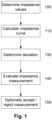
- the present invention relates to a method and system for performing impedance measurements and in particular to evaluating the impedance measurements, for example to confirm the impedance measurement is valid.
- One existing technique for determining biological indicators relating to a subject involves the use of bioelectrical impedance. This process typically involves using a measuring device to measure the electrical impedance of a subject's body using a series of electrodes placed on the skin surface, although other techniques could be used. Changes in electrical impedance are used to determine parameters, such as changes in fluid levels, associated with the cardiac cycle, oedema, or the like.
- Impedance measuring apparatus is sometimes sensitive to external factors, including stray capacitances between the subject and the local environment and the measurement apparatus, variations in electrode/tissue interface impedances, also known as electrode impedances, as well as stray capacitances and inductive coupling between the leads used to connect the measuring device to the electrodes, meaning measurements performed by an impedance measuring device are not always accurate.
- Measurements are typically evaluated manually by having user's view a visual representation of measured impedance values to see if these "look correct". Such a subjective assessment is difficult for inexperienced users to perform, meaning accurate measurements may be discarded, whilst inaccurate measurements are used, which can in turn can lead to incorrect calculation of biological indicators.
- US20170325711A1 discloses a method and apparatus for testing the plausibility of electric impedance measurement values. The measurement values are determined during the measurement of the bioimpedance of a person.
- US20180184941A1 discloses an apparatus for analysis of body composition and hydration status by detecting resistance of the human subject at zero and infinite frequency including a method for measuring indirectly extracellular water mass, intracellular water mass, lean body mass, and body fat mass.
- US20100168530A1 discloses a method for determining biological indicators, the method including, in a processing system causing at least one radiation attenuation measurement to be performed and determining at least one first biological indicator using determined radiation attenuation.
- US20100268110A1 discloses a method of monitoring mucosal injury due to hypoperfusion and ischemia in the critically ill.
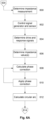
- an aspect of the present invention seeks to provide a system for performing a bioimpedance measurement on a biological subject as provided in claim 1.
- an aspect of the present invention seeks to provide a method for use in evaluating a bioimpedance measurement performed on a biological subject as provided in claim 15.
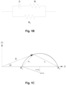
- the impedance curve is a circular segment.
- the impedance measurement is categorised as being at least one of: bad; questionable; and, acceptable.
- the co-variance matrix is generated based on a mean square error of the impedance curve and the impedance values.
- the one or more processing devices calculate an estimated error using a Jacobian transform.
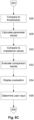
- the number of impedance parameter values include one or more of: R 0 which is the theoretical impedance at a frequency of OkHz; R inf which is the theoretical impedance at an infinite frequency; and, R i which is the intracellular impedance.
- the one or more processing devices evaluate the impedance measurement based on a number of negative reactance values.
- the one or more processing devices evaluate the impedance measurement as being: in a first category if: an R 0 error is greater than a first category R 0 threshold; in a second category if at least one of: an R i error is greater than a first category R i threshold; and, an R inf error is greater than a first category R inf threshold.
- the one or more processing devices apply a phase correction to impedance values measured at a frequency higher than a set frequency; and, calculate the impedance curve using the phase corrected impedance values.
- each impedance value includes a reactance value and a resistance value.
- the one or more processing devices determine a count of impedance values having negative reactance values; and, use the count to perform an evaluation of the impedance measurements.
- the one or more processing devices calculate an impedance parameter value using the impedance values; compare the impedance parameter value to a defined frequency impedance value, the defined frequency impedance value being determined from an impedance value obtained from impedance measurements performed at a defined measurement frequency; and, use a result of the comparison to perform an evaluation of the impedance measurements.
- the parameter value is R inf which is the theoretical impedance at an infinite frequency
- the defined frequency impedance value is determined from an impedance measurement performed at at least one of: greater than 100 kHz; greater than 500 kHz; less than 10000 kHz; less than 5000 kHz; less than 2000 kHz; between 500 kHz and 2000 kHz; and, about 1000 kHz.
- the parameter value is a theoretical impedance at the defined frequency.
- the measuring device includes a signal generator electrically connected to drive electrodes to apply drive signal to a user, a sensor electrically connected to sense electrodes to measure a response signal in the user and one or more processing devices that at least in part controls the signal general, receives an indication of a measured response signal from the sensor and calculates at least one measured impedance value.
- the term "subject” refers to any animal or animal tissue that is being assessed, and more particularly a human, although this is not intended to be limiting and the techniques could be applied more broadly to other vertebrates, mammals or tissues.
- R inf also referred to in literature as R ⁇
- R ⁇ is the impedance measured at the theoretical frequency of infinite kilohertz. Again, no such frequency current is achievable, but the complex impedance plot allows this to be used to extrapolate this value of impedance. This extrapolation is made possible because the frequencies measured to generate the plot allow the accurate determination of the radius of the circle. At infinite frequency, the current will not be affected by interaction with the cell membranes and will pass right through the cell membranes. Therefore, the impedance at R inf is the impedance due to both the extracellular and intracellular fluid, that is, the total body water. At this theoretical frequency the reactance component of impedance vector is also zero. This allows R ⁇ to be used with R 0 to derive an intracellular resistance R i , as well as other impedance parameters, such as X c , Z c or ⁇ .
- the impedance curve is typically a circular segment.
- other curves could be used in some situations.
- impedance measurements at higher frequencies can be inaccurate due to capacitive effects.
- This can be compensated using a phase correction procedure, as will be described in more detail below, which adjusts measured impedance values so that they more correctly align with the circular locus.
- a curve other than a circular locus could be used to account for high frequency effects.
- the use of a circle is particularly advantageous as this represents the idealised biological response and also simplifies the mathematics of evaluating the error, in turn reducing computational requirements for the one or more processing devices.
- the evaluation of the impedance measurements is typically used to help determine an impedance measurement validity. In one example, this is achieved by categorising the impedance measurement, for example, providing the measurement with a ranking, such as good, acceptable or bad, which may be denoted by a red, yellow or green, traffic light style indication.
- a ranking such as good, acceptable or bad, which may be denoted by a red, yellow or green, traffic light style indication.
- a ranking such as good, acceptable or bad
- a red, yellow or green, traffic light style indication such as presenting a "confidence of fit" score, such as a %, or the like, which is indicative of a degree of similarity and/or deviation between the impedance curve and the measured impedance values.
- Such indicators can then be used by an operator, to assist the operator in understanding whether the measurement is acceptable.
- the processing devices use the deviation to calculate an estimated error in impedance parameter values derived from the impedance curve and then use the estimated error to evaluate the impedance measurements.
- the assessment is performed to take into account that whilst the curve fit might not be particularly accurate, for example if some of the impedance values deviate significantly from the idealised curve, this might nevertheless still result in reasonably accurate parameter values. Accordingly, by estimating the error in the parameter values, this can be used to allow impedance measurements that would be rejected due to deviation alone to be accepted if the deviation does not affect the resulting parameter values. Similarly, this will allow some impedance measurements to be assessed as invalid even if the deviation is minimal, as long as the resulting impedance parameter values would be inaccurate. It will be appreciated that this improves the assessment of measurement validity, taking into account whether inaccuracies would have a material effect on the resulting calculated parameter values.
- the processing device calculates an error associated with each of a number of different impedance parameter values. This allows an assessment to be made of whether relevant parameter values are affected. For example, if the impedance measurements are made for assessing extra-cellular fluid levels only, inaccuracies in R inf might not be problematic, as long as R 0 is accurate.
- the processing devices can compare the estimated error to one or more thresholds and evaluate the impedance measurement based on results of the comparison.
- a threshold can be set to assess whether or not an error in the parameter value is meaningful or not, and hence whether the measurement should be considered as valid.
- thresholds might not be particularly accurate. For example, a measurement for an elderly patient having lymphedema may be quite different to a healthy teenager. Accordingly, in one example, thresholds are selected based on characteristics of the current subject, such as a similar age, height, weight, sex, medical symptoms or conditions, ethnicity, or the like. This can then be used to select thresholds derived from reference subjects having similar characteristics, making the thresholds relevant to the current subject.
- subject specific thresholds can be used.
- a custom threshold can be established for individual subjects to take into account that different subjects will respond differently to impedance measurements, so that a measurement that is unacceptable for one subject, might be acceptable for another subject.
- a good example of this is that subjects with dry skin typically have worse measurements than subjects with normally hydrated skin.
- the processing device can evaluate the impedance measurement using at least one threshold, determine a user assessment of the impedance measurement in accordance with user input commands and then selectively modify the at least one threshold based on the user assessment. For example, if a measurement is assessed to be unacceptable, but the user chooses to accept the measurement, the threshold could be adjusted to take this into account, allowing the system to become more effective over time.
- the processing devices calculate curve coefficients using the curve fitting algorithm and then determine the deviation using the curve coefficients and the impedance values. In one particular example, this is achieved using a method of least squares, with the deviation being determined based on a variance and/or co-variance between the impedance values and corresponding values from the curve.
- propagation of the error is achieved by determining the deviation by calculating a co-variance matrix indicative of variances and co-variances associated with the impedance curve and the impedance values and then using the co-variance matrix to estimate the error.
- An error is typically calculated for each of the impedance parameter values, allowing each error value to be compared to a respective threshold so that the evaluation can be performed based on results of the comparison. This is typically performed for at least R 0 , which is the theoretical impedance at a frequency of 0 kHz and R inf ; which is the theoretical impedance at an infinite frequency and may also be performed for R i , which is the intracellular impedance.
- measured reactances can have negative values, which is again indicative of an issue with the measurement.
- the processing devices can additionally and/or alternatively evaluate the impedance measurement based on a number of negative reactance values.
- the processing devices evaluate the impedance measurement as being in the first category if an R 0 error is greater than a first category R 0 threshold, or in a second category if an R i error is greater than a first category R i threshold or an R inf error is greater than a first category R inf threshold.
- machine learning can be used to analyse deviations, and an assessment of whether the deviations are acceptable, with this being used to develop a computational model that can perform assessments based on the deviation directly.
- the deviation could be assessed in a wide range of manners, and take into account a wide range of different factors, potentially leading to a more accurate assessment.
- phase correction can be applied to impedance values measured at a frequency higher than a set frequency, with the impedance curve being calculated using the phase corrected impedance values.
- the manner in which phase correction is performed is generally known and will be described in more detail below.
- evaluation of the impedance measurements can also be performed in accordance with other criteria.
- the processing device typically calculates an impedance parameter value using the impedance values, compares the impedance parameter value to a defined frequency impedance value, the defined frequency impedance value being determined from an impedance value obtained by from impedance measurements performed at a defined measurement frequency and then uses a result of the comparison to perform an evaluation of the impedance measurements.
- the parameter value could R 0 , which case the defined frequency impedance value is typically an impedance value measured at a low frequency, such as greater than 1 kHz, but less than less than 10 kHz, less than 20 kHz, or less than 30 kHz. In one example, the frequency is between 2 kHz and 4 kHz and is typically about 3 kHz.
- the difference thresholds could be absolute. For example, if the impedance parameter value is R 0 the first difference threshold could be 55 ⁇ , whereas the second difference threshold could be 35 ⁇ , whereas if the impedance parameter value is R inf the first difference threshold could be 70 ⁇ , whereas the second difference threshold could be 30 ⁇ .
- the difference thresholds could be relative, and may for example be set based on a percentage of the impedance parameter value.
- the impedance parameter value is R 0
- the first difference threshold could be 15%
- the second difference threshold could be 10%
- the impedance parameter value is R inf
- the second difference threshold could be 12%.
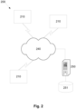
- the communications network 240 can be of any appropriate form, such as the Internet and/or a number of local area networks (LANs) and provides connectivity between the measuring systems 210 and the server 250. It will however be appreciated that this configuration is for the purpose of example only, and in practice the measuring systems 210 and server 250 can communicate via any appropriate mechanism, such as via wired or wireless connections, including, but not limited to mobile networks, private networks, such as an 802.11 network, the Internet, LANs, WANs, or the like, as well as via direct or point-to-point connections, such as Bluetooth, or the like.
- LANs local area networks
- the nature of the physical characteristic sensors 320 will vary depending on the characteristics to be measured, and could include for example scales for measuring an individual/subject's weight and/or an image capture device, such as a camera, body scanner, DEXA (Dual-Energy X-ray Absorptiometry), 3D laser or optical scanning, or the like, for measuring a height and/or body segment dimensions, as will be described in more detail below. Additionally or alternatively, this could include electronic scales for measuring a weight, and other monitoring equipment, for example for measuring heart rate, blood pressure or other characteristics.
- DEXA Direct-Energy X-ray Absorptiometry
- 3D laser or optical scanning or the like
- this could include electronic scales for measuring a weight, and other monitoring equipment, for example for measuring heart rate, blood pressure or other characteristics.
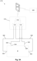
- the impedance measuring device 310 typically includes a measuring device processor 312 coupled to at least one signal generator 313 and at least one sensor 314, which are in turn coupled to respective drive and sense electrodes 323 and 324, via leads 322.
- the signal generator 313 generates a drive signal, which is applied to the individual/subject S via the drive electrodes 323, whilst the sensor 314 measures a response signal via the sense electrodes 324.
- the measuring device processor 312 controls the at least one signal generator 313 and the at least one sensor 314, allowing the impedance measurements to be performed.
- impedance parameter values such as values of R0, Zc, R ⁇ , which correspond to the impedance at zero, characteristic and infinite frequencies. These can in turn be used to determine information regarding both intracellular and extracellular fluid levels, as will be described in more detail below.
- the measuring device 310 may either apply an alternating signal at a single frequency, at a plurality of frequencies simultaneously, or a number of alternating signals at different frequencies sequentially, depending on the preferred implementation.
- the frequency or frequency range of the applied signals may also depend on the analysis being performed.
- electrode configurations similar to those described above with respect to Figures 3C to 3G can be achieved by selectively using respective ones of the drive and sense electrodes 323.1, 324.1, 323.2, 324.2.
- the client device 330 is in communication with the measuring device processor 312, typically via a wireless communications channels, such as Bluetooth or the like.
- the client device 330 is provided in a stand, which is then attached to mounting 327, allowing the client device 330 to be supported on the apparatus in use. This allows the client device 330 to act as a user interface, allowing operation of the impedance measuring device to be controlled, and allowing results of impedance measurements to be displayed.
- the client device 330 can also combine impedance values or indicators with information regarding indications of heart failure states and physical characteristics determined either by manual user input or based on signals from one or more physical characteristic sensors. This allows the client device to generate the reference data, which is then transferred via the communications network 240 to the server 250. However, alternatively, the server 250 could obtain the indication of heart failure states and/or physical characteristic from other data sources, depending on the preferred implementation.
- the client device 330 may be formed from any suitable processing system, such as a suitably programmed PC, Internet terminal, lap-top, or hand-held PC, and in one preferred example is either a tablet, or smart phone, or the like.
- the client device 330 is a standard processing system such as an Intel Architecture based processing system, which executes software applications stored on non-volatile (e.g., hard disk) storage, although this is not essential.
- the client devices 330 can be any electronic processing device such as a microprocessor, microchip processor, logic gate configuration, firmware optionally associated with implementing logic such as an FPGA (Field Programmable Gate Array), or any other electronic device, system or arrangement.
- the server includes at least one microprocessor 500, a memory 501, an optional input/output device 502, such as a keyboard and/or display, and an external interface 503, interconnected via a bus 504 as shown.
- the external interface 503 can be utilised for connecting the server 250 to peripheral devices, such as the communications networks 240, databases 251, other storage devices, or the like.
- peripheral devices such as the communications networks 240, databases 251, other storage devices, or the like.
- a single external interface 503 is shown, this is for the purpose of example only, and in practice multiple interfaces using various methods (eg. Ethernet, serial, USB, wireless or the like) may be provided.
- server 250 Whilst the server 250 is a shown as a single entity, it will be appreciated that the server 250 can be distributed over a number of geographically separate locations, for example by using processing systems and/or databases 251 that are provided as part of a cloud based environment. Thus, the above described arrangement is not essential and other suitable configurations could be used.
- the first and second electrodes 323, 324 are provided in contact with the subject to allow one or more signals to be injected into the subject S, and allowing a response signal to be measured.
- the location of the electrodes 323, 324 will depend on the segment of the subject S under study.
- the electrodes 323, 324 can be placed on the thoracic and neck region of the subject S to allow the impedance of the chest cavity to be determined.
- positioning electrodes on the wrist and ankles of a subject allows the impedance of limbs, torso and/or the entire body to be determined.
- the general arrangement is to provide electrodes on the hand at the base of the knuckles and between the bony protuberances of the wrist, and on the feet at the base of the toes and at the front of the ankle.
- the response signal will be a superposition of voltages generated by the human body, such as the ECG (electrocardiogram), voltages generated by the applied signal, and other signals caused by environmental electromagnetic interference. Accordingly, filtering or other suitable analysis may be employed to remove unwanted components.
- the acquired signal is typically demodulated to obtain the impedance of the system at the applied frequencies.
- One suitable method for demodulation of superposed frequencies is to use a Fast Fourier Transform (FFT) algorithm to transform the time domain data to the frequency domain. This is typically used when the applied current signal is a superposition of applied frequencies.
- FFT Fast Fourier Transform
- Another technique not requiring windowing of the measured signal is a sliding window FFT.
- the applied current signals are formed from a sweep of different frequencies
- a signal processing technique such as multiplying the measured signal with a reference sine wave and cosine wave derived from the signal generator, or with measured sine and cosine waves, and integrating over a whole number of cycles.
- This process known variously as quadrature demodulation or synchronous detection, rejects all uncorrelated or asynchronous signals and significantly reduces random noise.
- the drive and response signals are used to determine impedance values. This can be performed by the measuring device 310 alone, or can be performed in conjunction with the client device 330, for example by transferring measured current and voltage signals to the client device 330, which then analyses these to determine the measured impedances.
- impedance or admittance measurements are determined from the signals at each frequency by comparing the recorded voltage and the current through the subject.
- the demodulation algorithm can then produce amplitude and phase signals at each frequency, allowing an impedance value at each frequency to be determined.
- the above described process can be performed multiple times, for example to allow impedance measurements to be determined for multiple body segments, including the torso and one or more other segments, such as limbs. Additionally or alternatively, the process may be performed multiple times for the same body segment, with an average (or other statistical measure, such as median, mode, or the like) of two or more measurements being determined and, for example, used for further analysis.
- a phase correction is typically determined.
- BIS measurements on human subjects do not usually show the clean circular arc predicted by the complex impedance model, for a number of reasons including electrical contact issues, subject movement and so on, some of which can be addressed by good measurement procedures.
- one source of error which is difficult to avoid is capacitive leakage, which is especially prevalent at higher frequencies.
- capacitive leakage Because of the physical size of the human body, there is inevitable capacitive coupling between different parts of the body and to the surroundings, which means that some of the current does not pass through the body but bypasses it through the air so that the impedance of the subject in parallel with a capacitor is being measured.
- the effect on the measurements is generally an increase in reactance at high frequencies, and an example of this is shown in Figures 7A and 7B , which compare a perfect complex impedance plot and a more typical measurement.
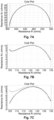
- Example U/V plots for the measurement example shown in Figure 7B are shown in Figures 8A to 8C , respectively.
- Figure 8A shows a U/V plot for the original data
- Figure 8B shows optimum phase correction
- Figure 8C showing too much phase correction.
- the phase correction value can be iteratively determined, until the U/V plot is sufficiently close to a straight line.
- the process typically includes determining a trial phase correction, applying this to the measured impedance values and calculating the impedance curve.
- the impedance curve is used to derive the U/V correlation coefficient, with this process being repeated iteratively for different phase correction values until the correlation coefficient reaches a sufficient value.
- phase correction only affects the high frequency data, and sometimes there may be artefacts at the low frequency part of the spectrum, the optimisation is typically only performed on approximately the upper three quarters of the measurement data (equivalent to frequencies over about 12 kHz).
- the corrected data, ⁇ ', R' and Xc' are used in all analysis with the original
Landscapes
- Health & Medical Sciences (AREA)
- Life Sciences & Earth Sciences (AREA)
- Engineering & Computer Science (AREA)
- Medical Informatics (AREA)
- Surgery (AREA)
- Biophysics (AREA)
- Pathology (AREA)
- Veterinary Medicine (AREA)
- Biomedical Technology (AREA)
- Heart & Thoracic Surgery (AREA)
- Public Health (AREA)
- Molecular Biology (AREA)
- Physics & Mathematics (AREA)
- Animal Behavior & Ethology (AREA)
- General Health & Medical Sciences (AREA)
- Artificial Intelligence (AREA)
- Computer Vision & Pattern Recognition (AREA)
- Physiology (AREA)
- Psychiatry (AREA)
- Signal Processing (AREA)
- Nuclear Medicine, Radiotherapy & Molecular Imaging (AREA)
- Radiology & Medical Imaging (AREA)
- Measurement And Recording Of Electrical Phenomena And Electrical Characteristics Of The Living Body (AREA)
Claims (15)
- Impedanzmesssystem zum Durchführen einer Bioimpedanzmessung an einem biologischen Subjekt, wobei das System Folgendes umfasst:a) einen Signalgenerator, der dazu ausgelegt ist, alternierende Signale bei einer Mehrzahl von unterschiedlichen Frequenzen an zumindest einen Teil des biologischen Subjekts anzulegen;b) einen Sensor, der dazu ausgelegt ist, Antwortsignale von dem biologischen Subjekt zu messen; undc) eine oder mehrere elektronische Verarbeitungsvorrichtungen, die:i) die Bioimpedanzmessung als eine Mehrzahl von Impedanzwerten, die bei der Mehrzahl von unterschiedlichen Frequenzen erhalten werden, unter Verwendung der gemessenen Antwortsignale bestimmen;ii) eine Impedanzkurve unter Verwendung eines Kurvenanpassungsalgorithmus berechnen;iii) eine Abweichung der Impedanzkurve von der Mehrzahl von Impedanzwerten der Bioimpedanzmessung bestimmen; undiv) die Abweichung verwenden, um eine Bewertung der Bioimpedanzmessung durchzuführen, dadurch gekennzeichnet, dass die Bewertung der Bioimpedanzmessung verwendet wird, um die Bioimpedanzmessung zu kategorisieren und einen Indikator abzuleiten, der die Messkategorisierung anzeigt.
- System nach Anspruch 1, wobei die Impedanzmessung als mindestens eines von Folgendem kategorisiert wird:a) mangelhaft;b) zweifelhaft; undc) akzeptabel.
- System nach einem der Ansprüche 1 bis 2, wobei die eine oder mehreren Verarbeitungsvorrichtungen:a) Kurvenkoeffizienten unter Verwendung des Kurvenanpassungsalgorithmus berechnen; undb) die Abweichung unter Verwendung der Kurvenkoeffizienten und der Impedanzwerte bestimmen.
- System nach einem der Ansprüche 1 bis 3, wobei die eine oder mehreren Verarbeitungsvorrichtungen:a) die Abweichung verwenden, um einen geschätzten Fehler in Impedanzparameterwerten zu berechnen, wobei die Impedanzparameterwerte aus der Impedanzkurve abgeleitet werden und die eine oder mehreren Verarbeitungsvorrichtungen einen geschätzten Fehler durch Fortpflanzung der Abweichung auf die Impedanzparameterwerte berechnen; undb) den geschätzten Fehler verwenden, um die Impedanzmessungen zu bewerten.
- System nach einem der Ansprüche 1 bis 4, wobei die eine oder mehreren Verarbeitungsvorrichtungen:a) die Abweichung durch Berechnen einer Kovarianzmatrix bestimmen, die Varianzen und Kovarianzen anzeigt, die mit der Impedanzkurve und den Impedanzwerten assoziiert sind; und,b) die Kovarianzmatrix verwenden, um den Fehler zu schätzen.
- System nach Anspruch 5, wobei mindestens eines von Folgendem zutrifft:a) die Kovarianzmatrix wird basierend auf einem mittleren quadratischen Fehler der Impedanzkurve und der Impedanzwerte erzeugt;b) die eine oder mehreren Verarbeitungsvorrichtungen berechnen die Kovarianzmatrix unter Verwendung der folgenden Gleichung:
 wobei: A eine Matrix von gemessenen Reaktanzwerten X undWiderstandswerten R der Form A = [1 R X] ist
- System nach einem der Ansprüche 1 bis 6, wobei die eine oder mehreren Verarbeitungsvorrichtungen einen geschätzten Fehler mit mindestens einem von Folgendem berechnen:a) unter Verwendung von Teilableitungen erster Ordnung einer Vektorfunktion;b) unter Verwendung einer Jacobi-Transformation; undc) durch Anwenden einer Jacobi-Transformation auf eine Kovarianzmatrix unter Verwendung der folgenden Gleichung:
 wobei: J eine Jacobi-Transformation ist;JT eine inverse Jacobi-Transformation ist;
- System nach einem der Ansprüche 1 bis 7, wobei die eine oder mehreren Verarbeitungsvorrichtungen:a) einen Fehlerwert berechnen, der mit einer Anzahl von Impedanzparameterwerten assoziiert ist, wobei optional:i) die Impedanzparameterwerte eines oder mehrere von Folgendem umfassen:(1) R0, das die theoretische Impedanz bei einer Frequenz von 0 kHz ist;(2) Rinf, das die theoretische Impedanz bei einer unendlichen Frequenz ist; und(3) Ri , das die intrazelluläre Impedanz ist; undii) die eine oder mehreren Verarbeitungsvorrichtungen Fehlerwerte unter Verwendung der folgenden Gleichungen berechnen:(1) für R0 :

 wobei: JR0 eine Jacobi-Transformation für R0 ist;JT R0 eine inverse Jacobi-Transformation für R0 ist; und
 (2) für Rinf
 wobei: JRinf eine Jacobi-Transformation für Rinf ist;JT Rinf eine inverse Jacobi-Transformation für Rinf ist; und
 (3) für Ri
 wobei: JRi eine Jacobi-Transformation für Ri ist;JT Ri eine inverse Jacobi-Transformation für Ri ist; und
 b) jeden Fehlerwert mit mindestens einem jeweiligen Schwellenwert vergleichen; undc) die Bewertung basierend auf Ergebnissen des Vergleichs durchführen.
 - System nach einem der Ansprüche 1 bis 8, wobei die eine oder mehreren Verarbeitungsvorrichtungen die Impedanzmessung basierend auf einer Anzahl negativer Reaktanzwerte bewerten.
- System nach einem der Ansprüche 1 bis 9, wobei die eine oder mehreren Verarbeitungsvorrichtungen die Impedanzmessung als in Folgendem liegend bewerten:a) in einer ersten Kategorie, wenn mindestens eines von Folgendem zutrifft:i) eine Anzahl negativer Reaktanzmessungen überschreitet einen Reaktanzschwellenwert der ersten Kategorie; oderii) mindestens ein Parameterwert weist einen Fehler auf, der größer als ein jeweiliger erster Kategorieschwellenwert ist;b) in einer zweiten Kategorie, wenn mindestens eines von Folgendem zutrifft:i) eine Anzahl negativer Reaktanzmessungen überschreitet einen Reaktanzschwellenwert der zweiten Kategorie;ii) jeder Parameterwert weist einen Fehler auf, der größer als ein jeweiliger zweiter Kategorieschwellenwert ist;c) in einer dritten Kategorie, wenn sie nicht in der ersten oder zweiten Kategorie liegt.
- System nach einem der Ansprüche 1 bis 10, wobei die eine oder mehreren Verarbeitungsvorrichtungen die Messung zumindest teilweise unter Verwendung eines mehrerer Schwellenwerte bewerten, und wobei die Schwellenwerte mindestens eines von Folgendem sind:a) bestimmt basierend auf einer Bewertung vorheriger Impedanzmessungen, die für das Subjekt durchgeführt wurden;b) bestimmt basierend auf einer Bewertung der Impedanz vorheriger Messungen, die für ein oder mehrere Referenzsubjekte durchgeführt wurden; undc) bestimmt durch Anwenden von maschinellem Lernen auf die Bewertung vorheriger Impedanzmessungen, die für ein oder mehrere Referenzsubjekte durchgeführt wurden.
- System nach einem der Ansprüche 1 bis 11, wobei die eine oder mehreren Verarbeitungsvorrichtungen die Messung unter Verwendung mindestens eines Rechenmodells bewerten, das eine Beziehung zwischen unterschiedlichen Abweichungen und einer Messvalidität ausdrückt.
- System nach einem der Ansprüche 1 bis 12, wobei die eine oder mehreren Verarbeitungsvorrichtungen:a) eine Phasenkorrektur auf Impedanzwerte anwenden, die bei einer Frequenz gemessen werden, die höher als eine eingestellte Frequenz ist; undb) die Impedanzkurve unter Verwendung der phasenkorrigierten Impedanzwerte berechnen.
- System nach einem der Ansprüche 1 bis 13, wobei die eine oder mehreren Verarbeitungsvorrichtungen:a) einen Impedanzparameterwert unter Verwendung der Impedanzwerte berechnen;b) den Impedanzparameterwert mit einem definierten Frequenzimpedanzwert vergleichen, wobei der definierte Frequenzimpedanzwert aus einem Impedanzwert bestimmt wird, der aus Impedanzmessungen erhalten wird, die bei einer definierten Messfrequenz durchgeführt werden; undc) ein Ergebnis des Vergleichs verwenden, um eine Bewertung der Impedanzmessungen durchzuführen.
- Verfahren zur Verwendung beim Bewerten einer Bioimpedanzmessung, die an einem biologischen Subjekt durchgeführt wird, wobei das Verfahren, in einer oder mehreren elektronischen Verarbeitungsvorrichtungen, Folgendes umfasst:a) Bestimmen der Bioimpedanzmessung als eine Mehrzahl von Impedanzwerten, die aus Impedanzmessungen erhalten werden, die bei einer Mehrzahl von unterschiedlichen Frequenzen an zumindest einem Teil des biologischen Subjekts durchgeführt werden;b) Berechnen einer Impedanzkurve unter Verwendung eines Kurvenanpassungsalgorithmus;c) Bestimmen einer Abweichung der Impedanzkurve von der Mehrzahl von Impedanzwerten der Bioimpedanzmessung; undd) Verwenden der Abweichung, um eine Bewertung der Bioimpedanzmessung durchzuführen, um die Bioimpedanzmessung zu kategorisieren und einen Indikator abzuleiten, der die Messkategorisierung anzeigt.
Applications Claiming Priority (3)
| Application Number | Priority Date | Filing Date | Title |
|---|---|---|---|
| US201862737721P | 2018-09-27 | 2018-09-27 | |
| US201962842804P | 2019-05-03 | 2019-05-03 | |
| PCT/AU2019/051006 WO2020061619A1 (en) | 2018-09-27 | 2019-09-20 | Evaluating impedance measurements |
Publications (3)
| Publication Number | Publication Date |
|---|---|
| EP3856024A1 EP3856024A1 (de) | 2021-08-04 |
| EP3856024A4 EP3856024A4 (de) | 2022-06-22 |
| EP3856024B1 true EP3856024B1 (de) | 2025-07-02 |
Family
ID=69949213
Family Applications (1)
| Application Number | Title | Priority Date | Filing Date |
|---|---|---|---|
| EP19866489.8A Active EP3856024B1 (de) | 2018-09-27 | 2019-09-20 | Auswertung von impedanzmessungen |
Country Status (6)
| Country | Link |
|---|---|
| US (1) | US20220007956A1 (de) |
| EP (1) | EP3856024B1 (de) |
| JP (1) | JP7410937B2 (de) |
| CN (1) | CN112770669A (de) |
| AU (1) | AU2019348188B2 (de) |
| WO (1) | WO2020061619A1 (de) |
Families Citing this family (11)
| Publication number | Priority date | Publication date | Assignee | Title |
|---|---|---|---|---|
| US20230233146A1 (en) * | 2020-06-12 | 2023-07-27 | Terumo Kabushiki Kaisha | Edema detection |
| US12558470B2 (en) | 2020-12-31 | 2026-02-24 | Corren Medical, Inc. | Guided blood filtration therapy, systems, and methods |
| CN115251879A (zh) * | 2022-06-29 | 2022-11-01 | 芯海科技(深圳)股份有限公司 | 生物阻抗测量方法、装置、设备及存储介质 |
| CN115295139A (zh) * | 2022-08-02 | 2022-11-04 | 北京大学口腔医学院 | 基于生物电阻抗的水肿监测系统 |
| CN116087616A (zh) * | 2022-11-15 | 2023-05-09 | 南京大学 | 一种一次性使用心电电极交流阻抗特性的评价方法 |
| CN115778356A (zh) * | 2022-11-23 | 2023-03-14 | 成都芯海创芯科技有限公司 | 人体阻抗异常测量姿势的识别方法、电子设备及存储介质 |
| CN116027180B (zh) * | 2023-03-30 | 2023-06-23 | 常州海弘电子有限公司 | 一种pcb板高阻抗的性能检测方法及系统 |
| JP2024145708A (ja) * | 2023-03-31 | 2024-10-15 | テルモ株式会社 | 身体組成計測装置、制御方法、および制御プログラム |
| CN117017259A (zh) * | 2023-07-19 | 2023-11-10 | 新绎健康科技有限公司 | 一种定量测定皮肤阻抗的方法 |
| CN117017261B (zh) * | 2023-08-17 | 2025-08-29 | 广州中康先觉健康科技有限责任公司 | 一种电极接触状况自动检测方法 |
| CN120501405B (zh) * | 2025-07-22 | 2025-11-14 | 杭州永川科技有限公司 | 一种电阻抗检测方法、装置、电子装置和存储介质 |
Family Cites Families (23)
| Publication number | Priority date | Publication date | Assignee | Title |
|---|---|---|---|---|
| US5372141A (en) * | 1992-07-01 | 1994-12-13 | Body Composition Analyzers, Inc. | Body composition analyzer |
| US6678552B2 (en) * | 1994-10-24 | 2004-01-13 | Transscan Medical Ltd. | Tissue characterization based on impedance images and on impedance measurements |
| JP3747143B2 (ja) | 2000-03-30 | 2006-02-22 | 株式会社タニタ | 生体電気インピーダンス測定装置 |
| JP3699338B2 (ja) | 2000-06-28 | 2005-09-28 | 株式会社タニタ | 生体電気インピーダンス測定装置 |
| JP2004255120A (ja) * | 2003-02-28 | 2004-09-16 | Tanita Corp | 体組成推定法及び体組成測定装置 |
| JP2005080720A (ja) | 2003-09-05 | 2005-03-31 | Tanita Corp | 生体電気インピーダンス測定装置 |
| JP2008544777A (ja) | 2005-07-01 | 2008-12-11 | インぺディメッド リミテッド | 監視システム |
| US7340294B2 (en) * | 2005-08-11 | 2008-03-04 | The General Electric Company | Impedance measurement apparatus for assessment of biomedical electrode interface quality |
| US9254163B2 (en) * | 2005-12-06 | 2016-02-09 | St. Jude Medical, Atrial Fibrillation Division, Inc. | Assessment of electrode coupling for tissue ablation |
| JP5431147B2 (ja) * | 2006-05-30 | 2014-03-05 | インぺディメッド リミテッド | インピーダンス測定 |
| EP2091425A4 (de) * | 2006-11-30 | 2012-07-25 | Impedimed Ltd | Messgerät |
| AU2008324750B2 (en) | 2007-11-05 | 2014-01-16 | Impedimed Limited | Impedance determination |
| JP5110277B2 (ja) | 2007-11-07 | 2012-12-26 | Skメディカル電子株式会社 | 身体組成推計装置及び身体組成推計方法 |
| US20100268110A1 (en) * | 2009-03-16 | 2010-10-21 | Beltran Nohra E | Systems and methods for characteristic parameter estimation of gastric impedance spectra in humans |
| KR20130098141A (ko) * | 2010-04-26 | 2013-09-04 | 싸이베이스 에이비 | 조직에 대한 전기 임피던스 측정의 품질 평가 방법 및 장치 |
| US8868205B2 (en) * | 2010-12-20 | 2014-10-21 | General Electric Company | System and method for determining physiological parameters based on electrical impedance measurements |
| US9265557B2 (en) * | 2011-01-31 | 2016-02-23 | Medtronic Ablation Frontiers Llc | Multi frequency and multi polarity complex impedance measurements to assess ablation lesions |
| WO2012110042A1 (en) * | 2011-02-17 | 2012-08-23 | Sense A/S | A method of and a system for determining a cardiovascular quantity of a mammal |
| US9861746B2 (en) * | 2012-06-08 | 2018-01-09 | Medtronic Minimed, Inc. | Application of electrochemical impedance spectroscopy in sensor systems, devices, and related methods |
| US20170325711A1 (en) * | 2013-01-29 | 2017-11-16 | Seca Ag | Method and apparatus for testing plausibility of measurement values in body composition analysis |
| US9949663B1 (en) * | 2014-11-13 | 2018-04-24 | Ori Diagnostic Instruments, LLC | Apparatus and method for the analysis of the change of body composition and hydration status and for dynamic indirect individualized measurement of components of the human energy metabolism |
| RU2017140233A (ru) | 2015-05-12 | 2019-06-13 | Навикс Интернэшнл Лимитед | Оценка качества контакта посредством анализа диэлектрических свойств |
| KR101696791B1 (ko) * | 2015-07-31 | 2017-01-17 | 연세대학교 원주산학협력단 | 흉부임피던스를 이용한 폐기능 모니터링 장치 및 방법 |
-
2019
- 2019-09-20 AU AU2019348188A patent/AU2019348188B2/en active Active
- 2019-09-20 WO PCT/AU2019/051006 patent/WO2020061619A1/en not_active Ceased
- 2019-09-20 EP EP19866489.8A patent/EP3856024B1/de active Active
- 2019-09-20 CN CN201980063134.9A patent/CN112770669A/zh active Pending
- 2019-09-20 JP JP2021517435A patent/JP7410937B2/ja active Active
- 2019-09-20 US US17/280,740 patent/US20220007956A1/en active Pending
Also Published As
| Publication number | Publication date |
|---|---|
| EP3856024A4 (de) | 2022-06-22 |
| WO2020061619A1 (en) | 2020-04-02 |
| JP2022511363A (ja) | 2022-01-31 |
| EP3856024A1 (de) | 2021-08-04 |
| US20220007956A1 (en) | 2022-01-13 |
| JP7410937B2 (ja) | 2024-01-10 |
| CN112770669A (zh) | 2021-05-07 |
| AU2019348188A1 (en) | 2021-04-22 |
| AU2019348188B2 (en) | 2024-10-17 |
Similar Documents
| Publication | Publication Date | Title |
|---|---|---|
| EP3856024B1 (de) | Auswertung von impedanzmessungen | |
| US9615767B2 (en) | Fluid level indicator determination | |
| JP5970476B2 (ja) | 組織量指標の決定 | |
| JP6813563B2 (ja) | 流体レベルの決定 | |
| JP2023171493A (ja) | 指標の決定 | |
| AU2011274290B2 (en) | Tissue indicator determination | |
| AU2014202075B2 (en) | Fluid level indicator determination |
Legal Events
| Date | Code | Title | Description |
|---|---|---|---|
| STAA | Information on the status of an ep patent application or granted ep patent |
Free format text: STATUS: THE INTERNATIONAL PUBLICATION HAS BEEN MADE |
|
| PUAI | Public reference made under article 153(3) epc to a published international application that has entered the european phase |
Free format text: ORIGINAL CODE: 0009012 |
|
| STAA | Information on the status of an ep patent application or granted ep patent |
Free format text: STATUS: REQUEST FOR EXAMINATION WAS MADE |
|
| 17P | Request for examination filed |
Effective date: 20210216 |
|
| AK | Designated contracting states |
Kind code of ref document: A1 Designated state(s): AL AT BE BG CH CY CZ DE DK EE ES FI FR GB GR HR HU IE IS IT LI LT LU LV MC MK MT NL NO PL PT RO RS SE SI SK SM TR |
|
| DAV | Request for validation of the european patent (deleted) | ||
| DAX | Request for extension of the european patent (deleted) | ||
| A4 | Supplementary search report drawn up and despatched |
Effective date: 20220520 |
|
| RIC1 | Information provided on ipc code assigned before grant |
Ipc: A61B 5/0537 20210101ALI20220516BHEP Ipc: A61B 5/053 20210101AFI20220516BHEP |
|
| P01 | Opt-out of the competence of the unified patent court (upc) registered |
Effective date: 20230510 |
|
| STAA | Information on the status of an ep patent application or granted ep patent |
Free format text: STATUS: EXAMINATION IS IN PROGRESS |
|
| 17Q | First examination report despatched |
Effective date: 20241001 |
|
| GRAP | Despatch of communication of intention to grant a patent |
Free format text: ORIGINAL CODE: EPIDOSNIGR1 |
|
| STAA | Information on the status of an ep patent application or granted ep patent |
Free format text: STATUS: GRANT OF PATENT IS INTENDED |
|
| INTG | Intention to grant announced |
Effective date: 20250218 |
|
| GRAS | Grant fee paid |
Free format text: ORIGINAL CODE: EPIDOSNIGR3 |
|
| GRAA | (expected) grant |
Free format text: ORIGINAL CODE: 0009210 |
|
| STAA | Information on the status of an ep patent application or granted ep patent |
Free format text: STATUS: THE PATENT HAS BEEN GRANTED |
|
| AK | Designated contracting states |
Kind code of ref document: B1 Designated state(s): AL AT BE BG CH CY CZ DE DK EE ES FI FR GB GR HR HU IE IS IT LI LT LU LV MC MK MT NL NO PL PT RO RS SE SI SK SM TR |
|
| REG | Reference to a national code |
Ref country code: GB Ref legal event code: FG4D |
|
| REG | Reference to a national code |
Ref country code: CH Ref legal event code: EP |
|
| REG | Reference to a national code |
Ref country code: DE Ref legal event code: R096 Ref document number: 602019072091 Country of ref document: DE |
|
| REG | Reference to a national code |
Ref country code: IE Ref legal event code: FG4D |
|
| PGFP | Annual fee paid to national office [announced via postgrant information from national office to epo] |
Ref country code: DE Payment date: 20250919 Year of fee payment: 7 |
|
| PGFP | Annual fee paid to national office [announced via postgrant information from national office to epo] |
Ref country code: GB Payment date: 20250919 Year of fee payment: 7 |
|
| PGFP | Annual fee paid to national office [announced via postgrant information from national office to epo] |
Ref country code: FR Payment date: 20250922 Year of fee payment: 7 |
|
| REG | Reference to a national code |
Ref country code: NL Ref legal event code: MP Effective date: 20250702 |
|
| PG25 | Lapsed in a contracting state [announced via postgrant information from national office to epo] |
Ref country code: PT Free format text: LAPSE BECAUSE OF FAILURE TO SUBMIT A TRANSLATION OF THE DESCRIPTION OR TO PAY THE FEE WITHIN THE PRESCRIBED TIME-LIMIT Effective date: 20251103 |
|
| PG25 | Lapsed in a contracting state [announced via postgrant information from national office to epo] |
Ref country code: NL Free format text: LAPSE BECAUSE OF FAILURE TO SUBMIT A TRANSLATION OF THE DESCRIPTION OR TO PAY THE FEE WITHIN THE PRESCRIBED TIME-LIMIT Effective date: 20250702 |
|
| REG | Reference to a national code |
Ref country code: AT Ref legal event code: MK05 Ref document number: 1808293 Country of ref document: AT Kind code of ref document: T Effective date: 20250702 |
|
| PG25 | Lapsed in a contracting state [announced via postgrant information from national office to epo] |
Ref country code: IS Free format text: LAPSE BECAUSE OF FAILURE TO SUBMIT A TRANSLATION OF THE DESCRIPTION OR TO PAY THE FEE WITHIN THE PRESCRIBED TIME-LIMIT Effective date: 20251102 |
|
| PG25 | Lapsed in a contracting state [announced via postgrant information from national office to epo] |
Ref country code: NO Free format text: LAPSE BECAUSE OF FAILURE TO SUBMIT A TRANSLATION OF THE DESCRIPTION OR TO PAY THE FEE WITHIN THE PRESCRIBED TIME-LIMIT Effective date: 20251002 |
|
| REG | Reference to a national code |
Ref country code: LT Ref legal event code: MG9D |
|
| PG25 | Lapsed in a contracting state [announced via postgrant information from national office to epo] |
Ref country code: AT Free format text: LAPSE BECAUSE OF FAILURE TO SUBMIT A TRANSLATION OF THE DESCRIPTION OR TO PAY THE FEE WITHIN THE PRESCRIBED TIME-LIMIT Effective date: 20250702 |
|
| PG25 | Lapsed in a contracting state [announced via postgrant information from national office to epo] |
Ref country code: FI Free format text: LAPSE BECAUSE OF FAILURE TO SUBMIT A TRANSLATION OF THE DESCRIPTION OR TO PAY THE FEE WITHIN THE PRESCRIBED TIME-LIMIT Effective date: 20250702 |
|
| PG25 | Lapsed in a contracting state [announced via postgrant information from national office to epo] |
Ref country code: HR Free format text: LAPSE BECAUSE OF FAILURE TO SUBMIT A TRANSLATION OF THE DESCRIPTION OR TO PAY THE FEE WITHIN THE PRESCRIBED TIME-LIMIT Effective date: 20250702 |
|
| PG25 | Lapsed in a contracting state [announced via postgrant information from national office to epo] |
Ref country code: GR Free format text: LAPSE BECAUSE OF FAILURE TO SUBMIT A TRANSLATION OF THE DESCRIPTION OR TO PAY THE FEE WITHIN THE PRESCRIBED TIME-LIMIT Effective date: 20251003 |
|
| PG25 | Lapsed in a contracting state [announced via postgrant information from national office to epo] |
Ref country code: CZ Free format text: LAPSE BECAUSE OF FAILURE TO SUBMIT A TRANSLATION OF THE DESCRIPTION OR TO PAY THE FEE WITHIN THE PRESCRIBED TIME-LIMIT Effective date: 20250702 Ref country code: SE Free format text: LAPSE BECAUSE OF FAILURE TO SUBMIT A TRANSLATION OF THE DESCRIPTION OR TO PAY THE FEE WITHIN THE PRESCRIBED TIME-LIMIT Effective date: 20250702 |
|
| PG25 | Lapsed in a contracting state [announced via postgrant information from national office to epo] |
Ref country code: LV Free format text: LAPSE BECAUSE OF FAILURE TO SUBMIT A TRANSLATION OF THE DESCRIPTION OR TO PAY THE FEE WITHIN THE PRESCRIBED TIME-LIMIT Effective date: 20250702 |
|
| PG25 | Lapsed in a contracting state [announced via postgrant information from national office to epo] |
Ref country code: BG Free format text: LAPSE BECAUSE OF FAILURE TO SUBMIT A TRANSLATION OF THE DESCRIPTION OR TO PAY THE FEE WITHIN THE PRESCRIBED TIME-LIMIT Effective date: 20250702 Ref country code: PL Free format text: LAPSE BECAUSE OF FAILURE TO SUBMIT A TRANSLATION OF THE DESCRIPTION OR TO PAY THE FEE WITHIN THE PRESCRIBED TIME-LIMIT Effective date: 20250702 |
|
| PG25 | Lapsed in a contracting state [announced via postgrant information from national office to epo] |
Ref country code: RS Free format text: LAPSE BECAUSE OF FAILURE TO SUBMIT A TRANSLATION OF THE DESCRIPTION OR TO PAY THE FEE WITHIN THE PRESCRIBED TIME-LIMIT Effective date: 20251002 |
|
| PG25 | Lapsed in a contracting state [announced via postgrant information from national office to epo] |
Ref country code: ES Free format text: LAPSE BECAUSE OF FAILURE TO SUBMIT A TRANSLATION OF THE DESCRIPTION OR TO PAY THE FEE WITHIN THE PRESCRIBED TIME-LIMIT Effective date: 20250702 |
|
| PG25 | Lapsed in a contracting state [announced via postgrant information from national office to epo] |
Ref country code: RO Free format text: LAPSE BECAUSE OF FAILURE TO SUBMIT A TRANSLATION OF THE DESCRIPTION OR TO PAY THE FEE WITHIN THE PRESCRIBED TIME-LIMIT Effective date: 20250702 |