EP3855246A1 - Camera with phased metalens - Google Patents
Camera with phased metalens Download PDFInfo
- Publication number
- EP3855246A1 EP3855246A1 EP20207221.1A EP20207221A EP3855246A1 EP 3855246 A1 EP3855246 A1 EP 3855246A1 EP 20207221 A EP20207221 A EP 20207221A EP 3855246 A1 EP3855246 A1 EP 3855246A1
- Authority
- EP
- European Patent Office
- Prior art keywords
- camera
- metalens
- phased
- light
- center
- Prior art date
- Legal status (The legal status is an assumption and is not a legal conclusion. Google has not performed a legal analysis and makes no representation as to the accuracy of the status listed.)
- Granted
Links
Images



Classifications
-
- G—PHYSICS
- G03—PHOTOGRAPHY; CINEMATOGRAPHY; ANALOGOUS TECHNIQUES USING WAVES OTHER THAN OPTICAL WAVES; ELECTROGRAPHY; HOLOGRAPHY
- G03B—APPARATUS OR ARRANGEMENTS FOR TAKING PHOTOGRAPHS OR FOR PROJECTING OR VIEWING THEM; APPARATUS OR ARRANGEMENTS EMPLOYING ANALOGOUS TECHNIQUES USING WAVES OTHER THAN OPTICAL WAVES; ACCESSORIES THEREFOR
- G03B3/00—Focusing arrangements of general interest for cameras, projectors or printers
-
- G—PHYSICS
- G03—PHOTOGRAPHY; CINEMATOGRAPHY; ANALOGOUS TECHNIQUES USING WAVES OTHER THAN OPTICAL WAVES; ELECTROGRAPHY; HOLOGRAPHY
- G03B—APPARATUS OR ARRANGEMENTS FOR TAKING PHOTOGRAPHS OR FOR PROJECTING OR VIEWING THEM; APPARATUS OR ARRANGEMENTS EMPLOYING ANALOGOUS TECHNIQUES USING WAVES OTHER THAN OPTICAL WAVES; ACCESSORIES THEREFOR
- G03B13/00—Viewfinders; Focusing aids for cameras; Means for focusing for cameras; Autofocus systems for cameras
- G03B13/18—Focusing aids
- G03B13/24—Focusing screens
-
- H—ELECTRICITY
- H04—ELECTRIC COMMUNICATION TECHNIQUE
- H04N—PICTORIAL COMMUNICATION, e.g. TELEVISION
- H04N23/00—Cameras or camera modules comprising electronic image sensors; Control thereof
- H04N23/58—Means for changing the camera field of view without moving the camera body, e.g. nutating or panning of optics or image sensors
-
- G—PHYSICS
- G02—OPTICS
- G02B—OPTICAL ELEMENTS, SYSTEMS OR APPARATUS
- G02B1/00—Optical elements characterised by the material of which they are made; Optical coatings for optical elements
- G02B1/002—Optical elements characterised by the material of which they are made; Optical coatings for optical elements made of materials engineered to provide properties not available in nature, e.g. metamaterials
-
- G—PHYSICS
- G02—OPTICS
- G02B—OPTICAL ELEMENTS, SYSTEMS OR APPARATUS
- G02B26/00—Optical devices or arrangements for the control of light using movable or deformable optical elements
- G02B26/06—Optical devices or arrangements for the control of light using movable or deformable optical elements for controlling the phase of light
-
- H—ELECTRICITY
- H04—ELECTRIC COMMUNICATION TECHNIQUE
- H04N—PICTORIAL COMMUNICATION, e.g. TELEVISION
- H04N23/00—Cameras or camera modules comprising electronic image sensors; Control thereof
- H04N23/60—Control of cameras or camera modules
- H04N23/67—Focus control based on electronic image sensor signals
- H04N23/672—Focus control based on electronic image sensor signals based on the phase difference signals
Definitions
- This disclosure generally relates to a camera.
- Fixed focus cameras are typically aligned and focused at room temperature. These cameras may experience defocus, also known as a change in back focal length, over operating temperatures associated with various automotive applications due to thermal expansion and contraction of the camera.
- An example of a camera includes a phased metalens positioned between an objective lens and an imager of the camera.
- the phased metalens is configured to adjust a focus plane of an image in a field of view of the camera in response to changes in an operating temperature of the camera.
- the phased metalens is positioned within 1mm of an imager focal plane.
- the phased metalens adjusts the focus plane for multiple frequencies or wavelengths of the light.
- the wavelengths range from 400 nanometers (400nm) to 1600nm.
- the phased metalens adjusts the focus plane over a temperature range of about 145 degrees Celsius.
- the phased metalens adjusts the focus plane over changes in a focal length of about 16 microns (16 ⁇ m).
- the phased metalens comprises a plurality of sub-wavelength structures positioned at predetermined coordinates across the phased metalens.
- the plurality of sub-wavelength structures range from two times to eight times smaller than a wavelength of the light transmitted through the phased metalens.
- the plurality of sub-wavelength structures are grouped into a plurality of arrangements having unique phase profiles; the unique phase profiles configured to adjust a phase of the light transmitted through the plurality of arrangements.
- the unique phase profiles are based on the arrangement's respective radial distance from a center of the phased metalens.
- the unique phase profiles are based on an operating temperature of the camera.
- the plurality of arrangements define a plurality of resolution units.
- the plurality of resolution units located at a same radius from a center of the phased metalens have identical phase profiles.
- the plurality of resolution units located at a different radius from a center of the phased metalens have different phase profiles.
- a size of one resolution unit is equal a size of four image pixels.
- each image pixel includes about 30 to 36 sub-wavelength structures.
- each resolution unit includes about 120 to 144 sub-wavelength structures.
- the unique phase profiles increase an amount of phase adjustment for a given wavelength of light.
- the unique phase profiles increase an amount of phase adjustment for decreasing wavelengths of the light.
- the unique phase profiles increase an amount of phase adjustment for a given temperature.
- the unique phase profiles increase an amount of phase adjustment for increasing temperatures.
- all light wave-fronts exiting the phased metalens arrive at the imager at a same time.
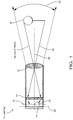
- Fig. 1 illustrates a cross sectional view of a camera 10 that includes an objective lens 12 and an imager 14. While the examples illustrated herein disclose the camera 10, it will be appreciated that the disclosure also applies to other devices or sensors that sense electromagnetic radiation, such as light detection and ranging (LiDAR) sensors. Multiple camera lenses (not shown) of varying geometries may be used in the camera 10, depending on the application requirements.
- the imager 14 may be in electrical communication with a controller circuit (not shown) to process an image 16 of an object 18 in a field of view 20 of the camera 10. In the example illustrated in Fig. 1 , a focal length of the camera 10 is fixed.
- the camera 10 does not include a mechanical or electrical focus adjustment device to refocus the image 16 when a focus plane 22 of the camera 10 moves away from the imager 14 (i.e., a defocus).
- thermal expansion and contraction of the camera 10 due to an operating temperature variation, may cause the camera 10 to defocus.
- the focus plane 22 may move in a positive direction (i.e., toward the objective lens 12) or a negative direction (i.e., toward the imager 14) along an optical axis 28 of the camera 10, due to thermal expansion or thermal contraction of the camera 10.
- a typical camera used for advanced driver assistance systems may be required to operate over a temperature range of -40°C to +105°C.
- ADAS cameras are typically focused at 25°C.
- this temperature range may result in a change in the focal length of the camera 10 by as much as 16 microns (16 ⁇ m).
- ADAS cameras, that have fixed focus lenses with relatively large apertures and relatively low f-stops have a reduced depth of focus compared to more expensive adjustable focus cameras.
- the thermal expansion of ADAS cameras over the 145°C temperature range will cause a significant and measurable (e.g., 25% to 50%) degradation in an image quality, which may negatively affect the ADAS systems.
- a change in back focal length of 15 ⁇ m - 20 ⁇ m would require the same movement by the complete lens system, or could be accomplished by, a) introduction of a lens element index of refractive change (e.g., 6% - 9% or representing a delta change of 0.010 - 0.014), and/or b) lens element material thickness change (e.g., 20 ⁇ m - 30 ⁇ m), and/or c) curvature change (e.g., 50 mm radius of curvature), and/or d) smaller contributions by combinations of the above.
- a lens element index of refractive change e.g., 6% - 9% or representing a delta change of 0.010 - 0.014
- lens element material thickness change e.g., 20 ⁇ m - 30 ⁇ m
- curvature change e.g., 50 mm radius of curvature
- phased metal ens 24 is positioned between the objective lens 12 and the imager 14 of the camera 10, as illustrated in Fig. 1 .
- the phased metalens 24 is configured to adjust the focus plane 22 of the image 16 in the field of view 20 of the camera 10 in response to changes in the operating temperature of the camera 10.
- the phased metalens 24 accomplishes this by shifting a phase of the incoming light rays via sub-wavelength structures 25, as will be described in more detail below.
- These sub-wavelength structures 25 may be deposited on a relatively thin, generally planar, substrate of optically transparent material (e.g., optical glass), and may be formed of metamaterials with structural features that are capable of manipulating the light waves.
- the metamaterials are fabricated using known lithographic processes from compounds such as titanium dioxide, silicon nitride, boron nitride, molybdenum disulfide, or combinations thereof. The metamaterials may be selected based on the wavelengths of the electromagnetic radiation being sensed.
- titanium dioxide may be selected for light in the visible and near infrared spectrum.
- silicon nitride may be selected for light in the visible spectrum.
- boron nitride may be selected for electromagnetic radiation at wavelengths below the visible and near infrared spectrum (e.g., ultraviolet light).
- molybdenum disulfide may be selected for electromagnetic radiation at wavelengths in the near infrared spectrum.
- the sub-wavelength structures 25 are fabricated on an exit side of the substrate (i.e., the side facing the imager 14).
- a cross section of the sub-wavelength structures 25 normal to the incident light rays are rectangular.
- the cross section of the sub-wavelength structures 25 normal to the incident light rays are circular.
- the phased metalens 24 is configured to shift the phase of the incoming light rays such that all light wave-fronts exiting the phased metalens 24 arrive at the imager 14 at a same time, resulting in good focus for all temperature conditions. That is, the phased metalens 24 delays the light wave-fronts by differing amounts, depending on the position of the sub-wavelength structures 25 on the phased metalens 24, such that all the light wave-fronts reaching the imager 14 are in-phase.
- the phased metalens 24 accomplishes this by achieving near diffraction limited focusing over the incoming light wavelengths using precisely defined nanoscale sub-wavelength resolution structures.
- the phased metalens 24 includes the sub-wavelength structures 25 arranged in unique phase profiles for the multiple focal lengths within the resolution unit 30 that result from the temperature changes of the camera 10. That is, the phased metalens 24 includes multiple unique phase profiles designed for multiple offsets of the focal length, so that as the focal length is offset by the temperature change, the light rays exiting the phased metalens 24 will remain in phase.
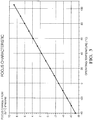
- Fig. 3 illustrates an example of a focus characteristic of the phased metalens 24 of Fig. 1 .
- the phased metalens 24 is configured to adjust the focus plane 22 over the temperature range of about 145°C and over the associated changes in the focal length of about 16 ⁇ m.
- the phased metalens 24 adjusts the focus plane 22 for multiple frequencies or wavelengths of the light.
- the wavelengths range from about 400nm to about 1600nm (i.e., visible light to near infrared light).
- the wavelengths range from about 400nm to about 700nm (i.e., visible light only).
- the wavelengths range from about 700nm to about 1600nm (i.e., near infrared light only).
- phased metalens 24 is placed in close proximity to the imager 14.
- the phased metalens 24 is positioned within 1mm of an imager focal plane 26 (i.e., the imaging surface of the imager 14).
- a thickness of the metalens 24 is less than 1mm, and preferably less than 25 ⁇ m. This relatively thin structure enables the metalens 24 to be positioned in the typically narrow space between the fixed focus objective lens 12 and the imager focal plane 26. This positioning enables a greater flexibility allowing for the compensation of the thermal driven defocus while otherwise being independent of the existing fixed lens system.
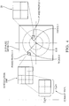
- Fig. 4 illustrates the phased metalens 24 viewed along an optical axis 28 of the camera 10.
- the phased metalens 24 comprises a plurality of sub-wavelength structures 25 (not shown) positioned at predetermined coordinates across the phased metalens 24.
- the plurality of sub-wavelength structures 25 range from two times to eight times smaller than the wavelength of the light transmitted through the phased metalens 24.
- the sub-wavelength structures 25 that shift blue light (having wavelengths that range from 450nm - 485nm) would have cross sectional dimensions normal to the incident light rays that range from 0.050 ⁇ m to 0.150 ⁇ m. It will be recognized that light with longer wavelengths will require larger sub-wavelength structures 25 to cause the phase shift, and that light with shorter wavelengths will require smaller sub-wavelength structures 25 to cause the phase shift.
- the plurality of sub-wavelength structures 25 are grouped into a plurality of arrangements having unique phase profiles that define a plurality resolution units 30 (RUs 30). That is, the plurality of sub-wavelength structures 25 are arranged into RUs 30 that have unique phase profiles that delay the light transmitted through the RUs 30 by differing amounts of time. These unique phase profiles are configured to adjust the phase of the light transmitted through the plurality of RUs 30 based on the operating temperature of the camera 10, and also based on the RU's 30 respective radial distance from a center of the phased metalens 24. Fig.
- FIG. 4 illustrates an example of two separate RUs 30 isolated from the plurality of RUs 30, having different phase profiles as denoted by "PHASE PROFILE 1" within the RU 30 positioned at "RADIUS 1", and by "PHASE PROFILE 2" within the RU 30 positioned at "RADIUS 2".
- the plurality RUs 30 located at a same radius (e.g. RADIUS 1) from a center of the phased metalens 24 have identical phase profiles
- the plurality RUs 30 located at a different radius e.g. RADIUS 2 from the center of the phased metalens 24 have different phase profiles.
- a size of one RU 30 is equal the size of four image pixels 32 of the imager 14.
- the maximum useful image resolution is limited to the Nyquist frequency, i.e., the resolution in pixel size scaled to the camera 10 imager focal plane 26 pixel size. In this example, this is equivalent to the size of four image pixels 32.
- the limiting resolution is an area of 4 ⁇ m x 4 ⁇ m. Within this area, image information is sub-resolved or is not able to be reproduced or imaged, as such the area of 4 ⁇ m x 4 ⁇ m is the limiting dimension of the RU 30.
- Table 1 below illustrates an example of a scale of various characteristics of a 3mm x 3mm phased metalens 24.
- 3mm x 3mm PHASED METALENS FEATURE SIZE RESOLUTION UNIT 16 ⁇ m 2 (4 ⁇ m x 4 ⁇ m)
- IMAGE PIXEL AREA 4 ⁇ m 2 (2 ⁇ m x 2 ⁇ m)
- SUB-WAVELENGTH STRUCTURES WIDTH 0.040 ⁇ m - 0.100 ⁇ m LENGTH 0.150 ⁇ m - 0.400 ⁇ m HEIGHT 0.400 ⁇ m - 0.600 ⁇ m ROTATION 0 - 2 ⁇ RADIANS AREA 0.040 ⁇ m 2 - 0.200 ⁇ m 2 NUMBER OF SUB-WAVELENGTH STRUCTURES WITHIN AN IMAGE PIXEL: 30-36 NUMBER OF SUB-WAVELENGTH STRUCTURES WITHIN A RESOLUTION UNIT: 120 - 144 NUMBER OF RUs: 562,500 NUMBER OF SUB-WAVEL
- each RU 30 includes about 120 to 144 sub-wavelength structures 25.
- a focus characteristic encompassing a range of 11-12 discrete wavelengths with 11-12 discrete temperature offsets may be included within a single RU 30.
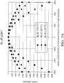
- Figs. 5A-5C are plots of radial distances of the sub-wavelength structures 25 from the center of the phased metalens 24 versus a phase adjustment of the light.
- three colors (i.e. wavelengths) of visible light blue, green, and red
- operating temperatures 40°C, 25°C, and +105°C
- the unique phase profiles increase an amount of phase adjustment for a given wavelength of light.
- the center of the phased metalens 24 is indicated at (0, 0) where the phase adjustment for the three temperatures are nearly zero.
- the phase adjustment increases for the three temperatures indicated.
- the unique phase profiles increase an amount of phase adjustment for decreasing wavelengths of the light. Comparing Fig. 5A , with Fig. 5B , and with Fig. 5C , the phase adjustment for the blue light in Fig. 5A is greater than that for the green light of Fig. 5B , which is in turn greater than that for the red light of Fig. 5C . It will be understood that the wavelength of light increases from blue light to green light to red light.
- the unique phase profiles increase an amount of phase adjustment for a given operating temperature of the camera 10.
- the plots of constant temperature show increasing phase adjustment as the radial distance of the sub-wavelength structures 25 increases from the center of the phased metalens 24.
- the following are some examples related to a camera with phased metalens.
- first contact could be termed a second contact
- second contact could be termed a first contact
- the first contact and the second contact are both contacts, but they are not the same contact.
- the terminology used in the description of the various described embodiments herein is for the purpose of describing particular embodiments only and is not intended to be limiting. As used in the description of the various described embodiments and the appended claims, the singular forms "a”, “an” and “the” are intended to include the plural forms as well, unless the context clearly indicates otherwise. It will also be understood that the term “and/or” as used herein refers to and encompasses any and all possible combinations of one or more of the associated listed items.
- the phrase “if it is determined” or “if [a stated condition or event] is detected” is, optionally, construed to mean “upon determining” or “in response to determining” or “upon detecting [the stated condition or event]” or “in response to detecting [the stated condition or event],” depending on the context.
Landscapes
- Physics & Mathematics (AREA)
- General Physics & Mathematics (AREA)
- Engineering & Computer Science (AREA)
- Multimedia (AREA)
- Signal Processing (AREA)
- Optics & Photonics (AREA)
- Radiation Pyrometers (AREA)
- Solid State Image Pick-Up Elements (AREA)
- Length Measuring Devices By Optical Means (AREA)
Abstract
Description
- This disclosure generally relates to a camera.
- Fixed focus cameras are typically aligned and focused at room temperature. These cameras may experience defocus, also known as a change in back focal length, over operating temperatures associated with various automotive applications due to thermal expansion and contraction of the camera.
- An example of a camera includes a phased metalens positioned between an objective lens and an imager of the camera. The phased metalens is configured to adjust a focus plane of an image in a field of view of the camera in response to changes in an operating temperature of the camera.
- In an example having one or more features of the camera of the previous paragraph, the phased metalens is positioned within 1mm of an imager focal plane.
- In an example having one or more features of the camera of any of the previous paragraphs, the phased metalens adjusts the focus plane for multiple frequencies or wavelengths of the light.
- In an example having one or more features of the camera of any of the previous paragraphs, the wavelengths range from 400 nanometers (400nm) to 1600nm.
- In an example having one or more features of the camera of any of the previous paragraphs, the phased metalens adjusts the focus plane over a temperature range of about 145 degrees Celsius.
- In an example having one or more features of the camera of any of the previous paragraphs, the phased metalens adjusts the focus plane over changes in a focal length of about 16 microns (16µm).
- In an example having one or more features of the camera of any of the previous paragraphs, the phased metalens comprises a plurality of sub-wavelength structures positioned at predetermined coordinates across the phased metalens.
- In an example having one or more features of the camera of any of the previous paragraphs, the plurality of sub-wavelength structures range from two times to eight times smaller than a wavelength of the light transmitted through the phased metalens.
- In an example having one or more features of the camera of any of the previous paragraphs, the plurality of sub-wavelength structures are grouped into a plurality of arrangements having unique phase profiles; the unique phase profiles configured to adjust a phase of the light transmitted through the plurality of arrangements.
- In an example having one or more features of the camera of any of the previous paragraphs, the unique phase profiles are based on the arrangement's respective radial distance from a center of the phased metalens.
- In an example having one or more features of the camera of any of the previous paragraphs, the unique phase profiles are based on an operating temperature of the camera.
- In an example having one or more features of the camera of any of the previous paragraphs, the plurality of arrangements define a plurality of resolution units.
- In an example having one or more features of the camera of any of the previous paragraphs, the plurality of resolution units located at a same radius from a center of the phased metalens have identical phase profiles.
- In an example having one or more features of the camera of any of the previous paragraphs, the plurality of resolution units located at a different radius from a center of the phased metalens have different phase profiles.
- In an example having one or more features of the camera of any of the previous paragraphs, a size of one resolution unit is equal a size of four image pixels.
- In an example having one or more features of the camera of any of the previous paragraphs, each image pixel includes about 30 to 36 sub-wavelength structures.
- In an example having one or more features of the camera of any of the previous paragraphs, each resolution unit includes about 120 to 144 sub-wavelength structures.
- In an example having one or more features of the camera of any of the previous paragraphs, as the respective radial distance of the plurality of resolution units increases from a center of the phased metalens, the unique phase profiles increase an amount of phase adjustment for a given wavelength of light.
- In an example having one or more features of the camera of any of the previous paragraphs, as a radial distance of the plurality of resolution units increases from a center of the phased metalens, the unique phase profiles increase an amount of phase adjustment for decreasing wavelengths of the light.
- In an example having one or more features of the camera of any of the previous paragraphs, as a radial distance of the plurality of resolution units increases from a center of the phased metalens, the unique phase profiles increase an amount of phase adjustment for a given temperature.
- In an example having one or more features of the camera of any of the previous paragraphs, as a radial distance of the plurality of resolution units increases from a center of the phased metalens, the unique phase profiles increase an amount of phase adjustment for increasing temperatures.
- In an example having one or more features of the camera of any of the previous paragraphs, all light wave-fronts exiting the phased metalens arrive at the imager at a same time.
- The present invention will now be described, by way of example with reference to the accompanying drawings, in which:
-
Fig. 1 is an illustration of a cross sectional view of a camera, in accordance with one example; -
Fig. 2 illustrates an example of a focus characteristic of aphased metalens 24; -
Fig. 3 is an illustration of the phased metalens viewed along an optical axis of the camera ofFig. 1 , in accordance with one example; -
Figs. 4A is a plot of phase adjustment for blue light, in accordance with one example; -
Figs. 4B is a plot of phase adjustment for green light, in accordance with one example; and -
Figs. 4C is a plot of phase adjustment for red light, in accordance with one example; - Reference will now be made in detail to embodiments, examples of which are illustrated in the accompanying drawings. In the following detailed description, numerous specific details are set forth in order to provide a thorough understanding of the various described embodiments. However, it will be apparent to one of ordinary skill in the art that the various described embodiments may be practiced without these specific details. In other instances, well-known methods, procedures, components, circuits, and networks have not been described in detail so as not to unnecessarily obscure aspects of the embodiments.
-
Fig. 1 illustrates a cross sectional view of acamera 10 that includes anobjective lens 12 and animager 14. While the examples illustrated herein disclose thecamera 10, it will be appreciated that the disclosure also applies to other devices or sensors that sense electromagnetic radiation, such as light detection and ranging (LiDAR) sensors. Multiple camera lenses (not shown) of varying geometries may be used in thecamera 10, depending on the application requirements. Theimager 14 may be in electrical communication with a controller circuit (not shown) to process animage 16 of anobject 18 in a field ofview 20 of thecamera 10. In the example illustrated inFig. 1 , a focal length of thecamera 10 is fixed. That is, thecamera 10 does not include a mechanical or electrical focus adjustment device to refocus theimage 16 when afocus plane 22 of thecamera 10 moves away from the imager 14 (i.e., a defocus). In an example, thermal expansion and contraction of thecamera 10, due to an operating temperature variation, may cause thecamera 10 to defocus. It will be understood that thefocus plane 22 may move in a positive direction (i.e., toward the objective lens 12) or a negative direction (i.e., toward the imager 14) along anoptical axis 28 of thecamera 10, due to thermal expansion or thermal contraction of thecamera 10. - A typical camera used for advanced driver assistance systems (ADAS) may be required to operate over a temperature range of -40°C to +105°C. ADAS cameras are typically focused at 25°C. Depending on the materials used in the camera body (not specifically shown), spacers, and lenses, this temperature range may result in a change in the focal length of the
camera 10 by as much as 16 microns (16µm). ADAS cameras, that have fixed focus lenses with relatively large apertures and relatively low f-stops, have a reduced depth of focus compared to more expensive adjustable focus cameras. As a result, the thermal expansion of ADAS cameras over the 145°C temperature range will cause a significant and measurable (e.g., 25% to 50%) degradation in an image quality, which may negatively affect the ADAS systems. Autonomous vehicle camera requirements are continuing to drive towardsmaller camera imager 14 pixel sizes (e.g., 2 µm), higher density focal planes (e.g., 8 Megapixel arrays), and higher spatial frequency contrast image quality requirements (e.g., greater than 75 line pairs/mm). Consequently, the image degradation over temperature for the larger format cameras will be proportionately higher and reduce object detection performance. - For a traditional fixed focus lens system, a change in back focal length of 15µm - 20µm would require the same movement by the complete lens system, or could be accomplished by, a) introduction of a lens element index of refractive change (e.g., 6% - 9% or representing a delta change of 0.010 - 0.014), and/or b) lens element material thickness change (e.g., 20µm - 30µm), and/or c) curvature change (e.g., 50 mm radius of curvature), and/or d) smaller contributions by combinations of the above.
- To address the defocus issue of the
fixed focus camera 10, aphased metal ens 24 is positioned between theobjective lens 12 and theimager 14 of thecamera 10, as illustrated inFig. 1 . Thephased metalens 24 is configured to adjust thefocus plane 22 of theimage 16 in the field ofview 20 of thecamera 10 in response to changes in the operating temperature of thecamera 10. Thephased metalens 24 accomplishes this by shifting a phase of the incoming light rays viasub-wavelength structures 25, as will be described in more detail below. These sub-wavelength structures 25 (also referred to as nanostructures) may be deposited on a relatively thin, generally planar, substrate of optically transparent material (e.g., optical glass), and may be formed of metamaterials with structural features that are capable of manipulating the light waves. In an example, the metamaterials are fabricated using known lithographic processes from compounds such as titanium dioxide, silicon nitride, boron nitride, molybdenum disulfide, or combinations thereof. The metamaterials may be selected based on the wavelengths of the electromagnetic radiation being sensed. In an example, titanium dioxide may be selected for light in the visible and near infrared spectrum. In an example, silicon nitride may be selected for light in the visible spectrum. In an example, boron nitride may be selected for electromagnetic radiation at wavelengths below the visible and near infrared spectrum (e.g., ultraviolet light). In an example, molybdenum disulfide may be selected for electromagnetic radiation at wavelengths in the near infrared spectrum. -
Fig. 2 illustrates an example where the wave fronts of the light rays exiting from different regions of the phasedmetalens 24 reach the imagerfocal plane 26 at a same time (i.e., Δt = 0, in phase). In an example, thesub-wavelength structures 25 are fabricated on an exit side of the substrate (i.e., the side facing the imager 14). In an example, a cross section of thesub-wavelength structures 25 normal to the incident light rays are rectangular. In another example, the cross section of thesub-wavelength structures 25 normal to the incident light rays are circular. The phased metalens 24 is configured to shift the phase of the incoming light rays such that all light wave-fronts exiting the phasedmetalens 24 arrive at theimager 14 at a same time, resulting in good focus for all temperature conditions. That is, the phased metalens 24 delays the light wave-fronts by differing amounts, depending on the position of thesub-wavelength structures 25 on the phasedmetalens 24, such that all the light wave-fronts reaching theimager 14 are in-phase. The phased metalens 24 accomplishes this by achieving near diffraction limited focusing over the incoming light wavelengths using precisely defined nanoscale sub-wavelength resolution structures. In an example, the phase relationship for the phasedmetalens 24 is defined by the design wavelength, a sub-wavelength structure shape, and the phased metalens 24 focal length, using the known equation below,
sub-wavelength structures 25 on the phasedmetalens 24. To account for the focus variation across the operating temperature range, the phasedmetalens 24 includes thesub-wavelength structures 25 arranged in unique phase profiles for the multiple focal lengths within theresolution unit 30 that result from the temperature changes of thecamera 10. That is, the phasedmetalens 24 includes multiple unique phase profiles designed for multiple offsets of the focal length, so that as the focal length is offset by the temperature change, the light rays exiting the phasedmetalens 24 will remain in phase. -
Fig. 3 illustrates an example of a focus characteristic of the phasedmetalens 24 ofFig. 1 . The phased metalens 24 is configured to adjust thefocus plane 22 over the temperature range of about 145°C and over the associated changes in the focal length of about 16µm. The phased metalens 24 adjusts thefocus plane 22 for multiple frequencies or wavelengths of the light. In an example, the wavelengths range from about 400nm to about 1600nm (i.e., visible light to near infrared light). In another example, the wavelengths range from about 400nm to about 700nm (i.e., visible light only). In another example, the wavelengths range from about 700nm to about 1600nm (i.e., near infrared light only). - An aspect of the
camera 10 is that the phasedmetalens 24 is placed in close proximity to theimager 14. In an example, the phasedmetalens 24 is positioned within 1mm of an imager focal plane 26 (i.e., the imaging surface of the imager 14). In an example, a thickness of themetalens 24 is less than 1mm, and preferably less than 25µm. This relatively thin structure enables themetalens 24 to be positioned in the typically narrow space between the fixedfocus objective lens 12 and the imagerfocal plane 26. This positioning enables a greater flexibility allowing for the compensation of the thermal driven defocus while otherwise being independent of the existing fixed lens system. -
Fig. 4 illustrates the phased metalens 24 viewed along anoptical axis 28 of thecamera 10. The phased metalens 24 comprises a plurality of sub-wavelength structures 25 (not shown) positioned at predetermined coordinates across the phasedmetalens 24. In an example, the plurality ofsub-wavelength structures 25 range from two times to eight times smaller than the wavelength of the light transmitted through the phasedmetalens 24. In an example, thesub-wavelength structures 25 that shift blue light (having wavelengths that range from 450nm - 485nm) would have cross sectional dimensions normal to the incident light rays that range from 0.050µm to 0.150µm. It will be recognized that light with longer wavelengths will require largersub-wavelength structures 25 to cause the phase shift, and that light with shorter wavelengths will require smallersub-wavelength structures 25 to cause the phase shift. - Referring back to
Fig. 4 , the plurality ofsub-wavelength structures 25 are grouped into a plurality of arrangements having unique phase profiles that define a plurality resolution units 30 (RUs 30). That is, the plurality ofsub-wavelength structures 25 are arranged intoRUs 30 that have unique phase profiles that delay the light transmitted through theRUs 30 by differing amounts of time. These unique phase profiles are configured to adjust the phase of the light transmitted through the plurality ofRUs 30 based on the operating temperature of thecamera 10, and also based on the RU's 30 respective radial distance from a center of the phasedmetalens 24.Fig. 4 illustrates an example of twoseparate RUs 30 isolated from the plurality ofRUs 30, having different phase profiles as denoted by "PHASE PROFILE 1" within theRU 30 positioned at "RADIUS 1", and by "PHASE PROFILE 2" within theRU 30 positioned at "RADIUS 2". In the example illustrated inFig. 4 , theplurality RUs 30 located at a same radius (e.g. RADIUS 1) from a center of the phasedmetalens 24 have identical phase profiles, and theplurality RUs 30 located at a different radius (e.g. RADIUS 2) from the center of the phasedmetalens 24 have different phase profiles. - Referring again to
Fig. 4 , in an example, a size of oneRU 30 is equal the size of fourimage pixels 32 of theimager 14. The maximum useful image resolution is limited to the Nyquist frequency, i.e., the resolution in pixel size scaled to thecamera 10 imagerfocal plane 26 pixel size. In this example, this is equivalent to the size of fourimage pixels 32. In an example, for thecamera 10 withimage pixels 32 measuring 2µm x 2µm in size, the limiting resolution is an area of 4µm x 4µm. Within this area, image information is sub-resolved or is not able to be reproduced or imaged, as such the area of 4µm x 4µm is the limiting dimension of theRU 30. Table 1 below illustrates an example of a scale of various characteristics of a 3mm x 3mm phasedmetalens 24.TABLE 1. 3mm x 3mm PHASED METALENS FEATURE SIZE RESOLUTION UNIT: 16µm2 (4µm x 4µm) IMAGE PIXEL AREA: 4µm2 (2µm x 2µm) SUB-WAVELENGTH STRUCTURES: WIDTH 0.040µm - 0.100µm LENGTH 0.150µm - 0.400µm HEIGHT 0.400µm - 0.600µm ROTATION 0 - 2π RADIANS AREA 0.040µm 2 - 0.200µm2 NUMBER OF SUB-WAVELENGTH STRUCTURES WITHIN AN IMAGE PIXEL: 30-36 NUMBER OF SUB-WAVELENGTH STRUCTURES WITHIN A RESOLUTION UNIT: 120 - 144 NUMBER OF RUs: 562,500 NUMBER OF SUB-WAVELENGTH STRUCTURES: 67.5 MILLION - 81.0 MILLION - Referring to Table 1, in an example, each
RU 30 includes about 120 to 144sub-wavelength structures 25. In this example, a focus characteristic encompassing a range of 11-12 discrete wavelengths with 11-12 discrete temperature offsets may be included within asingle RU 30. -
Figs. 5A-5C are plots of radial distances of thesub-wavelength structures 25 from the center of the phased metalens 24 versus a phase adjustment of the light. In this example, three colors (i.e. wavelengths) of visible light (blue, green, and red), at three operating temperatures (-40°C, 25°C, and +105°C) are used to illustrate how the phasedmetalens 24 adjusts the phase of the exiting light rays. In this example, as the respective radial distance of the plurality ofRUs 30 increases from the center of the phased metalens 24 towards the periphery of the phasedmetalens 24, the unique phase profiles increase an amount of phase adjustment for a given wavelength of light. Referring toFig. 5A (blue wavelength), the center of the phasedmetalens 24 is indicated at (0, 0) where the phase adjustment for the three temperatures are nearly zero. As thesub-wavelength structures 25 are moved away from the center of themetalens 24, the phase adjustment increases for the three temperatures indicated. - In the examples illustrated in
Figs. 5A-5C , as the radial distance of the plurality ofRUs 30 increases from the center of the phasedmetalens 24, the unique phase profiles increase an amount of phase adjustment for decreasing wavelengths of the light. ComparingFig. 5A , withFig. 5B , and withFig. 5C , the phase adjustment for the blue light inFig. 5A is greater than that for the green light ofFig. 5B , which is in turn greater than that for the red light ofFig. 5C . It will be understood that the wavelength of light increases from blue light to green light to red light. - In the examples illustrated in
Figs. 5A-5C , as the radial distance of the plurality ofRUs 30 increases from the center of the phasedmetalens 24, the unique phase profiles increase an amount of phase adjustment for a given operating temperature of thecamera 10. Referring toFigs. 5A-5C , the plots of constant temperature show increasing phase adjustment as the radial distance of thesub-wavelength structures 25 increases from the center of the phasedmetalens 24. - In the examples illustrated in
Figs. 5A-5C , as the radial distance of the plurality ofRUs 30 increases from the center of the phasedmetalens 24, the unique phase profiles increase an amount of phase adjustment for increasing operating temperatures of thecamera 10. Referring again toFigs. 5A-5C , as the temperature increases from -40°C to 105°C, the amount of phase adjustment also increases. - The following are some examples related to a camera with phased metalens.
- Example 1. A camera, comprising: a phased metalens positioned between an objective lens and an imager of the camera; the phased metalens configured to adjust a focus plane of an image in a field of view of the camera in response to changes in an operating temperature of the camera.
- Example 2. The camera of any of the preceding examples, wherein the phased metalens is positioned within 1mm of an imager focal plane.
- Example 3. The camera of any of the preceding examples, wherein the phased metalens adjusts the focus plane for multiple frequencies or wavelengths of light.
- Example 4. The camera of any of the preceding examples, wherein the wavelengths range from 400nm to 1600nm.
- Example 5. The camera of any of the preceding examples, wherein the phased metalens adjusts the focus plane over a temperature range of about 145 degrees Celsius.
- Example 6. The camera of any of the preceding examples, wherein the phased metalens adjusts the focus plane over changes in a focal length of about 16µm.
- Example 7. The camera of any of the preceding examples, wherein the phased metalens comprises a plurality of sub-wavelength structures positioned at predetermined coordinates across the phased metalens.
- Example 8. The camera of any of the preceding examples, wherein the plurality of sub-wavelength structures range from two times to eight times smaller than a wavelength of light transmitted through the phased metalens.
- Example 9. The camera of any of the preceding examples, wherein the plurality of sub-wavelength structures are grouped into a plurality of arrangements having unique phase profiles;
the unique phase profiles configured to adjust a phase of light transmitted through the plurality of arrangements. - Example 10. The camera of any of the preceding examples, wherein the unique phase profiles are based on the arrangement's respective radial distance from a center of the phased metalens.
- Example 11. The camera of any of the preceding examples, wherein the unique phase profiles are based on the operating temperature of the camera.
- Example 12. The camera of any of the preceding examples, wherein the plurality of arrangements define a plurality resolution units.
- Example 13. The camera of any of the preceding examples, wherein the plurality of resolution units located at a same radius from a center of the phased metalens have identical phase profiles.
- Example 14. The camera of any of the preceding examples, wherein the plurality of resolution units located at a different radius from a center of the phased metalens have different phase profiles.
- Example 15. The camera of any of the preceding examples, wherein a size of one resolution unit is equal a size of four image pixels.
- Example 16. The camera of any of the preceding examples, wherein each image pixel includes about 30 to 36 sub-wavelength structures.
- Example 17. The camera of any of the preceding examples, wherein each resolution unit includes about 120 to 144 sub-wavelength structures.
- Example 18. The camera of any of the preceding examples, wherein as the respective radial distance of the plurality of resolution units increases from a center of the phased metalens, the unique phase profiles increase an amount of phase adjustment for a given wavelength of light.
- Example 19. The camera of any of the preceding examples, wherein as a radial distance of the plurality of resolution units increases from a center of the phased metalens, the unique phase profiles increase an amount of phase adjustment for decreasing wavelengths of light.
- Example 20. The camera of any of the preceding examples, wherein as a radial distance of the plurality of resolution units increases from a center of the phased metalens, the unique phase profiles increase an amount of phase adjustment for a given temperature.
- Example 21. The camera of any of the preceding examples, wherein as a radial distance of the plurality of resolution units increases from a center of the phased metalens, the unique phase profiles increase an amount of phase adjustment for increasing temperatures.
- Example 22. The camera of any of the preceding examples, wherein all light wave-fronts exiting the phased metalens arrive at the imager at a same time.
- While this invention has been described in terms of the preferred embodiments thereof, it is not intended to be so limited, but rather only to the extent set forth in the claims that follow. "One or more" includes a function being performed by one element, a function being performed by more than one element, e.g., in a distributed fashion, several functions being performed by one element, several functions being performed by several elements, or any combination of the above. It will also be understood that, although the terms first, second, etc. are, in some instances, used herein to describe various elements, these elements should not be limited by these terms. These terms are only used to distinguish one element from another. For example, a first contact could be termed a second contact, and, similarly, a second contact could be termed a first contact, without departing from the scope of the various described embodiments. The first contact and the second contact are both contacts, but they are not the same contact. The terminology used in the description of the various described embodiments herein is for the purpose of describing particular embodiments only and is not intended to be limiting. As used in the description of the various described embodiments and the appended claims, the singular forms "a", "an" and "the" are intended to include the plural forms as well, unless the context clearly indicates otherwise. It will also be understood that the term "and/or" as used herein refers to and encompasses any and all possible combinations of one or more of the associated listed items. It will be further understood that the terms "includes," "including," "comprises," and/or "comprising," when used in this specification, specify the presence of stated features, integers, steps, operations, elements, and/or components, but do not preclude the presence or addition of one or more other features, integers, steps, operations, elements, components, and/or groups thereof. As used herein, the term "if' is, optionally, construed to mean "when" or "upon" or "in response to determining" or "in response to detecting," depending on the context. Similarly, the phrase "if it is determined" or "if [a stated condition or event] is detected" is, optionally, construed to mean "upon determining" or "in response to determining" or "upon detecting [the stated condition or event]" or "in response to detecting [the stated condition or event]," depending on the context.
Claims (14)
- A camera, comprising:a phased metalens positioned between an objective lens and an imager of the camera;the phased metalens configured to adjust a focus plane of an image in a field of view of the camera in response to changes in an operating temperature of the camera.
- The camera of claim 1, wherein the phased metalens is positioned within 1mm of an imager focal plane.
- The camera of any of the preceding claims, wherein the phased metalens adjusts the focus plane for multiple frequencies or wavelengths of light.
- The camera of any of the preceding claims, wherein at least one of:the phased metalens adjusts the focus plane over a temperature range of about 145 degrees Celsius; orthe phased metalens adjusts the focus plane over changes in a focal length of about 16µm.
- The camera of any of the preceding claims, wherein at least one of:the phased metalens comprises a plurality of sub-wavelength structures positioned at predetermined coordinates across the phased metalens; orthe plurality of sub-wavelength structures range from two times to eight times smaller than a wavelength of light transmitted through the phased metalens.
- The camera of claim 5, wherein the plurality of sub-wavelength structures are grouped into a plurality of arrangements having unique phase profiles; the unique phase profiles configured to adjust a phase of light transmitted through the plurality of arrangements.
- The camera of claim 6, wherein the unique phase profiles are based on the arrangement's respective radial distance from a center of the phased metalens.
- The camera of claim 6 or 7, wherein the unique phase profiles are based on the operating temperature of the camera.
- The camera of claim 6, 7 or 8, wherein the plurality of arrangements define a plurality resolution units.
- The camera of claim 9, wherein:the plurality of resolution units located at a same radius from a center of the phased metalens have identical phase profiles; orthe plurality of resolution units located at a different radius from the center of the phased metalens have different phase profiles.
- The camera of claim 9 or 10, wherein a size of one resolution unit is equal a size of four image pixels.
- The camera of claim 9, 10 or 11, wherein:as the radial distance of the plurality of resolution units increases from a center of the phased metalens, the unique phase profiles increase an amount of phase adjustment for a given wavelength of light; oras the radial distance of the plurality of resolution units increases from the center of the phased metalens, the unique phase profiles increase the amount of phase adjustment for decreasing wavelengths of light.
- The camera of claim 9, wherein:as the radial distance of the plurality of resolution units increases from the center of the phased metalens, the unique phase profiles increase the amount of phase adjustment for a given temperature; oras the radial distance of the plurality of resolution units increases from the center of the phased metalens, the unique phase profiles increase the amount of phase adjustment for increasing temperatures.
- The camera of any of the preceding claims, wherein all light wave-fronts exiting the phased metalens arrive at the imager at a same time.
Applications Claiming Priority (1)
| Application Number | Priority Date | Filing Date | Title |
|---|---|---|---|
| US16/773,360 US11089197B1 (en) | 2020-01-27 | 2020-01-27 | Camera with phased metalens |
Publications (2)
| Publication Number | Publication Date |
|---|---|
| EP3855246A1 true EP3855246A1 (en) | 2021-07-28 |
| EP3855246B1 EP3855246B1 (en) | 2025-06-11 |
Family
ID=73401409
Family Applications (1)
| Application Number | Title | Priority Date | Filing Date |
|---|---|---|---|
| EP20207221.1A Active EP3855246B1 (en) | 2020-01-27 | 2020-11-12 | Camera with phased metalens |
Country Status (3)
| Country | Link |
|---|---|
| US (2) | US11089197B1 (en) |
| EP (1) | EP3855246B1 (en) |
| CN (2) | CN117192872A (en) |
Cited By (5)
| Publication number | Priority date | Publication date | Assignee | Title |
|---|---|---|---|---|
| US11818452B2 (en) | 2020-01-27 | 2023-11-14 | Aptiv Technologies Limited | Camera with phased metalens |
| EP4336225A1 (en) * | 2022-09-06 | 2024-03-13 | Aptiv Technologies Limited | Phased metalens depth of focus increase for camera focusing |
| US12140417B2 (en) | 2021-12-22 | 2024-11-12 | Aptiv Technologies AG | Actively select lenses for camera focus processes |
| US12405525B2 (en) | 2021-12-22 | 2025-09-02 | Aptiv Technologies AG | Actively select lenses for camera focus processes |
| US12455427B2 (en) | 2022-05-03 | 2025-10-28 | Aptiv Technologies AG | Camera focusing including lens centration estimation using variable focal length phased metalens |
Families Citing this family (3)
| Publication number | Priority date | Publication date | Assignee | Title |
|---|---|---|---|---|
| US11089188B1 (en) | 2020-11-02 | 2021-08-10 | Aptiv Technologies Limited | Phased metalens for adjusting a focus of an image |
| CN114296154A (en) * | 2021-12-02 | 2022-04-08 | 南通智能感知研究院 | Light small-sized camera based on super surface |
| US12571995B2 (en) | 2022-11-07 | 2026-03-10 | Largan Precision Co., Ltd. | Photographing lens assembly, image capturing unit and electronic device |
Citations (2)
| Publication number | Priority date | Publication date | Assignee | Title |
|---|---|---|---|---|
| US6144510A (en) * | 1999-08-25 | 2000-11-07 | Panavision, Inc. | Thermal compensation system for lens focus adjustment |
| US20170195545A1 (en) * | 2015-12-30 | 2017-07-06 | Gopro, Inc. | Focal Compensation For Thermal Expansion of Camera Optics Using Chromatic Aberration |
Family Cites Families (49)
| Publication number | Priority date | Publication date | Assignee | Title |
|---|---|---|---|---|
| JPS61116306A (en) | 1984-10-19 | 1986-06-03 | Fuji Photo Film Co Ltd | Holding device of image-forming lens |
| US6828542B2 (en) | 2002-06-07 | 2004-12-07 | Brion Technologies, Inc. | System and method for lithography process monitoring and control |
| US7423821B2 (en) | 2006-03-24 | 2008-09-09 | Gentex Corporation | Vision system |
| WO2009036176A1 (en) | 2007-09-11 | 2009-03-19 | Magna Electronics | Imaging system for vehicle |
| US8792045B2 (en) | 2009-10-01 | 2014-07-29 | Pelco, Inc. | Video surveillance camera refocus |
| WO2011077716A1 (en) | 2009-12-25 | 2011-06-30 | パナソニック株式会社 | Image-capturing optical system, interchangeable lens device, and camera system |
| US9156168B2 (en) | 2012-04-13 | 2015-10-13 | Automation Engineering, Inc. | Active alignment using continuous motion sweeps and temporal interpolation |
| CN202975472U (en) * | 2012-11-01 | 2013-06-05 | 中国电子科技集团公司第十一研究所 | Low temperature optics normal temperature adjustment device using phase plate to carry out compensation |
| US10025063B2 (en) | 2014-04-10 | 2018-07-17 | Mems Start, Llc | Miniature lens assembly and method of making same |
| US10432927B2 (en) | 2014-09-30 | 2019-10-01 | Ningbo Sunny Opotech Co., Ltd. | 3D test chart, adjusting arrangement, forming method and adjusting method thereof |
| EP3353578B1 (en) * | 2015-09-23 | 2021-01-20 | OSRAM Opto Semiconductors GmbH | Collimating metalenses and technologies incorporating the same |
| US10591643B2 (en) | 2015-11-20 | 2020-03-17 | The Board Of Trustees Of The Leland Stanford Junior University | Light-field imaging using a gradient metasurface optical element |
| CN109445235B (en) | 2015-12-02 | 2022-02-22 | 宁波舜宇光电信息有限公司 | Camera module adopting split type lens and assembling method thereof |
| US10187636B2 (en) | 2016-01-08 | 2019-01-22 | Asm Technology Singapore Pte Ltd | Active lens alignment system |
| US10126466B2 (en) | 2016-01-29 | 2018-11-13 | The Board Of Trustees Of The Leland Stanford Junior University | Spatially multiplexed dielectric metasurface optical elements |
| SG11201808772WA (en) * | 2016-04-05 | 2018-11-29 | Harvard College | Meta-lenses for sub-wavelength resolution imaging |
| US20180059354A1 (en) | 2016-08-30 | 2018-03-01 | L1Optics | Miniature active alignment lens assembly and method of manufacturing same |
| WO2018118984A1 (en) * | 2016-12-20 | 2018-06-28 | President And Fellows Of Harvard College | Ultra-compact, aberration corrected, visible chiral spectrometer with meta-lenses |
| FR3061962B1 (en) | 2017-01-13 | 2019-05-31 | Commissariat A L'energie Atomique Et Aux Energies Alternatives | FOCUSING METASURFACE LENS AND LOW CHROMATIC ABERRATION |
| US10408416B2 (en) | 2017-01-31 | 2019-09-10 | President And Fellows Of Harvard College | Achromatic metalens and metalens with reverse chromatic dispersion |
| US10488651B2 (en) | 2017-04-10 | 2019-11-26 | California Institute Of Technology | Tunable elastic dielectric metasurface lenses |
| US10437012B1 (en) * | 2017-05-01 | 2019-10-08 | Michael Gurin | Mobile optimized vision system |
| GB2578236B (en) | 2017-05-24 | 2022-11-09 | Univ Columbia | Broadband achromatic flat optical components by dispersion-engineered dielectric metasurfaces |
| WO2019103762A2 (en) | 2017-06-19 | 2019-05-31 | President And Fellows Of Harvard College | Topology optimized multi-layered meta-optics |
| US10362203B2 (en) | 2017-08-14 | 2019-07-23 | Aptiv Technologies Limited | Camera assembly method with adhesive shrink offset based on individual lens characteristic |
| JP7005252B2 (en) * | 2017-09-27 | 2022-01-21 | キヤノン株式会社 | Control device, image pickup device, control method, and program |
| US10422499B2 (en) | 2017-12-04 | 2019-09-24 | Osram Gmbh. | Integrated planar reflective LARP package and method |
| US10983047B2 (en) * | 2017-12-08 | 2021-04-20 | Duke University | Imaging devices including dielectric metamaterial absorbers and related methods |
| WO2019118646A1 (en) | 2017-12-13 | 2019-06-20 | President And Fellows Of Harvard College | Endoscopic imaging using nanoscale metasurfaces |
| CN108241208A (en) * | 2018-02-08 | 2018-07-03 | 南京大学 | The optical zoom method of wavelength tuning control is utilized based on super structure lens |
| WO2019183291A1 (en) | 2018-03-20 | 2019-09-26 | Cornell University | Aberration diverse optical coherence tomography (oct) imaging to suppress optical scattering noise |
| CN208283579U (en) | 2018-05-09 | 2018-12-25 | 华南师范大学 | Super surface lens |
| CN108802862B (en) * | 2018-06-08 | 2020-09-15 | 郑州航空工业管理学院 | A reflective circularly polarized planar metalens based on graphene metasurfaces |
| US10899275B2 (en) | 2018-06-27 | 2021-01-26 | Magna Electronics Inc. | Vehicular camera with PCB focus tuning |
| JP7289621B2 (en) * | 2018-09-21 | 2023-06-12 | キヤノン株式会社 | Control device, imaging device, control method, and program |
| CN109164518A (en) * | 2018-10-11 | 2019-01-08 | 业成科技(成都)有限公司 | Super lens, preparation method and the optical module using it |
| TWI728605B (en) * | 2018-12-20 | 2021-05-21 | 中央研究院 | Metalens for light field imaging |
| CN109507765B (en) * | 2018-12-28 | 2021-01-29 | 中国科学院苏州生物医学工程技术研究所 | Method for generating superlens microstructure and micro two-photon microscopy system based on superlens |
| KR102909206B1 (en) * | 2019-02-15 | 2026-01-06 | 삼성전자주식회사 | Multilayered meta lens and optical apparatus including the same |
| WO2020214617A1 (en) | 2019-04-15 | 2020-10-22 | President And Fellows Of Harvard College | Hybrid metasurface-refractive super superachromatic lenses |
| AU2020324338B2 (en) | 2019-08-08 | 2025-12-18 | Massachusetts Institute Of Technology | Ultra-wide field-of-view flat optics |
| CN110455418B (en) | 2019-08-20 | 2020-10-23 | 西安电子科技大学 | Metalens array and method for non-uniformity correction of infrared detectors |
| JP7310472B2 (en) | 2019-09-13 | 2023-07-19 | 信越化学工業株式会社 | Manufacturing method of reflective mask blank |
| CN111065912A (en) | 2019-12-04 | 2020-04-24 | 长江存储科技有限责任公司 | Inspection system for semiconductor device and related inspection method |
| US11089197B1 (en) | 2020-01-27 | 2021-08-10 | Aptiv Technologies Limited | Camera with phased metalens |
| EP4128355A4 (en) | 2020-04-01 | 2024-04-10 | Massachusetts Institute of Technology | Meta-optics-based systems and methods for ocular applications |
| US11303827B2 (en) | 2020-04-27 | 2022-04-12 | Samsung Electronics Co., Ltd. | Optical device for a thermal sensor and a hybrid thermal sensor |
| US11201993B1 (en) | 2020-06-15 | 2021-12-14 | Samsung Electronics Co., Ltd. | Multi-camera on a chip and camera module design |
| US11089188B1 (en) | 2020-11-02 | 2021-08-10 | Aptiv Technologies Limited | Phased metalens for adjusting a focus of an image |
-
2020
- 2020-01-27 US US16/773,360 patent/US11089197B1/en active Active
- 2020-11-12 EP EP20207221.1A patent/EP3855246B1/en active Active
- 2020-11-30 CN CN202311177245.7A patent/CN117192872A/en active Pending
- 2020-11-30 CN CN202011378329.3A patent/CN113176695B/en active Active
-
2021
- 2021-07-02 US US17/367,257 patent/US11818452B2/en active Active
Patent Citations (2)
| Publication number | Priority date | Publication date | Assignee | Title |
|---|---|---|---|---|
| US6144510A (en) * | 1999-08-25 | 2000-11-07 | Panavision, Inc. | Thermal compensation system for lens focus adjustment |
| US20170195545A1 (en) * | 2015-12-30 | 2017-07-06 | Gopro, Inc. | Focal Compensation For Thermal Expansion of Camera Optics Using Chromatic Aberration |
Non-Patent Citations (1)
| Title |
|---|
| YANG XIN-SHE ET AL: "Multiobjective firefly algorithm for continuous optimization", ENGINEERING WITH COMPUTERS, vol. 29, no. 2, 1 April 2013 (2013-04-01), GB, pages 175 - 184, XP055782429, ISSN: 0177-0667, Retrieved from the Internet <URL:https://advances.sciencemag.org/content/advances/4/2/eaap9957.full-text.pdf> [retrieved on 20210305], DOI: 10.1007/s00366-012-0254-1 * |
Cited By (6)
| Publication number | Priority date | Publication date | Assignee | Title |
|---|---|---|---|---|
| US11818452B2 (en) | 2020-01-27 | 2023-11-14 | Aptiv Technologies Limited | Camera with phased metalens |
| US12140417B2 (en) | 2021-12-22 | 2024-11-12 | Aptiv Technologies AG | Actively select lenses for camera focus processes |
| US12405525B2 (en) | 2021-12-22 | 2025-09-02 | Aptiv Technologies AG | Actively select lenses for camera focus processes |
| US12455427B2 (en) | 2022-05-03 | 2025-10-28 | Aptiv Technologies AG | Camera focusing including lens centration estimation using variable focal length phased metalens |
| EP4336225A1 (en) * | 2022-09-06 | 2024-03-13 | Aptiv Technologies Limited | Phased metalens depth of focus increase for camera focusing |
| US12449719B2 (en) | 2022-09-06 | 2025-10-21 | Aptiv Technologies AG | Phased metalens depth of focus increase for camera focusing |
Also Published As
| Publication number | Publication date |
|---|---|
| US11089197B1 (en) | 2021-08-10 |
| US20210235001A1 (en) | 2021-07-29 |
| CN117192872A (en) | 2023-12-08 |
| US11818452B2 (en) | 2023-11-14 |
| CN113176695A (en) | 2021-07-27 |
| EP3855246B1 (en) | 2025-06-11 |
| US20210337095A1 (en) | 2021-10-28 |
| CN113176695B (en) | 2023-09-19 |
Similar Documents
| Publication | Publication Date | Title |
|---|---|---|
| EP3855246B1 (en) | Camera with phased metalens | |
| EP3992671B1 (en) | Phased metalens for adjusting a focus of an image | |
| EP2217958B1 (en) | Zoom lens of the telephoto type having a liquid lens in a fixed group | |
| CN101836135B (en) | Liquid optical zoom lens and imaging device | |
| US8259212B2 (en) | Multiscale optical system | |
| US9448104B2 (en) | Imaging optics and optical device for mapping a curved image field | |
| US11300777B2 (en) | Rotational varifocal planar lens | |
| JP2014530581A (en) | Lens stack array including adaptive optics | |
| EP2423726B1 (en) | LWIR Optical System | |
| US20150130973A1 (en) | Image-pickup optical system and image pickup apparatus | |
| US20250028098A1 (en) | Optical element, optical system, lens apparatus, and image pickup apparatus | |
| US12449719B2 (en) | Phased metalens depth of focus increase for camera focusing |
Legal Events
| Date | Code | Title | Description |
|---|---|---|---|
| PUAI | Public reference made under article 153(3) epc to a published international application that has entered the european phase |
Free format text: ORIGINAL CODE: 0009012 |
|
| STAA | Information on the status of an ep patent application or granted ep patent |
Free format text: STATUS: THE APPLICATION HAS BEEN PUBLISHED |
|
| AK | Designated contracting states |
Kind code of ref document: A1 Designated state(s): AL AT BE BG CH CY CZ DE DK EE ES FI FR GB GR HR HU IE IS IT LI LT LU LV MC MK MT NL NO PL PT RO RS SE SI SK SM TR |
|
| STAA | Information on the status of an ep patent application or granted ep patent |
Free format text: STATUS: REQUEST FOR EXAMINATION WAS MADE |
|
| 17P | Request for examination filed |
Effective date: 20220128 |
|
| RBV | Designated contracting states (corrected) |
Designated state(s): AL AT BE BG CH CY CZ DE DK EE ES FI FR GB GR HR HU IE IS IT LI LT LU LV MC MK MT NL NO PL PT RO RS SE SI SK SM TR |
|
| RAP3 | Party data changed (applicant data changed or rights of an application transferred) |
Owner name: APTIV TECHNOLOGIES LIMITED |
|
| STAA | Information on the status of an ep patent application or granted ep patent |
Free format text: STATUS: EXAMINATION IS IN PROGRESS |
|
| 17Q | First examination report despatched |
Effective date: 20230413 |
|
| RAP1 | Party data changed (applicant data changed or rights of an application transferred) |
Owner name: APTIV TECHNOLOGIES AG |
|
| RAP3 | Party data changed (applicant data changed or rights of an application transferred) |
Owner name: APTIV TECHNOLOGIES AG |
|
| REG | Reference to a national code |
Ref country code: DE Ref legal event code: R079 Ipc: G02B0001000000 Ref country code: DE Ref legal event code: R079 Ref document number: 602020052558 Country of ref document: DE Free format text: PREVIOUS MAIN CLASS: G03B0003000000 Ipc: G02B0001000000 |
|
| RIC1 | Information provided on ipc code assigned before grant |
Ipc: G02B 26/06 20060101ALI20241125BHEP Ipc: G02B 1/00 20060101AFI20241125BHEP |
|
| GRAP | Despatch of communication of intention to grant a patent |
Free format text: ORIGINAL CODE: EPIDOSNIGR1 |
|
| STAA | Information on the status of an ep patent application or granted ep patent |
Free format text: STATUS: GRANT OF PATENT IS INTENDED |
|
| INTG | Intention to grant announced |
Effective date: 20250113 |
|
| GRAS | Grant fee paid |
Free format text: ORIGINAL CODE: EPIDOSNIGR3 |
|
| GRAA | (expected) grant |
Free format text: ORIGINAL CODE: 0009210 |
|
| STAA | Information on the status of an ep patent application or granted ep patent |
Free format text: STATUS: THE PATENT HAS BEEN GRANTED |
|
| P01 | Opt-out of the competence of the unified patent court (upc) registered |
Free format text: CASE NUMBER: APP_20689/2025 Effective date: 20250430 |
|
| AK | Designated contracting states |
Kind code of ref document: B1 Designated state(s): AL AT BE BG CH CY CZ DE DK EE ES FI FR GB GR HR HU IE IS IT LI LT LU LV MC MK MT NL NO PL PT RO RS SE SI SK SM TR |
|
| REG | Reference to a national code |
Ref country code: GB Ref legal event code: FG4D |
|
| REG | Reference to a national code |
Ref country code: CH Ref legal event code: EP |
|
| REG | Reference to a national code |
Ref country code: IE Ref legal event code: FG4D |
|
| REG | Reference to a national code |
Ref country code: DE Ref legal event code: R096 Ref document number: 602020052558 Country of ref document: DE |
|
| PG25 | Lapsed in a contracting state [announced via postgrant information from national office to epo] |
Ref country code: FI Free format text: LAPSE BECAUSE OF FAILURE TO SUBMIT A TRANSLATION OF THE DESCRIPTION OR TO PAY THE FEE WITHIN THE PRESCRIBED TIME-LIMIT Effective date: 20250611 Ref country code: ES Free format text: LAPSE BECAUSE OF FAILURE TO SUBMIT A TRANSLATION OF THE DESCRIPTION OR TO PAY THE FEE WITHIN THE PRESCRIBED TIME-LIMIT Effective date: 20250611 |
|
| REG | Reference to a national code |
Ref country code: LT Ref legal event code: MG9D |
|
| PG25 | Lapsed in a contracting state [announced via postgrant information from national office to epo] |
Ref country code: GR Free format text: LAPSE BECAUSE OF FAILURE TO SUBMIT A TRANSLATION OF THE DESCRIPTION OR TO PAY THE FEE WITHIN THE PRESCRIBED TIME-LIMIT Effective date: 20250912 Ref country code: NO Free format text: LAPSE BECAUSE OF FAILURE TO SUBMIT A TRANSLATION OF THE DESCRIPTION OR TO PAY THE FEE WITHIN THE PRESCRIBED TIME-LIMIT Effective date: 20250911 |
|
| REG | Reference to a national code |
Ref country code: NL Ref legal event code: MP Effective date: 20250611 |
|
| PG25 | Lapsed in a contracting state [announced via postgrant information from national office to epo] |
Ref country code: BG Free format text: LAPSE BECAUSE OF FAILURE TO SUBMIT A TRANSLATION OF THE DESCRIPTION OR TO PAY THE FEE WITHIN THE PRESCRIBED TIME-LIMIT Effective date: 20250611 |
|
| PG25 | Lapsed in a contracting state [announced via postgrant information from national office to epo] |
Ref country code: HR Free format text: LAPSE BECAUSE OF FAILURE TO SUBMIT A TRANSLATION OF THE DESCRIPTION OR TO PAY THE FEE WITHIN THE PRESCRIBED TIME-LIMIT Effective date: 20250611 |
|
| PG25 | Lapsed in a contracting state [announced via postgrant information from national office to epo] |
Ref country code: RS Free format text: LAPSE BECAUSE OF FAILURE TO SUBMIT A TRANSLATION OF THE DESCRIPTION OR TO PAY THE FEE WITHIN THE PRESCRIBED TIME-LIMIT Effective date: 20250911 |
|
| PG25 | Lapsed in a contracting state [announced via postgrant information from national office to epo] |
Ref country code: LV Free format text: LAPSE BECAUSE OF FAILURE TO SUBMIT A TRANSLATION OF THE DESCRIPTION OR TO PAY THE FEE WITHIN THE PRESCRIBED TIME-LIMIT Effective date: 20250611 |
|
| PG25 | Lapsed in a contracting state [announced via postgrant information from national office to epo] |
Ref country code: NL Free format text: LAPSE BECAUSE OF FAILURE TO SUBMIT A TRANSLATION OF THE DESCRIPTION OR TO PAY THE FEE WITHIN THE PRESCRIBED TIME-LIMIT Effective date: 20250611 |
|
| PG25 | Lapsed in a contracting state [announced via postgrant information from national office to epo] |
Ref country code: PT Free format text: LAPSE BECAUSE OF FAILURE TO SUBMIT A TRANSLATION OF THE DESCRIPTION OR TO PAY THE FEE WITHIN THE PRESCRIBED TIME-LIMIT Effective date: 20251013 |
|
| REG | Reference to a national code |
Ref country code: AT Ref legal event code: MK05 Ref document number: 1802697 Country of ref document: AT Kind code of ref document: T Effective date: 20250611 |
|
| PG25 | Lapsed in a contracting state [announced via postgrant information from national office to epo] |
Ref country code: IS Free format text: LAPSE BECAUSE OF FAILURE TO SUBMIT A TRANSLATION OF THE DESCRIPTION OR TO PAY THE FEE WITHIN THE PRESCRIBED TIME-LIMIT Effective date: 20251011 |
|
| PGFP | Annual fee paid to national office [announced via postgrant information from national office to epo] |
Ref country code: DE Payment date: 20251010 Year of fee payment: 6 |
|
| PGFP | Annual fee paid to national office [announced via postgrant information from national office to epo] |
Ref country code: GB Payment date: 20251015 Year of fee payment: 6 |
|
| PG25 | Lapsed in a contracting state [announced via postgrant information from national office to epo] |
Ref country code: AT Free format text: LAPSE BECAUSE OF FAILURE TO SUBMIT A TRANSLATION OF THE DESCRIPTION OR TO PAY THE FEE WITHIN THE PRESCRIBED TIME-LIMIT Effective date: 20250611 Ref country code: SM Free format text: LAPSE BECAUSE OF FAILURE TO SUBMIT A TRANSLATION OF THE DESCRIPTION OR TO PAY THE FEE WITHIN THE PRESCRIBED TIME-LIMIT Effective date: 20250611 |
|
| PGFP | Annual fee paid to national office [announced via postgrant information from national office to epo] |
Ref country code: FR Payment date: 20251014 Year of fee payment: 6 |
|
| PG25 | Lapsed in a contracting state [announced via postgrant information from national office to epo] |
Ref country code: CZ Free format text: LAPSE BECAUSE OF FAILURE TO SUBMIT A TRANSLATION OF THE DESCRIPTION OR TO PAY THE FEE WITHIN THE PRESCRIBED TIME-LIMIT Effective date: 20250611 |
|
| PG25 | Lapsed in a contracting state [announced via postgrant information from national office to epo] |
Ref country code: PL Free format text: LAPSE BECAUSE OF FAILURE TO SUBMIT A TRANSLATION OF THE DESCRIPTION OR TO PAY THE FEE WITHIN THE PRESCRIBED TIME-LIMIT Effective date: 20250611 |
|
| PG25 | Lapsed in a contracting state [announced via postgrant information from national office to epo] |
Ref country code: EE Free format text: LAPSE BECAUSE OF FAILURE TO SUBMIT A TRANSLATION OF THE DESCRIPTION OR TO PAY THE FEE WITHIN THE PRESCRIBED TIME-LIMIT Effective date: 20250611 |
|
| PG25 | Lapsed in a contracting state [announced via postgrant information from national office to epo] |
Ref country code: SK Free format text: LAPSE BECAUSE OF FAILURE TO SUBMIT A TRANSLATION OF THE DESCRIPTION OR TO PAY THE FEE WITHIN THE PRESCRIBED TIME-LIMIT Effective date: 20250611 Ref country code: RO Free format text: LAPSE BECAUSE OF FAILURE TO SUBMIT A TRANSLATION OF THE DESCRIPTION OR TO PAY THE FEE WITHIN THE PRESCRIBED TIME-LIMIT Effective date: 20250611 |
|
| REG | Reference to a national code |
Ref country code: DE Ref legal event code: R097 Ref document number: 602020052558 Country of ref document: DE |
|
| PG25 | Lapsed in a contracting state [announced via postgrant information from national office to epo] |
Ref country code: DK Free format text: LAPSE BECAUSE OF FAILURE TO SUBMIT A TRANSLATION OF THE DESCRIPTION OR TO PAY THE FEE WITHIN THE PRESCRIBED TIME-LIMIT Effective date: 20250611 |
|
| PG25 | Lapsed in a contracting state [announced via postgrant information from national office to epo] |
Ref country code: IT Free format text: LAPSE BECAUSE OF FAILURE TO SUBMIT A TRANSLATION OF THE DESCRIPTION OR TO PAY THE FEE WITHIN THE PRESCRIBED TIME-LIMIT Effective date: 20250611 |
|
| PLBE | No opposition filed within time limit |
Free format text: ORIGINAL CODE: 0009261 |
|
| STAA | Information on the status of an ep patent application or granted ep patent |
Free format text: STATUS: NO OPPOSITION FILED WITHIN TIME LIMIT |
|
| REG | Reference to a national code |
Ref country code: CH Ref legal event code: L10 Free format text: ST27 STATUS EVENT CODE: U-0-0-L10-L00 (AS PROVIDED BY THE NATIONAL OFFICE) Effective date: 20260423 |