EP3855171A1 - Appearance inspection device and ptp packaging machine - Google Patents
Appearance inspection device and ptp packaging machine Download PDFInfo
- Publication number
- EP3855171A1 EP3855171A1 EP19862827.3A EP19862827A EP3855171A1 EP 3855171 A1 EP3855171 A1 EP 3855171A1 EP 19862827 A EP19862827 A EP 19862827A EP 3855171 A1 EP3855171 A1 EP 3855171A1
- Authority
- EP
- European Patent Office
- Prior art keywords
- container film
- good
- poor quality
- quality judgment
- imaging
- Prior art date
- Legal status (The legal status is an assumption and is not a legal conclusion. Google has not performed a legal analysis and makes no representation as to the accuracy of the status listed.)
- Granted
Links
Images



Classifications
-
- G—PHYSICS
- G01—MEASURING; TESTING
- G01N—INVESTIGATING OR ANALYSING MATERIALS BY DETERMINING THEIR CHEMICAL OR PHYSICAL PROPERTIES
- G01N21/00—Investigating or analysing materials by the use of optical means, i.e. using sub-millimetre waves, infrared, visible or ultraviolet light
- G01N21/84—Systems specially adapted for particular applications
- G01N21/88—Investigating the presence of flaws or contamination
- G01N21/89—Investigating the presence of flaws or contamination in moving material, e.g. running paper or textiles
- G01N21/892—Investigating the presence of flaws or contamination in moving material, e.g. running paper or textiles characterised by the flaw, defect or object feature examined
-
- G—PHYSICS
- G01—MEASURING; TESTING
- G01N—INVESTIGATING OR ANALYSING MATERIALS BY DETERMINING THEIR CHEMICAL OR PHYSICAL PROPERTIES
- G01N21/00—Investigating or analysing materials by the use of optical means, i.e. using sub-millimetre waves, infrared, visible or ultraviolet light
- G01N21/84—Systems specially adapted for particular applications
- G01N21/88—Investigating the presence of flaws or contamination
- G01N21/95—Investigating the presence of flaws or contamination characterised by the material or shape of the object to be examined
- G01N21/9508—Capsules; Tablets
-
- B—PERFORMING OPERATIONS; TRANSPORTING
- B65—CONVEYING; PACKING; STORING; HANDLING THIN OR FILAMENTARY MATERIAL
- B65B—MACHINES, APPARATUS OR DEVICES FOR, OR METHODS OF, PACKAGING ARTICLES OR MATERIALS; UNPACKING
- B65B47/00—Apparatus or devices for forming pockets or receptacles in or from sheets, blanks, or webs, comprising essentially a die into which the material is pressed or a folding die through which the material is moved
- B65B47/02—Apparatus or devices for forming pockets or receptacles in or from sheets, blanks, or webs, comprising essentially a die into which the material is pressed or a folding die through which the material is moved with means for heating the material prior to forming
-
- B—PERFORMING OPERATIONS; TRANSPORTING
- B65—CONVEYING; PACKING; STORING; HANDLING THIN OR FILAMENTARY MATERIAL
- B65B—MACHINES, APPARATUS OR DEVICES FOR, OR METHODS OF, PACKAGING ARTICLES OR MATERIALS; UNPACKING
- B65B57/00—Automatic control, checking, warning, or safety devices
- B65B57/10—Automatic control, checking, warning, or safety devices responsive to absence, presence, abnormal feed, or misplacement of articles or materials to be packaged
-
- G—PHYSICS
- G01—MEASURING; TESTING
- G01N—INVESTIGATING OR ANALYSING MATERIALS BY DETERMINING THEIR CHEMICAL OR PHYSICAL PROPERTIES
- G01N21/00—Investigating or analysing materials by the use of optical means, i.e. using sub-millimetre waves, infrared, visible or ultraviolet light
- G01N21/84—Systems specially adapted for particular applications
- G01N21/88—Investigating the presence of flaws or contamination
- G01N21/8806—Specially adapted optical and illumination features
-
- G—PHYSICS
- G01—MEASURING; TESTING
- G01N—INVESTIGATING OR ANALYSING MATERIALS BY DETERMINING THEIR CHEMICAL OR PHYSICAL PROPERTIES
- G01N21/00—Investigating or analysing materials by the use of optical means, i.e. using sub-millimetre waves, infrared, visible or ultraviolet light
- G01N21/84—Systems specially adapted for particular applications
- G01N21/88—Investigating the presence of flaws or contamination
- G01N21/90—Investigating the presence of flaws or contamination in a container or its contents
-
- G—PHYSICS
- G01—MEASURING; TESTING
- G01N—INVESTIGATING OR ANALYSING MATERIALS BY DETERMINING THEIR CHEMICAL OR PHYSICAL PROPERTIES
- G01N21/00—Investigating or analysing materials by the use of optical means, i.e. using sub-millimetre waves, infrared, visible or ultraviolet light
- G01N21/84—Systems specially adapted for particular applications
- G01N21/88—Investigating the presence of flaws or contamination
- G01N21/94—Investigating contamination, e.g. dust
-
- G—PHYSICS
- G02—OPTICS
- G02B—OPTICAL ELEMENTS, SYSTEMS OR APPARATUS
- G02B5/00—Optical elements other than lenses
- G02B5/20—Filters
-
- G—PHYSICS
- G02—OPTICS
- G02B—OPTICAL ELEMENTS, SYSTEMS OR APPARATUS
- G02B5/00—Optical elements other than lenses
- G02B5/30—Polarising elements
-
- B—PERFORMING OPERATIONS; TRANSPORTING
- B65—CONVEYING; PACKING; STORING; HANDLING THIN OR FILAMENTARY MATERIAL
- B65B—MACHINES, APPARATUS OR DEVICES FOR, OR METHODS OF, PACKAGING ARTICLES OR MATERIALS; UNPACKING
- B65B9/00—Enclosing successive articles, or quantities of material, e.g. liquids or semiliquids, in flat, folded, or tubular webs of flexible sheet material; Subdividing filled flexible tubes to form packages
- B65B9/02—Enclosing successive articles, or quantities of material between opposed webs
- B65B9/04—Enclosing successive articles, or quantities of material between opposed webs one or both webs being formed with pockets for the reception of the articles, or of the quantities of material
- B65B9/045—Enclosing successive articles, or quantities of material between opposed webs one or both webs being formed with pockets for the reception of the articles, or of the quantities of material for single articles, e.g. tablets
-
- G—PHYSICS
- G01—MEASURING; TESTING
- G01N—INVESTIGATING OR ANALYSING MATERIALS BY DETERMINING THEIR CHEMICAL OR PHYSICAL PROPERTIES
- G01N21/00—Investigating or analysing materials by the use of optical means, i.e. using sub-millimetre waves, infrared, visible or ultraviolet light
- G01N21/84—Systems specially adapted for particular applications
- G01N21/88—Investigating the presence of flaws or contamination
- G01N21/8806—Specially adapted optical and illumination features
- G01N2021/8848—Polarisation of light
Definitions
- the image data described above are obtained respectively.
- the dark area made by the first irradiation unit overlaps with the bright area made by the second irradiation unit.
- the dark area made by the first irradiation unit overlaps with the dark area made by the second irradiation unit.
- the good/ poor quality judgment unit is allowed to perform both the good/ poor quality judgment based on the image data obtained with emission of the lights from the two irradiation units (i.e., image data with the tablet powder hardly recognizable) (first good/ poor quality judgment) and the good/ poor quality judgment based on the image data with emission of the light from one of the two irradiation units (i.e., image data with the tablet powder recognizable) (second good/ poor quality judgment).
- the good/ poor quality judgment unit is also configured to perform one of the first good/ poor quality judgment and the second good/ poor quality judgment selected by, for example, a user.
- the imaging device 53 is provided on a side opposite to the first illumination device 51 across the container film 3 and includes a camera 53A and an imaging-side polarizing filter 53B.
- a CCD camera having sensitivity to at least infrared light is employed as the camera 53A.
- the camera 53A is, however, not limited to the CCD camera, but a CMOS camera may be employed as the camera 53A.
- the image and inspection conditions storge device 64 is configured by, for example, a hard disk drive, to store the date and the time of each poor quality judgment and inspection conditions used for the inspection.
- the foreign substances F1, F2 and F3 and tablet powders K1, K2, and K3 are respectively shown as dark areas having relatively low luminance values.
- the presence of the imaging-side polarizing filter 53B causes specularly reflected light that is reflected from the foreign substances F1, F2 and F3 to hardly enter the camera 53A but causes diffusely reflected light that is reflected from the tablet powders K1, K2 and K3 to enter the camera 53A.
- the processing execution device 60 operates only the first illumination device 51 to irradiate the container film 3 with the light emitted from the first illumination device 51 and performs good/ poor quality judgment, based on the image data obtained by the camera 53A (shown in Fig. 8 ). More specifically, the processing execution device 60 first processes the image data by a binarization process using the above binarization threshold value stored in the quality judgment memory 63 to obtain binarized image data that expresses the luminance of each pixel by "0 (dark)" or "1 (bright”). The processing execution device 60 then sets an inspection object range in the obtained binarized image data.
Landscapes
- Physics & Mathematics (AREA)
- General Physics & Mathematics (AREA)
- Immunology (AREA)
- Pathology (AREA)
- Analytical Chemistry (AREA)
- Biochemistry (AREA)
- General Health & Medical Sciences (AREA)
- Life Sciences & Earth Sciences (AREA)
- Health & Medical Sciences (AREA)
- Chemical & Material Sciences (AREA)
- Engineering & Computer Science (AREA)
- Mechanical Engineering (AREA)
- Optics & Photonics (AREA)
- Textile Engineering (AREA)
- Investigating Materials By The Use Of Optical Means Adapted For Particular Applications (AREA)
- Containers And Plastic Fillers For Packaging (AREA)
Abstract
Description
- The present disclosure relates to an appearance inspection device used in manufacture of a PTP sheet and a PTP packaging machine equipped with the appearance inspection device.
- A PTP (press through pack) sheet is known as a blister pack sheet generally used in the field of pharmaceutical products and the like. The PTP sheet includes a container film that has pocket portions with tablets placed therein, and a cover film that is mounted to the container film such as to seal an opening side of the pocket portions.
- The PTP sheet may be manufactured by a PTP packaging machine. The PTP packaging machine includes, for example, a unit configured to form pocket portions in a conveyed container film in a belt-like form; a unit configured to fill the pocket portions with tablets; a unit configured to mount a cover film in a belt-like form to the container film such as to seal an opening side of the pocket portions; and a unit configured to punch out each unit of PTP sheet from a belt-like PTP film comprised of the container film and the cover film.
- In a process of manufacturing the PTP sheet, an appearance inspection device may be provided to perform an inspection for adhesion of any foreign substance to the container film after the pocket portions of the conveyed container film are filled with the tablets and before the cover film is mounted to the container film. The appearance inspection device includes, for example, an irradiation unit configured to emit light toward a container film-side; an imaging unit configured to take an image of the container film and the like irradiated with the light; and a good/ poor quality judgment unit configured to perform a good/ poor quality judgment with regard to adhesion of any foreign substance, based on image data obtained by the imaging unit.
- When the tablet is plain tablet or the like, tablet powder is likely to scatter and adhere to a periphery of the pocket portions in the container film in the course of filling the pocket portions with the tablets. Such tablet powder does not cause any significant problem in product quality unless the tablet powder forms a large mass. The appearance inspection device is, however, likely to identify such tablet powder as a foreign substance like hair, fiber waste or the like and determine an actually nondefective PTP sheet as a defective product. As a result, this is likely to increase the production cost.
- An appearance inspection device has accordingly been proposed to distinguish tablet powder adhering to a container film from a foreign substance (as described in, for example, Patent Literature 1). The appearance inspection device of this
Patent Literature 1 performs a series of operations and processings described below. - This appearance inspection device first irradiates a container film with light emitted from a predetermined reflection light source, sets a predetermined liquid crystal shutter at an ON position (light shielding position), and takes an image of the container film or the like by an imaging unit, so as to obtain a reflection image that is a color image. The appearance inspection device subsequently turns off the reflection light source, turns on a predetermined transmission light source, sets the liquid crystal shutter at an OFF position (light transmission position), and takes an image of the container film or the like by the imaging unit, so as to obtain a transmission image.
- The appearance inspection device uses the reflection image and the transmission image thus obtained and determines whether a foreign substance candidate is tablet powder or not, based on the color and the position of the foreign substance candidate, which is expected to be a foreign substance present in the obtained reflection image and transmission image. More specifically, when the color of the foreign substance candidate in the reflection image (color image) is identical with the color of the tablet and the position of the foreign substance candidate in the reflection image is identical with the position of the foreign substance candidate in the transmission image, this foreign substance candidate is identified as tablet powder.
- Patent Literature 1:
WO 2015/136598A - The above appearance inspection device described in
Patent Literature 1 is, however, likely to cause various problems: (1) significant load relating to the operations and the processings of the device; (2) difficulty in satisfying both the high inspection accuracy and the high-speed production of the PTP sheet; (3) possibility that tablet powder is mistakenly identified as a foreign substance by the determination process described above; and (4) actual difficulty in performing the determination process described above. - With regard to the above problem (1), it is required to appropriately operate the various devices, for example, the light source and the liquid crystal shutter, in the process of performing two imaging operations to obtain the transmission image and the reflection image. This imposes a significant load relating to the operations and the processing of the device.
- Additionally, with regard to the above problem (2), the determination process based on the color and the position is relatively complicated. There is a need to decrease the resolution of the appearance inspection device, in order to perform such a complicated determination process, while allowing for extremely high speed tablet packaging (for example, 8000 tablets/ minute) of a PTP packaging device. Decreasing the resolution results in lowering the inspection accuracy. In order to maintain a certain level of resolution, on the other hand, there is a need to package the tablets at a low speed. This decreases the productivity.
- Moreover, with regard to the above problem (3), the tablet generally contains various additives, for example, a diluting agent, a binding agent and disintegrating agent, in addition to one type or a plurality of different types of medicinal ingredients. The colors of the medicinal ingredients and the respective additives are not necessarily the same. Accordingly, even when the color of a certain foreign substance candidate is different from the color of the tablet, this foreign substance candidate may be tablet powder. The tablet powder is not fixed to the container film, so that the position of the same tablet powder is likely to be different in the two images. Accordingly, the technique of determining whether a foreign substance candidate is tablet powder or a foreign substance by comparison of the color and the position is thus likely to mistakenly identify the tablet powder as a foreign substance.
- Furthermore, with regard to the above problem (4), it is actually difficult to determine whether the positions of a foreign substance candidate are the same in a reflection image and a transmission image obtained by performing two imaging operations with switching over the liquid crystal shutter between the ON position and the OFF position and turning on and off the light source, while the container film is generally conveyed with vibration at a high speed.
- By taking into account the circumstances described above, an object of the present disclosure is to provide an appearance inspection device configured to perform an inspection for adhesion of any foreign substance with high accuracy, based on image data obtained by one single imaging operation, without requiring any complicated determination process, as well as a PTP packaging machine.
- The following describes each of various aspects provided adequately to solve the problems described above. Functions and advantageous effects that are characteristic of each of the aspects are also described as appropriate.
- Aspect 1: There is provided an appearance inspection device used in a process of manufacturing a PTP sheet configured such that a tablet is placed in a pocket portion formed in a container film and that a cover film is mounted to the container film so as to close the pocket portion. The appearance inspection device is configured to perform an inspection for adhesion of a foreign substance to the container film in a stage after the pocket portion of the container film conveyed in a belt-like form is filled with the tablet and before the cover film is mounted to the container film. The appearance inspection device comprises an imaging unit provided with a predetermined imaging-side polarizing filter and configured to take an image of the container film through the imaging-side polarizing filter; a first irradiation unit placed on a side opposite to the imaging unit across the container film, provided with a predetermined first light source, and configured to emit light from the first light source toward a protrusion side of the pocket portion in the container film; a second irradiation unit provided with a predetermined second light source and a predetermined emission-side polarizing filter and configured to emit light from the second light source through the emission-side polarizing filter toward an opening side of the pocket portion in the container film; and a good/ poor quality judgment unit configured to perform a good/ poor quality judgment with regard to adhesion of a foreign substance, based on image data obtained by the imaging unit. The imaging-side polarizing filter has a polarizing direction set to a direction of shielding specularly reflected light from a container film-side, out of the light emitted from the second irradiation unit. The imaging unit is configured to take an image of the container film that is irradiated with the lights emitted from the first irradiation unit and the second irradiation unit.
- The "adhesion of any foreign substance to the container film" includes the state that a foreign substance is simply placed on the container film.
- The appearance inspection device of this
aspect 1 causes the imaging unit to take an image of the container film that is irradiated with the lights emitted from both the first irradiation unit and the second irradiation unit. - In the case of irradiating the container film with light emitted from only the first irradiation unit, transmitted light passing through a location of the container film other than a location where tablet powder is present and a location where a foreign substance is present, enters the imaging unit. Accordingly, the location where the tablet powder is present and the location where the foreign substance is present are respectively shown as dark areas.
- In the case of irradiating the container film with light emitted from only the second irradiation unit, on the other hand, a foreign substance (for example, hair or fiber waste) has a smoother surface compared with tablet powder, so that the emitted light is basically reflected diffusely by the tablet powder and reflected specularly by the foreign substance. The polarizing direction of the imaging-side polarizing filter is set to the direction of shielding the specularly reflected light from the container film-side out of the light emitted from the second irradiation unit, so that the diffusely reflected light from the tablet powder has a large quantity of light passing through the imaging-side polarizing filter, whereas the specularly reflected light from the foreign substance has a small quantity of light passing through the imaging-side polarizing filter. Accordingly, in the image data obtained in this case, a location where tablet powder is present is shown as a bright area, and a location where a foreign substance is present is shown as a dark area.
- In the case of irradiating the container film with the light emitted from only one of the two irradiation units, the image data described above are obtained respectively. In the case of irradiating the container film with the lights emitted from both the irradiation units, however, at the location where the tablet powder is present in the obtained image data, the dark area made by the first irradiation unit overlaps with the bright area made by the second irradiation unit. As a result, this causes the location where the tablet powder is present to be shown as a bright area. At the location where the foreign substance is present in the obtained image data, on the other hand, the dark area made by the first irradiation unit overlaps with the dark area made by the second irradiation unit. As a result, this causes the location where the foreign substance is present to be shown as a dark area. This configuration accordingly causes only the location where the foreign substance is present to be distinctly recognizable as a dark area, while causing the location where the tablet powder is present to be hardly recognizable (indistinguishable from the surrounding bright areas) in the obtained image data. This configuration does not require any complicated determination process to determine whether the tablet powder is present or any foreign substance is present but enables an inspection to be performed based on the obtained image data with ignoring the tablet powder. This configuration accordingly enables an inspection for adhesion of any foreign substance to be performed with high accuracy.
- Furthermore, this configuration does not require any complicated determination process to distinguish a foreign substance from the tablet powder and can thus sufficiently enhance the resolution of the appearance inspection device with allowing for high-speed packaging of the tablet. This configuration accordingly achieves both the high inspection accuracy and the high-speed production of the PTP sheet.
- The configuration of the
aspect 1 described above requires imaging of the container film irradiated with the lights emitted from the two irradiation units only once to obtain the image data used for the inspection. This configuration accordingly reduces the load relating to the operations and the processings of the device. - The first irradiation unit is preferably configured to emit diffused light. For example, the first irradiation unit may be provided with a predetermined diffuser plate and configured to emit diffused light from the first light source through the diffuser plate toward the container film. In another example, the first irradiation unit may be configured as an illumination device provided with a large number of first light sources that are comprised of LEDs and that are uniformly arranged.
-
Aspect 2. In the appearance inspection device described in theabove aspect 1, the good/ poor quality judgment unit may be configured to perform the good/ poor quality judgment with regard to adhesion of the foreign substance, based on only a luminance value included in the image data obtained by the imaging unit. - The foreign substance is shown as a dark area, and the tablet powder is shown as a bright area in the obtained image data. This enables the good/ poor quality judgment with regard to adhesion of the foreign substance to be performed, based on only the luminance value as described in this
aspect 2. This configuration does not require any complicated process to identify whether a foreign substance is actually present (for example, a process of specifying the area and the shape of a location where a foreign substance is expected to be present). This configuration accordingly reduces the processing load of the inspection and increases the speed of the inspection. -
Aspect 3. In the appearance inspection device described in theabove aspect 2, the good/ poor quality judgment unit may be configured to perform: a first good/ poor quality judgment that is a good/ poor quality judgment based on image data obtained by imaging the container film by the imaging unit in a state that the container film is irradiated with lights emitted from both the first irradiation unit and the second irradiation unit; and a second good/ poor quality judgment that is a good/ poor quality judgment based on image data obtained by imaging the container film by the imaging unit in a state that the container film is irradiated with light emitted from one of the first irradiation unit and the second irradiation unit. The good/ poor quality judgment unit may be configured to perform a good/ poor quality judgment selected between the first good/ poor quality judgment and the second good/ poor quality judgment. - In the appearance inspection device of this
aspect 3, the good/ poor quality judgment unit is allowed to perform both the good/ poor quality judgment based on the image data obtained with emission of the lights from the two irradiation units (i.e., image data with the tablet powder hardly recognizable) (first good/ poor quality judgment) and the good/ poor quality judgment based on the image data with emission of the light from one of the two irradiation units (i.e., image data with the tablet powder recognizable) (second good/ poor quality judgment). The good/ poor quality judgment unit is also configured to perform one of the first good/ poor quality judgment and the second good/ poor quality judgment selected by, for example, a user. For example, the good/ poor quality judgment unit may select the first good/ poor quality judgment for an inspection in a system of not taking into account the tablet powder and may select the second good/ poor quality judgment for an inspection in a system of taking into account the tablet powder (for example, a large mass or a small mass of the tablet powder). This configuration does not require separate devices provided for performing the respective good/ poor quality judgments and thereby suppresses a cost increase, while broadening the options of the inspection technique. -
Aspect 4. In the appearance inspection device described in any of theabove aspects 1 to 3, the polarizing direction of the imaging-side polarizing filter may be different from a polarizing direction of the emission-side polarizing filter by 90 degrees. - The configuration of this
aspect 4 enables the specularly reflected light that is reflected from the foreign substance to be more reliably shielded by the imaging-side polarizing filter. This configuration accordingly enables only the location where a foreign substance is present to be made more distinctly recognizable in the obtained image data and enables the inspection for adhesion of any foreign substance to be performed with the higher accuracy. -
Aspect 5. There is provided a PTP packaging machine comprising the appearance inspection device described in any of theabove aspects 1 to 4. - The configuration of this
aspect 5 has similar functions and advantageous effects to those of theaspect 1 and the others described above. - The PTP packaging machine may comprise, for example, a pocket portion forming unit configured to form a pocket portion in a container film conveyed in a belt-like form; a filling unit configured to fill the pocket portion with a tablet; a mounting unit configured to mount a cover film in a belt-like form to the container film so as to close the pocket portion; and a separation unit configured to separate each unit of PTP sheet from a PTP film in a belt-like form obtained by mounting the cover film. The PTP packaging machine may further comprise a discharge unit configured to discharge a PTP sheet determined as defective by the appearance inspection device.
-
-
Fig. 1 is a perspective view illustrating a PTP sheet; -
Fig. 2 is a partly enlarged sectional view illustrating the PTP sheet; -
Fig. 3 is a perspective view illustrating a PTP film; -
Fig. 4 is a schematic diagram illustrating the schematic configuration of a PTP packaging machine; -
Fig. 5 is a block diagram illustrating the electrical configuration of an appearance inspection device; -
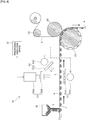
Fig. 6 is a schematic diagram illustrating the schematic configuration of the appearance inspection device; -
Fig. 7 is a schematic diagram illustrating one example of image data obtained in the state that lights are emitted from two illumination devices; and -
Fig. 8 is a schematic diagram illustrating one example of image data obtained in the state that light is emitted from only a first illumination device. - The following describes one embodiment with reference to drawings. The configuration of a PTP sheet is described first in detail.
- As shown in
Fig. 1 and Fig. 2 , aPTP sheet 1 includes acontainer film 3 having a plurality ofpocket portions 2, and acover film 4 mounted to thecontainer film 3 such as to close therespective pocket portions 2. - The
container film 3 according to the embodiment is made of a transparent or translucent thermoplastic resin material, such as PP (polypropylene) or PVC (polyvinyl chloride), and has translucency. Thecover film 4 is, on the other hand, made of an opaque material (for example, aluminum foil) with a sealant made of, for example, a polypropylene resin, provided on the surface thereof. The materials of therespective films films - The
PTP sheet 1 is manufactured by punching sheets from aPTP film 6 in a belt-like form (shown inFig. 3 ), which is comprised of thecontainer film 3 in a belt-like form and thecover film 4 in a belt-like form, and is formed in an approximately rectangular shape in plan view. In thePTP sheet 1, two pocket arrays are formed along a sheet short side direction, and each pocket array includes fivepocket portions 2 arranged along a sheet longitudinal direction. Accordingly, a total of tenpocket portions 2 are formed in thePTP sheet 1. Onetablet 5 is placed in each of thepocket portions 2. Thetablet 5 according to the embodiment is a disk-shaped plain tablet having a circular shape in plan view. - The following describes the general configuration of a
PTP packaging machine 10 used to manufacture thePTP sheet 1 described above, with reference toFig. 4 . - As shown in
Fig. 4 , a film roll of the belt-like container film 3 is wound in a roll form on a most upstream side of thePTP packaging machine 10. A pullout end of thecontainer film 3 wound in the roll form is guided by aguide roll 13. Thecontainer film 3 is then laid on anintermittent feed roll 14 provided on a downstream side of theguide roll 13. Theintermittent feed roll 14 is linked with a motor rotating in an intermittent manner, so as to convey thecontainer film 3 intermittently. - A
heating device 15 and a pocketportion forming device 16 are sequentially placed along the conveyance path of thecontainer film 3 between theguide roll 13 and theintermittent feed roll 14. In the state that thecontainer film 3 is heated to be relatively soft by theheating device 15, the plurality ofpocket portions 2 are formed at predetermined positions of thecontainer film 3 by the pocketportion forming device 16. Formation of thepocket portions 2 is performed during an interval between conveying operations of thecontainer film 3 by theintermittent feed roll 14. Theheating device 15 and the pocketportion forming device 16 are configured as the pocket portion forming unit according to the embodiment. - The
container film 3 fed from theintermittent feed roll 14 is sequentially laid on atension roll 18, aguide roll 19 and afilm receiving roll 20 in this order. Thefilm receiving roll 20 is linked with a motor rotating at a fixed speed, so as to continuously convey thecontainer film 3 at a fixed speed. Thetension roll 18 is configured to pull thecontainer film 3 in a direction of applying tension by an elastic force. This configuration prevents a slack of thecontainer film 3 due to a difference between the conveying operation by theintermittent feed roll 14 and the conveying operation by thefilm receiving roll 20 and constantly keeps thecontainer film 3 in the state of tension. - A
tablet filling device 21 and anappearance inspection device 22 are sequentially placed along the conveyance path of thecontainer film 3 between theguide roll 19 and thefilm receiving roll 20. Thetablet filling device 21 serves as the filling unit to automatically fill thepocket portions 2 with thetablets 5. Thetablet filling device 21 opens a shutter at every predetermined time interval to drop thetablet 5, in synchronization with the conveying operation of thecontainer film 3 by thefilm receiving roll 20. Each of thepocket portions 2 is filled with thetablet 5 by this shutter opening operation. - The
appearance inspection device 22 is configured to perform an inspection for adhesion of any foreign substance to thecontainer film 3. The details of theappearance inspection device 22 will be described later. - A film roll of the belt-
like cover film 4 is also wound in a roll form on a most upstream side. A pullout end of thecover film 4 wound in the roll form is guided by aguide roll 24 to aheating roll 25. - The
heating roll 25 is pressed against to be in contact with thefilm receiving roll 20 described above. Thecontainer film 3 and thecover film 4 are accordingly fed into between the tworolls container film 3 and thecover film 4 pass through between the tworolls cover film 4 is mounted to thecontainer film 3 such as to close therespective pocket portions 2. This series of operations manufactures the belt-like PTP film 6 that has thepocket portions 2 respectively filled with thetablets 5. Thefilm receiving roll 20 and theheating roll 25 are configured as the mounting unit according to the embodiment. - The
PTP film 6 fed from thefilm receiving roll 20 is sequentially laid on atension roll 27 and anintermittent feed roll 28 in this order. Theintermittent feed roll 28 is linked with a motor rotating in an intermittent manner, so as to convey thePTP film 6 intermittently. Thetension roll 27 is configured to pull thePTP film 6 in a direction of applying tension by an elastic force. This configuration prevents a slack of thePTP film 6 due to a difference between the conveying operation by thefilm receiving roll 20 and the conveying operation by theintermittent feed roll 28 and constantly keeps thePTP film 6 in the state of tension. - The
PTP film 6 fed from theintermittent feed roll 28 is sequentially laid on atension roll 31 and anintermittent feed roll 32 in this order. Theintermittent feed roll 32 is linked with a motor rotating in an intermittent manner, so as to convey thePTP film 6 intermittently. Thetension roll 31 is configured to pull thePTP film 6 in a direction of applying tension by an elastic force and thereby serves to prevent a slack of thePTP film 6 between these intermittent feed rolls 28 and 32. - A
slit formation device 33 and astamping device 34 are sequentially placed along the conveyance path of thePTP film 6 between theintermittent feed roll 28 and thetension roll 31. Theslit formation device 33 serves to form a cutting slit at predetermined positions of thePTP film 6. The stampingdevice 34 serves to stamp a mark at predetermined positions of the PTP film 6 (for example, in tag portions). The cutting slits and the marks are omitted from the illustrations ofFig. 1 and other drawings. - The
PTP film 6 fed from theintermittent feed roll 32 is sequentially laid on atension roll 35 and acontinuous feed roll 36 in this order on a downstream side of theintermittent feed roll 32. Asheet punching device 37 is placed along the conveyance path of thePTP film 6 between theintermittent feed roll 32 and thetension roll 35. Thesheet punching device 37 serves to punch out the outer periphery of each unit ofPTP sheet 1 from thePTP film 6. Thesheet punching device 37 is configured as the separation unit according to the embodiment. - The
respective PTP sheets 1 punched out by thesheet punching device 37 are conveyed by aconveyor 39 and are temporarily accumulated in afinished product hopper 40. When aPTP sheet 1 is determined as a defective product by theappearance inspection device 22 described above, however, thisPTP sheet 1 determined as defective is not conveyed to thefinished product hopper 40 but is separately discharged by a non-illustrated defective sheet discharge mechanism serving as the discharge unit. - A cutting
device 41 is provided on a downstream side of thecontinuous feed roll 36. Anunrequired film portion 42 that is a residual part (scrap part) remaining in a belt-like form after punching out by thesheet punching device 37 is guided by thetension roll 35 and thecontinuous feed roll 36 and is subsequently led to thecutting device 41. A driven roll is pressed against to be in contact with thecontinuous feed roll 36, so that theunrequired film portion 42 is placed and conveyed between the driven roll and thecontinuous feed roll 36. The cuttingdevice 41 serves to cut theunrequired film portion 42 into predetermined dimension. The cut pieces of the unrequired film portion 42 (scraps) are accumulated in ascrap hopper 43 and are then disposed separately. - Each of the rolls, for example, the
rolls pocket portions 2. The surface of each roll, for example, the surface of theintermittent feed roll 14, has recesses that are formed to place thepocket portions 2 therein. This configuration suppresses thepocket portions 2 from being crushed. The feeding operation with thepocket portions 2 placed in the respective recesses of each roll, for example, theintermittent feed roll 14, achieves the reliable intermittent feed and continuous feed. - The
PTP packaging machine 10 of the embodiment is configured to package thetablets 5 at a very high speed (for example, 8000 tablets/ minute). - The following describes the
appearance inspection device 22. Theappearance inspection device 22 is configured to perform an inspection for adhesion of any foreign substance to the container film 3 (especially, a portion that finally forms the PTP sheet 1) after thepocket portions 2 of the conveyed belt-like container film 3 are filled with thetablets 5 and before thecover film 4 is mounted to thecontainer film 3. - As shown in
Fig. 5 andFig. 6 , theappearance inspection device 22 includes afirst illumination device 51, asecond illumination device 52, an imaging device53 and aprocessing execution device 60. According to the embodiment, thefirst illumination device 51 corresponds to the first irradiation unit; thesecond illumination device 52 corresponds to the second irradiation unit; theimaging device 53 corresponds to the imaging unit; and theprocessing execution device 60 corresponds to the good/ poor quality judgment unit. - The
first illumination device 51 is placed below the conveyedcontainer film 3 and includes a firstlight source 51A that is configured by, for example, an LED to emit light such as infrared light and adiffuser plate 51B that is placed between the firstlight source 51A and thecontainer film 3 and that is configured by, for example, frosted glass. Thefirst illumination device 51 emits diffused light toward a protrusion side of thepocket portions 2 of thecontainer film 3. - The
second illumination device 52 is placed above the conveyedcontainer film 3 and includes a secondlight source 52A that is configured by, for example, an LED to emit light such as infrared light and a predetermined emission-sidepolarizing filter 52B. Thesecond illumination device 52 emits light from the secondlight source 52A through the emission-sidepolarizing filter 52B toward an opening side of thepocket portions 2 of thecontainer film 3. The light passing through the emission-sidepolarizing filter 52B becomes polarized light vibrating only in a predetermined direction. As long as the condition that thecontainer film 3 is irradiated with the light that is emitted from the secondlight source 52A and passes through the emission-sidepolarizing filter 52B, is satisfied, the positional relationship between the secondlight source 52A and the emission-sidepolarizing filter 52B may be changed appropriately. Accordingly, for example, the secondlight source 52A and the emission-sidepolarizing filter 52B may be arranged to be away from each other. - The
imaging device 53 is provided on a side opposite to thefirst illumination device 51 across thecontainer film 3 and includes acamera 53A and an imaging-sidepolarizing filter 53B. According to the embodiment, a CCD camera having sensitivity to at least infrared light is employed as thecamera 53A. Thecamera 53A is, however, not limited to the CCD camera, but a CMOS camera may be employed as thecamera 53A. - The
camera 53A performs two-dimensional imaging of thecontainer film 3 through the imaging-sidepolarizing filter 53B, while thecontainer film 3 is irradiated with the lights emitted from theillumination devices camera 53A is converted into a digital signal (image signal) inside of thecamera 53A and is input in the form of the digital signal into theprocessing execution device 60. The imaging range of thecamera 53A is set to a range that covers at least one PTP sheet 1 (a plurality of PTP sheets according to the embodiment). - The imaging-side
polarizing filter 53B is placed between thecamera 53A and thecontainer film 3 and has a polarizing direction set to a direction of shielding specularly reflected light from a container film 3-side, out of the light emitted from thesecond illumination device 52. More specifically, the polarizing direction of the imaging-sidepolarizing filter 53B is made different from a polarizing direction of the emission-sidepolarizing filter 52B by a predetermined angle or more (for example, 45 degrees or more). According to the embodiment, the polarizing direction of the imaging-sidepolarizing filter 53B is made different from the polarizing direction of the emission-sidepolarizing filter 52B by 90 degrees. - When the polarizing direction of the imaging-side
polarizing filter 53B is set as described above, specularly reflected light (light having a polarizing direction substantially identical with the polarizing direction of the light emitted from the second illumination device 52) out of the reflected light that is emitted from thesecond illumination device 52 and reflected from the container film 3-side is shielded by the imaging-sidepolarizing filter 53B and hardly enters thecamera 53A. Diffusely reflected light (light having a polarizing direction different from the polarizing direction of the light emitted from the second illumination device 52) out of the reflected light that is emitted from thesecond illumination device 52 and reflected from the container film 3-side, on the other hand, passes through the imaging-sidepolarizing filter 53B and enters thecamera 53A. - The positional relationship between the
camera 53A and the imaging-sidepolarizing filter 53B is not specifically limited as long as the condition that thecamera 53A takes an image of thecontainer film 3 through the imaging-sidepolarizing filter 53B, is satisfied. Accordingly, for example, thecamera 53A and the imaging-sidepolarizing filter 53B may be arranged to be further away from each other. - The
processing execution device 60 is configured as a so-called computer system that includes, for example, a CPU serving as the arithmetic unit, a ROM serving to store various programs, and a RAM serving to temporarily store a variety of data such as arithmetic data and input and output data. Theprocessing execution device 60 includes animage memory 61, an inspectionresult storage device 62, aquality judgment memory 63, an image and inspectionconditions storage device 64, a cameratiming control device 65, anillumination control device 66, and a CPU and input/output interface 67. - The
image memory 61 is configured to store image data obtained by thecamera 53A. An inspection is performed, based on the image data stored in thisimage memory 61. The image may be processed before the inspection is performed. For example, the image may be processed by a masking process or a shading correction. There is a technical limitation in uniformly irradiating an entire imaging range, for example, in thecontainer film 3, with the lights emitted from theillumination devices image memory 61. - The inspection
result storage device 62 is configured to, for example, good/ poor quality judgment result data and statistical data obtained by probability statistical processing of the good/ poor quality judgment result data. - The
quality judgment memory 63 is configured to store various information used for the inspection. The various information includes quality judgment criteria (for example, a threshold value) used for good/ poor quality judgment, a binarization threshold value used for a binarization process, and data for defining an inspection object range (for example, information for specifying portions corresponding to thetablets 5 in the image data and design data with regard to a positional relationship of thepocket portions 2 relative to an outer periphery of the PTP sheet 1). According to the embodiment, a luminance threshold value and an area reference value are stored as the quality judgment criteria. The luminance threshold value is used to perform good/ poor quality judgment based on the luminance, and the area reference value is used to perform good/ poor quality judgment based on the area. According to the embodiment, appropriate numerical values calculated in advance are respectively stored as the luminance threshold value and the area reference value. - The image and inspection
conditions storge device 64 is configured by, for example, a hard disk drive, to store the date and the time of each poor quality judgment and inspection conditions used for the inspection. - The camera
timing control device 65 is configured to control an imaging timing of thecamera 53A. This imaging timing is controlled on the basis of a signal from a non-illustrated encoder provided in thePTP packaging machine 10. Imaging by thecamera 53A is performed every time a predetermined amount of thecontainer film 3 is fed. - The
illumination control device 66 is configured to control the operations of thefirst illumination device 51 and thesecond illumination device 52. According to the embodiment, when a first good/ poor quality judgment described later is performed, theillumination control device 66 controls the twoillumination devices illumination devices illumination control device 66 controls the twoillumination devices first illumination device 51 and turn off thesecond illumination device 52. - The CPU and input/
output interface 67 is involved in various controls in theappearance inspection device 22. The CPU and input/output interface 67 is configured to send and receive signals to and from the respective component devices of thePTP packaging machine 10. This configuration enables, for example, the defective sheet discharge mechanism described above to be controlled. The CPU and input/output interface 67 also serves to send various data to a predetermined display unit (not shown) such as a display. This function enables various images and inspection results to be displayed on this display unit. - Furthermore, the
processing execution device 60 performs good/ poor quality judgment based on the image data obtained by thecamera 53A, with using, for example, the storage contents of thequality judgment memory 63. According to the embodiment, theprocessing execution device 60 is configured to selectively perform two different types of the good/ poor quality judgment, i.e., a first good/ poor quality judgment and a second good/ poor quality judgment. According to the embodiment, the good/ poor quality judgment to be performed by theprocessing execution device 60 is switched over by operating a predetermined switching unit (not shown). - In the case of performing the first good/ poor quality judgment, the
processing execution device 60 operates both theillumination devices container film 3 with the lights emitted from both theillumination devices camera 53A. More specifically, theprocessing execution device 60 first sets an inspection object range in the obtained image data. For example, a portion that finally forms the PTP sheet 1 (sheet portion) other than locations where thetablets 5 are present, out of an area occupied by thecontainer film 3 in the image data, is set as the inspection object range by a predetermined masking process of the obtained image data. According to a modification, a portion other than locations where thepocket portions 2 are present, out of the area occupied by thecontainer film 3 may be set as the inspection object range. - The
processing execution device 60 then determines whether any foreign substance such as hair or fiber waste adheres to thecontainer film 3, based on luminance values of respective pixels located within the set inspection object range and the luminance threshold value stored in thequality judgment memory 63. According to the embodiment, in the case where the luminance values of the respective pixels are larger than the luminance threshold value described above, theprocessing execution device 60 determines no adhesion of any foreign substance and gives a good quality judgment result. If this is not the case, theprocessing execution device 60 determines adhesion of some foreign substance and gives a poor quality judgment result. A modified procedure may divide the inspection object range into a plurality of sections, calculate a numerical value (for example, an average value or the like) on the basis of the luminance values of pixels located in each of the sections, and compare the calculated numerical value with the luminance threshold value described above, so as to make a good/ poor quality judgment with regard to adhesion of any foreign substance. Another modified procedure may calculate a luminance difference between each pair of adjacent pixels and compare the calculated luminance difference with the luminance threshold value described above, so as to make a good/ poor quality judgment. - As shown in
Fig. 7 , in the image data obtained in the state that both theillumination devices - As shown in
Fig. 8 , in the image data obtained in the state that only thefirst illumination device 51 is operated, the foreign substances F1, F2 and F3 and tablet powders K1, K2, and K3 are respectively shown as dark areas having relatively low luminance values. In the image data obtained in the state that only thesecond illumination device 52 is operated, on the other hand, the presence of the imaging-sidepolarizing filter 53B causes specularly reflected light that is reflected from the foreign substances F1, F2 and F3 to hardly enter thecamera 53A but causes diffusely reflected light that is reflected from the tablet powders K1, K2 and K3 to enter thecamera 53A. Accordingly, the foreign substances F1, F2 and F3 are shown as dark areas, and the tablet powders K1, K2 and K3 are shown as bright areas. Accordingly, in the image data obtained in the state that both theillumination devices first illumination device 51 overlap with the bright areas made by thesecond illumination device 52 at the locations where the tablet powders K1, K2 and K3 are present. As a result, this causes the locations where the tablet powders K1, K2 and K3 are present to be shown as bright areas and to become hardly recognizable in the image data. In the image data, at the locations where the foreign substances F1, F2 and F3 are present, on the other hand, the dark areas made by thefirst illumination device 51 overlap with the dark areas made by thesecond illumination device 52. As a result, these locations become distinctly recognizable as dark areas. - In the case of performing the second good/ poor quality judgment, the
processing execution device 60 operates only thefirst illumination device 51 to irradiate thecontainer film 3 with the light emitted from thefirst illumination device 51 and performs good/ poor quality judgment, based on the image data obtained by thecamera 53A (shown inFig. 8 ). More specifically, theprocessing execution device 60 first processes the image data by a binarization process using the above binarization threshold value stored in thequality judgment memory 63 to obtain binarized image data that expresses the luminance of each pixel by "0 (dark)" or "1 (bright"). Theprocessing execution device 60 then sets an inspection object range in the obtained binarized image data. The inspection object range is set by a similar procedure to the procedure in the case of performing the first good/ poor quality judgment. Theprocessing execution device 60 subsequently performs lump processing of the set inspection object range as a target. The lump processing specifies linkage components with regard to each pixel having the luminance "0 (dark)" in the binarized image data and calculates an area (the number of pixels according to the embodiment) of the specified linkage components (lump portion). Theprocessing execution device 60 then determines whether any foreign substance such as hair or fiber waste or a relatively large mass of tablet powder adheres to thecontainer film 3, based on the area of the lump portion and the above area reference value stored in thequality judgment memory 63. According to the embodiment, in the case where the areas of the respective lump portions are smaller than the area reference value described above, theprocessing execution device 60 determines no occurrence of any significant problem with regard to adhesion of any foreign substance or a large mass of tablet powder and gives a good quality judgment result. If this is not the case, theprocessing execution device 60 gives a poor quality judgment result. - In the case of performing the first good/ poor quality judgment or the second good/ poor quality judgment, a modified procedure may additionally perform an inspection for any defect of the tablet 5 (for example, a crack of the
tablet 5, inclusion of any broken piece of thetablet 5, missing of thetablet 5, or a different shape of the tablet 5), based on the obtained image data. In the case of performing the second good/ poor quality judgment, a modified procedure may perform the quality judgment based on the shape of the linkage components, in addition to or in place of the quality judgment based on the area. - As described above, the first good/ poor quality judgment ensures the good/ poor quality determination with regard to adhesion of any foreign substance by only comparing the luminance values of the image data with the luminance threshold value without requiring the lump processing, the area comparison and the like. In other words, the first good/ poor quality judgment achieves the good/ poor quality determination with regard to adhesion of any foreign substance, based on only the luminance values included in the various information obtained from the image data. The second good/ poor quality judgment, on the other hand, requires the lump processing and the area comparison but enables relatively large masses of tablet powder as well as any foreign substance to be detected.
- As described above in detail, the configuration of the embodiment described above causes only the locations where the foreign substances F1, F2 and F3 are present to be distinctly recognizable, while causing the locations where the tablet powders K1, K2 and K3 are present to be hardly recognizable in the image data obtained in the state that both the
illumination devices - Furthermore, the configuration of the embodiment does not require any complicated determination process to distinguish a foreign substance from the tablet powder and can thus sufficiently enhance the resolution of the
appearance inspection device 22 with allowing for high-speed packaging of thetablets 5. This configuration accordingly achieves both the high inspection accuracy and the high-speed production of thePTP sheet 1. - Moreover, the configuration of the embodiment requires imaging of the
container film 3 irradiated with the lights emitted from the twoillumination devices - Furthermore, the first good/ poor quality judgment ensures the good/ poor quality determination with regard to adhesion of any foreign substance, based on only the luminance values. This configuration does not require any complicated process to identify whether a foreign substance is actually present (for example, a process of specifying the area and the shape of a location where a foreign substance is expected to be present). This configuration accordingly reduces the processing load of the inspection and increases the speed of the inspection.
- Additionally, the
processing execution device 60 is allowed to perform both the first good/ poor quality judgment, which is the good/ poor quality judgment based on the image data obtained in the state of emission of the lights from both theillumination devices first illumination device 51. Theprocessing execution device 60 is also allowed to perform selected one of the first good/ poor quality judgment and the second good/ poor quality judgment. For example, theprocessing execution device 60 may select the first good/ poor quality judgment for an inspection in a system of not taking into account the tablet powder and may select the second good/ poor quality judgment for an inspection in a system of taking into account the tablet powder (for example, a large mass or a small mass of the tablet powder). This configuration does not require separate devices provided for performing the respective good/ poor quality judgments and thereby suppresses a cost increase, while broadening the options of the inspection technique. - The polarizing direction of the imaging-side
polarizing filter 53B is made different from the polarizing direction of the emission-sidepolarizing filter 52B by 90 degrees. This arrangement enables specularly reflected light that is reflected from a foreign substance to be more reliably shielded by the imaging-sidepolarizing filter 53B. This configuration accordingly enables only the location where a foreign substance is present to be made more distinctly recognizable in the obtained image data and enables the inspection for adhesion of any foreign substance to be performed with the higher accuracy. - The present disclosure is not limited to the description of the above embodiment but may be implemented, for example, by configurations described below. The present disclosure may also be naturally implemented by applications and modifications other than those illustrated below.
- (a) The above embodiment is configured to perform the second good/ poor quality judgment, based on the image data obtained with emission of the light from the
first illumination device 51. A modification may be configured to perform the second good/ poor quality judgment, based on the image data obtained with emission of the light from thesecond illumination device 52. - (b) According to the embodiment described above, the
tablet 5 is the disk-shaped plain tablet (disk-shaped flat tablet) having the circular shape in plan view. The type, the shape and the like of the tablet are, however, not limited to those of the above embodiment. For example, the tablet is not limited to medicinal tablets but includes, for example, food tablets. The tablet is not limited to the plain tablets but includes, for example, orally disintegrating tablets and enteric coated tablets.
Furthermore, the shape of the tablet is not limited to the circular shape in plan view but may be a polygonal shape in plan view, an oval shape in plan view or an elliptical shape in plan view. - (c) The arrangement and the number of the
pocket portions 2 in the PTP sheet are not limited to those of the above embodiment (two arrays and a total of ten pocket portions), but a PTP sheet may employ any of various arrangements and various numbers of the pocket portions, for example, three arrays and a total of twelve pocket portions. - According to the embodiment described above, the
PTP film 6 is configured to have the number ofpocket portions 2 arrayed corresponding to one sheet along its width direction. The arrangement is, however, not limited to this configuration. For example, the PTP film may be configured to have the number ofpocket portions 2 arrayed corresponding to multiple sheets along its width direction. - 1... PTP sheet, 2... pocket portion, 3... container film, 4... cover film, 5... tablet, 10... PTP packaging machine, 22... appearance inspection device, 51... first illumination device (first irradiation unit), 51A... first light source, 52... second illumination device (second irradiation unit), 52A... second light source, 52B... emission-side polarizing filter, 53... imaging device (imaging unit), 53B... imaging-side polarizing filter, 60... processing execution device (good/ poor quality judgment unit)
Claims (5)
- An appearance inspection device used in a process of manufacturing a PTP sheet configured such that a tablet is placed in a pocket portion formed in a container film and that a cover film is mounted to the container film so as to close the pocket portion, the appearance inspection device being configured to perform an inspection for adhesion of a foreign substance to the container film in a stage after the pocket portion of the container film conveyed in a belt-like form is filled with the tablet and before the cover film is mounted to the container film,
the appearance inspection device comprising:an imaging unit provided with a predetermined imaging-side polarizing filter and configured to take an image of the container film through the imaging-side polarizing filter;a first irradiation unit placed on a side opposite to the imaging unit across the container film, provided with a predetermined first light source, and configured to emit light from the first light source toward a protrusion side of the pocket portion in the container film;a second irradiation unit provided with a predetermined second light source and a predetermined emission-side polarizing filter and configured to emit light from the second light source through the emission-side polarizing filter toward an opening side of the pocket portion in the container film; anda good/ poor quality judgment unit configured to perform a good/ poor quality judgment with regard to adhesion of a foreign substance, based on image data obtained by the imaging unit, whereinthe imaging-side polarizing filter has a polarizing direction set to a direction of shielding specularly reflected light from a container film-side out of the light emitted from the second irradiation unit, andthe imaging unit is configured to take an image of the container film that is irradiated with the lights emitted from the first irradiation unit and the second irradiation unit. - The appearance inspection device according to claim 1,
wherein the good/ poor quality judgment unit is configured to perform the good/ poor quality judgment with regard to adhesion of the foreign substance, based on only a luminance value included in the image data obtained by the imaging unit. - The appearance inspection device according to either claim 1 or claim 2,
wherein the good/ poor quality judgment unit is configured to perform:a first good/ poor quality judgment that is a good/ poor quality judgment based on image data obtained by imaging the container film by the imaging unit in a state that the container film is irradiated with lights emitted from both the first irradiation unit and the second irradiation unit; anda second good/ poor quality judgment that is a good/ poor quality judgment based on image data obtained by imaging the container film by the imaging unit in a state that the container film is irradiated with light emitted from one of the first irradiation unit and the second irradiation unit, andthe good/ poor quality judgment unit is configured to perform a good/ poor quality judgment selected between the first good/ poor quality judgment and the second good/ poor quality judgment. - The appearance inspection device according to any one of claims 1 to 3,
wherein the polarizing direction of the imaging-side polarizing filter is different from a polarizing direction of the emission-side polarizing filter by 90 degrees. - A PTP packaging machine, comprising:
the appearance inspection device according to any one of claims 1 to 4.
Applications Claiming Priority (2)
| Application Number | Priority Date | Filing Date | Title |
|---|---|---|---|
| JP2018173505A JP6606244B1 (en) | 2018-09-18 | 2018-09-18 | Appearance inspection device and PTP packaging machine |
| PCT/JP2019/021676 WO2020059214A1 (en) | 2018-09-18 | 2019-05-31 | Appearance inspection device and ptp packaging machine |
Publications (3)
| Publication Number | Publication Date |
|---|---|
| EP3855171A1 true EP3855171A1 (en) | 2021-07-28 |
| EP3855171A4 EP3855171A4 (en) | 2022-06-22 |
| EP3855171B1 EP3855171B1 (en) | 2025-12-24 |
Family
ID=68532225
Family Applications (1)
| Application Number | Title | Priority Date | Filing Date |
|---|---|---|---|
| EP19862827.3A Active EP3855171B1 (en) | 2018-09-18 | 2019-05-31 | Appearance inspection device and ptp packaging machine |
Country Status (5)
| Country | Link |
|---|---|
| EP (1) | EP3855171B1 (en) |
| JP (1) | JP6606244B1 (en) |
| KR (1) | KR102605309B1 (en) |
| CN (1) | CN112585452B (en) |
| WO (1) | WO2020059214A1 (en) |
Families Citing this family (2)
| Publication number | Priority date | Publication date | Assignee | Title |
|---|---|---|---|---|
| JP7317286B2 (en) * | 2018-12-20 | 2023-07-31 | 住友ゴム工業株式会社 | Defect detection device with rubber on topping rubber sheet |
| JP7066026B1 (en) * | 2021-04-07 | 2022-05-12 | Ckd株式会社 | Manufacturing method for inspection equipment, blister packaging machines and blister packs |
Family Cites Families (17)
| Publication number | Priority date | Publication date | Assignee | Title |
|---|---|---|---|---|
| JP2530532B2 (en) * | 1991-08-22 | 1996-09-04 | シーケーディ株式会社 | Tablet sheet inspection device |
| JPH08271433A (en) * | 1995-03-30 | 1996-10-18 | Nikon Corp | Tablet inspection device |
| JP3585305B2 (en) * | 1996-01-11 | 2004-11-04 | 富士写真フイルム株式会社 | Inspection device for foreign substances inside transparent support |
| JPH1115970A (en) * | 1997-06-26 | 1999-01-22 | Ishikawajima Harima Heavy Ind Co Ltd | Method and apparatus for inspecting foreign matter in glass substrate TAB bonding portion |
| JP4173257B2 (en) * | 1999-09-06 | 2008-10-29 | シーケーディ株式会社 | Sheet visual inspection device and PTP packaging machine |
| JP2001349837A (en) * | 2000-06-12 | 2001-12-21 | Kirin Techno-System Corp | PTP preparation inspection apparatus and inspection method |
| JP4034033B2 (en) * | 2000-08-08 | 2008-01-16 | シーケーディ株式会社 | Tablet appearance inspection device and PTP packaging machine |
| BE1014410A3 (en) * | 2001-10-03 | 2003-10-07 | Geert Coudijzer | Detection device for presence or properties of objects in blister packaging, illuminates blister pockets from their open and closed sides |
| JP4368808B2 (en) * | 2005-01-07 | 2009-11-18 | シーケーディ株式会社 | Appearance inspection device and PTP packaging machine |
| JP4173184B2 (en) * | 2007-07-04 | 2008-10-29 | ライオンエンジニアリング株式会社 | PTP package appearance inspection equipment |
| KR20090024943A (en) * | 2007-09-05 | 2009-03-10 | 아주하이텍(주) | Automatic optical inspection device and method |
| JP4994183B2 (en) * | 2007-10-22 | 2012-08-08 | シーケーディ株式会社 | PTP packaging machine |
| JP5697168B2 (en) * | 2012-08-07 | 2015-04-08 | Ckd株式会社 | Inspection device and PTP packaging machine |
| JP5921704B2 (en) * | 2014-03-10 | 2016-05-24 | 株式会社東芝 | Foreign matter inspection device, foreign matter inspection method, foreign matter inspection program |
| SG10201501672PA (en) * | 2015-03-05 | 2016-10-28 | Emage Vision Pte Ltd | Inspection of sealing quality in blister packages |
| JP6653958B2 (en) * | 2016-01-29 | 2020-02-26 | 東罐興業株式会社 | Image inspection system, imaging system, and imaging method |
| JP6862155B2 (en) * | 2016-11-24 | 2021-04-21 | 第一実業ビスウィル株式会社 | Visual inspection equipment |
-
2018
- 2018-09-18 JP JP2018173505A patent/JP6606244B1/en active Active
-
2019
- 2019-05-31 WO PCT/JP2019/021676 patent/WO2020059214A1/en not_active Ceased
- 2019-05-31 EP EP19862827.3A patent/EP3855171B1/en active Active
- 2019-05-31 CN CN201980053847.7A patent/CN112585452B/en active Active
- 2019-05-31 KR KR1020217009656A patent/KR102605309B1/en active Active
Also Published As
| Publication number | Publication date |
|---|---|
| JP2020046244A (en) | 2020-03-26 |
| KR20210058864A (en) | 2021-05-24 |
| JP6606244B1 (en) | 2019-11-13 |
| EP3855171A4 (en) | 2022-06-22 |
| EP3855171B1 (en) | 2025-12-24 |
| WO2020059214A1 (en) | 2020-03-26 |
| KR102605309B1 (en) | 2023-11-22 |
| CN112585452A (en) | 2021-03-30 |
| CN112585452B (en) | 2024-12-20 |
Similar Documents
| Publication | Publication Date | Title |
|---|---|---|
| US10926907B2 (en) | PTP packaging machine | |
| CN111033241B (en) | Appearance inspection device and blister packaging machine | |
| JP6411599B1 (en) | Blister packing machine | |
| EP3614127B1 (en) | Inspection device, ptp packaging machine, and ptp sheet manufacturing method | |
| CN105292620B (en) | inspection device and PTP packaging machine | |
| EP3805740B1 (en) | Inspecting device, and ptp packing machine | |
| US11994477B2 (en) | Inspection device, packaging sheet manufacturing device, and inspection method | |
| JP6613353B2 (en) | Appearance inspection device and blister packaging machine | |
| JP2016003903A (en) | Inspection system and PTP packaging machine | |
| EP3859311B1 (en) | Inspection apparatus, ptp packaging machine, and method for manufacturing ptp sheet | |
| EP3855171B1 (en) | Appearance inspection device and ptp packaging machine | |
| JP6062102B1 (en) | Inspection device and PTP packaging machine | |
| JP6046585B2 (en) | Inspection device and PTP packaging machine | |
| EP3608655A1 (en) | Testing device, ptp packaging machine, and method for manufacturing ptp sheets | |
| CN110589122B (en) | Inspection device, PTP packaging machine, and manufacturing method of PTP sheet | |
| CN110775374B (en) | Inspection device, PTP packaging machine, and manufacturing method of PTP sheet | |
| JP2017156183A (en) | Inspection device and blister packaging machine | |
| JP2024076420A (en) | Inspection equipment and blister packing machines |
Legal Events
| Date | Code | Title | Description |
|---|---|---|---|
| STAA | Information on the status of an ep patent application or granted ep patent |
Free format text: STATUS: THE INTERNATIONAL PUBLICATION HAS BEEN MADE |
|
| PUAI | Public reference made under article 153(3) epc to a published international application that has entered the european phase |
Free format text: ORIGINAL CODE: 0009012 |
|
| STAA | Information on the status of an ep patent application or granted ep patent |
Free format text: STATUS: REQUEST FOR EXAMINATION WAS MADE |
|
| 17P | Request for examination filed |
Effective date: 20210126 |
|
| AK | Designated contracting states |
Kind code of ref document: A1 Designated state(s): AL AT BE BG CH CY CZ DE DK EE ES FI FR GB GR HR HU IE IS IT LI LT LU LV MC MK MT NL NO PL PT RO RS SE SI SK SM TR |
|
| DAV | Request for validation of the european patent (deleted) | ||
| DAX | Request for extension of the european patent (deleted) | ||
| A4 | Supplementary search report drawn up and despatched |
Effective date: 20220519 |
|
| RIC1 | Information provided on ipc code assigned before grant |
Ipc: G01N 21/90 20060101ALI20220513BHEP Ipc: G01N 21/892 20060101ALI20220513BHEP Ipc: B65B 57/10 20060101ALI20220513BHEP Ipc: B65B 47/02 20060101ALI20220513BHEP Ipc: G01N 21/89 20060101AFI20220513BHEP |
|
| STAA | Information on the status of an ep patent application or granted ep patent |
Free format text: STATUS: EXAMINATION IS IN PROGRESS |
|
| 17Q | First examination report despatched |
Effective date: 20230705 |
|
| GRAP | Despatch of communication of intention to grant a patent |
Free format text: ORIGINAL CODE: EPIDOSNIGR1 |
|
| STAA | Information on the status of an ep patent application or granted ep patent |
Free format text: STATUS: GRANT OF PATENT IS INTENDED |
|
| INTG | Intention to grant announced |
Effective date: 20250724 |
|
| GRAS | Grant fee paid |
Free format text: ORIGINAL CODE: EPIDOSNIGR3 |
|
| GRAA | (expected) grant |
Free format text: ORIGINAL CODE: 0009210 |
|
| STAA | Information on the status of an ep patent application or granted ep patent |
Free format text: STATUS: THE PATENT HAS BEEN GRANTED |
|
| AK | Designated contracting states |
Kind code of ref document: B1 Designated state(s): AL AT BE BG CH CY CZ DE DK EE ES FI FR GB GR HR HU IE IS IT LI LT LU LV MC MK MT NL NO PL PT RO RS SE SI SK SM TR |
|
| RAP3 | Party data changed (applicant data changed or rights of an application transferred) |
Owner name: CKD CORPORATION |
|
| REG | Reference to a national code |
Ref country code: CH Ref legal event code: F10 Free format text: ST27 STATUS EVENT CODE: U-0-0-F10-F00 (AS PROVIDED BY THE NATIONAL OFFICE) Effective date: 20251224 Ref country code: GB Ref legal event code: FG4D |
|
| REG | Reference to a national code |
Ref country code: DE Ref legal event code: R096 Ref document number: 602019079662 Country of ref document: DE |
|
| REG | Reference to a national code |
Ref country code: LT Ref legal event code: MG9D |
|
| PG25 | Lapsed in a contracting state [announced via postgrant information from national office to epo] |
Ref country code: NO Free format text: LAPSE BECAUSE OF FAILURE TO SUBMIT A TRANSLATION OF THE DESCRIPTION OR TO PAY THE FEE WITHIN THE PRESCRIBED TIME-LIMIT Effective date: 20260324 |
|
| PG25 | Lapsed in a contracting state [announced via postgrant information from national office to epo] |
Ref country code: FI Free format text: LAPSE BECAUSE OF FAILURE TO SUBMIT A TRANSLATION OF THE DESCRIPTION OR TO PAY THE FEE WITHIN THE PRESCRIBED TIME-LIMIT Effective date: 20251224 Ref country code: HR Free format text: LAPSE BECAUSE OF FAILURE TO SUBMIT A TRANSLATION OF THE DESCRIPTION OR TO PAY THE FEE WITHIN THE PRESCRIBED TIME-LIMIT Effective date: 20251224 |
|
| PG25 | Lapsed in a contracting state [announced via postgrant information from national office to epo] |
Ref country code: RS Free format text: LAPSE BECAUSE OF FAILURE TO SUBMIT A TRANSLATION OF THE DESCRIPTION OR TO PAY THE FEE WITHIN THE PRESCRIBED TIME-LIMIT Effective date: 20260324 |
|
| PG25 | Lapsed in a contracting state [announced via postgrant information from national office to epo] |
Ref country code: LV Free format text: LAPSE BECAUSE OF FAILURE TO SUBMIT A TRANSLATION OF THE DESCRIPTION OR TO PAY THE FEE WITHIN THE PRESCRIBED TIME-LIMIT Effective date: 20251224 |
|
| REG | Reference to a national code |
Ref country code: NL Ref legal event code: MP Effective date: 20251224 |
|
| PG25 | Lapsed in a contracting state [announced via postgrant information from national office to epo] |
Ref country code: BG Free format text: LAPSE BECAUSE OF FAILURE TO SUBMIT A TRANSLATION OF THE DESCRIPTION OR TO PAY THE FEE WITHIN THE PRESCRIBED TIME-LIMIT Effective date: 20251224 |
|
| REG | Reference to a national code |
Ref country code: AT Ref legal event code: MK05 Ref document number: 1871162 Country of ref document: AT Kind code of ref document: T Effective date: 20251224 |
|
| PG25 | Lapsed in a contracting state [announced via postgrant information from national office to epo] |
Ref country code: NL Free format text: LAPSE BECAUSE OF FAILURE TO SUBMIT A TRANSLATION OF THE DESCRIPTION OR TO PAY THE FEE WITHIN THE PRESCRIBED TIME-LIMIT Effective date: 20251224 |
|
| PG25 | Lapsed in a contracting state [announced via postgrant information from national office to epo] |
Ref country code: LT Free format text: LAPSE BECAUSE OF FAILURE TO SUBMIT A TRANSLATION OF THE DESCRIPTION OR TO PAY THE FEE WITHIN THE PRESCRIBED TIME-LIMIT Effective date: 20251224 |
|
| PG25 | Lapsed in a contracting state [announced via postgrant information from national office to epo] |
Ref country code: SM Free format text: LAPSE BECAUSE OF FAILURE TO SUBMIT A TRANSLATION OF THE DESCRIPTION OR TO PAY THE FEE WITHIN THE PRESCRIBED TIME-LIMIT Effective date: 20251224 |
|
| PG25 | Lapsed in a contracting state [announced via postgrant information from national office to epo] |
Ref country code: ES Free format text: LAPSE BECAUSE OF FAILURE TO SUBMIT A TRANSLATION OF THE DESCRIPTION OR TO PAY THE FEE WITHIN THE PRESCRIBED TIME-LIMIT Effective date: 20251224 |
|
| PG25 | Lapsed in a contracting state [announced via postgrant information from national office to epo] |
Ref country code: PL Free format text: LAPSE BECAUSE OF FAILURE TO SUBMIT A TRANSLATION OF THE DESCRIPTION OR TO PAY THE FEE WITHIN THE PRESCRIBED TIME-LIMIT Effective date: 20251224 |
|
| PGFP | Annual fee paid to national office [announced via postgrant information from national office to epo] |
Ref country code: GB Payment date: 20260521 Year of fee payment: 8 |
|
| PGFP | Annual fee paid to national office [announced via postgrant information from national office to epo] |
Ref country code: IT Payment date: 20260529 Year of fee payment: 8 |
|
| PGFP | Annual fee paid to national office [announced via postgrant information from national office to epo] |
Ref country code: DE Payment date: 20260415 Year of fee payment: 8 |
|
| PG25 | Lapsed in a contracting state [announced via postgrant information from national office to epo] |
Ref country code: AT Free format text: LAPSE BECAUSE OF FAILURE TO SUBMIT A TRANSLATION OF THE DESCRIPTION OR TO PAY THE FEE WITHIN THE PRESCRIBED TIME-LIMIT Effective date: 20251224 |
|
| PG25 | Lapsed in a contracting state [announced via postgrant information from national office to epo] |
Ref country code: EE Free format text: LAPSE BECAUSE OF FAILURE TO SUBMIT A TRANSLATION OF THE DESCRIPTION OR TO PAY THE FEE WITHIN THE PRESCRIBED TIME-LIMIT Effective date: 20251224 |
|
| PG25 | Lapsed in a contracting state [announced via postgrant information from national office to epo] |
Ref country code: PT Free format text: LAPSE BECAUSE OF FAILURE TO SUBMIT A TRANSLATION OF THE DESCRIPTION OR TO PAY THE FEE WITHIN THE PRESCRIBED TIME-LIMIT Effective date: 20260424 Ref country code: IS Free format text: LAPSE BECAUSE OF FAILURE TO SUBMIT A TRANSLATION OF THE DESCRIPTION OR TO PAY THE FEE WITHIN THE PRESCRIBED TIME-LIMIT Effective date: 20260424 |
|
| PG25 | Lapsed in a contracting state [announced via postgrant information from national office to epo] |
Ref country code: CZ Free format text: LAPSE BECAUSE OF FAILURE TO SUBMIT A TRANSLATION OF THE DESCRIPTION OR TO PAY THE FEE WITHIN THE PRESCRIBED TIME-LIMIT Effective date: 20251224 |
|
| PGFP | Annual fee paid to national office [announced via postgrant information from national office to epo] |
Ref country code: FR Payment date: 20260522 Year of fee payment: 8 |
|
| PG25 | Lapsed in a contracting state [announced via postgrant information from national office to epo] |
Ref country code: SK Free format text: LAPSE BECAUSE OF FAILURE TO SUBMIT A TRANSLATION OF THE DESCRIPTION OR TO PAY THE FEE WITHIN THE PRESCRIBED TIME-LIMIT Effective date: 20251224 |
|
| PG25 | Lapsed in a contracting state [announced via postgrant information from national office to epo] |
Ref country code: SE Free format text: LAPSE BECAUSE OF FAILURE TO SUBMIT A TRANSLATION OF THE DESCRIPTION OR TO PAY THE FEE WITHIN THE PRESCRIBED TIME-LIMIT Effective date: 20251224 |