EP3855016B1 - Parc éolien - Google Patents
Parc éolien Download PDFInfo
- Publication number
- EP3855016B1 EP3855016B1 EP19863808.2A EP19863808A EP3855016B1 EP 3855016 B1 EP3855016 B1 EP 3855016B1 EP 19863808 A EP19863808 A EP 19863808A EP 3855016 B1 EP3855016 B1 EP 3855016B1
- Authority
- EP
- European Patent Office
- Prior art keywords
- wind
- wind power
- power generator
- slipstream
- windward side
- Prior art date
- Legal status (The legal status is an assumption and is not a legal conclusion. Google has not performed a legal analysis and makes no representation as to the accuracy of the status listed.)
- Active
Links
- 238000012545 processing Methods 0.000 description 38
- 238000005259 measurement Methods 0.000 description 24
- 238000010586 diagram Methods 0.000 description 12
- 238000000034 method Methods 0.000 description 12
- 238000010248 power generation Methods 0.000 description 12
- 239000013643 reference control Substances 0.000 description 6
- 230000007704 transition Effects 0.000 description 5
- 230000008859 change Effects 0.000 description 4
- 238000006243 chemical reaction Methods 0.000 description 4
- 238000009499 grossing Methods 0.000 description 4
- 238000010606 normalization Methods 0.000 description 4
- 238000009434 installation Methods 0.000 description 3
- 230000008569 process Effects 0.000 description 3
- 230000005540 biological transmission Effects 0.000 description 2
- 230000007423 decrease Effects 0.000 description 2
- 230000000694 effects Effects 0.000 description 2
- 210000003746 feather Anatomy 0.000 description 2
- 230000006872 improvement Effects 0.000 description 2
- 238000005457 optimization Methods 0.000 description 2
- 230000004931 aggregating effect Effects 0.000 description 1
- 238000011156 evaluation Methods 0.000 description 1
- 239000011159 matrix material Substances 0.000 description 1
- 230000004044 response Effects 0.000 description 1
Images


Classifications
-
- F—MECHANICAL ENGINEERING; LIGHTING; HEATING; WEAPONS; BLASTING
- F03—MACHINES OR ENGINES FOR LIQUIDS; WIND, SPRING, OR WEIGHT MOTORS; PRODUCING MECHANICAL POWER OR A REACTIVE PROPULSIVE THRUST, NOT OTHERWISE PROVIDED FOR
- F03D—WIND MOTORS
- F03D7/00—Controlling wind motors
- F03D7/02—Controlling wind motors the wind motors having rotation axis substantially parallel to the air flow entering the rotor
- F03D7/04—Automatic control; Regulation
- F03D7/042—Automatic control; Regulation by means of an electrical or electronic controller
- F03D7/048—Automatic control; Regulation by means of an electrical or electronic controller controlling wind farms
-
- F—MECHANICAL ENGINEERING; LIGHTING; HEATING; WEAPONS; BLASTING
- F03—MACHINES OR ENGINES FOR LIQUIDS; WIND, SPRING, OR WEIGHT MOTORS; PRODUCING MECHANICAL POWER OR A REACTIVE PROPULSIVE THRUST, NOT OTHERWISE PROVIDED FOR
- F03D—WIND MOTORS
- F03D7/00—Controlling wind motors
- F03D7/02—Controlling wind motors the wind motors having rotation axis substantially parallel to the air flow entering the rotor
- F03D7/0204—Controlling wind motors the wind motors having rotation axis substantially parallel to the air flow entering the rotor for orientation in relation to wind direction
-
- F—MECHANICAL ENGINEERING; LIGHTING; HEATING; WEAPONS; BLASTING
- F03—MACHINES OR ENGINES FOR LIQUIDS; WIND, SPRING, OR WEIGHT MOTORS; PRODUCING MECHANICAL POWER OR A REACTIVE PROPULSIVE THRUST, NOT OTHERWISE PROVIDED FOR
- F03D—WIND MOTORS
- F03D7/00—Controlling wind motors
- F03D7/02—Controlling wind motors the wind motors having rotation axis substantially parallel to the air flow entering the rotor
- F03D7/022—Adjusting aerodynamic properties of the blades
- F03D7/0224—Adjusting blade pitch
-
- F—MECHANICAL ENGINEERING; LIGHTING; HEATING; WEAPONS; BLASTING
- F05—INDEXING SCHEMES RELATING TO ENGINES OR PUMPS IN VARIOUS SUBCLASSES OF CLASSES F01-F04
- F05B—INDEXING SCHEME RELATING TO WIND, SPRING, WEIGHT, INERTIA OR LIKE MOTORS, TO MACHINES OR ENGINES FOR LIQUIDS COVERED BY SUBCLASSES F03B, F03D AND F03G
- F05B2270/00—Control
- F05B2270/10—Purpose of the control system
- F05B2270/20—Purpose of the control system to optimise the performance of a machine
- F05B2270/204—Purpose of the control system to optimise the performance of a machine taking into account the wake effect
-
- Y—GENERAL TAGGING OF NEW TECHNOLOGICAL DEVELOPMENTS; GENERAL TAGGING OF CROSS-SECTIONAL TECHNOLOGIES SPANNING OVER SEVERAL SECTIONS OF THE IPC; TECHNICAL SUBJECTS COVERED BY FORMER USPC CROSS-REFERENCE ART COLLECTIONS [XRACs] AND DIGESTS
- Y02—TECHNOLOGIES OR APPLICATIONS FOR MITIGATION OR ADAPTATION AGAINST CLIMATE CHANGE
- Y02E—REDUCTION OF GREENHOUSE GAS [GHG] EMISSIONS, RELATED TO ENERGY GENERATION, TRANSMISSION OR DISTRIBUTION
- Y02E10/00—Energy generation through renewable energy sources
- Y02E10/70—Wind energy
- Y02E10/72—Wind turbines with rotation axis in wind direction
Definitions
- the present invention relates to a wind farm, in which a plurality of wind power generators are installed, and a wind power generator, and in particular, relates to a wind farm capable of improving a power generation amount of an entire wind farm and a wind power generator suited to be installed in the wind farm.
- wind called a wind turbine slipstream (simply referred to as a slipstream) that has passed through the wind power generator located on a windward side flows into the wind power generator on a leeward side.
- a wind turbine slipstream there are drawbacks such as a decrease in the power generation amount of the wind power generator, an increase in damage degree of the wind power generator, and the like.
- a method for controlling an inclination angle of a blade of the wind power generator located on the windward side a method for controlling an orientation of a rotational plane of a rotor, and the like have been proposed.
- PTL 1 discloses a method for controlling the inclination angle (pitch angle) of the blade of the wind power generator located on the windward side, and describes, in a wind farm including a plurality of wind power generators (T1, Ti-1, Ti), a configuration for adjusting operation parameters of the wind power generators (T1, Ti-1, Ti) according to an optimization target during the operation of the wind farm. Then, PTL 1 discloses that the above optimization target is set to the maximum value of the total output of the wind farm formed from the sum of all the individual outputs (Pi) of the plurality of wind power generators (T1, Ti-1, Ti).
- PTL 2 describes a wind farm including a plurality of wind power generators each including at least a rotor that rotates by receiving the wind and a yaw angle controller for controlling the orientation of the rotational plane of the rotor, and a controller for determining a slipstream region based on wind direction data and information of the orientation of the rotational plane of the rotor of the wind power generator located on the windward side, and controlling the orientation of the rotational plane of the rotor of the wind power generator located on the windward side, based on the slipstream region that has been determined and position information of the wind power generator located on the leeward side.
- the present invention provides a wind farm and a wind power generator capable of improving the power generation amount of the entire wind farm without introducing a central processing unit of the wind farm.
- a wind farm according to the present invention includes the subjectmatter defined in claim 1.
- the present invention it is possible to provide a wind farm and a wind power generator capable of improving the power generation amount of the entire wind farm without introducing a central processing unit of the wind farm.
- a downwind type of a wind power generator will be described as an example, but the present invention is applicable to an upwind type of a wind power generator.
- a rotor is composed of three blades and a hub is shown, but the present invention is not limited to this, and the rotor may be composed of a hub and at least one blade.
- a wind farm in which a plurality of wind power generators according to embodiments of the present invention are installed to be adjacent to each other can be provided at any place of offshore, mountainous, and plain areas.
- FIG. 1 is an overall schematic configuration diagram showing an example of the wind power generator in the first embodiment.
- a wind power generator 2 includes blades 23 that rotate by receiving wind, a hub 22 that supports the blades 23, a nacelle 21, and a tower 20 that supports the nacelle 21 to be rotatable.
- a main shaft 25 connected with the hub 22 and rotating together with the hub 22, a speed increaser 27 connected with the main shaft 25 to increase a rotation speed, and a generator 28 that rotates a rotor at a rotation speed that has been increased by the speed increaser 27 to generate power.
- an installation orientation of the blades 23 is referred to as a pitch angle
- the wind power generator 2 includes a pitch angle controller 34 that controls the pitch angle, that is, the orientation of the blades 23.
- a part that transmits the rotational energy of the blades 23 to the generator 28 is referred to as a power transmission unit.
- the main shaft 25 and the speed increaser 27 are included in the power transmission unit.
- the speed increaser 27 and the generator 28 are held on a main frame 29, and the generator 28 includes a power generator controller 35 that controls a movement of the generator 28.
- a rotor 24 is composed of the blades 23 and the hub 22.
- a power converter 30 that converts the frequency of electric power, a switch and a transformer for switching to open and close electric current (not shown), a controller 31, and the like are arranged in the tower 20.
- the power converter 30 and the controller 31 are installed at the bottom of the tower.
- the installation locations of these devices are not limited to the bottom of the tower. As long as the installation locations are inside the wind power generator 2, it is also conceivable that the power converter 30 and the controller 31 are installed at another location.
- a wind direction anemometer 32 that measures wind direction data and wind speed data is installed on an upper surface of the nacelle 21.
- the controller 31 for example, a control panel or SCADA (Supervisory Control And Data Acquisition) is used.
- an orientation of the nacelle 21 is referred to as a yaw angle
- the wind power generator 2 includes a yaw angle controller 33 that controls the orientation of the nacelle 21, that is, an orientation of the rotational plane of the rotor 24.
- the yaw angle controller 33 is arranged between a bottom surface of the nacelle 21 and a tip end portion of the tower 20, and is composed of, for example, at least an actuator and a motor for driving the actuator, which are not shown.
- the motor constituting the yaw angle controller 33 rotates, based on a yaw angle control command output from the controller 31 via a signal line, the actuator is displaced by a desired amount, and the nacelle 21 rotates to have a desired yaw angle.
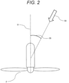
- FIG. 2 is a schematic diagram showing an example of a relationship between the wind power generator and the wind direction.
- a deviation between a nacelle direction 51, which corresponds to an orientation of the wind power generator 2, and a wind direction 53 is referred to as a yaw error 55.
- the nacelle direction 51 is controlled by the yaw angle controller 33 so that the yaw error 55 becomes smaller.
- FIG. 3 is a diagram showing an example of a relationship between a wind power generator located on the windward side and a wind power generator located on the leeward side that are installed in the wind farm.
- FIG. 3 shows an example in which the wind that has passed through a wind power generator 2a, which is installed in the wind farm 1 and which is located on the windward side, flows into a wind power generator 2b located on the leeward side.
- the wind that has passed through the wind power generator 2a located on the windward side is referred to as a wind turbine slipstream (simply referred to as a slipstream).
- a wind turbine slipstream wind characteristics such as a wind direction and a wind speed change as compared with those before the wind flows into the wind power generator 2a located on the windward side.
- Such changes in the characteristics depend on an operating state of the wind power generator 2a located on the windward side.
- the operating state described here includes an inclination angle (the pitch angle) of the blades 23 of the wind power generator or the orientation of the rotational plane of the rotor 24.
- FIG. 4 is a top view showing an example of a small-sized wind farm including a wind power generator located on the windward side and a wind power generator located on the leeward side.
- FIG. 5 is a top view showing an example of a large-sized wind farm including a large number of wind power generators.
- FIG. 4 shows an example of a small-sized wind farm 1 including the wind power generator 2a located on the windward side and the wind power generator 2b located on the leeward side.
- FIG. 5 shows an example of a large-sized wind farm 1 including the wind power generator 2a located on the windward side, the wind power generator 2b located on the leeward side, a wind power generator 2c partially influenced by the wind turbine slipstream, and a large number of wind power generators 2d.
- the wind farm 1 described here refers to an aggregated type of wind power plant or a wind power generator group including at least two or more wind power generators.
- the wind power generators 2 installed in the wind farm 1 are classified, with respect to the wind direction, into the wind power generator 2a located on the windward side, the wind power generator 2b located on the leeward side, the wind power generator 2c partially influenced by the wind turbine slipstream, and the other wind power generators 2d, and this classification changes as the wind direction changes. Specifically, in the example of FIG. 5 , the wind turbine slipstream generated by the wind power generator 2a located on the windward side flows into the wind power generator 2b located on the leeward side.
- the wind power generator 2b, the wind power generator 2c, or the wind power generator 2d which are located on the leeward side, plays a role similar to that of the wind power generator 2a located on the windward side, or a case where the wind power generator 2a, the wind power generator 2c, or the wind power generator 2d, which are located on the windward side, play a role similar to that of the wind power generator 2b located on the leeward side.
- the wind turbine slipstream (slipstream) will be described.
- the wind that passes through the wind power generator 2a located on the windward side changes in wind conditions such as the wind direction and the wind speed due to an influence of the rotation of the rotor 24 constituting the wind power generator 2a located on the windward side.
- the wind conditions that change in this situation are not limited to the above-mentioned wind direction and wind speed. All physical quantities related to the wind such as turbulent flow characteristics and vortex shapes, which are turbulence forms of the wind, can be considered.
- the wind turbine slipstream passes through the wind power generator 2a located on the windward side, and then spreads and flows to the leeward side.
- the wind turbine slipstream propagates to the leeward side while diffusing and generating vortices (turbulence).
- a region in which the wind turbine slipstream propagates to the leeward side while diffusing and generating vortices (turbulence) in this manner is hereinafter referred to as a wind turbine slipstream region (also referred to as a slipstream region).
- the power generation amount is lower than that of the wind power generator 2d located outside the wind turbine slipstream region (slipstream region), and the damage degrees accumulated in the wind power generator 2b and the wind power generator 2c located on the leeward side increase.
- FIG. 6 shows an example of a propagation direction of a wind turbine slipstream generated by a relationship between an orientation of the rotational plane of the rotor constituting the wind power generator and a wind direction.
- the wind turbine slipstream propagates in the same direction as the wind direction, and a wind turbine slipstream region (slipstream region) is formed.
- a wind turbine slipstream region slipstream region
- the wind that flows into the wind power generator 2 is caused to propagate obliquely with respect to the wind direction due to a lateral force received from the rotational plane of the rotor 24, and a wind turbine slipstream region (slipstream region) inclined with respect to the wind direction is formed.
- a deviation between the wind direction and the orientation of the rotational surface of the rotor that is, a yaw error is large
- a deviation between the propagation direction in the slipstream region and the wind direction is also large.
- the yaw error of the wind power generator on the windward side needs to be larger.
- FIG. 7 shows an example of controlling the orientation of the rotational plane of the rotor 24 constituting the wind power generator 2a located on the windward side.
- the wind power generator 2a located on the wind side in a case where the wind power generator 2c, which is partially influenced by the wind turbine slipstream, is not present, the wind power generator 2a located on the windward side causes the yaw angle controller 33 ( FIG. 1 ) to control the rotational plane of the rotor 24 so as to be straightly oriented to the wind direction as usual.
- the yaw angle controller 33 provided in the wind power generator 2a located on the windward side controls the yaw angle so as to change the orientation of the rotational plane of the rotor 24, as shown in the lower drawing of FIG. 7 . Accordingly, the propagation direction of the wind turbine slipstream is changed.
- the wind power generator 2c (or the wind power generator 2b located on the leeward side), into which the wind turbine slipstream partially flows, is located outside the wind turbine slipstream region (slipstream region). This prevents the wind turbine slipstream to flow into the wind power generator 2c (or the wind power generator 2b located on the leeward side), and enables the wind power generator 2c (or the wind power generator 2b located on the leeward side) to operate as the wind power generator 2d.
- the yaw error which is a deviation between the orientation of the rotational plane of the rotor 24 of the wind power generator 2a located on the windward side and the wind direction, becomes large, the damage degree of the wind power generator 2a located on the windward side increases.
- the degraded operation means a state in which the pitch angle controller 34 and the power generator controller 35 of the wind power generator reduce the energy recovered from the wind so as to operate while always reducing the output. Accordingly, although the power generation output of the wind power generator 2a located on the windward side decreases, an increase in the damage degree can be suppressed. In addition, the influence of the slipstream generated by the wind power generator 2a located on the windward side can be reduced, and the influence of the slipstream received by the wind power generator 2c (or the wind power generator 2b located on the leeward side) can be reduced.
- the power generation amount of the wind power generator 2c (or the wind power generator 2b located on the leeward side) is recovered as compared with the case where the influence of the slipstream is received, and the power generation amount of the wind farm as a whole is improved.
- FIG. 8 shows an example of a functional block diagram of the controller 31 arranged in the tower 20 of the wind power generator 2 shown in FIG. 1 .
- FIG. 9 shows an example of a processing flow of the controller shown in FIG 8 .
- the controller 31 described below is provided in all the wind power generators (2a to 2d) installed in the wind farm 1, but the operation shown in the flowchart of FIG. 8 to be described later is performed by the wind power generator 2 located on the windward side. That is, the operation is performed by the wind power generator 2a, which is installed in the wind farm 1 and which is located on the windward side.
- the controller 31 includes a measurement value acquisition unit 311, a wind direction calculation unit 312, a slipstream region calculation unit (wind turbine slipstream calculation unit) 313, a yaw angle calculation unit 314, a mode determination unit 315, a command value calculation unit 316, an input I/F 317a, an output I/F 317b, and a storage unit 318a, which are connected with each other so as to be accessible by an internal bus 319.
- the measurement value acquisition unit 311, the wind direction calculation unit 312, the slipstream region calculation unit 313, the yaw angle calculation unit 314, the mode determination unit 315, and the command value calculation unit 316 are implemented by, for example, processors such as a CPU (Central Processing Unit), not shown, a ROM that stores various programs, a RAM that temporarily stores data in a calculation process, and a storage device such as an external storage device.
- processors such as a CPU (Central Processing Unit), not shown, a ROM that stores various programs, a RAM that temporarily stores data in a calculation process, and a storage device such as an external storage device.
- a processor such as a CPU reads and executes various programs stored in the ROM, and stores calculation results, which are the execution results, in the R_AM or the external storage device. It should be noted that each functional block is illustrated for facilitating the understanding of the description.
- the measurement value acquisition unit 311, the wind direction calculation unit 312, the slipstream region calculation unit 313, the yaw angle calculation unit 314, the mode determination unit 315, and the command value calculation unit 316 may be configured as one calculation unit, or may be configured to integrate desired functional blocks.
- the measurement value acquisition unit 311 acquires wind direction data and wind speed data that have been measured by the wind direction anemometer 32 via the input I/F 317a and the internal bus 319, and performs for example, A/D conversion processing, smoothing processing (noise removal), or normalization processing.
- the storage unit 318a stores beforehand at least position information of itself (the wind power generator 2a located on the windward side) in the wind farm 1 and an area of the rotational plane of the rotor 24 of itself, position information of the other wind power generators (2b to 2d) installed in the wind farm 1, areas of the rotational planes of the rotors 24 of the other wind power generators (2b to 2d), and a thrust coefficient in the operation of the wind power generator.
- the area of the rotational plane of the rotor 24 means, for example, an area in a case of being straightly oriented to the rotational plane of the rotor 24 at zero degrees of the yaw angle, and includes an area of the tower 20.
- a current yaw angle (information of the orientation of the rotational plane of the rotor 24) of itself (the wind power generator 2a located on the windward side), shape data of the blades 23, a rotation speed of the rotor 24, and a pitch angle of the blades 23 are stored.
- the wind direction calculation unit 312 acquires the wind direction data that has been processed by the measurement value acquisition unit 311 via the internal bus 319, and determines the direction of the wind that flows into the rotational plane of the rotor 24 of itself (the wind power generator 2a located on the windward side).
- the slipstream region calculation unit 313 calculates the wind turbine slipstream region (slipstream region), based on, for example, the wind direction that has been determined by the wind direction calculation unit 312, the wind speed data that has been processed by the measurement value acquisition unit 311, the current yaw angle (the information of the orientation of the rotational plane of the rotor 24), the shape data of the blades 23, and the rotation speed of the rotor 24 or the pitch angle of the blades 23 that are stored in the storage unit 318a.
- the wind turbine slipstream region may be calculated, at least based only on the wind direction data, the wind speed data, and the current yaw angle (information of the orientation of the rotational plane of the rotor 24). Further, the wind turbine slipstream region (slipstream region) may be calculated, based only on the wind direction data.
- the yaw angle calculation unit 314 accesses the storage unit 318a via the internal bus 319, and determines the presence or absence of the wind power generator 2b or 2c, into which the wind turbine slipstream flows, based on the position information of the other wind power generators (2b to 2d) installed in the wind farm 1 and the areas of the rotational planes of the rotors 24 of the other wind power generators (2b to 2d) that have been read from the storage unit 318a, and the wind turbine slipstream region (slipstream region) that has been calculated by the slipstream region calculation unit 313.
- the position information and the area of the rotational plane of the rotor 24 of the wind power generator 2b or 2c are read from the storage unit 318a.
- a yaw error of the wind power generator 2a for a case where the slipstream region is controlled so that the slipstream generated by the wind power generator 2a does not flow into the wind power generator 2b or 2c, is calculated.
- the yaw angle calculation unit 314 transfers the information to the mode determination unit 315 via the internal bus 319.
- the determination may be made, based only on the position information of the other wind power generators (2b to 2d) and the wind turbine slipstream region (slipstream region) that has been calculated by the slipstream region calculation unit 313.
- the mode determination unit 315 selects an optimal operation mode of the wind power generator 2a from three modes including a normal operation mode in which the influence of the slipstream is not considered, a slipstream control mode in which the slipstream does not flow into the wind power generator 2b or 2c on the leeward side, and a degraded operation mode in which the operation of the wind power generator 2a is degraded to reduce the influence of the slipstream, based on the yaw error information necessitated by the wind power generator 2a that has been transferred from the yaw angle calculation unit 314.
- the command value calculation unit 316 corresponds to the operation mode that has been selected by the mode determination unit 315, and in the normal operation mode, outputs a normal command value that does not consider the influence of the slipstream to the yaw angle controller 33, the pitch angle controller 34, and the power generator controller 35 via the output I/F 317b.
- the command value calculation unit 316 calculates the orientation of the rotational plane of the rotor 24 in the wind power generator 2a located on the windward side, based on the position information and the area of the rotational plane of the rotor 24 of the wind power generator 2b or 2c, into which the wind turbine slipstream flows, that have been read from the storage unit 318a, so as not to cause the slipstream to flow into the wind power generator 2b or 2c located on the leeward side. Then, the command value calculation unit 316 outputs a yaw angle control command corresponding to the orientation of the rotational plane of the rotor 24 to the yaw angle controller 33 via the output I/F.
- the command value calculation unit 316 outputs command values of the respective controllers to the yaw angle controller 33, the pitch angle controller 34, and the power generator controller 35 via the output I/F, so as to degrade the output of the wind power generator 2a. Specifically, the command value calculation unit 316 outputs the command value to the pitch angle controller 34 via the output I/F, so that the pitch angle becomes closer to be parallel to the wind direction so as to reduce the amount of energy recovered by the wind power generator. Alternatively, the command value calculation unit 316 outputs a command value of generator torque to the power generator controller 35 via the output I/F, so that the energy recovered by the wind power generator 2 becomes smaller.
- FIG. 9 is a flowchart showing a processing flow of the controller shown in FIG. 8 .
- the measurement value acquisition unit 311 acquires the wind direction data and the wind speed data that have been measured by the wind direction anemometer 32 via the input I/F 317a and the internal bus 319, and performs, for example, A/D conversion processing, smoothing processing (noise removal), normalization processing, or the like. Then, the measurement value acquisition unit 311 transfers the wind direction data that has been subjected to the processing to the wind direction calculation unit 312 via the internal bus 319.
- step S102 the wind direction calculation unit 312 determines the direction of the wind that flows into the rotational plane of the rotor 24 of the wind power generator 2a (itself) located on the windward side, based on the wind direction data that has been processed and transferred by the measurement value acquisition unit 311.
- step S103 the slipstream region calculation unit 313 calculates a wind turbine slipstream region (slipstream region), based on the wind direction that has been determined by the wind direction calculation unit 312, the wind speed data that has been processed by the measurement value acquisition unit 311, the current yaw angle (information of the orientation of the rotational plane of the rotor 24), the shape data of the blade 23, and the rotation speed of the rotor 24 or the pitch angle of the blade 23 that are stored in the storage unit 318a.
- a wind turbine slipstream region slipstream region
- step S104 the mode determination unit 315 accesses the storage unit 318a via the internal bus 319, and determines the presence or absence of the wind power generator 2b or 2c, into which the wind turbine slipstream flows, based on the position information of other wind power generators (2b to 2d) installed in the wind farm 1 that has been read from the storage unit 318a and the wind turbine slipstream region (slipstream region) that has been calculated by the slipstream region calculation unit 313.
- the wind power generator 2a located on the windward side causes the yaw angle controller 33 ( FIG.
- step S105 in a case where the wind power generator 2b or 2c, into which the wind turbine slipstream flows, is present, the processing proceeds to step S105.
- step S105 the yaw angle calculation unit 314 accesses the storage unit 318a via the internal bus 319, and calculates a yaw error of the wind power generator on the windward side so that the wind power generator 2b or 2c located on the leeward side is outside the wind turbine slipstream region generated by the wind power generator 2a located on the windward side, based on the position information of the other wind power generators (2b to 2d) installed in the wind farm 1 that has been read from the storage unit 318a and the wind turbine slipstream region (slipstream region) that has been calculated by the slipstream region calculation unit 313.
- step S106 it is determined whether the yaw error that has been obtained by the yaw angle calculation unit 314 is equal to or greater than a threshold value.
- the mode determination unit 315 determines an operation mode, based on the yaw error that has been obtained by the yaw angle calculation unit 314. As a result of the determination, in a case where the absolute value of the yaw error is less than the threshold value, the processing proceeds to step S108, and the operation mode shifts to the slipstream control mode. On the other hand, in a case where the absolute value of the yaw error is equal to or greater than the threshold value, the processing proceeds to step S107, and sets the degraded operation mode.
- step S107 the degraded operation mode is set, the command value calculation unit 316 calculates control command values in the degraded operation mode, and outputs the command values for the respective controllers via the output I/F 317b to the yaw angle controller 33, the pitch angle controller 34, and the power generator controller 35. Then, the processing ends.
- step S108 the command value calculation unit 316 outputs, to the yaw angle controller 33 via the output I/F, a command value corresponding to the yaw error of the wind power generator located on the windward side that has been calculated by the yaw angle calculation unit 314, so that the wind power generator 2b or 2c located on the leeward side is outside the slipstream region generated by the wind power generator 2a located on the windward side. Then, the processing ends.
- the present embodiment is not limited to this.
- the present embodiment is similarly applicable to a wind farm in which a large number of three or more wind power generators are separated from each other at a predetermined space and are installed in a two-dimensional matrix.
- the influence of the slipstream received by the wind power generator 2b or 2c on the leeward side can be reduced and the total output of the wind power generators in the wind farm can be improved.
- the introduction is easy.
- each wind power generator can be easily introduced independently in the wind farm.
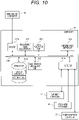
- FIG. 10 is an example of a functional block diagram of a controller constituting a wind power generator in a second embodiment according to another embodiment.
- the present embodiment is different from the first embodiment in that a yaw angle command value and an operation mode for each wind direction are evaluated beforehand by analysis and a database is created so as to reduce the calculation amount in the controller of the wind power generator 2.
- the same components as in the first embodiment are designated by the same reference numerals, and the description overlapping with the first embodiment will be omitted below.
- the controller 31 includes the measurement value acquisition unit 311, the wind direction calculation unit 312, a data acquisition unit 321, a command value output unit 322, the input I/F 317a, the output I/F 317b, and a storage unit 318b, which are connected with each other to be accessible by the internal bus 319.
- the measurement value acquisition unit 311, the wind direction calculation unit 312, the data acquisition unit 321, and the command value output unit 322 are implemented by, for example, processors such as a CPU (Central Processing Unit), not shown, a ROM that stores various programs, a RAM that temporarily stores data in a calculation process, and a storage device such as an external storage device.
- a processor such as a CPU reads and executes various programs stored in the ROM, and stores calculation results, which are the execution results, in the RAM or the external storage device.
- a processor such as a CPU reads and executes various programs stored in the ROM, and stores calculation results, which are the execution results, in the RAM or the external storage device.
- each functional block is illustrated for facilitating the understanding the description.
- the measurement value acquisition unit 311, the wind direction calculation unit 312, the data acquisition unit 321, and the command value output unit 322 may be configured as one calculation unit, or may be configured to integrate desired functional blocks.
- the measurement value acquisition unit 311 acquires wind direction data and wind speed data that have been measured by the wind direction anemometer 32 via the input I/F 317a and the internal bus 319, and performs for example, A/D conversion processing, smoothing processing (noise removal), or normalization processing.
- the storage unit 318b stores at least each control command value for each wind direction and each wind speed.
- the command values that are stored are command values that have been calculated beforehand by analyzing each wind direction and each wind speed, based on the layout of the wind power generator, and include not only yaw angle command values but also pitch angle command values and command values for a power generator in the degraded operation.
- the wind direction calculation unit 312 acquires the wind direction data that has been processed by the measurement value acquisition unit 311 via the internal bus 319, and determines the direction of the wind that flows into the rotational plane of the rotor 24 of itself (the wind power generator 2a located on the windward side).
- the data acquisition unit 321 acquires the operation mode and the control command value from the storage unit 318b, based on the wind direction and the wind speed that have been obtained by the measurement value acquisition unit 311 and the wind direction calculation unit 312.
- the command value output unit 322 outputs the control mode and the command value, which have been acquired by the data acquisition unit 321 from the storage unit 318b, to the yaw angle controller 33, the pitch angle controller 34, and the power generator controller 35 via the output I/F.
- a method for creating a command value for each wind direction and each wind speed stored in the storage unit 318b will be described.
- a model formula formulated as a function of the wind speed and the wind direction or a method for numerically solving the Navier-Stokes equation, which is the governing equation of the wind can be mentioned.
- the former model formula no numerical analysis is necessary, and the calculation is enabled in the controller as described in the first embodiment.
- the method for solving the governing equation has a high calculation load. Hence, it is difficult to conduct the calculation in the controller, but by analyzing with a dedicated computer or the like beforehand and creating a database, more accurate evaluation of the slipstream region is enabled.
- the calculation amount in the controller 31 is reduced by calculating each control command value for each wind direction and each wind speed beforehand from the positional relationship of the wind power generators. At the same time, by evaluating the slipstream region with higher accuracy, a further improvement in the total power generation amount of the entire wind farm can be expected.
- the present embodiment is different from the first and second embodiments in that original yaw control is continued even in the degraded operation mode so that the yaw angle command value for each wind direction changes continuously.
- the same components as those in the first and second embodiments are designated by the same reference numerals, and the description overlapping with the first and second embodiments will be omitted below.
- the controller 31 includes the measurement value acquisition unit 311, the wind direction calculation unit 312, the slipstream region calculation unit 313, the yaw angle calculation unit 314, and the mode determination unit 315, the command value calculation unit 316, the input I/F 317a, the output I/F 317b, and the storage unit 318a, which are connected with each other so as to be accessible by the internal bus 319.
- the measurement value acquisition unit 311, the wind direction calculation unit 312, the slipstream region calculation unit 313, the yaw angle calculation unit 314, the mode determination unit 315, and the command value calculation unit 316 are implemented by, for example, processors such as a CPU (Central Processing Unit), not shown, a ROM that stores various programs, a RAM that temporarily stores data in a calculation process, and a storage device such as an external storage device.
- processors such as a CPU (Central Processing Unit), not shown, a ROM that stores various programs, a RAM that temporarily stores data in a calculation process, and a storage device such as an external storage device.
- a processor such as a CPU reads and executes various programs stored in the ROM, and stores calculation results, which are the execution results, in the R_AM or the external storage device. It should be noted that each functional block is illustrated for facilitating the understanding of the description.
- the measurement value acquisition unit 311, the wind direction calculation unit 312, the slipstream region calculation unit 313, the yaw angle calculation unit 314, the mode determination unit 315, and the command value calculation unit 316 may be configured as one calculation unit, or may be configured to integrate desired functional blocks.
- FIG. 11 is a flowchart showing a processing flow of the controller shown in FIG 8 .
- the measurement value acquisition unit 311 acquires the wind direction data and the wind speed data that have been measured by the wind direction anemometer 32 via the input I/F 317a and the internal bus 319, and performs, for example, A/D conversion processing, smoothing processing (noise removal), normalization processing, or the like. Then, the measurement value acquisition unit 311 transfers the wind direction data that has been subjected to the processing to the wind direction calculation unit 312 via the internal bus 319.
- step S102 the wind direction calculation unit 312 determines the direction of the wind that flows into the rotational plane of the rotor 24 of the wind power generator 2a (itself) located on the windward side, based on the wind direction data that has been processed and transferred by the measurement value acquisition unit 311.
- step S103 the slipstream region calculation unit 313 calculates a wind turbine slipstream region (slipstream region), based on the wind direction that has been determined by the wind direction calculation unit 312, the wind speed data that has been processed by the measurement value acquisition unit 311, the current yaw angle (information of the orientation of the rotational plane of the rotor 24), the shape data of the blade 23, and the rotation speed of the rotor 24 or the pitch angle of the blade 23 that are stored in the storage unit 318a.
- a wind turbine slipstream region slipstream region
- step S104 the mode determination unit 315 accesses the storage unit 318a via the internal bus 319, and determines the presence or absence of the wind power generator 2b or 2c, into which the wind turbine slipstream flows, based on the position information of other wind power generators (2b to 2d) installed in the wind farm 1 that has been read from the storage unit 318a and the wind turbine slipstream region (slipstream region) that has been calculated by the slipstream region calculation unit 313.
- the wind power generator 2a located on the windward side causes the yaw angle controller 33 ( FIG.
- step S105 in a case where the wind power generator 2b or 2c, into which the wind turbine slipstream flows, is present, the processing proceeds to step S105.
- step S105 the yaw angle calculation unit 314 accesses the storage unit 318a via the internal bus 319, and calculates a yaw error of the wind power generator on the windward side so that the wind power generator 2b or 2c located on the leeward side is outside the wind turbine slipstream region generated by the wind power generator 2a located on the windward side, based on the position information of the other wind power generators (2b to 2d) installed in the wind farm 1 that has been read from the storage unit 318a and the wind turbine slipstream region (slipstream region) that has been calculated by the slipstream region calculation unit 313.
- step S106 it is determined whether the yaw error that has been obtained by the yaw angle calculation unit 314 is equal to or greater than a threshold value.
- the mode determination unit 315 determines an operation mode, based on the yaw error that has been obtained by the yaw angle calculation unit 314. As a result of the determination, in a case where the absolute value of the yaw error is equal to or less than the threshold value, the processing proceeds to step S108, and the operation mode shifts to the slipstream control mode. On the other hand, in a case where the absolute value of the yaw error is equal to or greater than the threshold value, the processing proceeds to step S107, and sets the degraded operation mode.
- step S107 the degraded operation mode is set, the command value calculation unit 316 calculates control command values in the degraded operation mode, and outputs the command values for the respective controllers to the yaw angle controller 33, the pitch angle controller 34, and the power generator controller 35 via the output I/F 317b.
- FIG. 12 shows an example of a graph of yaw errors in the present embodiment.
- the yaw error is continuously changed so that the yaw error becomes 0 at a wind direction that matches a relative azimuth of the wind power generator 2b or 2c on the leeward side in the degraded operation mode.
- step S109 the yaw angle command value is calculated so that the yaw error is different for each wind direction, and the yaw angle command value is output.
- step S108 the command value calculation unit 316 outputs, to the yaw angle controller 33 via the output I/F, a command value corresponding to the yaw error of the wind power generator located on the windward side that has been calculated by the yaw angle calculation unit 314, so that the wind power generator 2b or 2c located on the leeward side is outside the slipstream region generated by the wind power generator 2a located on the windward side. Then, the processing ends.
- the driving numbers of yaw of the wind power generator on the windward side can be reduced by continuously changing the yaw error of the wind power generator on the windward side, and the reliability of the wind farm can be improved.
- the present embodiment is characteristic in that pitch control is used as a means for shifting to the degraded operation mode.
- pitch control is used as a means for shifting to the degraded operation mode.
- the same components as those in the first to third embodiments are designated by the same reference numerals, and the following description will be omitted, omitting the description overlapping with the first to third embodiments.
- the blades 23, which are rotatably supported (the pitch angle is changed) with respect to the hub 22, are installed in the wind power generator 2.
- the pitch angle represents the mounting angle of the blades 23 with respect to the hub 22.
- causing the blades 23 to be straightly oriented to the wind and changing the pitch angle so that the energy of the wind can be recovered with high efficiency is referred to as fining, and making the blade parallel to the wind so that the pitch angle is changed to escape the wind is referred to as feather.
- the pitch angle controller 34 adjusts the pitch angle to adjust the amount of energy recovered from the wind, and is capable of changing the operation mode.
- the pitch angle is changed to the feather side from the reference control value in the normal operation mode. Accordingly, the amount of energy recovered by the wind power generator is reduced, and the power generation amount is reduced. Accordingly, the load applied to the wind power generator is also reduced, and the degraded operation mode is set.
- the command value of the pitch angle may be a fixed value or may be changed according to the wind conditions such as the wind speed.
- No is selected in S104 or S106 of FIG. 9 and the normal operation mode or the slipstream control mode is set, by returning the pitch angle command value to the reference control value in the normal operation, the amount of energy recovered by the wind power generator becomes the same as usual.
- the total output of the wind farm can be improved and the transition to the degraded operation mode can also be conducted easily.
- the pitch angle control is used for the transition to the degraded operation mode, the amount of energy recovered from the wind by the wind power generator can be directly controlled. Therefore, the transition to the degraded operation mode can be easily conducted.
- the present embodiment is characteristic in that the torque control of the generator 28 installed in the nacelle of the wind power generator is utilized as a means for shifting to the degraded operation mode.
- the same components as those in the first to fourth embodiments are designated by the same reference numerals, and the following description will be omitted, omitting the description overlapping with the first to the fourth embodiments.
- the energy recovered by the wind power generator is expressed as the product of the rotation speed of the rotor 24 and the torque in the power generator.
- the torque is controlled so that the rotation speed of the rotor 24 causes the blades 23 of the wind power generator to produce the energy in a most efficient manner.
- the torque command value is set to a value different from that in the normal operation.
- the torque command value may take both a larger value and a smaller value than the reference control value in the normal operation.
- a method for reducing the amount of energy to be recovered can be considered.
- the torque control value larger than the reference control value in the normal operation the rotation speed of the rotor can be reduced, the operating efficiency of the wind power generator can be lowered, and the operation mode can also be shifted to the degraded operation mode.
- the command value for the torque control may be a fixed value or may be changed according to the wind conditions such as the wind speed.
- the command value for the torque control may be a fixed value or may be changed according to the wind conditions such as the wind speed.
- the normal operation mode or the slipstream control mode is set, by returning the torque command value to the reference control value in the normal operation, the amount of energy recovered by the wind power generator becomes the same as usual.
- the control response is very quick. Accordingly, the operation mode can be shifted to the degraded operation mode earlier, and an improvement in the power generation amount of the wind farm as a whole can be expected.
Landscapes
- Engineering & Computer Science (AREA)
- Life Sciences & Earth Sciences (AREA)
- Sustainable Development (AREA)
- Sustainable Energy (AREA)
- Chemical & Material Sciences (AREA)
- Combustion & Propulsion (AREA)
- Mechanical Engineering (AREA)
- General Engineering & Computer Science (AREA)
- Wind Motors (AREA)
Claims (7)
- Parc éolien (1) comprenant une pluralité de générateurs éoliens (2), la pluralité de générateurs éoliens (2) incluant chacun :un rotor (24) qui tourne en recevant au moins du vent ;un contrôleur (33) d'angle de lacet qui commande une orientation d'un plan de rotation du rotor (24) ; etun dispositif (31) de commutation de mode qui commute un mode de fonctionnement d'un générateur éolien (2),dans lequel le mode de fonctionnement du générateur éolien (2a) situé sur un côté au vent parmi la pluralité de générateurs éoliens (2) est changé pour chaque direction de vent (53),dans lequel le dispositif (31) de commutation de mode a une unité (315) de détermination de mode qui est adaptée à sélectionner le mode de fonctionnement du générateur éolien (2a) sur le côté au vent parmi trois modes incluant un mode de fonctionnement normal dans lequel l'influence de l'écoulement d'air n'est pas prise en compte et un mode de commande d'écoulement d'air dans lequel l'écoulement d'air ne pénètre pas dans le générateur éolien (2b, 2c) sur le côté sous le vent,caractérisé en ce que l'unité (315) de détermination de mode est adaptée à sélectionner, comme le troisième mode de fonctionnement du générateur éolien (2a) sur le côté au vent, un mode de fonctionnement dégradé dans lequel le fonctionnement du générateur éolien (2a) est dégradé de façon à limiter l'influence de l'écoulement d'air, sur la base d'une information d'erreur de lacet nécessitée par le générateur éolien (2a) sur le côté au vent.
- Parc éolien (1) selon la revendication 1, dans lequel une valeur de commande d'erreur de lacet pour chacune des directions de vent (53) est calculée à partir d'une position relative par rapport à un générateur éolien (2) à proximité, et le mode de fonctionnement du générateur éolien (2a) situé sur le côté au vent parmi la pluralité de générateurs éoliens (2) est changé, sur la base de la valeur de commande d'erreur de lacet.
- Parc éolien (1) selon la revendication 2, dans lequel un azimut relatif et une distance entre la pluralité de générateurs éoliens (2) sont utilisés, comme la position relative du générateur éolien (2a) situé sur le côté au vent parmi la pluralité de générateurs éoliens (2) par rapport au générateur éolien (2) à proximité.
- Parc éolien (1) selon une quelconque revendication précédente, dans lequel un angle de calage du générateur éolien (2a) situé sur le côté au vent parmi la pluralité de générateurs éoliens (2) est commandé comme un moyen pour commuter sur le mode de fonctionnement dégradé.
- Parc éolien (1) selon une quelconque revendication précédente, dans lequel un couple du générateur éolien (2a) situé sur le côté au vent parmi la pluralité de générateurs éoliens (2) est commandé comme un moyen pour commuter sur le mode de fonctionnement dégradé.
- Parc éolien (1) selon une quelconque revendication précédente, dans lequel, dans le mode de fonctionnement dégradé, le générateur éolien (2a) sur le côté au vent change en continu une erreur (55) de lacet, et calcule une valeur de commande d'erreur de lacet pour fixer l'erreur (55) de lacet à 0 à une direction de vent (53) qui correspond à un azimut relatif du générateur éolien (2b, 2c) sur le côté sous le vent.
- Parc éolien (1) selon une quelconque revendication précédente, dans lequel une commande de lacet est utilisée comme un moyen pour commuter parmi les trois modes de fonctionnement.
Applications Claiming Priority (2)
| Application Number | Priority Date | Filing Date | Title |
|---|---|---|---|
| JP2018175578A JP7045294B2 (ja) | 2018-09-20 | 2018-09-20 | ウィンドファーム |
| PCT/JP2019/019860 WO2020059207A1 (fr) | 2018-09-20 | 2019-05-20 | Parc éolien |
Publications (3)
| Publication Number | Publication Date |
|---|---|
| EP3855016A1 EP3855016A1 (fr) | 2021-07-28 |
| EP3855016A4 EP3855016A4 (fr) | 2022-05-25 |
| EP3855016B1 true EP3855016B1 (fr) | 2023-03-01 |
Family
ID=69886801
Family Applications (1)
| Application Number | Title | Priority Date | Filing Date |
|---|---|---|---|
| EP19863808.2A Active EP3855016B1 (fr) | 2018-09-20 | 2019-05-20 | Parc éolien |
Country Status (4)
| Country | Link |
|---|---|
| EP (1) | EP3855016B1 (fr) |
| JP (1) | JP7045294B2 (fr) |
| TW (1) | TWI717000B (fr) |
| WO (1) | WO2020059207A1 (fr) |
Family Cites Families (9)
| Publication number | Priority date | Publication date | Assignee | Title |
|---|---|---|---|---|
| EP2450568B1 (fr) * | 2005-05-31 | 2018-04-18 | Hitachi, Ltd. | Éolienne à axe horizontal |
| DE102007022705A1 (de) | 2007-05-15 | 2008-11-20 | Siemens Ag | Verfahren zum Betrieb eines Windparks mit einer Mehrzahl von Windkraftanlagen |
| WO2012056564A1 (fr) * | 2010-10-29 | 2012-05-03 | 三菱重工業株式会社 | Dispositif de commande destiné à un dispositif générateur d'électricité éolien, parc à éoliennes, et procédé de commande d'un dispositif générateur d'électricité éolien |
| US9201410B2 (en) * | 2011-12-23 | 2015-12-01 | General Electric Company | Methods and systems for optimizing farm-level metrics in a wind farm |
| US9512820B2 (en) * | 2013-02-19 | 2016-12-06 | Siemens Aktiengesellschaft | Method and system for improving wind farm power production efficiency |
| EP3159537A4 (fr) * | 2014-03-14 | 2017-11-15 | Hitachi, Ltd. | Procédé de commande de ferme éolienne et système de commande de ferme éolienne |
| EP3037657A1 (fr) | 2014-12-23 | 2016-06-29 | ABB Technology AG | Fonctionnement optimal de parc éolien |
| JP6869685B2 (ja) | 2016-10-06 | 2021-05-12 | 株式会社日立製作所 | ウィンドファーム及び風力発電装置 |
| JP2018135772A (ja) * | 2017-02-21 | 2018-08-30 | 株式会社日立製作所 | 複数の風力発電装置の制御装置、ウィンドファームまたは複数の風力発電装置の制御方法 |
-
2018
- 2018-09-20 JP JP2018175578A patent/JP7045294B2/ja active Active
-
2019
- 2019-05-20 EP EP19863808.2A patent/EP3855016B1/fr active Active
- 2019-05-20 WO PCT/JP2019/019860 patent/WO2020059207A1/fr unknown
- 2019-09-05 TW TW108132003A patent/TWI717000B/zh active
Also Published As
| Publication number | Publication date |
|---|---|
| JP2020045833A (ja) | 2020-03-26 |
| EP3855016A1 (fr) | 2021-07-28 |
| WO2020059207A1 (fr) | 2020-03-26 |
| JP7045294B2 (ja) | 2022-03-31 |
| EP3855016A4 (fr) | 2022-05-25 |
| TW202012775A (zh) | 2020-04-01 |
| TWI717000B (zh) | 2021-01-21 |
Similar Documents
| Publication | Publication Date | Title |
|---|---|---|
| US9957951B2 (en) | Wind turbine | |
| EP2878811B1 (fr) | Procédé de fonctionnement d'une éolienne et éoliennes | |
| EP2479426B1 (fr) | Procédés et systèmes pour déterminer un signal de décalage d'angle de pas et pour contrôler la fréquence d'un rotor d'une éolienne pour le contrôle d'évitement de la vitesse | |
| US8128362B2 (en) | Method of operating a wind turbine, a wind turbine and a cluster of wind turbines | |
| EP2307715B2 (fr) | Limitation de puissance d'éoliennes | |
| US10364796B2 (en) | Control method for a wind turbine | |
| CN102454544B (zh) | 调整风力涡轮机功率参数的系统和方法 | |
| CN203939626U (zh) | 用于在偏航误差过程中减小风力涡轮机上负载的控制系统 | |
| US9719494B2 (en) | Methods of operating a wind turbine, wind turbines and wind parks | |
| JP6869685B2 (ja) | ウィンドファーム及び風力発電装置 | |
| KR20090083371A (ko) | 풍력 발전 장치, 풍력 발전 시스템 및 풍력 발전 장치의 발전 제어 방법 | |
| WO2009026930A2 (fr) | Procédé de commande d'au moins un mécanisme de réglage d'une éolienne, éolienne et parc éolien | |
| EP3855016B1 (fr) | Parc éolien | |
| CN114876732A (zh) | 一种风电机组变桨的控制方法及装置 | |
| EP3828408A1 (fr) | Procédé et appareil de surveillance d'une éolienne mise en uvre par ordinateur | |
| CN112523947A (zh) | 用于调整风力涡轮的多维操作空间的系统和方法 | |
| EP3394438B1 (fr) | Procédé et système de commande d'éoliennes dans un parc éolien | |
| JP2023165630A (ja) | 風力タービン制御 |
Legal Events
| Date | Code | Title | Description |
|---|---|---|---|
| STAA | Information on the status of an ep patent application or granted ep patent |
Free format text: STATUS: THE INTERNATIONAL PUBLICATION HAS BEEN MADE |
|
| PUAI | Public reference made under article 153(3) epc to a published international application that has entered the european phase |
Free format text: ORIGINAL CODE: 0009012 |
|
| STAA | Information on the status of an ep patent application or granted ep patent |
Free format text: STATUS: REQUEST FOR EXAMINATION WAS MADE |
|
| 17P | Request for examination filed |
Effective date: 20210309 |
|
| AK | Designated contracting states |
Kind code of ref document: A1 Designated state(s): AL AT BE BG CH CY CZ DE DK EE ES FI FR GB GR HR HU IE IS IT LI LT LU LV MC MK MT NL NO PL PT RO RS SE SI SK SM TR |
|
| DAV | Request for validation of the european patent (deleted) | ||
| DAX | Request for extension of the european patent (deleted) | ||
| A4 | Supplementary search report drawn up and despatched |
Effective date: 20220426 |
|
| RIC1 | Information provided on ipc code assigned before grant |
Ipc: F03D 7/02 20060101ALI20220420BHEP Ipc: F03D 7/04 20060101AFI20220420BHEP |
|
| GRAP | Despatch of communication of intention to grant a patent |
Free format text: ORIGINAL CODE: EPIDOSNIGR1 |
|
| STAA | Information on the status of an ep patent application or granted ep patent |
Free format text: STATUS: GRANT OF PATENT IS INTENDED |
|
| RIC1 | Information provided on ipc code assigned before grant |
Ipc: F03D 7/02 20060101ALI20221019BHEP Ipc: F03D 7/04 20060101AFI20221019BHEP |
|
| INTG | Intention to grant announced |
Effective date: 20221123 |
|
| GRAS | Grant fee paid |
Free format text: ORIGINAL CODE: EPIDOSNIGR3 |
|
| GRAA | (expected) grant |
Free format text: ORIGINAL CODE: 0009210 |
|
| STAA | Information on the status of an ep patent application or granted ep patent |
Free format text: STATUS: THE PATENT HAS BEEN GRANTED |
|
| AK | Designated contracting states |
Kind code of ref document: B1 Designated state(s): AL AT BE BG CH CY CZ DE DK EE ES FI FR GB GR HR HU IE IS IT LI LT LU LV MC MK MT NL NO PL PT RO RS SE SI SK SM TR |
|
| REG | Reference to a national code |
Ref country code: GB Ref legal event code: FG4D |
|
| REG | Reference to a national code |
Ref country code: CH Ref legal event code: EP Ref country code: AT Ref legal event code: REF Ref document number: 1551134 Country of ref document: AT Kind code of ref document: T Effective date: 20230315 |
|
| REG | Reference to a national code |
Ref country code: DE Ref legal event code: R096 Ref document number: 602019025994 Country of ref document: DE |
|
| REG | Reference to a national code |
Ref country code: IE Ref legal event code: FG4D |
|
| REG | Reference to a national code |
Ref country code: LT Ref legal event code: MG9D |
|
| REG | Reference to a national code |
Ref country code: NL Ref legal event code: MP Effective date: 20230301 |
|
| PG25 | Lapsed in a contracting state [announced via postgrant information from national office to epo] |
Ref country code: RS Free format text: LAPSE BECAUSE OF FAILURE TO SUBMIT A TRANSLATION OF THE DESCRIPTION OR TO PAY THE FEE WITHIN THE PRESCRIBED TIME-LIMIT Effective date: 20230301 Ref country code: NO Free format text: LAPSE BECAUSE OF FAILURE TO SUBMIT A TRANSLATION OF THE DESCRIPTION OR TO PAY THE FEE WITHIN THE PRESCRIBED TIME-LIMIT Effective date: 20230601 Ref country code: LV Free format text: LAPSE BECAUSE OF FAILURE TO SUBMIT A TRANSLATION OF THE DESCRIPTION OR TO PAY THE FEE WITHIN THE PRESCRIBED TIME-LIMIT Effective date: 20230301 Ref country code: LT Free format text: LAPSE BECAUSE OF FAILURE TO SUBMIT A TRANSLATION OF THE DESCRIPTION OR TO PAY THE FEE WITHIN THE PRESCRIBED TIME-LIMIT Effective date: 20230301 Ref country code: HR Free format text: LAPSE BECAUSE OF FAILURE TO SUBMIT A TRANSLATION OF THE DESCRIPTION OR TO PAY THE FEE WITHIN THE PRESCRIBED TIME-LIMIT Effective date: 20230301 Ref country code: ES Free format text: LAPSE BECAUSE OF FAILURE TO SUBMIT A TRANSLATION OF THE DESCRIPTION OR TO PAY THE FEE WITHIN THE PRESCRIBED TIME-LIMIT Effective date: 20230301 |
|
| PGFP | Annual fee paid to national office [announced via postgrant information from national office to epo] |
Ref country code: DE Payment date: 20230530 Year of fee payment: 5 |
|
| REG | Reference to a national code |
Ref country code: AT Ref legal event code: MK05 Ref document number: 1551134 Country of ref document: AT Kind code of ref document: T Effective date: 20230301 |
|
| PG25 | Lapsed in a contracting state [announced via postgrant information from national office to epo] |
Ref country code: SE Free format text: LAPSE BECAUSE OF FAILURE TO SUBMIT A TRANSLATION OF THE DESCRIPTION OR TO PAY THE FEE WITHIN THE PRESCRIBED TIME-LIMIT Effective date: 20230301 Ref country code: PL Free format text: LAPSE BECAUSE OF FAILURE TO SUBMIT A TRANSLATION OF THE DESCRIPTION OR TO PAY THE FEE WITHIN THE PRESCRIBED TIME-LIMIT Effective date: 20230301 Ref country code: NL Free format text: LAPSE BECAUSE OF FAILURE TO SUBMIT A TRANSLATION OF THE DESCRIPTION OR TO PAY THE FEE WITHIN THE PRESCRIBED TIME-LIMIT Effective date: 20230301 Ref country code: GR Free format text: LAPSE BECAUSE OF FAILURE TO SUBMIT A TRANSLATION OF THE DESCRIPTION OR TO PAY THE FEE WITHIN THE PRESCRIBED TIME-LIMIT Effective date: 20230602 Ref country code: FI Free format text: LAPSE BECAUSE OF FAILURE TO SUBMIT A TRANSLATION OF THE DESCRIPTION OR TO PAY THE FEE WITHIN THE PRESCRIBED TIME-LIMIT Effective date: 20230301 |
|
| PG25 | Lapsed in a contracting state [announced via postgrant information from national office to epo] |
Ref country code: SM Free format text: LAPSE BECAUSE OF FAILURE TO SUBMIT A TRANSLATION OF THE DESCRIPTION OR TO PAY THE FEE WITHIN THE PRESCRIBED TIME-LIMIT Effective date: 20230301 Ref country code: RO Free format text: LAPSE BECAUSE OF FAILURE TO SUBMIT A TRANSLATION OF THE DESCRIPTION OR TO PAY THE FEE WITHIN THE PRESCRIBED TIME-LIMIT Effective date: 20230301 Ref country code: PT Free format text: LAPSE BECAUSE OF FAILURE TO SUBMIT A TRANSLATION OF THE DESCRIPTION OR TO PAY THE FEE WITHIN THE PRESCRIBED TIME-LIMIT Effective date: 20230703 Ref country code: EE Free format text: LAPSE BECAUSE OF FAILURE TO SUBMIT A TRANSLATION OF THE DESCRIPTION OR TO PAY THE FEE WITHIN THE PRESCRIBED TIME-LIMIT Effective date: 20230301 Ref country code: CZ Free format text: LAPSE BECAUSE OF FAILURE TO SUBMIT A TRANSLATION OF THE DESCRIPTION OR TO PAY THE FEE WITHIN THE PRESCRIBED TIME-LIMIT Effective date: 20230301 Ref country code: AT Free format text: LAPSE BECAUSE OF FAILURE TO SUBMIT A TRANSLATION OF THE DESCRIPTION OR TO PAY THE FEE WITHIN THE PRESCRIBED TIME-LIMIT Effective date: 20230301 |
|
| PGFP | Annual fee paid to national office [announced via postgrant information from national office to epo] |
Ref country code: GB Payment date: 20230523 Year of fee payment: 5 |
|
| PG25 | Lapsed in a contracting state [announced via postgrant information from national office to epo] |
Ref country code: SK Free format text: LAPSE BECAUSE OF FAILURE TO SUBMIT A TRANSLATION OF THE DESCRIPTION OR TO PAY THE FEE WITHIN THE PRESCRIBED TIME-LIMIT Effective date: 20230301 Ref country code: IS Free format text: LAPSE BECAUSE OF FAILURE TO SUBMIT A TRANSLATION OF THE DESCRIPTION OR TO PAY THE FEE WITHIN THE PRESCRIBED TIME-LIMIT Effective date: 20230701 |
|
| REG | Reference to a national code |
Ref country code: DE Ref legal event code: R097 Ref document number: 602019025994 Country of ref document: DE |
|
| REG | Reference to a national code |
Ref country code: CH Ref legal event code: PL |
|
| PLBE | No opposition filed within time limit |
Free format text: ORIGINAL CODE: 0009261 |
|
| STAA | Information on the status of an ep patent application or granted ep patent |
Free format text: STATUS: NO OPPOSITION FILED WITHIN TIME LIMIT |
|
| PG25 | Lapsed in a contracting state [announced via postgrant information from national office to epo] |
Ref country code: MC Free format text: LAPSE BECAUSE OF FAILURE TO SUBMIT A TRANSLATION OF THE DESCRIPTION OR TO PAY THE FEE WITHIN THE PRESCRIBED TIME-LIMIT Effective date: 20230301 |
|
| REG | Reference to a national code |
Ref country code: BE Ref legal event code: MM Effective date: 20230531 |
|
| PG25 | Lapsed in a contracting state [announced via postgrant information from national office to epo] |
Ref country code: SI Free format text: LAPSE BECAUSE OF FAILURE TO SUBMIT A TRANSLATION OF THE DESCRIPTION OR TO PAY THE FEE WITHIN THE PRESCRIBED TIME-LIMIT Effective date: 20230301 Ref country code: MC Free format text: LAPSE BECAUSE OF FAILURE TO SUBMIT A TRANSLATION OF THE DESCRIPTION OR TO PAY THE FEE WITHIN THE PRESCRIBED TIME-LIMIT Effective date: 20230301 Ref country code: LU Free format text: LAPSE BECAUSE OF NON-PAYMENT OF DUE FEES Effective date: 20230520 Ref country code: LI Free format text: LAPSE BECAUSE OF NON-PAYMENT OF DUE FEES Effective date: 20230531 Ref country code: DK Free format text: LAPSE BECAUSE OF FAILURE TO SUBMIT A TRANSLATION OF THE DESCRIPTION OR TO PAY THE FEE WITHIN THE PRESCRIBED TIME-LIMIT Effective date: 20230301 Ref country code: CH Free format text: LAPSE BECAUSE OF NON-PAYMENT OF DUE FEES Effective date: 20230531 |
|
| 26N | No opposition filed |
Effective date: 20231204 |
|
| REG | Reference to a national code |
Ref country code: IE Ref legal event code: MM4A |
|
| PG25 | Lapsed in a contracting state [announced via postgrant information from national office to epo] |
Ref country code: IE Free format text: LAPSE BECAUSE OF NON-PAYMENT OF DUE FEES Effective date: 20230520 |
|
| PG25 | Lapsed in a contracting state [announced via postgrant information from national office to epo] |
Ref country code: IE Free format text: LAPSE BECAUSE OF NON-PAYMENT OF DUE FEES Effective date: 20230520 |