EP3854895A1 - Copper electrode material - Google Patents
Copper electrode material Download PDFInfo
- Publication number
- EP3854895A1 EP3854895A1 EP20762902.3A EP20762902A EP3854895A1 EP 3854895 A1 EP3854895 A1 EP 3854895A1 EP 20762902 A EP20762902 A EP 20762902A EP 3854895 A1 EP3854895 A1 EP 3854895A1
- Authority
- EP
- European Patent Office
- Prior art keywords
- less
- mass
- ppm
- content
- sample
- Prior art date
- Legal status (The legal status is an assumption and is not a legal conclusion. Google has not performed a legal analysis and makes no representation as to the accuracy of the status listed.)
- Granted
Links
Images


Classifications
-
- H—ELECTRICITY
- H01—ELECTRIC ELEMENTS
- H01B—CABLES; CONDUCTORS; INSULATORS; SELECTION OF MATERIALS FOR THEIR CONDUCTIVE, INSULATING OR DIELECTRIC PROPERTIES
- H01B1/00—Conductors or conductive bodies characterised by the conductive materials; Selection of materials as conductors
- H01B1/02—Conductors or conductive bodies characterised by the conductive materials; Selection of materials as conductors mainly consisting of metals or alloys
- H01B1/026—Alloys based on copper
-
- H—ELECTRICITY
- H01—ELECTRIC ELEMENTS
- H01S—DEVICES USING THE PROCESS OF LIGHT AMPLIFICATION BY STIMULATED EMISSION OF RADIATION [LASER] TO AMPLIFY OR GENERATE LIGHT; DEVICES USING STIMULATED EMISSION OF ELECTROMAGNETIC RADIATION IN WAVE RANGES OTHER THAN OPTICAL
- H01S3/00—Lasers, i.e. devices using stimulated emission of electromagnetic radiation in the infrared, visible or ultraviolet wave range
- H01S3/02—Constructional details
- H01S3/03—Constructional details of gas laser discharge tubes
- H01S3/038—Electrodes, e.g. special shape, configuration or composition
- H01S3/0388—Compositions, materials or coatings
-
- C—CHEMISTRY; METALLURGY
- C22—METALLURGY; FERROUS OR NON-FERROUS ALLOYS; TREATMENT OF ALLOYS OR NON-FERROUS METALS
- C22C—ALLOYS
- C22C9/00—Alloys based on copper
- C22C9/01—Alloys based on copper with aluminium as the next major constituent
-
- C—CHEMISTRY; METALLURGY
- C22—METALLURGY; FERROUS OR NON-FERROUS ALLOYS; TREATMENT OF ALLOYS OR NON-FERROUS METALS
- C22C—ALLOYS
- C22C9/00—Alloys based on copper
-
- C—CHEMISTRY; METALLURGY
- C22—METALLURGY; FERROUS OR NON-FERROUS ALLOYS; TREATMENT OF ALLOYS OR NON-FERROUS METALS
- C22F—CHANGING THE PHYSICAL STRUCTURE OF NON-FERROUS METALS AND NON-FERROUS ALLOYS
- C22F1/00—Changing the physical structure of non-ferrous metals or alloys by heat treatment or by hot or cold working
- C22F1/08—Changing the physical structure of non-ferrous metals or alloys by heat treatment or by hot or cold working of copper or alloys based thereon
-
- H—ELECTRICITY
- H01—ELECTRIC ELEMENTS
- H01B—CABLES; CONDUCTORS; INSULATORS; SELECTION OF MATERIALS FOR THEIR CONDUCTIVE, INSULATING OR DIELECTRIC PROPERTIES
- H01B1/00—Conductors or conductive bodies characterised by the conductive materials; Selection of materials as conductors
- H01B1/02—Conductors or conductive bodies characterised by the conductive materials; Selection of materials as conductors mainly consisting of metals or alloys
-
- H—ELECTRICITY
- H01—ELECTRIC ELEMENTS
- H01S—DEVICES USING THE PROCESS OF LIGHT AMPLIFICATION BY STIMULATED EMISSION OF RADIATION [LASER] TO AMPLIFY OR GENERATE LIGHT; DEVICES USING STIMULATED EMISSION OF ELECTROMAGNETIC RADIATION IN WAVE RANGES OTHER THAN OPTICAL
- H01S3/00—Lasers, i.e. devices using stimulated emission of electromagnetic radiation in the infrared, visible or ultraviolet wave range
- H01S3/02—Constructional details
- H01S3/03—Constructional details of gas laser discharge tubes
- H01S3/038—Electrodes, e.g. special shape, configuration or composition
-
- H—ELECTRICITY
- H01—ELECTRIC ELEMENTS
- H01S—DEVICES USING THE PROCESS OF LIGHT AMPLIFICATION BY STIMULATED EMISSION OF RADIATION [LASER] TO AMPLIFY OR GENERATE LIGHT; DEVICES USING STIMULATED EMISSION OF ELECTROMAGNETIC RADIATION IN WAVE RANGES OTHER THAN OPTICAL
- H01S3/00—Lasers, i.e. devices using stimulated emission of electromagnetic radiation in the infrared, visible or ultraviolet wave range
- H01S3/14—Lasers, i.e. devices using stimulated emission of electromagnetic radiation in the infrared, visible or ultraviolet wave range characterised by the material used as the active medium
- H01S3/22—Gases
- H01S3/223—Gases the active gas being polyatomic, i.e. containing two or more atoms
- H01S3/225—Gases the active gas being polyatomic, i.e. containing two or more atoms comprising an excimer or exciplex
- H01S3/2251—ArF, i.e. argon fluoride is comprised for lasing around 193 nm
-
- H—ELECTRICITY
- H01—ELECTRIC ELEMENTS
- H01S—DEVICES USING THE PROCESS OF LIGHT AMPLIFICATION BY STIMULATED EMISSION OF RADIATION [LASER] TO AMPLIFY OR GENERATE LIGHT; DEVICES USING STIMULATED EMISSION OF ELECTROMAGNETIC RADIATION IN WAVE RANGES OTHER THAN OPTICAL
- H01S3/00—Lasers, i.e. devices using stimulated emission of electromagnetic radiation in the infrared, visible or ultraviolet wave range
- H01S3/14—Lasers, i.e. devices using stimulated emission of electromagnetic radiation in the infrared, visible or ultraviolet wave range characterised by the material used as the active medium
- H01S3/22—Gases
- H01S3/223—Gases the active gas being polyatomic, i.e. containing two or more atoms
- H01S3/225—Gases the active gas being polyatomic, i.e. containing two or more atoms comprising an excimer or exciplex
- H01S3/2256—KrF, i.e. krypton fluoride is comprised for lasing around 248 nm
Definitions
- the present invention relates to a copper electrode material that can be suitably used for electrodes employed in an acidic atmosphere.
- pulsed laser light has been used for integrated circuit photolithography.
- the pulsed laser light can be generated by applying gas discharge between a pair of electrodes at very short electric discharge and at very high voltage in a gas discharge medium.
- gas discharge between a pair of electrodes at very short electric discharge and at very high voltage in a gas discharge medium.
- fluorine-containing plasma is generated between the pair of electrodes during operation.
- the fluorine-containing plasma is highly corrosive to metals.
- the electrodes corrode over time during operation of a pulsed laser generator.
- the corrosion of the electrodes forms a corrosion spot, which causes arcing in the plasma, thereby further accelerating shortening of the lifetime of the electrode.
- Patent Literature 1 discloses the use of a Cu alloy and an Al alloy as electrode alloys. However, corrosion significantly progress for both of the alloys.
- Patent Literature 2 discloses a technique for prolonging the lifetime of the electrode by using phosphorus-doped brass as a copper alloy used for the electrode to reduce generation of micropores in the brass.
- Patent Literature 3 discloses a technique for producing a main discharge electrode by forming irregularity on a metal and then carrying out electric discharge in a halogen gas to form a film. However, it does not disclose that a corrosion resistance property of the material metal itself is improved.
- Patent Literature 4 discloses a technique for improving a preliminary electrolytic dissociation efficiency by plastic-deforming an auxiliary electrode provided with elasticity to bring the auxiliary electrode into contact with a dielectric tube. However, it does not disclose that a corrosion resistance property of the material metal itself is improved.
- the lifetime of the electrode can be further prolonged if corrosion resistance of a copper-containing electrode material is improved. Further, in the technique for prolonging the lifetime by using phosphorus-doped brass, a burden to an increase in the number of steps is caused due to a step of doping the copper-containing alloy with phosphorus to a target concentration. It is preferable that such a burden can be avoided.
- an object of the present invention is to provide a copper-containing electrode material having improved corrosion resistance.
- the present invention includes the following aspect (1): (1)
- a copper electrode material comprising Cu and inevitable impurities, wherein the inevitable impurities have a content of 1 ppm by mass or less, and an average crystal grain diameter of 100 ⁇ m or less.
- a corrosion-resistant copper electrode material is obtained.
- the copper electrode material according to the present invention can be suitably used for electrodes employed in an acidic atmosphere, and is particularly suitable for electrodes of ArF laser systems and KrF laser systems.
- the copper electrode material according to the present invention does not require any doping of other elements during the production and can be produced while avoiding the burden to an increase in the number of steps involved by those doping steps.
- a copper electrode material according to the present invention includes Cu and inevitable impurities, wherein the inevitable impurities have a content of 1 ppm by mass or less, and an average crystal grain diameter of 100 ⁇ m or less.
- the copper electrode material according to the present invention has improved corrosion resistance in a fluorine-containing environment. Therefore, it can be suitably used as a material for corrosion-resistant copper electrodes.
- the copper electrode material according to the present invention exhibits improved corrosion resistance while avoiding secondary impurity contamination caused by doping for adding other elements, so that it can be used as a high-purity electrode material.
- the copper electrode material according to the present invention can be formed into an electrode having improved corrosion resistance in combination with the technique for improving corrosion resistance by devising an electrode structure, which is a known art.
- the corrosion resistance can be specifically tested by a nitrohydrofluoric acid test as shown in Examples.
- the copper electrode material may have an average crystal grain diameter, for example, in a range of 100 ⁇ m or less, and preferably 75 ⁇ m or less, and more preferably 50 ⁇ m or less, and still more preferably 30 ⁇ m or less, and still more preferably 25 ⁇ m or less, and still more preferably 20 ⁇ m or less.
- the lower limit of the average crystal grain diameter may be, for example, 1 ⁇ m or more, or 5 ⁇ m or more, or 10 ⁇ m or more, although not particularly limited thereto.
- the average crystal grain diameter can be measured and calculated by known means, for example, by means as described below in Examples.
- the content of inevitable impurities can be, for example, 1 ppm by mass or less, and preferably 0.5 ppm by mass or less.
- the copper electrode material according to the present invention can have a Cu content of, for example, 99.9999% by mass or more, and preferably 99.99995% by mass or more.
- the content of each of the following elements as inevitable impurities can be in the range as described.
- the units of the numerical values of the following contents described below are % by mass for those shown as wt%, and ppm by mass for those which are not specifically described.
- the contents of the gas components C and O may be, in total, for example, 5 ppm by mass or less, and preferably 2 ppm by mass or less, as contents of inevitable impurities.
- the copper electrode material according to the present invention may have a number of pores having a pore diameter of 10 ⁇ m or more of less than 1 pore/cm 2 , and preferably less than 0.5 pores/cm 2 , and more preferably 0.1 pores/cm 2 , as observed by an optical microscope.
- the number of pores having a pore diameter of 10 ⁇ m or more per unit area can be measured by the means as described below in Examples.
- the copper electrode material according to the present invention may have a number of particles (LPC) of, for example, 1000 [particles/g] or less, and preferably 500 [particles/g] or less, and more preferably 200 [particles/g] or less, and more preferably 100 [particles/] or less, and even more preferably 50 [particles/g] or less.
- LPC number of particles
- the number of particles per unit mass (LPC) can be measured by the means as described below in Examples.
- the copper electrode material according to the present invention can be produced by a production method as described below in Examples. That is, the copper electrode material can be produced by a method including the steps of: preparing an ingot by melting copper that has been purified to a purity of 6N, i.e., 99.9999% (excluding the gas components) in an induction melting furnace; subjecting the resulting ingot to hot forging under conditions as disclosed in Examples; and machining a forged rod obtained by the hot forging into a shape of the electrode material.
- the hot forging can be carried out, for example, at a temperature in a range of from 600 to 800 °C, and preferably from 650 to 750 °C, such that that a reduction ratio of a cross sectional area of the ingot is from 50 to 80%, and preferably from 60 to 80%.
- preheating may be carried out as desired, for example, by heating to the temperature in the above range for 1 to 15 hours.
- the present invention includes the following aspects (1) to (6):
- Copper purified to a purity of 6N i.e., 99.9999% (excluding gas components) by electrolytic refining was melted in an induction melting furnace to prepare an ingot having a diameter of 135 mm and a length of 600 mm.
- the ingot was cut into half length and subjected to hot forging.
- the hot forging was carried out under the following conditions.
- Forging was carried out by preheating the ingot at a temperature of 800 °C for 3 hours, and carrying out reheating in four steps of: first from ⁇ 135 mm to ⁇ 130 mm and then ⁇ 130 mm ⁇ 80 mm square ⁇ 50 mm square ⁇ ⁇ 41 mm at 850 °C for 10 minutes or more in each step. That is, the hot forging process was conducted by carrying out the reheating at 800 °C for 10 minutes or more every time the forging was performed to draw the ingot in the longitudinal direction so as to reduce the cross-sectional area of the ingot to 60 to 80% of the original cross-sectional area. After carrying out the forging up to ⁇ 41 mm, the ingot was cut at each length of 750 mm to obtain four forged rods. The forged rod of Sample 1 was thus obtained.
- a sample collected from the Sample 1 was polished up to # 2000 with abrasive paper, then subjected to buffing, and observed using an optical microscope (Nikon ECLIPSEMA) in accordance with ASTM E 112-96. As a result, the average crystal grain diameter was 15 ⁇ m.
- the optical microscope photograph of Sample 1 is shown in FIG. 1 .
- Example 1 From the round rod (Sample 1), 5.0 g of cut pieces were collected, dissolved in 200 ml of 36.5% hydrochloric acid solution, to which ultrapure water was then added up to 500 ml to obtain a solution which was sampled. The number of particles having a diameter of 0.2 ⁇ m was measured with a particle counter of KL-11A/KS-65 from RION Co., Ltd. The measurement was carried out five times, and an average value thereof was determined to be the number of particles. The results are shown in Table 1.
- alkali metal elements such as Na and K
- radioactive elements such as U and Th
- transition metal elements the contents of transition metal elements
- light metal elements such as Al, Ca and Mg
- other contents of Si Ti, Zr, Hf, B and Ag
- gas components such as C and O
- Example 2 The remaining 1/2 ingot that was not subjected to hot forging in Example 1 was extruded to produce a cylindrical rod (Sample 2).
- the extrusion process was carried out under the following conditions.
- the extrusion process was carried out using a dice having a diameter of ⁇ 40 mm such that a finished diameter was about ⁇ 41 mm while heating it at 700 °C.
- An extrusion pressure at this time was from 150 to 170 kg/cm 2 .
- the extrudate was cut every 750 mm from the extruder side to obtain four extruded rods each having a diameter of ⁇ 41 mm.
- Example 2 For the cylindrical rod (Sample 2), the average crystal grain diameter was determined in the same procedure as that for Sample 1 of Example 1. The average crystal grain diameter of Sample 2 was 250 ⁇ m. An optical microscope photograph of Sample 2 is shown in FIG. 2 . The number of particles for Sample 2 was measured in the same procedure as that for Sample 1. The results are shown in Table 1.
- a cylindrical rod (Sample 3) having a diameter of 35 mm and a length of 700 mm was prepared from the hot-forged ingot.
- the average crystal grain diameter was determined in the same procedure as that for Sample 1.
- the average crystal grain diameter for Sample 3 was 15 ⁇ m.
- An optical microscope photograph of Sample 3 is shown in FIG. 3 .
- Example 4 The extrusion process was carried out under the same conditions as those for Sample 2 in Comparative Example 1.
- the average crystal grain diameter was determined in the same procedure as that for Sample 1 of Example 1.
- the average crystal grain diameter of Sample 4 was 500 ⁇ m.
- An optical microscope photograph of Sample 4 is shown in FIG. 4 .
- composition analysis was carried out as follows.
- the metal elements were analyzed by GD-MS (VG 9000 available from VG Scientific), and the gas components was analyzed by an oxygen/nitrogen analyzer (Model TCH-600) available from LECO for oxygen (O), nitrogen (N) and hydrogen (H), and analyzed by a carbon/sulfur analyzer (Model CS-444) available from LECO for carbon (C).
- O oxygen
- N nitrogen
- H hydrogen
- C carbon/sulfur analyzer
- Table 2 Table 2-1, Table 2-2 and Table 2-3
- those expressed in wt% means % by mass, and those with no specific description means ppm by mass.
- samples were prepared as described in the procedure of the Production Example as described above, and samples 1 and 2 were made from the same ingot, and samples 3 and 4 were made from the same ingot. Therefore, the samples 1 and 2 and samples 3 and 4 had the same composition, respectively.
- Samples 1 to 4 were observed with an optical microscope (observation conditions: polished to # 2000 with abrasive paper, then buffed; used apparatus: Nikon ECLIPSEMA 200 at magnifications of 100).
- the corrosion resistance test using nitric acid was carried out in the following procedure: 8.4 g of each of Samples 1 to 4 (each size: 10 mm x 10 mm x 10 mm) was prepared.
- An aqueous nitric acid solution was prepared by mixing 80 ml of nitric acid (65%) with 420 ml of pure water.
- Each of Samples 1 to 4 was added to 500 ml of the aqueous nitric acid solution, and measured for weight loss after 10 minutes, 30 minutes and 60 minutes of the addition, with stirring at 25 °C, to calculate a dissolved amount (mg/cm 2 ) at each of the above times.
- the results of the corrosion resistance test using nitric acid are shown in FIG. 5 .
- the symbols a, b, c and d in FIG. 5 corresponds to Sample 1, Sample 2, Sample 3, and Sample 4, respectively.
- the horizontal axis of FIG. 5 is a leaching time (minute), and the vertical axis is a dissolved amount (mg/cm 2 ).
- the corrosion resistance test using nitrohydrofluoric acid was carried out in the following procedure: 8.4 g of each of samples 1 to 4 (each size: 10 mm x 10 mm x 10 mm) was prepared.
- An aqueous nitrohydrofluoric acid solution was prepared by mixing 20 ml of hydrofluoric acid (46%), 60 ml of nitric acid (65%) and 420 ml of pure water.
- Each of Samples 1 to 4 was added to 500 ml of the aqueous nitrohydrofluoric acid solution, and measured for weight loss after 10 minutes, 30 minutes and 60 minutes of the addition, with stirring at 25 °C, to calculate a dissolved amount (mg/cm 2 ) at each of the above times.
- FIG. 6 The results of the corrosion resistance test using the aqueous nitrohydrofluoric acid solution are shown in FIG. 6 .
- the symbols a, b, c and d in FIG. 6 corresponds to Sample 1, Sample 2, Sample 3, and Sample 4, respectively.
- the horizontal axis of FIG. 6 is a leaching time (minute), and the vertical axis is a dissolved amount (mg/cm 2 ).
- the ratio of the dissolved amount of Sample 1 to that of Sample 3 was 1/5.43.
- the ratio of the dissolved amount of Sample 1 to that of Sample 3 was 1/8.17.
- the ratio of the dissolved amount of Sample 1 to that of Sample 2 was 1/2.43.
- the ratio of the dissolved amount of Sample 1 to that of Sample 2 was 1/5.
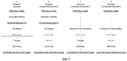
- FIG. 7 shows an explanatory view illustrating the flow of production of Samples 1 to 4 in Example 1 and Comparative Examples 1 to 3.
- the present invention provides a corrosion-resistant copper electrode material.
- the present invention is an industrially useful invention.
Landscapes
- Chemical & Material Sciences (AREA)
- Physics & Mathematics (AREA)
- Engineering & Computer Science (AREA)
- Electromagnetism (AREA)
- Metallurgy (AREA)
- Organic Chemistry (AREA)
- Materials Engineering (AREA)
- Mechanical Engineering (AREA)
- Optics & Photonics (AREA)
- Plasma & Fusion (AREA)
- Thermal Sciences (AREA)
- Crystallography & Structural Chemistry (AREA)
- Manufacture Of Metal Powder And Suspensions Thereof (AREA)
- Manufacture And Refinement Of Metals (AREA)
- Conductive Materials (AREA)
- Battery Electrode And Active Subsutance (AREA)
Abstract
Description
- The present invention relates to a copper electrode material that can be suitably used for electrodes employed in an acidic atmosphere.
- Recently, pulsed laser light has been used for integrated circuit photolithography. The pulsed laser light can be generated by applying gas discharge between a pair of electrodes at very short electric discharge and at very high voltage in a gas discharge medium. For example, in ArF laser systems, fluorine-containing plasma is generated between the pair of electrodes during operation. The fluorine-containing plasma is highly corrosive to metals. As a result, the electrodes corrode over time during operation of a pulsed laser generator. The corrosion of the electrodes forms a corrosion spot, which causes arcing in the plasma, thereby further accelerating shortening of the lifetime of the electrode.
-
Patent Literature 1 discloses the use of a Cu alloy and an Al alloy as electrode alloys. However, corrosion significantly progress for both of the alloys.Patent Literature 2 discloses a technique for prolonging the lifetime of the electrode by using phosphorus-doped brass as a copper alloy used for the electrode to reduce generation of micropores in the brass.Patent Literature 3 discloses a technique for producing a main discharge electrode by forming irregularity on a metal and then carrying out electric discharge in a halogen gas to form a film. However, it does not disclose that a corrosion resistance property of the material metal itself is improved.Patent Literature 4 discloses a technique for improving a preliminary electrolytic dissociation efficiency by plastic-deforming an auxiliary electrode provided with elasticity to bring the auxiliary electrode into contact with a dielectric tube. However, it does not disclose that a corrosion resistance property of the material metal itself is improved. -
- [Patent Literature 1]
Japanese Patent No. 3875451 B - [Patent Literature 2]
Japanese Patent No. 6175496 B - [Patent Literature 3]
Japanese Patent Application Publication No. 2004-146579 A - [Patent Literature 4]
Japanese Patent Application Publication No. H10-242553 A - Even in the prior arts attempting to prolong the lifetime of the electrode by improving the structure of the electrode, the lifetime of the electrode can be further prolonged if corrosion resistance of a copper-containing electrode material is improved. Further, in the technique for prolonging the lifetime by using phosphorus-doped brass, a burden to an increase in the number of steps is caused due to a step of doping the copper-containing alloy with phosphorus to a target concentration. It is preferable that such a burden can be avoided.
- Thus, an object of the present invention is to provide a copper-containing electrode material having improved corrosion resistance.
- As a result of intensive studies, the present inventors have found that a copper electrode material as described below exerts improved corrosion resistance, and they have arrived at the present invention.
- Thus, the present invention includes the following aspect (1): (1)
- A copper electrode material, the copper electrode material comprising Cu and inevitable impurities, wherein the inevitable impurities have a content of 1 ppm by mass or less, and an average crystal grain diameter of 100 µm or less.
- According to the present invention, a corrosion-resistant copper electrode material is obtained. The copper electrode material according to the present invention can be suitably used for electrodes employed in an acidic atmosphere, and is particularly suitable for electrodes of ArF laser systems and KrF laser systems. The copper electrode material according to the present invention does not require any doping of other elements during the production and can be produced while avoiding the burden to an increase in the number of steps involved by those doping steps.
-
-
FIG. 1 is an optical microscope photograph of Sample 1 (Example 1); -
FIG. 2 is an optical microscope photograph of Sample 2 (Comparative Example 1); -
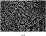
FIG. 3 is an optical microscope photograph of Sample 3 (Comparative Example 2); -
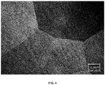
FIG. 4 is an optical microscope photograph of Sample 4 (Comparative Example 3); -
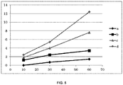
FIG. 5 is a graph showing results of a corrosion resistance test using an aqueous nitric acid solution; -
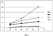
FIG. 6 is a graph showing results of a corrosion resistance test using an aqueous nitrohydrofluoric acid solution; and -
FIG. 7 is an explanatory view illustrating the flow of production ofSamples 1 to 4 in Example 1 and Comparative Examples 1 to 3. - Hereinafter, the present invention will be described in detail by way of embodiments. The present invention is not limited to the specific embodiments as described below.
- A copper electrode material according to the present invention includes Cu and inevitable impurities, wherein the inevitable impurities have a content of 1 ppm by mass or less, and an average crystal grain diameter of 100 µm or less.
- The copper electrode material according to the present invention has improved corrosion resistance in a fluorine-containing environment. Therefore, it can be suitably used as a material for corrosion-resistant copper electrodes. The copper electrode material according to the present invention exhibits improved corrosion resistance while avoiding secondary impurity contamination caused by doping for adding other elements, so that it can be used as a high-purity electrode material. Further, the copper electrode material according to the present invention can be formed into an electrode having improved corrosion resistance in combination with the technique for improving corrosion resistance by devising an electrode structure, which is a known art. The corrosion resistance can be specifically tested by a nitrohydrofluoric acid test as shown in Examples.
- In a preferred embodiment, the copper electrode material may have an average crystal grain diameter, for example, in a range of 100 µm or less, and preferably 75 µm or less, and more preferably 50 µm or less, and still more preferably 30 µm or less, and still more preferably 25 µm or less, and still more preferably 20 µm or less. The lower limit of the average crystal grain diameter may be, for example, 1 µm or more, or 5 µm or more, or 10 µm or more, although not particularly limited thereto. The average crystal grain diameter can be measured and calculated by known means, for example, by means as described below in Examples.
- In the copper electrode material according to the present invention, the content of inevitable impurities can be, for example, 1 ppm by mass or less, and preferably 0.5 ppm by mass or less. In other words, the copper electrode material according to the present invention can have a Cu content of, for example, 99.9999% by mass or more, and preferably 99.99995% by mass or more.
- In a preferred embodiment, the content of each of the following elements as inevitable impurities can be in the range as described. However, the units of the numerical values of the following contents described below are % by mass for those shown as wt%, and ppm by mass for those which are not specifically described.
- Li content: 0.01 ppm by mass or less, and preferably less than 0.001 ppm by mass (less than the measurement limit);
- Be content: 0.01 ppm by mass or less, and preferably less than 0.001 ppm by mass (less than the measurement limit);
- B content: 0.01 ppm by mass or less, and preferably less than 0.001 ppm by mass (less than the measurement limit);
- F content: 0.05 ppm by mass or less, and preferably less than 0.005 ppm by mass (less than the measurement limit);
- Na content: 0.05 ppm by mass or less, and preferably less than 0.005 ppm by mass (less than the measurement limit);
- Mg content: 0.01 ppm by mass or less, and preferably less than 0.001 ppm by mass (less than the measurement limit);
- Al content: 0.1 ppm by mass or less, and preferably 0.05 ppm by mass or less, and more preferably 0.002 ppm by mass or less;
- Si content: 0.05 ppm by mass or less, and preferably 0.024 ppm by mass or less;
- P content: 0.1 ppm by mass or less, and preferably less than 0.05 ppm by mass, and more preferably 0.001 ppm by mass or less, and still more preferably less than 0.001 ppm by mass (less than the measurement limit);
- S content: 0.1 ppm by mass or less, and preferably less than 0.05 ppm by mass, and more preferably 0.01 ppm by mass or less, and further preferably 0.009 ppm by mass or less;
- Cl content: 0.2 ppm by mass or less, and preferably 0.02 ppm by mass or less;
- K content: 0.1 ppm by mass or less, and preferably less than 0.01 ppm by mass (less than the measurement limit);
- Ca content: 0.05 ppm by mass or less, and preferably less than 0.005 ppm by mass (less than the measurement limit);
- Sc content: 0.01 ppm by mass or less, and preferably less than 0.001 ppm by mass (less than the measurement limit);
- Ti content: 0.01 ppm by mass or less, and preferably 0.008 ppm by mass or less;
- V content: 0.01 ppm by mass or less, and preferably less than 0.001 ppm by mass (less than the measurement limit);
- Cr content: 0.01 ppm by mass or less, and preferably less than 0.002 ppm by mass (less than the measurement limit);
- Mn content: 0.01 ppm by mass or less, and preferably less than 0.001 ppm by mass (less than the measurement limit);
- Fe content: 0.1 ppm by mass or less, and preferably less than 0.1 ppm by mass, and more preferably 0.01 ppm by mass or less, and further preferably 0.003 ppm by mass or less;
- Co content: less than 0.05 ppm by mass, and preferably 0.01 ppm by mass or less, and more preferably less than 0.001 ppm by mass (less than the measurement limit);
- Ni content: less than 0.1 ppm by mass, and preferably 0.01 ppm by mass or less, and more preferably less than 0.001 ppm by mass (less than the measurement limit);
- Cu content: -;
- Zn content: 0.05 ppm by mass or less, and preferably less than 0.005 ppm by mass (less than the measurement limit);
- Ga content: 0.1 ppm by mass or less, and preferably less than 0.01 ppm by mass (less than the measurement limit);
- Ge content: 0.05 ppm by mass or less, and preferably less than 0.005 ppm by mass (less than the measurement limit);
- As content: 0.05 ppm by mass or less, and preferably less than 0.005 ppm by mass (less than the measurement limit);
- Se content: 0.1 ppm by mass or less, and preferably less than 0.01 ppm by mass (less than the measurement limit);
- Br content: 0.5 ppm by mass or less, and preferably less than 0.05 ppm by mass (less than the measurement limit);
- Rb content: 0.01 ppm by mass or less, and preferably less than 0.001 ppm by mass (less than the measurement limit);
- Sr content: 0.01 ppm by mass or less, and preferably less than 0.001 ppm by mass (less than the measurement limit);
- Y content: 0.01 ppm by mass or less, and preferably less than 0.001 ppm by mass (less than the measurement limit);
- Zr content: 0.01 ppm by mass or less, and preferably less than 0.001 ppm by mass (less than the measurement limit);
- Nb content: 0.01 ppm by mass or less, and preferably less than 0.001 ppm by mass (less than the measurement limit);
- Mo content: 0.05 ppm by mass or less, and preferably less than 0.005 ppm by mass (less than the measurement limit);
- Ru content: 0.5 ppm by mass or less, and preferably less than 0.05 ppm by mass (less than the measurement limit);
- Rh content: less than 1 ppm by mass, and preferably 0.5 ppm by mass or less, and more preferably less than 0.05 ppm by mass (less than the measurement limit);
- Pd content: 0.05 ppm by mass or less, and preferably less than 0.005 ppm by mass (less than the measurement limit);
- Ag content: less than 1 ppm by mass, and preferably 0.5 ppm by mass or less, and more preferably 0.16 ppm by mass or less;
- Cd content: 0.1 ppm by mass or less, and preferably less than 0.01 ppm by mass (less than the measurement limit);
- In content: 0.05 ppm by mass or less, and preferably less than 0.005 ppm by mass (less than the measurement limit);
- Sn content: less than 0.5 ppm by mass, and preferably 0.1 ppm by mass or less, and more preferably less than 0.01 ppm by mass (less than the measurement limit);
- Sb content: less than 0.005 ppm by mass, and preferably 0.004 ppm by mass or less, and more preferably less than 0.002 ppm by mass (less than the measurement limit);
- Te content: 0.5 ppm by mass or less, and preferably less than 0.05 ppm by mass (less than the measurement limit);
- I content: 0.05 ppm by mass or less, and preferably less than 0.005 ppm by mass (less than the measurement limit);
- Cs content: 0.05 ppm by mass or less, and preferably less than 0.005 ppm by mass (less than the measurement limit);
- Ba content: 0.01 ppm by mass or less, and preferably less than 0.001 ppm by mass (less than the measurement limit);
- La content: 0.01 ppm by mass or less, and preferably less than 0.001 ppm by mass (less than the measurement limit);
- Ce content: 0.01 ppm by mass or less, and preferably less than 0.001 ppm by mass (less than the measurement limit);
- Pr content: 0.01 ppm by mass or less, and preferably less than 0.001 ppm by mass (less than the measurement limit);
- Nd content: 0.01 ppm by mass or less, and preferably less than 0.001 ppm by mass (less than the measurement limit);
- Sm content: 0.01 ppm by mass or less, and preferably less than 0.001 ppm by mass (less than the measurement limit);
- Eu content: 0.01 ppm by mass or less, and preferably less than 0.001 ppm by mass (less than the measurement limit);
- Gd content: 0.01 ppm by mass or less, and preferably less than 0.001 ppm by mass (less than the measurement limit);
- Tb content: 0.01 ppm by mass or less, and preferably less than 0.001 ppm by mass (less than the measurement limit);
- Dy content: 0.01 ppm by mass or less, and preferably less than 0.001 ppm by mass (less than the measurement limit);
- Ho content: 0.01 ppm by mass or less, and preferably less than 0.001 ppm by mass (less than the measurement limit);
- Er content: 0.01 ppm by mass or less, and preferably less than 0.001 ppm by mass (less than the measurement limit);
- Tm content: 0.01 ppm by mass or less, and preferably less than 0.001 ppm by mass (less than the measurement limit);
- Yb content: 0.01 ppm by mass or less, and preferably less than 0.001 ppm by mass (less than the measurement limit);
- Lu content: 0.01 ppm by mass or less, and preferably less than 0.001 ppm by mass (less than the measurement limit);
- Hf content: 0.01 ppm by mass or less, and preferably less than 0.001 ppm by mass (less than the measurement limit);
- Ta content: 10 ppm by mass or less, and preferably less than 5 ppm by mass (less than the measurement limit);
- W content: 0.01 ppm by mass or less, and preferably less than 0.001 ppm by mass (less than the measurement limit);
- Re content: 0.01 ppm by mass or less, and preferably less than 0.001 ppm by mass (less than the measurement limit);
- Os content: 0.01 ppm by mass or less, and preferably less than 0.001 ppm by mass (less than the measurement limit);
- Ir content: 0.01 ppm by mass or less, and preferably less than 0.001 ppm by mass (less than the measurement limit);
- Pt content: 0.1 ppm by mass or less, and preferably less than 0.01 ppm by mass (less than the measurement limit);
- Au content: 0.1 ppm by mass or less, and preferably less than 0.01 ppm by mass (less than the measurement limit);
- Hg content: 0.1 ppm by mass or less, and preferably less than 0.01 ppm by mass (less than the measurement limit);
- Tl content: less than 3 ppm by mass, and preferably 0.5 ppm by mass or less, and more preferably less than 0.001 ppm by mass (less than the measurement limit);
- Pb content: less than 0.05 ppm by mass, and preferably 0.005 ppm by mass or less, and more preferably less than 0.002 ppm by mass (less than the measurement limit);
- Bi content: 0.01 ppm by mass or less, and preferably less than 0.001 ppm by mass (less than the measurement limit);
- Th content: 0.001 ppm by mass or less, and preferably less than 0.0001 ppm by mass (less than the measurement limit);
- U content: 0.001 ppm by mass or less, and preferably less than 0.0001 ppm by mass (less than the measurement limit);
- H content: 2 ppm by mass or less, and preferably less than 1 ppm by mass (less than the measurement limit);
- C content: 2 ppm by mass or less, and preferably less than 1 ppm by mass (less than the measurement limit);
- N content: 2 ppm by mass or less, and preferably less than 1 ppm by mass (less than the measurement limit);
- O content: 2 ppm by mass or less, and preferably less than 1 ppm by mass (less than the measurement limit).
- In a preferred embodiment, the contents of the gas components C and O may be, in total, for example, 5 ppm by mass or less, and preferably 2 ppm by mass or less, as contents of inevitable impurities.
- In a preferred embodiment, the copper electrode material according to the present invention may have a number of pores having a pore diameter of 10 µm or more of less than 1 pore/cm2, and preferably less than 0.5 pores/cm2, and more preferably 0.1 pores/cm2, as observed by an optical microscope. The number of pores having a pore diameter of 10 µm or more per unit area can be measured by the means as described below in Examples.
- In a preferred embodiment, the copper electrode material according to the present invention may have a number of particles (LPC) of, for example, 1000 [particles/g] or less, and preferably 500 [particles/g] or less, and more preferably 200 [particles/g] or less, and more preferably 100 [particles/] or less, and even more preferably 50 [particles/g] or less. The number of particles per unit mass (LPC) can be measured by the means as described below in Examples.
- The copper electrode material according to the present invention can be produced by a production method as described below in Examples. That is, the copper electrode material can be produced by a method including the steps of: preparing an ingot by melting copper that has been purified to a purity of 6N, i.e., 99.9999% (excluding the gas components) in an induction melting furnace; subjecting the resulting ingot to hot forging under conditions as disclosed in Examples; and machining a forged rod obtained by the hot forging into a shape of the electrode material.
- In a preferred embodiment, the hot forging can be carried out, for example, at a temperature in a range of from 600 to 800 °C, and preferably from 650 to 750 °C, such that that a reduction ratio of a cross sectional area of the ingot is from 50 to 80%, and preferably from 60 to 80%. In the hot forging, preheating may be carried out as desired, for example, by heating to the temperature in the above range for 1 to 15 hours.
- As preferable embodiments, the present invention includes the following aspects (1) to (6):
- (1) A copper electrode material, the copper electrode material comprising Cu and inevitable impurities, wherein the inevitable impurities have a content of 1 ppm by mass or less, and an average crystal grain diameter of 100 µm or less.
- (2) The copper electrode material according to (1), wherein the copper electrode has a S content of 0.1 ppm by mass or less, a P content of 0.1 ppm by mass or less, a Fe content of 0.1 ppm by mass or less, and an Al content of 0.1 ppm by mass or less, as contents of the inevitable impurities.
- (3) The copper electrode material according to (1) or (2), wherein the copper electrode material contains gas components C and O in a total amount of 5 ppm by mass or less as contents of the inevitable impurities.
- (4) The copper electrode material according to any one of (1) to (3), wherein the copper electrode material has a number of pores having a pore diameter of 10 µm or more of less than 1 pore/cm2 as observed by an optical microscope.
- (5) The copper electrode material according to any one of (1) to (4), wherein the copper electrode material has a number of particles (LPC) of 1000 [pieces/g] or less.
- (6) The copper electrode material according to any one of (1) to (4), wherein the copper electrode material has a S content of less than 0.05 ppm by mass, a Fe content of less than 0.1 ppm by mass, a Co content of less than 0.05 ppm by mass, a Ni content of less than 0.1 ppm by mass, an As content of less than 0.005 ppm by mass, a Rh content of less than 1 ppm by mass, a Ag content of less than 1 ppm by mass, a Sn content of less than 0.5 ppm by mass, an Sb content of less than 0.005 ppm by mass, a Te content of less than 0.05 ppm by mass, a Tl content of less than 3 ppm by mass, a Pb content of less than 0.05 ppm by mass, and a P content of less than 0.05 ppm by mass.
- Hereinafter, the present invention will be described with reference to Examples. The present invention is not limited to the following Examples. Other examples and variations within the spirit of the present invention are included in the present invention.
- Copper purified to a purity of 6N i.e., 99.9999% (excluding gas components) by electrolytic refining was melted in an induction melting furnace to prepare an ingot having a diameter of 135 mm and a length of 600 mm.
- The ingot was cut into half length and subjected to hot forging. The hot forging was carried out under the following conditions.
- Forging was carried out by preheating the ingot at a temperature of 800 °C for 3 hours, and carrying out reheating in four steps of: first from ϕ 135 mm to ϕ 130 mm and then ϕ 130 mm → 80 mm square → 50 mm square → ϕ 41 mm at 850 °C for 10 minutes or more in each step. That is, the hot forging process was conducted by carrying out the reheating at 800 °C for 10 minutes or more every time the forging was performed to draw the ingot in the longitudinal direction so as to reduce the cross-sectional area of the ingot to 60 to 80% of the original cross-sectional area. After carrying out the forging up to ϕ 41 mm, the ingot was cut at each length of 750 mm to obtain four forged rods. The forged rod of
Sample 1 was thus obtained. - A sample collected from the
Sample 1 was polished up to # 2000 with abrasive paper, then subjected to buffing, and observed using an optical microscope (Nikon ECLIPSEMA) in accordance with ASTM E 112-96. As a result, the average crystal grain diameter was 15 µm. The optical microscope photograph ofSample 1 is shown inFIG. 1 . - From the round rod (Sample 1), 5.0 g of cut pieces were collected, dissolved in 200 ml of 36.5% hydrochloric acid solution, to which ultrapure water was then added up to 500 ml to obtain a solution which was sampled. The number of particles having a diameter of 0.2 µm was measured with a particle counter of KL-11A/KS-65 from RION Co., Ltd. The measurement was carried out five times, and an average value thereof was determined to be the number of particles. The results are shown in Table 1.
- Further, in this case, the contents of alkali metal elements such as Na and K, the contents of radioactive elements such as U and Th, the contents of transition metal elements, the contents of light metal elements such as Al, Ca and Mg, and other contents of Si, Ti, Zr, Hf, B and Ag, and the contents of gas components such as C and O were measured by means as described later. The results are shown in Table 2 (Table 2-1 and Table 2-2, Table 2-3).
[Table 1] Example 1 Comparative Example 1 Comparative Example 2 Comparative Example 3 Sample 1Sample 2Sample 3Sample 4Purity 6N 6N 4N (OFC) 4N (OFC) Average Crystal Grain Diameter (µm) 15 µm 250 µm 15 µm 500 µm LPC (particle/g) 50 50 2000 2000 Number of Pores (pore/cm2) ≈ 0 10 100 1000 Symbols in Corrosion Resistance Graph a b c d - The remaining 1/2 ingot that was not subjected to hot forging in Example 1 was extruded to produce a cylindrical rod (Sample 2). The extrusion process was carried out under the following conditions.
- The extrusion process was carried out using a dice having a diameter of ϕ40 mm such that a finished diameter was about ϕ41 mm while heating it at 700 °C.
An extrusion pressure at this time was from 150 to 170 kg/cm2. The extrudate was cut every 750 mm from the extruder side to obtain four extruded rods each having a diameter of ϕ41 mm. - For the cylindrical rod (Sample 2), the average crystal grain diameter was determined in the same procedure as that for
Sample 1 of Example 1. The average crystal grain diameter ofSample 2 was 250 µm. An optical microscope photograph ofSample 2 is shown inFIG. 2 . The number of particles forSample 2 was measured in the same procedure as that forSample 1. The results are shown in Table 1. - An ingot having a diameter of 135 mm and a length of 600 mm, which was commercially available oxygen-free copper (JX Nippon Mining & Metals Corporation) (
purity 4N), was cut in half in the length direction and subjected to hot forging under the same conditions as those forSample 1 of Example 1. - A cylindrical rod (Sample 3) having a diameter of 35 mm and a length of 700 mm was prepared from the hot-forged ingot.
- For the cylindrical rod (Sample 3), the average crystal grain diameter was determined in the same procedure as that for
Sample 1. The average crystal grain diameter forSample 3 was 15 µm. An optical microscope photograph ofSample 3 is shown inFIG. 3 . - Sampling was performed from the cylindrical rod of
Sample 3 in the same procedure as that forSample 1, and the number of particles having a diameter of 0.2 µm or more was measured with a particle counter. The results are shown in Table 1. - The remaining 1/2 ingot that was not subjected to hot forging in Comparative Example 2 was extruded to produce a cylindrical rod (Sample 4). The extrusion process was carried out under the same conditions as those for
Sample 2 in Comparative Example 1. - For the cylindrical rod (Sample 4), the average crystal grain diameter was determined in the same procedure as that for
Sample 1 of Example 1. The average crystal grain diameter ofSample 4 was 500 µm. An optical microscope photograph ofSample 4 is shown inFIG. 4 . - Sampling was performed from the cylindrical rod of
Sample 4 in the same procedure as that forSample 1, and the number of particles having a diameter of 0.2 µm or more was measured with a particle counter. The results are shown in Table 1. - Specifically, the composition analysis was carried out as follows. For the compositions of
Samples 1 to 4, the metal elements were analyzed by GD-MS (VG 9000 available from VG Scientific), and the gas components was analyzed by an oxygen/nitrogen analyzer (Model TCH-600) available from LECO for oxygen (O), nitrogen (N) and hydrogen (H), and analyzed by a carbon/sulfur analyzer (Model CS-444) available from LECO for carbon (C). The results obtained are shown in Table 2 (Table 2-1, Table 2-2 and Table 2-3) as described below. For units in the table, those expressed in wt% means % by mass, and those with no specific description means ppm by mass. It should be noted that samples were prepared as described in the procedure of the Production Example as described above, andsamples samples samples samples -
[Table 2] 6N- Cu 4N- Cu Sample 1 Sample 3Li <0.001 <0.001 Be <0.001 <0.001 B <0.001 <0.001 F <0.005 <0.005 Na <0.005 <0.005 Mg <0.001 0.003 Al 0.002 0. 064 Si 0.024 0. 19 P <0.001 0.85 S 0.009 4. 3 C1 0.02 0.02 K <0.01 <0.01 Ca <0.005 <0.005 Sc <0.001 <0.001 Ti 0.008 <0.001 V <0.001 0.11 Cr <0.002 0. 16 Mn <0.001 0.021 Fe 0.003 1. 1 Co <0.001 <0.001 Ni <0.001 0. 28 Cu - - Zn <0.005 0.036 Ga <0.01 <0.01 Ge <0.005 <0.005 -
[Table 2 continued] 6N- Cu 4N- Cu Sample 1 Sample 3As <0.005 0.029 Se <0. 01 0. 10 Br <0.05 <0. 05 Rb <0.001 <0.001 Sr <0.001 <0.001 Y <0.001 <0. 001 Zr <0.001 <0.001 Nb <0.001 <0.001 Mo <0.005 0.011 Ru <0.05 <0.05 Rh <0.05 <0. 05 Pd <0.005 <0.005 Ag 0.16 10 Cd <0.01 <0. 01 In <0.005 <0.005 Sn <0.01 0. 05 Sb <0.002 0.11 Te <0. 05 <0.05 I <0.005 <0.005 Cs <0.005 <0.005 Ba <0.001 <0.001 La <0.001 <0.001 Ce <0.001 <0.001 Pr <0.001 <0.001 Nd <0.001 <0.001 Sm <0.001 <0.001 Eu <0.001 <0.001 -
[Table 2 continued] 6N- Cu 4N- Cu Sample 1 Sample 3Gd <0.001 <0.001 Tb <0.001 <0.001 Dy <0.001 <0.001 Ho <0.001 <0. 001 Er <0.001 <0. 001 Tm <0.001 <0.001 Yb <0.001 <0. 001 Lu <0.001 <0.001 Hf <0. 001 <0.001 Ta <5 <5 w <0.001 <0.001 Re <0. 001 <0.001 Os <0.001 <0.001 Ir <0.001 <0.001 Pt <0.01 <0. 01 Au <0.01 <0.01 Hg <0.01 <0. 01 T1 <0.001 <0. 001 Pb <0. 002 0.050 Bi <0.001 0.031 Th <0.0001 <0.0001 U <0.0001 <0.0001 H <1 <1 C <1 2 N <1 <1 0 <1 3 -
Samples 1 to 4 were observed with an optical microscope (observation conditions: polished to # 2000 with abrasive paper, then buffed; used apparatus: Nikon ECLIPSEMA 200 at magnifications of 100). - After polishing each of
Samples 1 to 4, they were observed in a dark field image at magnifications of 100 with an optical microscope. Because of the dark field image, if pores having sizes more than or equal to a certain level is present, those parts are detected as white shining spots. By this method, pores having a maximum length of about 10 µm or more on a polished surface could be detected. By this method, the number of pores per a surface having 10 mm x 10 mm was counted at 10 points, and an average value thereof was calculated. The results are shown in Table 1. -
- In
Sample 1, the number of pores per 10 mm x 10 mm was almost zero. - In
Sample 2, the number of pores per 10 mm x 10 mm was 10. - In
Sample 3, the number of pores per 10 mm x 10 mm was 100. - In
Sample 4, the number of pores per 10 mm x 10 mm was 1000. Further, inSample 4, the presence of larger pores having a pore diameter of 50 µm or more was observed. - As described above, no pore was observed in
Sample 1 when observed with the optical microscope. Further,Sample 2 had very few pores when observed with the optical microscope. On the other hand,Sample 3 had a very large number of pores. Further, the number of pores inSample 4 was smaller than that inSample 3, but it was very larger than that inSample 2, and the presence of larger pores was also observed. - The tensile strength of each of
Samples 1 to 4 was measured based on JIS: Z 2241 (2011). The results are summarized in Table 3. - The conductivity of each of
Samples 1 to 4 was measured using AutoSigma 3000 from GE Sensing & Inspection Technologies Co., Ltd. The results are summarized in Table 3.[Table 3] Sample 1Sample 2Sample 3Sample 4Tensile strength (N/mm2) 324 235 334 278 Conductivity (% lACS) 102 113 86 101 - The corrosion resistance test using nitric acid was carried out in the following procedure:
8.4 g of each ofSamples 1 to 4 (each size: 10 mm x 10 mm x 10 mm) was prepared. An aqueous nitric acid solution was prepared by mixing 80 ml of nitric acid (65%) with 420 ml of pure water. Each ofSamples 1 to 4 was added to 500 ml of the aqueous nitric acid solution, and measured for weight loss after 10 minutes, 30 minutes and 60 minutes of the addition, with stirring at 25 °C, to calculate a dissolved amount (mg/cm2) at each of the above times. The results of the corrosion resistance test using nitric acid are shown inFIG. 5 . The symbols a, b, c and d inFIG. 5 corresponds to Sample 1,Sample 2,Sample 3, andSample 4, respectively. The horizontal axis ofFIG. 5 is a leaching time (minute), and the vertical axis is a dissolved amount (mg/cm2). - The corrosion resistance test using nitrohydrofluoric acid was carried out in the following procedure:
8.4 g of each ofsamples 1 to 4 (each size: 10 mm x 10 mm x 10 mm) was prepared. An aqueous nitrohydrofluoric acid solution was prepared by mixing 20 ml of hydrofluoric acid (46%), 60 ml of nitric acid (65%) and 420 ml of pure water. Each ofSamples 1 to 4 was added to 500 ml of the aqueous nitrohydrofluoric acid solution, and measured for weight loss after 10 minutes, 30 minutes and 60 minutes of the addition, with stirring at 25 °C, to calculate a dissolved amount (mg/cm2) at each of the above times. The results of the corrosion resistance test using the aqueous nitrohydrofluoric acid solution are shown inFIG. 6 . The symbols a, b, c and d inFIG. 6 corresponds to Sample 1,Sample 2,Sample 3, andSample 4, respectively. The horizontal axis ofFIG. 6 is a leaching time (minute), and the vertical axis is a dissolved amount (mg/cm2). - As shown in
FIGS. 5 and6 , inSample 3 andSample 4 each having the larger number of pores, the dissolution rapidly progressed in both the nitric acid test and the nitrohydrofluoric acid test in the same manner. InSample 2 having the decreased number of pores as compared withSamples - For example, after 60 minutes of the nitric acid test, the ratio of the dissolved amount of
Sample 1 to that ofSample 3 was 1/5.43. For example, after 60 minutes of the nitrohydrofluoric acid test, the ratio of the dissolved amount ofSample 1 to that ofSample 3 was 1/8.17. Also, after 60 minutes of the nitric acid test, the ratio of the dissolved amount ofSample 1 to that ofSample 2 was 1/2.43. For example, after 60 minutes of the nitrohydrofluoric acid test, the ratio of the dissolved amount ofSample 1 to that ofSample 2 was 1/5. -
FIG. 7 shows an explanatory view illustrating the flow of production ofSamples 1 to 4 in Example 1 and Comparative Examples 1 to 3. - The present invention provides a corrosion-resistant copper electrode material. The present invention is an industrially useful invention.
Claims (6)
- A copper electrode material, the copper electrode material comprising Cu and inevitable impurities, wherein the inevitable impurities have a content of 1 ppm by mass or less, and an average crystal grain diameter of 100 µm or less.
- The copper electrode material according to claim 1, wherein the copper electrode has a S content of 0.1 ppm by mass or less, a P content of 0.1 ppm by mass or less, a Fe content of 0.1 ppm by mass or less, and an Al content of 0.1 ppm by mass or less, as contents of the inevitable impurities.
- The copper electrode material according to claim 1 or 2, wherein the copper electrode material contains gas components C and O in a total amount of 5 ppm by mass or less as contents of the inevitable impurities.
- The copper electrode material according to any one of claims 1 to 3, wherein the copper electrode material has a number of pores having a pore diameter of 10 µm or more of less than 1 pore/cm2 as observed by an optical microscope.
- The copper electrode material according to any one of claims 1 to 4, wherein the copper electrode material has a number of particles (LPC) of 1000 [pieces/g] or less.
- The copper electrode material according to any one of claims 1 to 4, wherein the copper electrode material has a S content of less than 0.05 ppm by mass, a Fe content of less than 0.1 ppm by mass, a Co content of less than 0.05 ppm by mass, a Ni content of less than 0.1 ppm by mass, an As content of less than 0.005 ppm by mass, a Rh content of less than 1 ppm by mass, a Ag content of less than 1 ppm by mass, a Sn content of less than 0.5 ppm by mass, an Sb content of less than 0.005 ppm by mass, a Te content of less than 0.05 ppm by mass, a Tl content of less than 3 ppm by mass, a Pb content of less than 0.05 ppm by mass, and a P content of less than 0.05 ppm by mass.
Applications Claiming Priority (3)
| Application Number | Priority Date | Filing Date | Title |
|---|---|---|---|
| JP2019036759 | 2019-02-28 | ||
| JP2019123226 | 2019-07-01 | ||
| PCT/JP2020/000092 WO2020174880A1 (en) | 2019-02-28 | 2020-01-06 | Copper electrode material |
Publications (4)
| Publication Number | Publication Date |
|---|---|
| EP3854895A1 true EP3854895A1 (en) | 2021-07-28 |
| EP3854895A4 EP3854895A4 (en) | 2022-03-09 |
| EP3854895B1 EP3854895B1 (en) | 2023-12-27 |
| EP3854895B8 EP3854895B8 (en) | 2024-03-20 |
Family
ID=72239341
Family Applications (1)
| Application Number | Title | Priority Date | Filing Date |
|---|---|---|---|
| EP20762902.3A Active EP3854895B8 (en) | 2019-02-28 | 2020-01-06 | Copper electrode material |
Country Status (7)
| Country | Link |
|---|---|
| US (1) | US12132289B2 (en) |
| EP (1) | EP3854895B8 (en) |
| JP (1) | JP7315649B2 (en) |
| KR (1) | KR102648197B1 (en) |
| CN (1) | CN113056569B (en) |
| TW (1) | TWI727586B (en) |
| WO (1) | WO2020174880A1 (en) |
Family Cites Families (25)
| Publication number | Priority date | Publication date | Assignee | Title |
|---|---|---|---|---|
| JPS6033176B2 (en) * | 1980-11-21 | 1985-08-01 | タツタ電線株式会社 | Conductive copper alloy |
| JPS6175496U (en) | 1984-10-22 | 1986-05-21 | ||
| JPS6373588A (en) * | 1986-09-17 | 1988-04-04 | Nippon Mining Co Ltd | Copper material for copper vapor laser |
| JPH10242553A (en) | 1997-02-28 | 1998-09-11 | Komatsu Ltd | Laser corona preionization electrode and laser oscillator with same electrode |
| JP3875451B2 (en) * | 2000-03-24 | 2007-01-31 | 株式会社東芝 | Excimer laser apparatus, exposure apparatus, and semiconductor device manufacturing method |
| JP4104935B2 (en) * | 2001-08-27 | 2008-06-18 | 株式会社小松製作所 | Main discharge electrode and method of manufacturing main discharge electrode |
| US7095774B2 (en) * | 2001-09-13 | 2006-08-22 | Cymer, Inc. | Cathodes for fluorine gas discharge lasers |
| JP2003147474A (en) * | 2001-11-07 | 2003-05-21 | Shin Etsu Chem Co Ltd | Corrosion resistant member and excimer laser oscillation device |
| JP4068944B2 (en) | 2002-10-24 | 2008-03-26 | ギガフォトン株式会社 | Manufacturing method of main discharge electrode |
| US8192596B2 (en) | 2004-01-29 | 2012-06-05 | Jx Nippon Mining & Metals Corporation | Ultrahigh-purity copper and process for producing the same |
| EP1903119B1 (en) * | 2005-06-15 | 2015-09-23 | JX Nippon Mining & Metals Corporation | A method of manufacturing high purity copper |
| WO2010038641A1 (en) | 2008-09-30 | 2010-04-08 | 日鉱金属株式会社 | High-purity copper and process for electrolytically producing high-purity copper |
| JP5499933B2 (en) * | 2010-01-12 | 2014-05-21 | 三菱マテリアル株式会社 | Phosphorous copper anode for electrolytic copper plating, method for producing the same, and electrolytic copper plating method |
| JP6011074B2 (en) * | 2012-01-20 | 2016-10-19 | 富士通株式会社 | Electronic device manufacturing method and electronic device manufacturing apparatus |
| US9246298B2 (en) * | 2012-06-07 | 2016-01-26 | Cymer, Llc | Corrosion resistant electrodes for laser chambers |
| JP5752736B2 (en) * | 2013-04-08 | 2015-07-22 | 三菱マテリアル株式会社 | Sputtering target |
| JP6462665B2 (en) * | 2013-05-03 | 2019-01-30 | ヘレウス マテリアルズ シンガポール ピーティーイー. リミテッド | Copper bonding wire and manufacturing method thereof |
| JP5862695B2 (en) | 2014-01-23 | 2016-02-16 | 株式会社明電舎 | Method for producing electrode material |
| JP5876971B2 (en) * | 2014-01-29 | 2016-03-02 | 三井金属鉱業株式会社 | Copper powder |
| US9724759B2 (en) * | 2014-03-04 | 2017-08-08 | Meidensha Corporation | Electrode material |
| JP6090388B2 (en) | 2015-08-11 | 2017-03-08 | 株式会社明電舎 | Electrode material and method for producing electrode material |
| JP6066007B1 (en) | 2016-05-10 | 2017-01-25 | 日立金属株式会社 | Method for producing purified copper and method for producing electric wire |
| US10141509B2 (en) * | 2017-03-30 | 2018-11-27 | International Business Machines Corporation | Crossbar resistive memory array with highly conductive copper/copper alloy electrodes and silver/silver alloys electrodes |
| JP7454329B2 (en) * | 2017-06-01 | 2024-03-22 | 三菱マテリアル株式会社 | High purity electrical copper plate |
| CN107309513A (en) * | 2017-06-23 | 2017-11-03 | 宁波康强微电子技术有限公司 | A kind of gamma wire electrode and preparation method thereof |
-
2019
- 2019-12-31 TW TW108148639A patent/TWI727586B/en active
-
2020
- 2020-01-06 CN CN202080006245.9A patent/CN113056569B/en active Active
- 2020-01-06 WO PCT/JP2020/000092 patent/WO2020174880A1/en not_active Ceased
- 2020-01-06 JP JP2021501663A patent/JP7315649B2/en active Active
- 2020-01-06 US US17/288,403 patent/US12132289B2/en active Active
- 2020-01-06 KR KR1020217014263A patent/KR102648197B1/en active Active
- 2020-01-06 EP EP20762902.3A patent/EP3854895B8/en active Active
Also Published As
| Publication number | Publication date |
|---|---|
| KR20210075153A (en) | 2021-06-22 |
| WO2020174880A1 (en) | 2020-09-03 |
| EP3854895B8 (en) | 2024-03-20 |
| KR102648197B1 (en) | 2024-03-18 |
| TWI727586B (en) | 2021-05-11 |
| EP3854895A4 (en) | 2022-03-09 |
| CN113056569B (en) | 2022-02-11 |
| US12132289B2 (en) | 2024-10-29 |
| US20210359482A1 (en) | 2021-11-18 |
| CN113056569A (en) | 2021-06-29 |
| EP3854895B1 (en) | 2023-12-27 |
| TW202033781A (en) | 2020-09-16 |
| JPWO2020174880A1 (en) | 2020-09-03 |
| JP7315649B2 (en) | 2023-07-26 |
Similar Documents
| Publication | Publication Date | Title |
|---|---|---|
| US11643707B2 (en) | Corrosion-resistant CuZn alloy | |
| EP3524701B1 (en) | CORROSION-RESISTANT CuZn ALLOY | |
| US12606890B2 (en) | Tungsten wire, tungsten wire processing method using the same, and electrolyzed wire | |
| EP3854895B1 (en) | Copper electrode material | |
| JP2019157261A (en) | ANTICORROSIVE CuCo ALLOY | |
| JP6247812B2 (en) | Titanium copper and method for producing the same | |
| KR20210111671A (en) | sputtering target material | |
| JP7370197B2 (en) | Easy-to-process corrosion-resistant electrode alloy | |
| KR102904325B1 (en) | Oxidation-resistant metallic tin | |
| EP4497840A1 (en) | Tungsten-including material, and direct current discarge lamp electrode | |
| JP2022022637A (en) | Copper alloy, plastic processed material of copper alloy, component for electronic or electrical equipment, terminal, bus bar, and lead frame |
Legal Events
| Date | Code | Title | Description |
|---|---|---|---|
| STAA | Information on the status of an ep patent application or granted ep patent |
Free format text: STATUS: THE INTERNATIONAL PUBLICATION HAS BEEN MADE |
|
| PUAI | Public reference made under article 153(3) epc to a published international application that has entered the european phase |
Free format text: ORIGINAL CODE: 0009012 |
|
| STAA | Information on the status of an ep patent application or granted ep patent |
Free format text: STATUS: REQUEST FOR EXAMINATION WAS MADE |
|
| 17P | Request for examination filed |
Effective date: 20210419 |
|
| AK | Designated contracting states |
Kind code of ref document: A1 Designated state(s): AL AT BE BG CH CY CZ DE DK EE ES FI FR GB GR HR HU IE IS IT LI LT LU LV MC MK MT NL NO PL PT RO RS SE SI SK SM TR |
|
| REG | Reference to a national code |
Ref country code: DE Ref legal event code: R079 Free format text: PREVIOUS MAIN CLASS: C22C0009000000 Ipc: H01B0001020000 Ref document number: 602020023462 Country of ref document: DE |
|
| A4 | Supplementary search report drawn up and despatched |
Effective date: 20220208 |
|
| RIC1 | Information provided on ipc code assigned before grant |
Ipc: H01S 3/038 20060101ALI20220202BHEP Ipc: C22F 1/08 20060101ALI20220202BHEP Ipc: C22F 1/00 20060101ALI20220202BHEP Ipc: C22C 9/00 20060101ALI20220202BHEP Ipc: H01B 1/02 20060101AFI20220202BHEP |
|
| DAV | Request for validation of the european patent (deleted) | ||
| DAX | Request for extension of the european patent (deleted) | ||
| STAA | Information on the status of an ep patent application or granted ep patent |
Free format text: STATUS: EXAMINATION IS IN PROGRESS |
|
| 17Q | First examination report despatched |
Effective date: 20230412 |
|
| GRAP | Despatch of communication of intention to grant a patent |
Free format text: ORIGINAL CODE: EPIDOSNIGR1 |
|
| STAA | Information on the status of an ep patent application or granted ep patent |
Free format text: STATUS: GRANT OF PATENT IS INTENDED |
|
| INTG | Intention to grant announced |
Effective date: 20230714 |
|
| GRAS | Grant fee paid |
Free format text: ORIGINAL CODE: EPIDOSNIGR3 |
|
| GRAA | (expected) grant |
Free format text: ORIGINAL CODE: 0009210 |
|
| STAA | Information on the status of an ep patent application or granted ep patent |
Free format text: STATUS: THE PATENT HAS BEEN GRANTED |
|
| RAP3 | Party data changed (applicant data changed or rights of an application transferred) |
Owner name: JX METALS CORPORATION |
|
| AK | Designated contracting states |
Kind code of ref document: B1 Designated state(s): AL AT BE BG CH CY CZ DE DK EE ES FI FR GB GR HR HU IE IS IT LI LT LU LV MC MK MT NL NO PL PT RO RS SE SI SK SM TR |
|
| REG | Reference to a national code |
Ref country code: GB Ref legal event code: FG4D |
|
| REG | Reference to a national code |
Ref country code: CH Ref legal event code: EP |
|
| REG | Reference to a national code |
Ref country code: DE Ref legal event code: R096 Ref document number: 602020023462 Country of ref document: DE |
|
| REG | Reference to a national code |
Ref country code: IE Ref legal event code: FG4D |
|
| REG | Reference to a national code |
Ref country code: NL Ref legal event code: FP |
|
| REG | Reference to a national code |
Ref country code: CH Ref legal event code: PK Free format text: BERICHTIGUNG B8 |
|
| RAP4 | Party data changed (patent owner data changed or rights of a patent transferred) |
Owner name: JX METALS CORPORATION |
|
| PG25 | Lapsed in a contracting state [announced via postgrant information from national office to epo] |
Ref country code: GR Free format text: LAPSE BECAUSE OF FAILURE TO SUBMIT A TRANSLATION OF THE DESCRIPTION OR TO PAY THE FEE WITHIN THE PRESCRIBED TIME-LIMIT Effective date: 20240328 |
|
| REG | Reference to a national code |
Ref country code: LT Ref legal event code: MG9D |
|
| PG25 | Lapsed in a contracting state [announced via postgrant information from national office to epo] |
Ref country code: LT Free format text: LAPSE BECAUSE OF FAILURE TO SUBMIT A TRANSLATION OF THE DESCRIPTION OR TO PAY THE FEE WITHIN THE PRESCRIBED TIME-LIMIT Effective date: 20231227 |
|
| PG25 | Lapsed in a contracting state [announced via postgrant information from national office to epo] |
Ref country code: ES Free format text: LAPSE BECAUSE OF FAILURE TO SUBMIT A TRANSLATION OF THE DESCRIPTION OR TO PAY THE FEE WITHIN THE PRESCRIBED TIME-LIMIT Effective date: 20231227 |
|
| PG25 | Lapsed in a contracting state [announced via postgrant information from national office to epo] |
Ref country code: LT Free format text: LAPSE BECAUSE OF FAILURE TO SUBMIT A TRANSLATION OF THE DESCRIPTION OR TO PAY THE FEE WITHIN THE PRESCRIBED TIME-LIMIT Effective date: 20231227 Ref country code: GR Free format text: LAPSE BECAUSE OF FAILURE TO SUBMIT A TRANSLATION OF THE DESCRIPTION OR TO PAY THE FEE WITHIN THE PRESCRIBED TIME-LIMIT Effective date: 20240328 Ref country code: FI Free format text: LAPSE BECAUSE OF FAILURE TO SUBMIT A TRANSLATION OF THE DESCRIPTION OR TO PAY THE FEE WITHIN THE PRESCRIBED TIME-LIMIT Effective date: 20231227 Ref country code: ES Free format text: LAPSE BECAUSE OF FAILURE TO SUBMIT A TRANSLATION OF THE DESCRIPTION OR TO PAY THE FEE WITHIN THE PRESCRIBED TIME-LIMIT Effective date: 20231227 Ref country code: BG Free format text: LAPSE BECAUSE OF FAILURE TO SUBMIT A TRANSLATION OF THE DESCRIPTION OR TO PAY THE FEE WITHIN THE PRESCRIBED TIME-LIMIT Effective date: 20240327 |
|
| REG | Reference to a national code |
Ref country code: AT Ref legal event code: MK05 Ref document number: 1645329 Country of ref document: AT Kind code of ref document: T Effective date: 20231227 |
|
| PG25 | Lapsed in a contracting state [announced via postgrant information from national office to epo] |
Ref country code: SE Free format text: LAPSE BECAUSE OF FAILURE TO SUBMIT A TRANSLATION OF THE DESCRIPTION OR TO PAY THE FEE WITHIN THE PRESCRIBED TIME-LIMIT Effective date: 20231227 Ref country code: RS Free format text: LAPSE BECAUSE OF FAILURE TO SUBMIT A TRANSLATION OF THE DESCRIPTION OR TO PAY THE FEE WITHIN THE PRESCRIBED TIME-LIMIT Effective date: 20231227 Ref country code: NO Free format text: LAPSE BECAUSE OF FAILURE TO SUBMIT A TRANSLATION OF THE DESCRIPTION OR TO PAY THE FEE WITHIN THE PRESCRIBED TIME-LIMIT Effective date: 20240327 Ref country code: LV Free format text: LAPSE BECAUSE OF FAILURE TO SUBMIT A TRANSLATION OF THE DESCRIPTION OR TO PAY THE FEE WITHIN THE PRESCRIBED TIME-LIMIT Effective date: 20231227 Ref country code: HR Free format text: LAPSE BECAUSE OF FAILURE TO SUBMIT A TRANSLATION OF THE DESCRIPTION OR TO PAY THE FEE WITHIN THE PRESCRIBED TIME-LIMIT Effective date: 20231227 |
|
| PG25 | Lapsed in a contracting state [announced via postgrant information from national office to epo] |
Ref country code: IS Free format text: LAPSE BECAUSE OF FAILURE TO SUBMIT A TRANSLATION OF THE DESCRIPTION OR TO PAY THE FEE WITHIN THE PRESCRIBED TIME-LIMIT Effective date: 20240427 |
|
| PG25 | Lapsed in a contracting state [announced via postgrant information from national office to epo] |
Ref country code: CZ Free format text: LAPSE BECAUSE OF FAILURE TO SUBMIT A TRANSLATION OF THE DESCRIPTION OR TO PAY THE FEE WITHIN THE PRESCRIBED TIME-LIMIT Effective date: 20231227 Ref country code: AT Free format text: LAPSE BECAUSE OF FAILURE TO SUBMIT A TRANSLATION OF THE DESCRIPTION OR TO PAY THE FEE WITHIN THE PRESCRIBED TIME-LIMIT Effective date: 20231227 |
|
| PG25 | Lapsed in a contracting state [announced via postgrant information from national office to epo] |
Ref country code: SK Free format text: LAPSE BECAUSE OF FAILURE TO SUBMIT A TRANSLATION OF THE DESCRIPTION OR TO PAY THE FEE WITHIN THE PRESCRIBED TIME-LIMIT Effective date: 20231227 |
|
| PG25 | Lapsed in a contracting state [announced via postgrant information from national office to epo] |
Ref country code: SM Free format text: LAPSE BECAUSE OF FAILURE TO SUBMIT A TRANSLATION OF THE DESCRIPTION OR TO PAY THE FEE WITHIN THE PRESCRIBED TIME-LIMIT Effective date: 20231227 Ref country code: SK Free format text: LAPSE BECAUSE OF FAILURE TO SUBMIT A TRANSLATION OF THE DESCRIPTION OR TO PAY THE FEE WITHIN THE PRESCRIBED TIME-LIMIT Effective date: 20231227 Ref country code: RO Free format text: LAPSE BECAUSE OF FAILURE TO SUBMIT A TRANSLATION OF THE DESCRIPTION OR TO PAY THE FEE WITHIN THE PRESCRIBED TIME-LIMIT Effective date: 20231227 Ref country code: IT Free format text: LAPSE BECAUSE OF FAILURE TO SUBMIT A TRANSLATION OF THE DESCRIPTION OR TO PAY THE FEE WITHIN THE PRESCRIBED TIME-LIMIT Effective date: 20231227 Ref country code: IS Free format text: LAPSE BECAUSE OF FAILURE TO SUBMIT A TRANSLATION OF THE DESCRIPTION OR TO PAY THE FEE WITHIN THE PRESCRIBED TIME-LIMIT Effective date: 20240427 Ref country code: EE Free format text: LAPSE BECAUSE OF FAILURE TO SUBMIT A TRANSLATION OF THE DESCRIPTION OR TO PAY THE FEE WITHIN THE PRESCRIBED TIME-LIMIT Effective date: 20231227 Ref country code: CZ Free format text: LAPSE BECAUSE OF FAILURE TO SUBMIT A TRANSLATION OF THE DESCRIPTION OR TO PAY THE FEE WITHIN THE PRESCRIBED TIME-LIMIT Effective date: 20231227 Ref country code: AT Free format text: LAPSE BECAUSE OF FAILURE TO SUBMIT A TRANSLATION OF THE DESCRIPTION OR TO PAY THE FEE WITHIN THE PRESCRIBED TIME-LIMIT Effective date: 20231227 |
|
| PG25 | Lapsed in a contracting state [announced via postgrant information from national office to epo] |
Ref country code: PL Free format text: LAPSE BECAUSE OF FAILURE TO SUBMIT A TRANSLATION OF THE DESCRIPTION OR TO PAY THE FEE WITHIN THE PRESCRIBED TIME-LIMIT Effective date: 20231227 Ref country code: PT Free format text: LAPSE BECAUSE OF FAILURE TO SUBMIT A TRANSLATION OF THE DESCRIPTION OR TO PAY THE FEE WITHIN THE PRESCRIBED TIME-LIMIT Effective date: 20240429 |
|
| REG | Reference to a national code |
Ref country code: DE Ref legal event code: R119 Ref document number: 602020023462 Country of ref document: DE |
|
| PG25 | Lapsed in a contracting state [announced via postgrant information from national office to epo] |
Ref country code: PT Free format text: LAPSE BECAUSE OF FAILURE TO SUBMIT A TRANSLATION OF THE DESCRIPTION OR TO PAY THE FEE WITHIN THE PRESCRIBED TIME-LIMIT Effective date: 20240429 Ref country code: PL Free format text: LAPSE BECAUSE OF FAILURE TO SUBMIT A TRANSLATION OF THE DESCRIPTION OR TO PAY THE FEE WITHIN THE PRESCRIBED TIME-LIMIT Effective date: 20231227 |
|
| REG | Reference to a national code |
Ref country code: CH Ref legal event code: PL |
|
| PG25 | Lapsed in a contracting state [announced via postgrant information from national office to epo] |
Ref country code: LU Free format text: LAPSE BECAUSE OF NON-PAYMENT OF DUE FEES Effective date: 20240106 |
|
| PG25 | Lapsed in a contracting state [announced via postgrant information from national office to epo] |
Ref country code: LU Free format text: LAPSE BECAUSE OF NON-PAYMENT OF DUE FEES Effective date: 20240106 Ref country code: MC Free format text: LAPSE BECAUSE OF FAILURE TO SUBMIT A TRANSLATION OF THE DESCRIPTION OR TO PAY THE FEE WITHIN THE PRESCRIBED TIME-LIMIT Effective date: 20231227 |
|
| PG25 | Lapsed in a contracting state [announced via postgrant information from national office to epo] |
Ref country code: DE Free format text: LAPSE BECAUSE OF NON-PAYMENT OF DUE FEES Effective date: 20240801 |
|
| PG25 | Lapsed in a contracting state [announced via postgrant information from national office to epo] |
Ref country code: DK Free format text: LAPSE BECAUSE OF FAILURE TO SUBMIT A TRANSLATION OF THE DESCRIPTION OR TO PAY THE FEE WITHIN THE PRESCRIBED TIME-LIMIT Effective date: 20231227 |
|
| PG25 | Lapsed in a contracting state [announced via postgrant information from national office to epo] |
Ref country code: BE Free format text: LAPSE BECAUSE OF NON-PAYMENT OF DUE FEES Effective date: 20240131 |
|
| PG25 | Lapsed in a contracting state [announced via postgrant information from national office to epo] |
Ref country code: CH Free format text: LAPSE BECAUSE OF NON-PAYMENT OF DUE FEES Effective date: 20240131 |
|
| PG25 | Lapsed in a contracting state [announced via postgrant information from national office to epo] |
Ref country code: DK Free format text: LAPSE BECAUSE OF FAILURE TO SUBMIT A TRANSLATION OF THE DESCRIPTION OR TO PAY THE FEE WITHIN THE PRESCRIBED TIME-LIMIT Effective date: 20231227 Ref country code: DE Free format text: LAPSE BECAUSE OF NON-PAYMENT OF DUE FEES Effective date: 20240801 Ref country code: CH Free format text: LAPSE BECAUSE OF NON-PAYMENT OF DUE FEES Effective date: 20240131 Ref country code: BE Free format text: LAPSE BECAUSE OF NON-PAYMENT OF DUE FEES Effective date: 20240131 |
|
| PLBE | No opposition filed within time limit |
Free format text: ORIGINAL CODE: 0009261 |
|
| STAA | Information on the status of an ep patent application or granted ep patent |
Free format text: STATUS: NO OPPOSITION FILED WITHIN TIME LIMIT |
|
| REG | Reference to a national code |
Ref country code: BE Ref legal event code: MM Effective date: 20240131 |
|
| GBPC | Gb: european patent ceased through non-payment of renewal fee |
Effective date: 20240327 |
|
| 26N | No opposition filed |
Effective date: 20240930 |
|
| PG25 | Lapsed in a contracting state [announced via postgrant information from national office to epo] |
Ref country code: GB Free format text: LAPSE BECAUSE OF NON-PAYMENT OF DUE FEES Effective date: 20240327 |
|
| PG25 | Lapsed in a contracting state [announced via postgrant information from national office to epo] |
Ref country code: FR Free format text: LAPSE BECAUSE OF NON-PAYMENT OF DUE FEES Effective date: 20240227 |
|
| PG25 | Lapsed in a contracting state [announced via postgrant information from national office to epo] |
Ref country code: IE Free format text: LAPSE BECAUSE OF NON-PAYMENT OF DUE FEES Effective date: 20240106 |
|
| PG25 | Lapsed in a contracting state [announced via postgrant information from national office to epo] |
Ref country code: IE Free format text: LAPSE BECAUSE OF NON-PAYMENT OF DUE FEES Effective date: 20240106 Ref country code: GB Free format text: LAPSE BECAUSE OF NON-PAYMENT OF DUE FEES Effective date: 20240327 Ref country code: FR Free format text: LAPSE BECAUSE OF NON-PAYMENT OF DUE FEES Effective date: 20240227 |
|
| PG25 | Lapsed in a contracting state [announced via postgrant information from national office to epo] |
Ref country code: SI Free format text: LAPSE BECAUSE OF FAILURE TO SUBMIT A TRANSLATION OF THE DESCRIPTION OR TO PAY THE FEE WITHIN THE PRESCRIBED TIME-LIMIT Effective date: 20231227 |
|
| PG25 | Lapsed in a contracting state [announced via postgrant information from national office to epo] |
Ref country code: CY Free format text: LAPSE BECAUSE OF FAILURE TO SUBMIT A TRANSLATION OF THE DESCRIPTION OR TO PAY THE FEE WITHIN THE PRESCRIBED TIME-LIMIT; INVALID AB INITIO Effective date: 20200106 |
|
| PG25 | Lapsed in a contracting state [announced via postgrant information from national office to epo] |
Ref country code: HU Free format text: LAPSE BECAUSE OF FAILURE TO SUBMIT A TRANSLATION OF THE DESCRIPTION OR TO PAY THE FEE WITHIN THE PRESCRIBED TIME-LIMIT; INVALID AB INITIO Effective date: 20200106 |
|
| PG25 | Lapsed in a contracting state [announced via postgrant information from national office to epo] |
Ref country code: TR Free format text: LAPSE BECAUSE OF FAILURE TO SUBMIT A TRANSLATION OF THE DESCRIPTION OR TO PAY THE FEE WITHIN THE PRESCRIBED TIME-LIMIT Effective date: 20231227 |
|
| PGFP | Annual fee paid to national office [announced via postgrant information from national office to epo] |
Ref country code: NL Payment date: 20251215 Year of fee payment: 7 |