EP3854671B1 - Procédé d'installation d'une éolienne offshore munie d'une structure de support flottant - Google Patents
Procédé d'installation d'une éolienne offshore munie d'une structure de support flottant Download PDFInfo
- Publication number
- EP3854671B1 EP3854671B1 EP21162736.9A EP21162736A EP3854671B1 EP 3854671 B1 EP3854671 B1 EP 3854671B1 EP 21162736 A EP21162736 A EP 21162736A EP 3854671 B1 EP3854671 B1 EP 3854671B1
- Authority
- EP
- European Patent Office
- Prior art keywords
- basket
- float
- counterweight
- wind turbine
- ballast
- Prior art date
- Legal status (The legal status is an assumption and is not a legal conclusion. Google has not performed a legal analysis and makes no representation as to the accuracy of the status listed.)
- Active
Links
Images








Classifications
-
- B—PERFORMING OPERATIONS; TRANSPORTING
- B63—SHIPS OR OTHER WATERBORNE VESSELS; RELATED EQUIPMENT
- B63B—SHIPS OR OTHER WATERBORNE VESSELS; EQUIPMENT FOR SHIPPING
- B63B35/00—Vessels or similar floating structures specially adapted for specific purposes and not otherwise provided for
- B63B35/44—Floating buildings, stores, drilling platforms, or workshops, e.g. carrying water-oil separating devices
-
- B—PERFORMING OPERATIONS; TRANSPORTING
- B63—SHIPS OR OTHER WATERBORNE VESSELS; RELATED EQUIPMENT
- B63B—SHIPS OR OTHER WATERBORNE VESSELS; EQUIPMENT FOR SHIPPING
- B63B1/00—Hydrodynamic or hydrostatic features of hulls or of hydrofoils
- B63B1/02—Hydrodynamic or hydrostatic features of hulls or of hydrofoils deriving lift mainly from water displacement
- B63B1/10—Hydrodynamic or hydrostatic features of hulls or of hydrofoils deriving lift mainly from water displacement with multiple hulls
- B63B1/107—Semi-submersibles; Small waterline area multiple hull vessels and the like, e.g. SWATH
-
- B—PERFORMING OPERATIONS; TRANSPORTING
- B63—SHIPS OR OTHER WATERBORNE VESSELS; RELATED EQUIPMENT
- B63B—SHIPS OR OTHER WATERBORNE VESSELS; EQUIPMENT FOR SHIPPING
- B63B77/00—Transporting or installing offshore structures on site using buoyancy forces, e.g. using semi-submersible barges, ballasting the structure or transporting of oil-and-gas platforms
- B63B77/10—Transporting or installing offshore structures on site using buoyancy forces, e.g. using semi-submersible barges, ballasting the structure or transporting of oil-and-gas platforms specially adapted for electric power plants, e.g. wind turbines or tidal turbine generators
-
- F—MECHANICAL ENGINEERING; LIGHTING; HEATING; WEAPONS; BLASTING
- F03—MACHINES OR ENGINES FOR LIQUIDS; WIND, SPRING, OR WEIGHT MOTORS; PRODUCING MECHANICAL POWER OR A REACTIVE PROPULSIVE THRUST, NOT OTHERWISE PROVIDED FOR
- F03D—WIND MOTORS
- F03D13/00—Assembly, mounting or commissioning of wind motors; Arrangements specially adapted for transporting wind motor components
- F03D13/10—Assembly of wind motors; Arrangements for erecting wind motors
- F03D13/126—Offshore
-
- F—MECHANICAL ENGINEERING; LIGHTING; HEATING; WEAPONS; BLASTING
- F03—MACHINES OR ENGINES FOR LIQUIDS; WIND, SPRING, OR WEIGHT MOTORS; PRODUCING MECHANICAL POWER OR A REACTIVE PROPULSIVE THRUST, NOT OTHERWISE PROVIDED FOR
- F03D—WIND MOTORS
- F03D13/00—Assembly, mounting or commissioning of wind motors; Arrangements specially adapted for transporting wind motor components
- F03D13/20—Arrangements for mounting or supporting wind motors; Masts or towers for wind motors
- F03D13/25—Arrangements for mounting or supporting wind motors; Masts or towers for wind motors specially adapted for offshore installation
-
- F—MECHANICAL ENGINEERING; LIGHTING; HEATING; WEAPONS; BLASTING
- F03—MACHINES OR ENGINES FOR LIQUIDS; WIND, SPRING, OR WEIGHT MOTORS; PRODUCING MECHANICAL POWER OR A REACTIVE PROPULSIVE THRUST, NOT OTHERWISE PROVIDED FOR
- F03D—WIND MOTORS
- F03D13/00—Assembly, mounting or commissioning of wind motors; Arrangements specially adapted for transporting wind motor components
- F03D13/20—Arrangements for mounting or supporting wind motors; Masts or towers for wind motors
- F03D13/25—Arrangements for mounting or supporting wind motors; Masts or towers for wind motors specially adapted for offshore installation
- F03D13/256—Arrangements for mounting or supporting wind motors; Masts or towers for wind motors specially adapted for offshore installation on a floating support, i.e. floating wind motors
-
- F—MECHANICAL ENGINEERING; LIGHTING; HEATING; WEAPONS; BLASTING
- F03—MACHINES OR ENGINES FOR LIQUIDS; WIND, SPRING, OR WEIGHT MOTORS; PRODUCING MECHANICAL POWER OR A REACTIVE PROPULSIVE THRUST, NOT OTHERWISE PROVIDED FOR
- F03D—WIND MOTORS
- F03D13/00—Assembly, mounting or commissioning of wind motors; Arrangements specially adapted for transporting wind motor components
- F03D13/40—Arrangements or methods specially adapted for transporting wind motor components
-
- B—PERFORMING OPERATIONS; TRANSPORTING
- B63—SHIPS OR OTHER WATERBORNE VESSELS; RELATED EQUIPMENT
- B63B—SHIPS OR OTHER WATERBORNE VESSELS; EQUIPMENT FOR SHIPPING
- B63B1/00—Hydrodynamic or hydrostatic features of hulls or of hydrofoils
- B63B1/02—Hydrodynamic or hydrostatic features of hulls or of hydrofoils deriving lift mainly from water displacement
- B63B1/10—Hydrodynamic or hydrostatic features of hulls or of hydrofoils deriving lift mainly from water displacement with multiple hulls
- B63B1/12—Hydrodynamic or hydrostatic features of hulls or of hydrofoils deriving lift mainly from water displacement with multiple hulls the hulls being interconnected rigidly
- B63B1/125—Hydrodynamic or hydrostatic features of hulls or of hydrofoils deriving lift mainly from water displacement with multiple hulls the hulls being interconnected rigidly comprising more than two hulls
- B63B2001/126—Hydrodynamic or hydrostatic features of hulls or of hydrofoils deriving lift mainly from water displacement with multiple hulls the hulls being interconnected rigidly comprising more than two hulls comprising more than three hulls
-
- B—PERFORMING OPERATIONS; TRANSPORTING
- B63—SHIPS OR OTHER WATERBORNE VESSELS; RELATED EQUIPMENT
- B63B—SHIPS OR OTHER WATERBORNE VESSELS; EQUIPMENT FOR SHIPPING
- B63B35/00—Vessels or similar floating structures specially adapted for specific purposes and not otherwise provided for
- B63B35/44—Floating buildings, stores, drilling platforms, or workshops, e.g. carrying water-oil separating devices
- B63B2035/4433—Floating structures carrying electric power plants
- B63B2035/446—Floating structures carrying electric power plants for converting wind energy into electric energy
-
- B—PERFORMING OPERATIONS; TRANSPORTING
- B63—SHIPS OR OTHER WATERBORNE VESSELS; RELATED EQUIPMENT
- B63B—SHIPS OR OTHER WATERBORNE VESSELS; EQUIPMENT FOR SHIPPING
- B63B2241/00—Design characteristics
- B63B2241/02—Design characterised by particular shapes
- B63B2241/10—Design characterised by particular shapes by particular three dimensional shapes
- B63B2241/12—Design characterised by particular shapes by particular three dimensional shapes annular or toroidal
-
- F—MECHANICAL ENGINEERING; LIGHTING; HEATING; WEAPONS; BLASTING
- F05—INDEXING SCHEMES RELATING TO ENGINES OR PUMPS IN VARIOUS SUBCLASSES OF CLASSES F01-F04
- F05B—INDEXING SCHEME RELATING TO WIND, SPRING, WEIGHT, INERTIA OR LIKE MOTORS, TO MACHINES OR ENGINES FOR LIQUIDS COVERED BY SUBCLASSES F03B, F03D AND F03G
- F05B2230/00—Manufacture
- F05B2230/60—Assembly methods
-
- F—MECHANICAL ENGINEERING; LIGHTING; HEATING; WEAPONS; BLASTING
- F05—INDEXING SCHEMES RELATING TO ENGINES OR PUMPS IN VARIOUS SUBCLASSES OF CLASSES F01-F04
- F05B—INDEXING SCHEME RELATING TO WIND, SPRING, WEIGHT, INERTIA OR LIKE MOTORS, TO MACHINES OR ENGINES FOR LIQUIDS COVERED BY SUBCLASSES F03B, F03D AND F03G
- F05B2230/00—Manufacture
- F05B2230/60—Assembly methods
- F05B2230/61—Assembly methods using auxiliary equipment for lifting or holding
- F05B2230/6102—Assembly methods using auxiliary equipment for lifting or holding carried on a floating platform
-
- F—MECHANICAL ENGINEERING; LIGHTING; HEATING; WEAPONS; BLASTING
- F05—INDEXING SCHEMES RELATING TO ENGINES OR PUMPS IN VARIOUS SUBCLASSES OF CLASSES F01-F04
- F05B—INDEXING SCHEME RELATING TO WIND, SPRING, WEIGHT, INERTIA OR LIKE MOTORS, TO MACHINES OR ENGINES FOR LIQUIDS COVERED BY SUBCLASSES F03B, F03D AND F03G
- F05B2240/00—Components
- F05B2240/90—Mounting on supporting structures or systems
- F05B2240/93—Mounting on supporting structures or systems on a structure floating on a liquid surface
-
- F—MECHANICAL ENGINEERING; LIGHTING; HEATING; WEAPONS; BLASTING
- F05—INDEXING SCHEMES RELATING TO ENGINES OR PUMPS IN VARIOUS SUBCLASSES OF CLASSES F01-F04
- F05B—INDEXING SCHEME RELATING TO WIND, SPRING, WEIGHT, INERTIA OR LIKE MOTORS, TO MACHINES OR ENGINES FOR LIQUIDS COVERED BY SUBCLASSES F03B, F03D AND F03G
- F05B2240/00—Components
- F05B2240/90—Mounting on supporting structures or systems
- F05B2240/95—Mounting on supporting structures or systems offshore
-
- F—MECHANICAL ENGINEERING; LIGHTING; HEATING; WEAPONS; BLASTING
- F05—INDEXING SCHEMES RELATING TO ENGINES OR PUMPS IN VARIOUS SUBCLASSES OF CLASSES F01-F04
- F05B—INDEXING SCHEME RELATING TO WIND, SPRING, WEIGHT, INERTIA OR LIKE MOTORS, TO MACHINES OR ENGINES FOR LIQUIDS COVERED BY SUBCLASSES F03B, F03D AND F03G
- F05B2240/00—Components
- F05B2240/90—Mounting on supporting structures or systems
- F05B2240/97—Mounting on supporting structures or systems on a submerged structure
-
- Y—GENERAL TAGGING OF NEW TECHNOLOGICAL DEVELOPMENTS; GENERAL TAGGING OF CROSS-SECTIONAL TECHNOLOGIES SPANNING OVER SEVERAL SECTIONS OF THE IPC; TECHNICAL SUBJECTS COVERED BY FORMER USPC CROSS-REFERENCE ART COLLECTIONS [XRACs] AND DIGESTS
- Y02—TECHNOLOGIES OR APPLICATIONS FOR MITIGATION OR ADAPTATION AGAINST CLIMATE CHANGE
- Y02E—REDUCTION OF GREENHOUSE GAS [GHG] EMISSIONS, RELATED TO ENERGY GENERATION, TRANSMISSION OR DISTRIBUTION
- Y02E10/00—Energy generation through renewable energy sources
- Y02E10/70—Wind energy
- Y02E10/72—Wind turbines with rotation axis in wind direction
-
- Y—GENERAL TAGGING OF NEW TECHNOLOGICAL DEVELOPMENTS; GENERAL TAGGING OF CROSS-SECTIONAL TECHNOLOGIES SPANNING OVER SEVERAL SECTIONS OF THE IPC; TECHNICAL SUBJECTS COVERED BY FORMER USPC CROSS-REFERENCE ART COLLECTIONS [XRACs] AND DIGESTS
- Y02—TECHNOLOGIES OR APPLICATIONS FOR MITIGATION OR ADAPTATION AGAINST CLIMATE CHANGE
- Y02E—REDUCTION OF GREENHOUSE GAS [GHG] EMISSIONS, RELATED TO ENERGY GENERATION, TRANSMISSION OR DISTRIBUTION
- Y02E10/00—Energy generation through renewable energy sources
- Y02E10/70—Wind energy
- Y02E10/727—Offshore wind turbines
Definitions
- the present invention relates to the general field of offshore wind turbines, i.e. wind turbines installed off the coast, and more particularly to floating support structures for floating offshore wind turbines.
- the invention relates to a method of installing an offshore wind turbine provided with such a support structure.
- An offshore wind turbine aims to use the energy of the wind to produce electricity using a turbine and an electric generator.
- Floating wind turbines consist of a turbine typically formed by a motor with multiple rotating blades on a horizontal axis and an electric generator coupled to the motor, the motor and generator being fixed to an upper end of a vertical mast (or pylon). The lower end of the mast is mounted on a floating support structure.
- Spar platforms nevertheless have a number of drawbacks that significantly limit their usability in the offshore wind sector.
- For a high-power wind turbine it is necessary to have a minimum depth of around a hundred meters to deploy a spar platform. More generally, it is necessary to have a deep area with relatively calm sea conditions to manage the critical phases of turning the platform from horizontal to vertical, ballasting the platform, and assembling the turbine above the platform.
- the use of spar platforms requires the use of large-capacity crane boats, which are rare and expensive, to install wind turbines on offshore platforms.
- spar platforms have a high drag in the water, which limits the speeds at which these platforms can be moved when towed.
- the stability of a floating wind turbine can be broken down into a static stability problem and a dynamic stability problem.
- the dynamic stability problem comes from forces that are not constant over time, exerting a destabilizing torque on the structure, inducing movements. These are linked to fluctuations in wind speed on the wind turbine or to waves. Wave energy is mainly concentrated in the first few meters of sea below the free surface.
- Floating support structures mainly located close to the free surface, such as barges or semi-submersible platforms, are highly subject to waves, so these structures are generally affected by dynamic stability problems.
- the main aim of the present invention is therefore to propose a method of installing an offshore wind turbine equipped with a floating support structure which does not have the aforementioned drawbacks.
- the floating support structure is thus made up of two elements (the float and the counterweight) which are connected to each other by ballast links: the floating element is easy to transport, its draft during construction and installation is low, and it is compact and can be installed using conventional offshore industry solutions, with the wind turbine mast and nacelle being able to be installed during construction of the float.
- the floating support structure is notable in particular for the minimal structure of the float which has the shape of a bicycle wheel carried horizontally in which the Archimedes thrust exerted on it would be provided partly by the central tubular structure (corresponding to the hub of the wheel) and partly by the toric or polygonal structure (corresponding to the tire of the wheel).
- the particular shape of the main structure of the float makes it possible to obtain a thrust that is distributed continuously around the vertical axis, and not a point thrust. Similarly, this continuity of shape makes it possible to prevent the forces of the swell on the float from varying with the variations in incidence, unlike a float that would have a point distribution.
- such a structure allows for a float immersion depth that is typically between 15 and 30 m. At such a depth, due to the continuity of the shape of the main structure of the float, the floating support structure is almost transparent to the effects of swell and surface currents, which allows the wind turbine to overcome dynamic stability problems as much as possible. More generally, the wind turbine using such a floating support structure can be installed in economically accessible areas because a minimum water depth of around 70 m will suffice.
- the floating support structure allows the exploitation of wind energy for the purpose of electricity production by water depths greater than 70 m, without an upper water depth limit.
- the wind turbine using such a floating support structure can therefore be installed in economically accessible areas.
- the floating support structure provides increased rotational stability at the wind turbine, both in motion and during acceleration.
- the mass of materials for manufacturing this support structure is relatively low, which reduces manufacturing costs.
- This floating support structure is also compatible with all current designs of floating wind turbines, with a nominal power of up to 9.5 MW.
- the structure remains compatible with future wind turbines with a power of 10 to 15 MW and more that are expected to enter production in the coming years.
- the floating support structure provides great stability to the supported wind turbine both in the amplitude of rotational movements and in angular accelerations. This stability relative to the swell, wind and current conditions encountered in different regions of the world remains compatible with the technical specifications of wind turbines in the offshore wind industry.
- the floating support structure requires minimized tension levels in the anchor lines holding the wind turbine. In addition, it is compatible with industry standard export power cable designs. It minimizes the surface footprint on the free surface, does not physically interfere with the navigation of small vessels in close proximity, and minimizes the mass of structural materials used by wind turbine floating support structures.
- the fabrication of the floating support structure can be carried out in the various structural materials. It preferably uses standard metallic materials and manufacturing processes of the offshore structure construction industry.
- the floating support structure can further implement non-metallic materials at the level of the tendons and the anchoring system which are within the range of current standard capabilities of the industry.
- the dimensions, weight and draft of the floating support structure are compatible with most industrial ports and allow the assembly of the wind turbine elements on the support structure moored alongside the quay.
- the assembly of the support structure and the wind turbine can be towed by flotation in sea conditions compatible with most regions of the globe. These operations can be carried out safely with acceptable operational risk conditions using conventional industry installation means.
- the assembly of the floating support structure and the wind turbine can be done at sea.
- FIG. 1 shows, in side view, a floating offshore wind turbine 2 installed at sea off the coast.
- such a wind turbine 2 comprises a turbine 4 generally formed by a motor with several rotating blades with a substantially horizontal axis X-X, and an electric generator 6 coupled to the motor, the motor and the generator being fixed to an upper end of a vertical mast 8 (or pylon).
- the lower end of the mast 8 is mounted on a floating support structure 10.
- the floating support structure 10 consists of a float 12 which is intended to be partly submerged (the sea level is symbolized on the figure 1 by line 14) and a counterweight 16 which is connected to the float 12 and which is intended to be submerged under it.
- the lower end of the mast 8 of the wind turbine is assembled on the float 12 of the floating support structure.
- the float 12 comprises a main structure 18 of a polygonal shape with at least five sides, this main structure of polygonal shape being formed by an assembly of tubes 20 of circular section intended to be immersed.
- the main structure has a toric shape. In this variant, it is formed by a single tube of circular section.
- the main structure 18 of the float has a six-sided polygonal shape.
- a hexagonal shape represents the preferred embodiment. Indeed, this shape offers the best compromise in terms of structure and hydrodynamic behavior.
- the tubes 20 of the main structure of the float are of circular section and are connected to each other by means of junction plates 22 which are welded to the ends of the tubes.
- These tubes 20 are stiffened by a system of crossed stiffeners (not shown in the figures) making it possible to optimize the weight of the structure subjected to hydrostatic pressure.
- the tubes are compartmentalized so that the stability of the system is not compromised if one of these compartments were to fill with sea water.
- the main structure 18 of the float further comprises an additional buoyancy structure formed by an assembly of additional floats 24 which are mounted on the tubes 20 and which make it possible to raise the freeboard of the float and wind turbine assembly in the towing phases in order to improve its stability.
- additional floats can be recovered after the towing phase or be left on the float after its immersion.
- the float 12 also comprises a central tubular structure 26 centered on a vertical axis Y-Y and having a diameter adapted to receive the mast 8 of the wind turbine.
- This central structure 26 comprises a section (not shown in the figures) which is capable of being ballasted with sea water in order to adjust the waterline of the float to the desired immersion depth.
- the float 12 also comprises a first series of horizontal struts 28 which are regularly distributed around the vertical axis Y-Y and which connect each end of the tubes 20 of the main structure to the central structure 26, and more particularly to the lower part thereof. There are as many horizontal struts 28 as there are tubes 20 forming the main structure.
- This structure of horizontal braces 28, of the reticulated type although very simple, makes it possible to reduce the bending moments in the tubes 20 of the main structure to secondary moments. This makes it possible to optimize the working mode of the tubes in traction-compression.
- the float 12 also comprises a second series of oblique struts 30 which are also regularly distributed around the vertical axis YY and which connect each end of the tubes 20 of the main structure to the central structure, and more particularly to the upper part thereof, forming an angle ⁇ of between 15° and 60° - and preferably equal to 30° - with the horizontal struts 28.
- the horizontal braces there are as many oblique braces 30 as there are tubes 20 forming the main structure.
- the horizontal 28 and oblique 30 braces are in the form of tubes.
- the connection between the braces and the main structure of the float is made at the level of the junction plates 22. This assembly technique makes it easier to adjust and weld the large braces.
- the counterweight 16 of the floating support structure comprises a basket 32 which is adapted to receive a ballast material 34.
- ballast material 34 In order to provide a large mass counterweight while reducing costs, it is appropriate to use a heavy material that is both economical and compatible with the marine environment.
- the best compromise for the ballast material 34 is found with heavy ballast materials.
- this ballast material can be chemically stabilized magnetite to be made compatible with the environment.
- this ballast material can be fill material, sand, cast iron shot or scrap metal.
- this ballast material 34 In order to be able to support this ballast material 34, it is appropriate to place it in a basket 32 designed to support the forces.
- the diameter of the basket varies, depending on the application cases, typically between 8m and 22m and its height between 6m and 10m.
- the basket 32 of the counterweight consists of a cylindrical casing 32a ending in a domed or truncated cone-shaped base 32b in its lower part.
- the weight is taken up by ballast links 36 (or tendons) - preferably six in number - connecting the basket to each end of the tubes 20 of the main structure.
- ballast links 36 gather on a cylindrical central connector 38 which is located in the center of the cylindrical envelope 32a of the basket in its upper part.
- the central connector 38 allows the weight of the counterweight to be concentrated at a central point located in the axis of the central structure 26 of the float. This concentration of the weight at a point is a key factor in the effectiveness of the counterweight system; it allows the ballast to remain stationary relative to the float regardless of the angle of inclination as long as the ballast links 36 all remain taut.
- the ballast links 36 connecting the basket 32 to each end of the tubes 20 of the main structure form an angle ⁇ of between 15° and 45° with the vertical axis YY.
- the bottom of the float 12 of the floating support structure is located at a typically immersion depth of 25 m.
- the minimum structure for taking up traction forces are the ballast links 36.
- the counterweight is therefore attached to the float by as many ballast links as the main structure of the float has sides. At the level of the latter, the ballast links 36 are connected to the junction plates 22.
- Ballast links 36 can be as light as possible because their mass plays only a marginal role in the stability of the floating support structure. They must also be able to take up the forces generated by the weight of the counterweight and have minimal elasticity and deformation over time.
- these ballast ties are ropes made of synthetic materials having a low elongation (typically high density polyethylene). These materials combine good mechanical properties with a negative weight in water (material density less than 1).
- these ballast ties can be cables, chains or metal tubes.
- the spacing of the attachment points of the ballast links 36 on the main structure 18 of the float is chosen so that when the inclination of the direction of the mast 8 of the wind turbine with the vertical axis YY is maximum, all the ballast links remain in tension.
- the forces to which the system is subjected are increased by a safety factor depending on the application case. In this way, the inclination of the wind turbine under the action of the drag resultant of the wind force and the weight of the wind turbine causes a transfer of tension from the ballast links located in the direction opposite to the wind to those located in the direction of the wind.
- the counterweight then remains in line with the wind turbine mast and this flexible structure behaves mechanically like a rigid structure, with the ballast remaining fixed relative to the float. In other words, this pendulum structure performs the counterweight function of a "spar" platform, while having a lighter structure, transparent to the swell and installable with the wind turbine fixed to the float at the port.
- the floating support structure is designed to be stable without an anchoring system.
- the anchoring system therefore does not contribute to the stability of the floating support structure. This results in much lower tension levels in the anchor lines and reduced geotechnical constraints on the anchors.
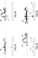
- FIGS 6A to 6H illustrate the different stages of preparation and installation on the seabed of the counterweight of the floating support structure.
- a barge 100 carrying in particular the basket 32 of the counterweight of the floating support structure and a dead body 104 is brought to sea on site.
- the dead body 104 is then lowered into the sea vertically from the barge 100 by a crane 106 ( Figure 6B ) then deposited on the seabed ( Figure 6C ).
- a remotely operated underwater vehicle 108 also called ROV for “Remotely Operated Vehicle” to supervise these operations and then to install a mooring line 110 on the deadweight 104 as shown in the Figure 6D .
- the mooring line 110 is a line connected to a temporary buoy on the one hand and to a mooring line 104 on the other hand, in order to provide an attachment point for the mooring line above the sea bed and below the final depth of the ballast basket.
- the float 12 of the floating support structure on which the mast 8 of a wind turbine 2 has been previously mounted is then towed by a tug 114 vertically above the basket 32 of the counterweight moored to the deadweight 104.
- This towing can be carried out by means of a tug connected to the main structure 18 of the float by one or more towing cables 116.
- the air present inside the flotation modules 112 is then released (and replaced by sea water).
- the ROV 108 can then be piloted to come and detach one after the other each flotation module emptied of its air to raise it in the barge 100 by means of a cable 118 of the crane 106 ( figure 6L ).
- the basket 32 of the counterweight acts on the ballast links 36 to tighten them and the mooring line 110 is slackened ( figure 6M ).
- the 110 rope can thus be easily disconnected from the counterweight basket by the ROV 108 ( figure 6N ).
- the float 12 and the wind turbine with the counterweight basket 32 connected by the ballast links are then towed by the tug 114 to the area where the offshore wind turbine is to be installed ( figure 6O ).
- a barge 120 comes to fill the basket 32 of the counterweight with the ballast material 34. This operation can be carried out using a tube 122 connecting the basket to the barge 120 ( Figure 6P ).
- the filling of the basket 32 of the counterweight with the ballast material 34 has the consequence of immersing the float 12, this immersion being controlled for allow the bottom of the float 12 of the floating support structure to be located at its immersion depth (typically 25 m).
- the counterweight may comprise a plurality of baskets each receiving a ballast material and which are positioned vertically one below the other while being regularly spaced (for example every 10m).
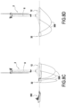
- a barge 200 comes to prepare the temporary area of the seabed in order to allow it to support the weight of the baskets filled with ballast from the counterweights of several floating support structures. This preparation consists of dumping on the seabed a fill material allowing the seabed to be able to support the weight of the baskets loaded with ballast material while maintaining an acceptable trim stability.
- a set of empty counterweight baskets 32 are lowered into the sea from the barge 200 and placed on the seabed using a crane 202 ( Figure 7B ).
- the counterweight baskets are placed one after the other as the barge advances, their number depending on the number of offshore wind turbines in the field to be installed ( Figure 7C ).
- the counterweight baskets 32 deposited on the seabed are then filled one after the other with ballast material 34 from the barge.
- temporary buoys 204 are connected to these baskets by means of the crane 202 of the barge and with the help of an ROV 206 ( Figure 7E ).
- Figure 7F shows the set of counterweight baskets each equipped with several temporary buoys 204.
- the float 12 of the floating support structure on which the mast 8 of a wind turbine has been previously mounted is then towed by a tug 208 vertically to a basket 32 of the counterweight.
- the main structure of the float is then connected to the basket of the counterweight by means of the ballast links 36 ( Figure 7G ).
- the barge 200 is brought in to disconnect the temporary buoys 204 from the basket 32 one after the other. This operation is carried out using the ROV 206 which disconnects each temporary buoy and brings it back on board the barge using a rope 210 ( Figure 7J ).
- the "ballastable" section of the central structure 26 of the float 12 is filled with sea water in order to adjust the waterline of the float to the desired immersion depth ( figure 7K ).
- this second embodiment (not shown in the figures), it is provided, instead of the step of preparing the temporary area of the seabed to enable it to support the weight of the baskets filled with ballast of the counterweights, to place on the seabed a system for lowering the counterweight.
- the raising system can thus completely or partially replace the effect of the rising tide on the relative position of the basket with respect to the bottom.
- the filling of the basket with ballast material can be done completely or partially on the basket placed on the raising system.
- additional ballast material is added once the basket has been detached from the raising system.
- This counterweight lowering system includes a wide base allowing the seabed to support the weight of the system and the empty counterweight basket of the floating support structure. Once the empty basket is lowered and placed on the base, the steps of the installation method in a manner similar to those previously described in connection with the Figures 7D to 7K .
- This embodiment variant is particularly interesting for the dynamic behavior of the counterweight during descent by linking the basket of the latter to the float by means of several catenary chains which makes it possible to decouple the movements of one and the other. In addition, no preparation of the seabed is required.
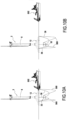
- a first tug 300 is used to tow at sea the float 12 of the floating support structure on which the mast of a wind turbine 2 has been previously mounted.
- the empty basket 32 of the counterweight of the floating support structure is towed independently by a second tug 302.
- the tugs 300, 302 manoeuvre to bring the float 12 closer to the basket 32 in order to allow the connections to be put in place between these two elements ( Figure 8B ).
- connections include the ballast links 36 connecting the basket 32 to each end of the tubes of the main structure of the float. This operation can be carried out using a dynamic positioning connection boat 306.
- ballast chains 308 are also connected between different points of the basket 32 and the main structure of the float 12. These ballast chains are for example three in number. During these operations, other retaining links (not shown in the figures) can be connected between the basket and the float to limit the distance of the float from the basket.
- the counterweight basket 32 is moved away from the float 12 and then gradually submerged by reducing the buoyancy of the temporary buoys 304 or by adding weight to the basket ( Figure 8E ).
- the immersion of the basket is continued until a first equilibrium position under the float ( Figure 8F ).
- the basket 32 of the counterweight is lowered further by continuously reducing or by compensating the flotation of the temporary buoys (or by adding ballast). It will be noted that the descent of the basket causes a reduction in the catenary of the ballast chains 308 under the basket and therefore in the weight that must be compensated by flotation. A process is envisaged in which the descent of the basket would automatically cause a reduction in its flotation and also a reduction in the ballast with an offset such that the speed of descent of the basket would be sufficiently low.
- the descent of the basket ends when the ballast links 36 are tensioned ( figure 8G ). If necessary, it can be envisaged that the descent stops automatically at desired depths (for example slightly before the ballast lines are tensioned to be able to ensure that their configuration is acceptable) ensuring that the loss of ballast is taken up by the loss of buoyancy at the desired depth.
- the counterweight basket 32 is filled with ballast material 34, for example from a ballast vessel 310 dumping the ballast material into the basket using a filling chute or tube 312 ( figure 8H ).
- This last step can be replaced by filling flotation elements linked to the basket in the case where the ballast was already present in this particular basket having a buoyancy reserve equivalent to the final weight seen by the ballast links.
- ballast chains 308 may be used to provide, where appropriate, an anchoring system for the floating support structure.
- the basket 32 is then lowered by a lifting system 402 installed at the level of the platform of the wind turbine 2 until the links ballast are stretched ( Figure 9B ).
- the float 12 connected to the counterweight is then towed to the wind turbine installation area and the basket 32 can then be filled with ballast material from a ballast boat 404 as previously described (i.e. by means of a tube 406 connecting the basket to the ballast boat - see Figure 9C ).
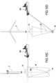
- the method comprises in a first step illustrated in the Figure 10A , the connection of ballast links 36 and ballast chains 500 between the basket 32 of the counterweight and the float 12.
- the float connected to the counterweight is towed at sea using a tug 502 to the area where the wind turbine is to be installed ( Figure 10B ).
- the empty basket 32 of the counterweight positioned under the floating support structure and its float is transported out to sea.
- the basket is submerged by ballasting in a progressive manner and the position of the basket is controlled by the catenary effect of the ballast chains to lower it into an equilibrium position under the float ( Figure 10C ).
- the basket 32 is then lowered below the float until the ballast ties 36 are taut, then it is filled with ballast material in order to submerge the float ( Figure 10D ). Finally, the float connected to the counterweight is towed to the wind turbine installation area.
- the method comprises in a first step illustrated in the Figure 11A , the transport at sea by a tug 600 of the basket 32 of the counterweight positioned removably inside a submersible floating support structure 602 to the wind turbine installation area.
- the basket 32 of the counterweight is prefilled with ballast material and the submersible structure of floating support 602 is filled with air at atmospheric pressure before departure in order to have the necessary buoyancy to keep the counterweight basket afloat.
- the counterweight basket 32 and the submersible floating support structure 602 are lowered underwater by a system of ballast chains 604 attached to the submersible floating support structure until reaching the desired depth.
- the ballast chains 604 have a predefined linear weight and are attached to the submersible floating support structure using a second tugboat 600'.
- Anchors 606 can be attached to the ballast chains 604 in order to stabilize the counterweight basket ( Figure 11C ).
- the wind turbine with its float 12 is then towed to the wind turbine installation area and positioned vertically above the counterweight basket 32 ( Figure 11D ).
- the ballast links 36 previously connected to the float 12 are then lowered and connected one by one to the counterweight basket 32 by means, for example, of a remote-controlled underwater vehicle 108 ( Figure 11E ).
- the submersible floating support structure 602 is gradually filled with water (replacing air) in order to lose buoyancy. During this filling, it descends with the counterweight basket until the ballast links 36 come under tension. The descent of the basket is then stopped and the weight of the basket is gradually transferred to the float 12 of the wind turbine which sees the ballast links 36 become taut under the weight of the counterweight basket ( Figure 11F ).
- the submersible floating support structure 602 When the entire weight of the basket is transferred to the wind turbine float, the submersible floating support structure 602 continues its descent in order to completely disengage from the counterweight basket 32. When it is filled with water, it is then located above the seabed at a distance of a few meters below the basket, the ballast chains 604 ensuring its maintenance in this position. The wind turbine and its counterweight can then be towed by the tug 600 to their installation area.
- the counterweight basket is only partially pre-filled with ballast material. After the wind turbine and its counterweight have been towed to the installation area, a vessel carrying the remaining ballast material positions itself near the wind turbine and fills the counterweight basket using flexible piping until the wind turbine reaches the required draft.
- the counterweight basket is provided with air ballast compartments.
- This basket is previously sunk in the port and the wind turbine float is positioned vertically above the basket in order to connect the ballast links by divers.
- Other temporary links shorter (about 5 meters) are connected between the float and the basket.
- the basket is then "deballasted" in order to stick to the wind turbine float.
- the whole thing is towed to a sheltered water site with a water depth of about 20m where the basket is ballasted until it becomes heavy and is taken up in tension by the temporary links.
- the whole thing is then towed to the wind turbine installation area where the wind turbine is moored.
- the temporary links are disconnected and the basket descends into the water column until it is taken up in tension by the ballast links.
- a vessel carrying the remaining ballast material positions itself alongside the wind turbine and fills the counterweight basket using flexible piping until the wind turbine reaches the required draft.
- this seventh embodiment can be implemented with a counterweight basket which is previously completely or only partially filled with ballast material.
Landscapes
- Engineering & Computer Science (AREA)
- Mechanical Engineering (AREA)
- Chemical & Material Sciences (AREA)
- Combustion & Propulsion (AREA)
- Ocean & Marine Engineering (AREA)
- Sustainable Development (AREA)
- Life Sciences & Earth Sciences (AREA)
- Sustainable Energy (AREA)
- General Engineering & Computer Science (AREA)
- Architecture (AREA)
- Structural Engineering (AREA)
- Transportation (AREA)
- Civil Engineering (AREA)
- Physics & Mathematics (AREA)
- Fluid Mechanics (AREA)
- Wind Motors (AREA)
- Optics & Photonics (AREA)
Description
- La présente invention se rapporte au domaine général des éoliennes offshore, c'est-à-dire implantées au large des côtes, et plus particulièrement aux structures de support flottant pour éoliennes offshore flottantes. L'invention concerne un procédé d'installation d'une éolienne offshore munie d'une telle structure de support.
- Une éolienne offshore a pour but d'utiliser l'énergie du vent afin de produire de l'électricité grâce à une turbine et à un générateur électrique. Il existe deux principaux types d'éoliennes offshore : les éoliennes fixes qui sont implantées sur les fonds marins (à de faibles profondeurs typiquement inférieures à 50m), et les éoliennes flottantes qui offrent l'avantage de pouvoir être construites sur terre et implantées dans des zones où la profondeur des fonds marins dépasse typiquement 50m.
- Les éoliennes flottantes comprennent une turbine généralement formée par un moteur à plusieurs pales rotatives à axe horizontal et un générateur électrique accouplé au moteur, le moteur et le générateur étant fixés à une extrémité supérieure d'un mât (ou pylône) vertical. L'extrémité inférieure du mât est quant à elle montée sur une structure de support flottant.
- Il existe quatre familles principales de structure de support flottant pour éolienne offshore : les barges, les plateformes semi-submersibles, les plateformes sur jambages tendus (ou plateformes TLP pour « Tension-Leg Platform » en anglais), et les plateformes « spar », c'est-à-dire des plateformes à fondation immergée et à ballast stabilisé qui sont dotées d'ancrages caténaires permettant de fixer l'éolienne par accrochage au fond marin. Parmi ces familles, les plateformes « spar » ont une structure relativement simple et reposent sur l'utilisation de technologies de fabrication et d'installation qui sont largement éprouvées.
- On pourra se référer notamment à la publication
WO 2005/021961 qui décrit un exemple de réalisation d'une plateforme « spar ». Lapublication WO 2006/121337 donne les détails d'un système d'ancrage d'une telle plateforme « spar », tandis que lapublication WO 2006/132539 est relative à un procédé d'installation en mer de cette plateforme. Les documentsJP 2015-009591 JP 2002-285951 US 2013/019792 ,EP 3,153,398 ,WO 2017/157399 ,WO 2016/161931 ,US 2003/168864 ,US 2008/240864 etUS 2017/051724 décrivent différents procédés d'installation d'une éolienne offshore. - Les plateformes « spar » présentent néanmoins un certain nombre d'inconvénients qui limitent fortement leur capacité d'utilisation dans le domaine de l'éolien offshore. Pour une éolienne de puissance élevée, il est nécessaire pour installer l'éolienne de disposer d'une profondeur minimale de l'ordre d'une centaine de mètres pour déployer une plateforme « spar ». Plus généralement, il est nécessaire de disposer d'une zone profonde et avec des conditions de mer relativement calmes pour gérer les phases critiques que sont le retournement de la plateforme de la position horizontale à la position verticale, le ballastage de la plateforme, et l'assemblage de la turbine par-dessus la plateforme. De plus, le recours à des plateformes « spar » requiert l'utilisation de bateaux-grues de grande capacité qui sont rares et onéreux pour installer les éoliennes sur les plateformes en mer. En outre, les plateformes « spar » présentent une grande traînée dans l'eau qui limite les vitesses de déplacement de ces plateformes dans le cas de leur remorquage.
- Ces inconvénients des plateformes « spar » limitent l'implantation d'éoliennes dans des zones disposant d'un fjord comme base logistique, ce qui en pratique se trouve dans peu d'endroits dans le monde, hormis en Norvège. De plus, les coûts atteignables par plateformes (dus notamment à la quantité d'acier très importante en regard des besoins de flottaison) sont limités à des valeurs élevées.
- Par ailleurs, la stabilité d'une éolienne flottante peut se décomposer en un problème de stabilité statique et un problème de stabilité dynamique. Le problème de la stabilité dynamique provient de forces non constantes dans le temps exerçant un couple déstabilisant pour la structure, induisant des mouvements. Ceux-ci sont liés aux fluctuations de la vitesse du vent sur l'éolienne ou aux vagues. L'énergie des vagues est essentiellement concentrée dans les premiers mètres de mer en-dessous de la surface libre. Les structures de support flottant majoritairement situées proche de la surface libre comme les barges ou les plateformes semi-submersibles sont fortement soumises aux vagues, de sorte que ces structures sont généralement concernées par des problèmes de stabilité dynamique.
- La présente invention a donc pour but principal de proposer un procédé d'installation d'une éolienne offshore munie d'une structure de support flottant qui ne présente pas les inconvénients précités.
- Ce but est atteint grâce à un procédé d'installation selon les revendications jointes.
- La structure de support flottant est ainsi constituée de deux éléments (le flotteur et le contrepoids) qui sont reliés entre eux par des liens de ballast : l'élément flottant est facile à transporter, son tirant d'eau en phase de construction et d'installation est faible, et il est compact et installable par des solutions de l'industrie offshore classique, le mât de l'éolienne et la nacelle pouvant être installés lors de la construction du flotteur.
- La structure de support flottant est remarquable notamment par la structure minimale du flotteur qui présente une forme de roue de vélo portée à l'horizontale dans laquelle la poussée d'Archimède qui s'exerce sur elle serait fournie en partie par la structure tubulaire centrale (correspondant au moyeu de la roue) et en partie par la structure de forme torique ou polygonale (correspondant au pneu de la roue).
- Par ailleurs, la forme particulière de la structure principale du flotteur permet d'obtenir une poussée qui est distribuée de façon continue autour de l'axe vertical, et non une poussée ponctuelle. De même, cette continuité de forme permet d'éviter que les efforts de la houle sur le flotteur ne varient avec les variations d'incidence, au contraire d'un flotteur qui serait à distribution ponctuelle.
- De plus, une telle structure permet de recourir à une profondeur d'immersion du flotteur qui est typiquement comprise entre 15 et 30 m. A une telle profondeur, du fait de la continuité de forme de la structure principale du flotteur, la structure de support flottant est quasiment transparente aux effets de la houle et des courants de surface, ce qui permet à l'éolienne de s'affranchir au maximum des problèmes de stabilité dynamique. De manière plus générale, l'éolienne utilisant une telle structure de support flottant pourra être implantée dans des zones économiquement accessibles car un minimum de profondeur d'eau de l'ordre de 70m suffira.
- De la sorte, la structure de support flottant permet l'exploitation de l'énergie éolienne à des fins de production d'électricité par des profondeurs d'eau supérieures à 70 m, sans limite haute de profondeur d'eau. L'éolienne utilisant une telle structure de support flottant pourra donc être implantée dans des zones économiquement accessibles.
- La structure de support flottant permet d'obtenir une stabilité accrue en rotation au niveau de l'éolienne, tant en mouvement qu'en accélération. La masse de matériaux pour la fabrication de cette structure de support est relativement faible, ce qui réduit les coûts de fabrication. Cette structure de support flottant est également compatible avec toutes les conceptions actuelles d'éoliennes flottantes, d'une puissance nominale allant jusqu'à 9,5 MW. La structure reste compatible avec les futures éoliennes d'une puissance de 10 à 15 MW et plus qui devraient entrer en production dans les années à venir.
- La structure de support flottant apporte une grande stabilité à l'éolienne supportée tant dans l'amplitude en mouvements de rotation que dans les accélérations angulaires. Cette stabilité relative aux conditions de houle, de vent et de courant rencontrées dans les différentes régions du monde reste compatible avec les spécifications techniques des éoliennes de l'industrie de l'éolien offshore.
- La structure de support flottant nécessite des niveaux de tensions minimisés dans les lignes d'ancrage retenant l'éolienne. De plus, elle est compatible avec les designs de câbles électriques d'export standards de l'industrie. Elle minimise l'emprise surfacique à la surface libre, ne gêne physiquement pas la navigation de petits navires à proximité immédiate, et minimise la masse de matériaux structurels utilisés par les structures de support flottant d'éoliennes.
- La fabrication de la structure de support flottant peut être réalisée dans les différents matériaux de structure. Elle utilise de préférence des matériaux métalliques et des procédés de fabrication standards de l'industrie de la construction de structure offshore. La structure de support flottant peut mettre en outre en oeuvre des matériaux non métalliques au niveau des tendons et du système d'ancrage qui sont dans la gamme des capacités standards actuelles de l'industrie.
- Par ailleurs, les dimensions, poids et tirant d'eau de la structure de support flottant sont compatibles avec la plupart des ports industriels et permettent l'assemblage des éléments de l'éolienne sur la structure de support amarrée bord à quai. L'assemblage de la structure de support et de l'éolienne peut être remorqué par flottaison par des conditions de mer compatibles avec la plupart des régions du globe. Ces opérations peuvent se faire en toute sécurité avec des conditions de risques opérationnels acceptables en utilisant des moyens d'installation classiques de l'industrie. Alternativement, l'assemblage de la structure de support flottant et de l'éolienne peut se faire en mer.
- Afin d'avoir une structure de support flottant stable par le poids et non par la forme, il convient que le point d'action de la poussée d'Archimède soit situé au-dessus de son centre de gravité. Le centre de gravité d'une éolienne étant situé assez haut au niveau du mât, du fait du poids de la nacelle et des pales, il convient d'ajouter un contrepoids dans le bas de la structure de support. Ce contrepoids va appliquer un couple résistant au niveau de la structure de support.
- D'autres caractéristiques et avantages de la présente invention ressortiront de la description faite ci-dessous, en référence aux dessins annexés qui en illustrent des exemples de réalisation dépourvus de tout caractère limitatif. Sur les figures :
- la
figure 1 est une vue de côté d'une éolienne offshore montée sur une structure de support flottant ; - la
figure 2 est une vue en perspective du flotteur de la structure de support flottant de lafigure 1 ; - la
figure 3 est une vue en perspective et en arraché d'un panier de la structure de support flottant de lafigure 1 ; - la
figure 4 est une vue de dessus du panier de lafigure 4 ; - la
figure 5 est une vue en coupe selon V-V de lafigure 4 ; - les
figures 6A à 6Q illustrent les différentes étapes d'un procédé d'installation d'une éolienne offshore munie d'une structure de support flottant ne relevant pas de l'invention ; - les
figures 7A à 7K illustrent les différentes étapes d'un procédé d'installation d'une éolienne offshore munie d'une structure de support flottant ne relevant pas de l'invention ; et - les
figures 8A à 8H illustrent les différentes étapes d'un procédé d'installation d'une éolienne offshore munie d'une structure de support flottant ne relevant pas de l'invention ; - les
figures 9A à 10C illustrent les différentes étapes d'un procédé d'installation d'une éolienne offshore munie d'une structure de support flottant selon l'invention ; - les
figures 10A à 10D illustrent les différentes étapes d'un procédé d'installation d'une éolienne offshore munie d'une structure de support flottant ne relevant pas de l'invention ; et - les
figures 11A à 11F illustrent les différentes étapes d'un procédé d'installation d'une éolienne offshore munie d'une structure de support flottant ne relevant pas de l'invention. - La
figure 1 représente, en vue de côté, une éolienne offshore flottante 2 implantée en mer au large des côtes. - De façon connue, une telle éolienne 2 comprend une turbine 4 généralement formée par un moteur à plusieurs pales rotatives à axe X-X sensiblement horizontal, et un générateur électrique 6 accouplé au moteur, le moteur et le générateur étant fixés à une extrémité supérieure d'un mât 8 (ou pylône) vertical. L'extrémité inférieure du mât 8 est quant à elle montée sur une structure de support flottant 10.
- La structure de support flottant 10 se compose d'un flotteur 12 qui est destiné à être en partie immergé (le niveau de la mer est symbolisé sur la
figure 1 par la ligne 14) et d'un contrepoids 16 qui est relié au flotteur 12 et qui est destiné à être immergé sous celui-ci. L'extrémité inférieure du mât 8 de l'éolienne vient s'assembler sur le flotteur 12 de la structure de support flottant. - Comme représenté sur la
figure 2 , le flotteur 12 comprend une structure principale 18 une forme polygonale à au moins cinq côtés, cette structure principale de forme polygonale étant formée par un assemblage de tubes 20 à section circulaire destinés à être immergés. Alternativement, la structure principale présente une forme torique. Dans cette variante, elle est formée par un unique tube à section circulaire. - Sur l'exemple illustré sur ces figures, la structure principale 18 du flotteur a une forme polygonale à six côtés. Une telle forme hexagonale représente le mode de réalisation préférentiel. En effet, cette forme offre le meilleur compromis en termes de structure et de comportement hydrodynamique.
- Les tubes 20 de la structure principale du flotteur sont à section circulaire et sont raccordés entre eux par l'intermédiaire de plaques de jonction 22 qui sont soudées aux extrémités des tubes. Ces tubes 20 sont raidis par un système de raidisseurs croisés (non représentés sur les figures) permettant d'optimiser le poids de la structure soumise à la pression hydrostatique. Les tubes sont compartimentés de sorte que la stabilité du système ne soit pas remise en cause si l'un de ces compartiments venait à se remplir d'eau de mer.
- Par ailleurs, la structure principale 18 du flotteur comprend en outre une structure de flottabilité additionnelle formée par un assemblage de flotteurs additionnels 24 qui sont montés sur les tubes 20 et qui permettent d'élever le franc-bord de l'ensemble flotteur et éolienne dans les phases de remorquage afin d'en améliorer la stabilité. Ces flotteurs additionnels peuvent être récupérés après la phase de remorquage ou être laissés sur le flotteur après son immersion.
- Le flotteur 12 comprend également une structure tubulaire centrale 26 centré sur un axe vertical Y-Y et ayant un diamètre adapté pour recevoir le mât 8 de l'éolienne. Cette structure centrale 26 comprend une section (non représentée sur les figures) qui est apte à être ballastée avec de l'eau de mer afin d'ajuster la ligne de flottaison du flotteur à la profondeur d'immersion souhaitée.
- Le flotteur 12 comprend encore une première série de bracons horizontaux 28 qui sont régulièrement répartis autour de l'axe vertical Y-Y et qui relient chaque extrémité des tubes 20 de la structure principale à la structure centrale 26, et plus particulièrement à la partie basse de celle-ci. Il y a autant de bracons horizontaux 28 que de tubes 20 formant la structure principale.
- Cette structure de bracons horizontaux 28, de type réticulée bien que très simple, permet de réduire les moments de flexion dans les tubes 20 de la structure principale à des moments secondaires. Ceci permet d'optimiser le mode de travail des tubes en traction-compression.
- Le flotteur 12 comprend encore une seconde série de bracons obliques 30 qui sont également régulièrement répartis autour de l'axe vertical Y-Y et qui relient chaque extrémité des tubes 20 de la structure principale à la structure centrale, et plus particulièrement à la partie haute de celle-ci, en formant un angle α compris entre 15° et 60° - et de préférence égal à 30° - avec les bracons horizontaux 28. Comme pour les bracons horizontaux, il existe autant de bracons obliques 30 que de tubes 20 formant la structure principale.
- Les bracons horizontaux 28 et obliques 30 se présentent sous la forme de tubes. La connexion entre les bracons et la structure principale du flotteur se fait au niveau des plaques de jonction 22. Cette technique d'assemblage permet de faciliter l'ajustement et la soudure des bracons de grandes dimensions.
- Par ailleurs, comme représenté sur les
figures 3 à 5 , le contrepoids 16 de la structure de support flottant comprend un panier 32 qui est apte à recevoir un matériau de ballast 34. - Afin de fournir un contrepoids de masse importante tout en réduisant les coûts, il convient d'utiliser un matériau pondéreux à la fois économique et compatible avec l'environnement marin. Dans un mode de réalisation préféré, le meilleur compromis pour le matériau de ballast 34 est trouvé avec des matériaux de ballast lourd. Typiquement, ce matériau de ballastage peut être de la magnétite stabilisée chimiquement afin d'être rendue compatible avec l'environnement. Alternativement, ce matériau de ballast peut être du matériau de remblais, du sable, de la grenaille de fonte ou du métal de récupération.
- Afin de pouvoir soutenir ce matériau de ballastage 34, il convient de le mettre dans un panier 32 conçu pour soutenir les efforts. Le diamètre du panier varie, selon les cas d'application, typiquement entre 8m et 22m et sa hauteur entre 6m et 10m.
- Le panier 32 du contrepoids est constitué d'une enveloppe cylindrique 32a terminée par un fond 32b bombé ou tronconique dans sa partie inférieure. Le poids est repris par des liens de ballast 36 (ou tendons) - de préférence au nombre de six - reliant le panier à chaque extrémité des tubes 20 de la structure principale.
- Plus précisément, ces liens de ballast 36 se rassemblent sur un connecteur central cylindrique 38 qui est situé au centre de l'enveloppe cylindrique 32a du panier dans sa partie supérieure.
- Le connecteur central 38 permet de concentrer le poids du contrepoids en un point central situé dans l'axe de la structure centrale 26 du flotteur. Cette concentration du poids en un point est un facteur primordial à l'efficacité du système de contrepoids, il permet au lest de rester immobile par rapport au flotteur quel que soit l'angle d'inclinaison tant que les liens de ballast 36 restent tous tendus.
- Comme représenté sur la
figure 1 , les liens de ballast 36 reliant le panier 32 à chaque extrémité des tubes 20 de la structure principale forment un angle β compris entre 15° et 45° avec l'axe vertical Y-Y. - L'angle β que forment les liens de ballast 36 avec l'axe vertical est de préférence donné par l'équation suivante :

- Le bas du flotteur 12 de la structure de support flottant est situé à une profondeur d'immersion typiquement de 25 m. La structure minimale permettant de reprendre des efforts de traction sont les liens de ballast 36. Le contrepoids est donc attaché au flotteur par autant de liens de ballast que la structure principale du flotteur a de côtés. Au niveau de celle-ci, les liens de ballast 36 sont connectés aux plaques de jonction 22.
- Les liens de ballast 36 peuvent être les plus légers possibles car leur masse ne joue qu'un rôle marginal dans la stabilité de la structure de support flottant. Ils doivent par ailleurs être capables de reprendre les efforts générés par le poids du contrepoids et avoir une élasticité et une déformation minimale dans le temps.
- Aussi, dans un mode de réalisation préféré, ces liens de ballast sont des cordages constitués de matériaux synthétiques ayant une faible élongation (typiquement du polyéthylène haute densité). Ces matériaux associent de bonnes propriétés mécaniques à un poids négatif dans l'eau (densité du matériau inférieure à 1). Alternativement, ces liens de ballast peuvent être des câbles, des chaînes ou des tubes métalliques.
- L'écartement des points d'accroche des liens de ballast 36 sur la structure principale 18 du flotteur est choisi de sorte que lorsque l'inclinaison de la direction du mât 8 de l'éolienne avec l'axe vertical Y-Y est maximale, tous les liens de ballast demeurent en tension. Les efforts auxquels est soumis le système sont augmentés d'un facteur de sécurité dépendant du cas d'application. De cette manière, l'inclinaison de l'éolienne sous l'action de la résultante de traînée de la force du vent et du poids de l'éolienne entraîne un transfert de tension des liens de ballast situés dans le sens opposé au vent vers ceux situés dans le sens du vent. Le contrepoids reste alors dans l'axe du mât de l'éolienne et cette structure souple se comporte mécaniquement comme une structure rigide, le lest restant fixe par rapport au flotteur. En d'autres termes, cette structure pendulaire réalise la fonction de contrepoids d'une plateforme « spar », tout en ayant une structure plus légère, transparente à la houle et installable avec l'éolienne fixée sur le flotteur au port.
- La structure de support flottant est conçue de manière à être stable sans système d'ancrage. Le système d'ancrage ne participe donc pas à la stabilité de la structure de support flottant. Cela engendre des niveaux de tension dans les lignes d'ancrages beaucoup plus faibles et des contraintes géotechniques sur les ancres amoindries.
- En liaison avec les
figures 6A à 6Q , on décrira un procédé d'installation (ne relevant pas de l'invention et présent uniquement à titre illustratif) d'une éolienne offshore munie d'une structure de support flottant telle que décrite précédemment. - Les
figures 6A à 6H illustrent les différentes étapes de préparation et d'installation au fond de la mer du contrepoids de la structure de support flottant. - Sur la
figure 6A , une barge 100 transportant notamment le panier 32 du contrepoids de la structure de support flottant et un corps mort 104 est amenée en mer sur site. Le corps mort 104 est alors descendu en mer à la verticale de la barge 100 par une grue 106 (figure 6B ) puis déposé sur le fond marin (figure 6C ). - Un véhicule sous-marin téléguidé 108 (appelé aussi ROV pour « Remotely Operated Vehicle ») pour superviser ces opérations et pour installer ensuite un orin 110 sur le corps mort 104 comme représenté sur la
figure 6D . Ici, l'orin 110 est un filin connecté à une bouée temporaire d'une part et à un corps mort 104 d'autre part, afin de fournir un point d'accroche au corps mort au-dessus du fond de la mer et en dessous de la profondeur définitive du panier de lest. - Au cours de l'étape suivante représentée par la
figure 6E , le panier 32 (vide) du contrepoids de la structure de support flottant est également descendu par la grue 106 de la barge vers le fond de la mer pour être connecté à l'orin 110 sous le pilotage du ROV 108 (figure 6F ). Des modules de flottaison 112 (au nombre de trois sur les figures) préalablement remplis d'air sont alors descendus en mer depuis la barge et fixés sur le panier 32 du contrepoids (figure 6G ). A l'issue de cette étape, cet attelage est déconnecté de la barge 100 et le ROV 108 est remonté à bord de celle-ci (figure 6H ). - Comme illustré sur les
figures 6I et6J , le flotteur 12 de la structure de support flottant sur lequel a été préalablement monté le mât 8 d'une éolienne 2 est alors remorqué par un remorqueur 114 à la verticale du panier 32 du contrepoids amarré au corps mort 104. Ce remorquage peut s'effectuer au moyen d'un remorqueur raccordé à la structure principale 18 du flotteur par un ou plusieurs câbles de remorquage 116. - Lorsque le flotteur 12 et l'éolienne 2 se trouvent à la verticale du panier 32 du contrepoids, le ROV 108 est à nouveau déployé pour venir connecter la structure principale du flotteur au panier au moyen des liens de ballast 36 (
figure 6J ). Afin de permettre de stabiliser la position du flotteur 12 au-dessus du panier du contrepoids, il pourra être nécessaire de recourir à plusieurs remorqueurs régulièrement espacés autour de celui-ci. - Au cours de l'étape suivante représentée par la
figure 6K , l'air présent à l'intérieur des modules de flottaison 112 est alors libéré (et remplacé par de l'eau de mer). Le ROV 108 peut alors être piloté pour venir détacher les uns après les autres chaque module de flottaison vidé de son air pour le remonter dans la barge 100 au moyen d'un filin 118 de la grue 106 (figure 6L ). - Une fois les modules de flottaison retirés, le panier 32 du contrepoids agit sur les liens de ballast 36 pour les tendre et l'orin 110 est quant à lui détendu (
figure 6M ). L'orin 110 peut ainsi être aisément déconnecté du panier du contrepoids par le ROV 108 (figure 6N ). Le flotteur 12 et l'éolienne avec le panier 32 du contrepoids connecté par les liens de ballast sont alors remorqués par le remorqueur 114 jusqu'à la zone d'implantation de l'éolienne en mer (figure 6O ). - Une fois le flotteur 12 et l'éolienne 2 positionnés et maintenus à la verticale de sa zone d'implantation choisie, une barge 120 vient remplir le panier 32 du contrepoids avec le matériau de ballastage 34. Cette opération peut être réalisée grâce à un tube 122 reliant le panier à la barge 120 (
figure 6P ). - Comme représenté sur la
figure 6Q , le remplissage du panier 32 du contrepoids par le matériau de ballastage 34 a pour conséquence de faire immerger le flotteur 12, cette immersion étant contrôlée pour permettre au bas du flotteur 12 de la structure de support flottant de se situer à sa profondeur d'immersion (typiquement de 25 m). - On notera que le contrepoids peut comprendre une pluralité de paniers recevant chacun un matériau de ballast et qui sont positionnés verticalement les uns en dessous des autres en étant régulièrement espacés (par exemple tous les 10m).
- En liaison avec les
figures 7A à 7K , on décrira à présent un procédé d'installation (ne relevant pas de l'invention et présent uniquement à titre illustratif) d'une éolienne offshore munie d'une structure de support flottant telle que décrite précédemment. - Au cours d'une première étape (
figure 7A ), une barge 200 vient préparer la zone temporaire du fond marin afin de permettre à celle-ci de supporter le poids des paniers remplis de ballast des contrepoids de plusieurs structures de support flottant. Cette préparation consiste à déverser sur le fond marin un matériau de remblais permettant au fond marin de pouvoir supporter le poids des paniers chargés de matériau de ballast tout en gardant une stabilité d'assiette acceptable. - Une fois le fond marin préparé, un ensemble de paniers 32 vides de contrepoids sont descendus en mer depuis la barge 200 et déposés sur le fond marin grâce à une grue 202 (
figure 7B ). Les paniers de contrepoids sont déposés les uns après les autres lors de l'avance de la barge, leur nombre dépendant du nombre d'éoliennes offshore du champ à installer (figure 7C ). - Comme représenté sur la
figure 7D , les paniers 32 de contrepoids déposés sur le fond marin sont alors remplis les uns après les autres par un matériau de ballast 34 à partir de la barge. Une fois les paniers remplis de matériau de ballast, des bouées temporaires 204 sont connectées sur ces paniers au moyen de la grue 202 de la barge et de l'aide d'un ROV 206 (figure 7E ). Lafigure 7F montre l'ensemble des paniers de contrepoids munis chacun de plusieurs bouées temporaires 204. - Au cours de l'étape suivante représentée par la
figure 7G , le flotteur 12 de la structure de support flottant sur lequel a été préalablement monté le mât 8 d'une éolienne est alors remorqué par un remorqueur 208 à la verticale d'un panier 32 du contrepoids. A marée basse, la structure principale du flotteur est alors connectée au panier du contrepoids au moyen des liens de ballast 36 (figure 7G ). - Par effet de la marée montante, le panier 32 du contrepoids se soulève du fond marin grâce aux liens de ballast 36 (
figure 7H ) afin de permettre un remorquage du flotteur 12 et du panier par le remorqueur 208 jusqu'à la zone d'implantation de l'éolienne en mer (figure 7I ). - Une fois le flotteur 12 et le panier du contrepoids positionnés et maintenus à la verticale de la zone d'implantation choisie, la barge 200 est amenée pour venir déconnecter les uns après les autres les bouées temporaire 204 du panier 32. Cette opération est réalisée grâce au ROV 206 qui vient déconnecter chaque bouée temporaire et la remonter à bord de la barge grâce à un filin 210 (
figure 7J ). - Lorsque toutes les bouées temporaires sont déconnectées, la section « ballastable » de la structure centrale 26 du flotteur 12 est remplie d'eau de mer afin d'ajuster la ligne de flottaison du flotteur à la profondeur d'immersion souhaitée (
figure 7K ). - Dans une variante de ce deuxième mode de réalisation (non représentée sur les figures), il est prévu, à la place de l'étape de préparation de la zone temporaire du fond marin pour lui permettre de supporter le poids des paniers remplis de ballast des contrepoids, de déposer sur le fond marin un système de descente du contrepoids.
- Dans cette variante, le système de rehausse peut ainsi remplacer totalement ou partiellement l'effet de la marée montante sur la position relative du panier par rapport au fond. Selon les cas, le remplissage du panier par du matériau de ballast peut se faire entièrement ou partiellement sur le panier posé sur le système de rehausse. Dans le cas où le remplissage se fait partiellement sur le panier posé sur le système de rehausse un complément de matériau de ballast est effectué une fois le panier décollé du système de rehausse.
- Ce système de descente du contrepoids comprend une embase large permettant au fond marin de supporter le poids du système et le panier vide du contrepoids de la structure de support flottant. Une fois le panier vide descendu et posé sur l'embase, les étapes du procédé d'installation de manière similaire à celles décrites précédemment en liaison avec les
figures 7D à 7K . - Cette variante de réalisation peut être préférée car elle présente l'avantage de s'affranchir de la marée.
- En liaison avec les
figures 8A à 8H , on décrira un mode de réalisation du procédé d'installation (ne relevant pas de l'invention et présent uniquement à titre illustratif) d'une éolienne offshore munie d'une structure de support flottant telle que décrite précédemment. - Cette variante de réalisation est particulièrement intéressante pour le comportement dynamique du contrepoids pendant la descente en liant le panier de celui-ci au flotteur par l'intermédiaire de plusieurs chaînes en caténaire ce qui permet de découpler les mouvements de l'un et de l'autre. De plus, aucune préparation du fond de la mer n'est requise.
- Selon une première étape illustrée par la
figure 8A , un premier remorqueur 300 est utilisé pour remorquer en mer le flotteur 12 de la structure de support flottant sur lequel a été préalablement monté le mât d'une éolienne 2. Le panier 32 vide du contrepoids de la structure de support flottant est quant à lui remorqué indépendamment par un second remorqueur 302. - On notera que pour faciliter le remorquage du panier du contrepoids, celui-ci peut être muni de bouées temporaires 304. On notera également que les deux remorqueurs 300, 302 sont équipés chacun d'un système de positionnement dynamique.
- Une fois parvenus à la zone d'implantation en mer de l'éolienne, les remorqueurs 300, 302 manoeuvrent pour rapprocher le flotteur 12 du panier 32 afin de permettre la mise en place des connexions entre ces deux éléments (
figure 8B ). - Ces connexions sont notamment les liens de ballast 36 reliant le panier 32 à chaque extrémité des tubes de la structure principale du flotteur. Cette opération peut être réalisée à l'aide d'un bateau de connexion en positionnement dynamique 306.
- Comme représenté sur la
figure 8C , des chaînes de lestage 308 sont également connectées entre différents points du panier 32 et la structure principale du flotteur 12. Ces chaînes de lestage sont par exemple au nombre de trois. Au cours de ces opérations, d'autres liens de retenue (non représentés sur les figures) peuvent être connectés entre le panier et le flotteur pour limiter l'éloignement du flotteur par rapport au panier. - Au cours de l'étape suivante, le panier 32 du contrepoids est éloigné du flotteur 12 puis immergé progressivement par réduction de la flottaison des bouées temporaires 304 ou par ajout de poids dans le panier (
figure 8E ). L'immersion du panier est poursuivie jusqu'à une première position d'équilibre sous le flotteur (figure 8F ). - Le panier 32 du contrepoids est descendu davantage en réduisant de manière continue ou par pallier la flottaison des bouées temporaires (ou par ajout de lest). On notera que la descente du panier entraîne une réduction de la caténaire des chaînes de lestage 308 sous le panier et donc du poids qu'il faut compenser par flottaison. Il est envisagé un processus dans lequel la descente du panier provoquerait automatiquement la baisse de sa flottaison et une baisse également du lest avec un décalage tel que la vitesse de descente du panier serait suffisamment faible.
- La descente du panier se termine au moment où les liens de ballast 36 sont tendus (
figure 8G ). Si besoin, il peut être envisagé que la descente s'arrête automatiquement à des profondeurs voulues (par exemple légèrement avant que les liens de ballast se tendent pour pouvoir s'assurer que leur configuration est acceptable) en s'assurant que la perte de lest soit rattrapée par la perte de flottaison à la profondeur voulue. - Enfin, le panier 32 du contrepoids est rempli par le matériau de ballast 34, par exemple à partir d'un bateau de ballastage 310 déversant le matériau de ballast dans le panier à l'aide d'une gouttière ou tube de remplissage 312 (
figure 8H ). - Cette dernière étape peut être remplacée par le remplissage d'éléments de flottaison liés au panier dans le cas où le lest était déjà présent dans ce panier particulier ayant une réserve de flottabilité équivalente au poids final vu par les liens de ballast.
- On notera que les chaînes de lestage 308 pourront être utilisées pour servir pour réaliser le cas échéant un système d'ancrage de la structure de support flottant.
- En liaison avec les
figures 9A à 9C , on décrira un mode de réalisation du procédé d'installation selon l'invention d'une éolienne offshore munie d'une structure de support flottant telle que décrite précédemment. - Dans ce mode de réalisation de l'invention, il est prévu de transporter en mer conjointement par un remorqueur 400 le flotteur 12 avec son panier 32 de contrepoids vide de lest positionné en dessous de la structure de support flottant jusqu'à la zone d'implantation de l'éolienne (
figure 9A ). - Le panier 32 est alors descendu par un système de levage 402 installé au niveau de la plateforme de l'éolienne 2 jusqu'à ce que les liens de ballast soient tendus (
figure 9B ). Le flotteur 12 connecté au contrepoids est ensuite remorqué jusqu'à la zone d'implantation de l'éolienne et le panier 32 peut alors être rempli avec du matériau de ballast à partir d'un bateau de ballastage 404 comme décrit précédemment (c'est-à-dire au moyen d'un tube 406 reliant le panier au bateau de ballastage - voir lafigure 9C ). - En liaison avec les
figures 10A à 10D , on décrira maintenant un mode de réalisation du procédé d'installation (ne relevant pas de l'invention et présent uniquement à titre illustratif) d'une éolienne offshore munie d'une structure de support flottant telle que définie précédemment. - Dans ce mode de réalisation, le procédé comprend dans une première étape illustrée sur la
figure 10A , la connexion de liens de ballast 36 et de chaînes de lestage 500 entre le panier 32 du contrepoids et le flotteur 12. Une fois cette opération effectuée, le flotteur connecté au contrepoids est remorqué en mer à l'aide d'un remorqueur 502 jusqu'à la zone d'implantation de l'éolienne (figure 10B ). Conjointement, le panier 32 vide du contrepoids positionné sous la structure de support flottant et de son flotteur est transporté en mer. - Le panier est immergé par ballastage de manière progressive et la position du panier est contrôlée par l'effet caténaire des chaînes de lestage pour le descendre dans une position d'équilibre sous le flotteur (
figure 10C ). - Le panier 32 est alors descendu sous le flotteur jusqu'à ce que les liens de ballast 36 soient tendus, puis il est rempli par un matériau de ballast afin d'immerger le flotteur (
figure 10D ). Enfin, le flotteur connecté au contrepoids est remorqué jusqu'à la zone d'implantation de l'éolienne. - En liaison avec les
figures 11A à 11F , on décrira maintenant un mode de réalisation du procédé d'installation (ne relevant pas de l'invention et présent uniquement à titre illustratif) d'une éolienne offshore munie d'une structure de support flottant telle que définie précédemment. - Dans ce mode de réalisation, le procédé comprend dans une première étape illustrée sur la
figure 11A , le transport en mer par un remorqueur 600 du panier 32 du contrepoids positionné de manière amovible à l'intérieur d'une structure submersible de support flottant 602 jusqu'à la zone d'implantation de l'éolienne. - Dans ce mode de réalisation, le panier 32 du contrepoids est préalablement rempli de matériau de ballast et la structure submersible de support flottant 602 est remplie d'air à la pression atmosphérique avant le départ afin d'avoir la flottabilité nécessaire pour maintenir en flottaison le panier du contrepoids.
- Comme représenté sur les
figures 11B et11C , une fois arrivé sur la zone d'implantation de l'éolienne, le panier 32 de contrepoids et la structure submersible de support flottant 602 sont descendus sous l'eau par un système de chaînes de ballast 604 accrochées à la structure submersible de support flottant jusqu'à atteindre la profondeur désirée. A cet effet, les chaînes de ballast 604 ont un poids linéaire prédéfini et sont accrochées à la structure submersible de support flottant à l'aide d'un second remorqueur 600'. Des ancres 606 peuvent être accrochées aux chaînes de ballast 604 afin de stabiliser le panier de contrepoids (figure 11C ). - L'éolienne avec son flotteur 12 est ensuite remorquée jusqu'à la zone d'implantation de l'éolienne et positionnée à la verticale du panier 32 de contrepoids (
figure 11D ). Les liens de ballast 36 préalablement connectés au flotteur 12 sont alors descendus et connectés un par un au panier 32 de contrepoids au moyen par exemple d'un véhicule sous-marin téléguidé 108 (figure 11E ). - Au cours de l'étape suivante, la structure submersible de support flottant 602 est progressivement remplie d'eau (en remplacement de l'air) afin de perdre de la flottabilité. Au cours de ce remplissage, elle descend avec le panier de contrepoids jusqu'à ce que les liens de ballast 36 entrent en tension. La descente du panier est alors stoppée et le poids du panier est progressivement transféré au flotteur 12 de l'éolienne qui voit les liens de ballast 36 se tendre sous le poids du panier du contrepoids (
figure 11F ). - Quand l'intégralité du poids du panier est transférée au flotteur de l'éolienne, la structure submersible de support flottant 602 poursuit sa descente afin de se désengager complètement du panier 32 de contrepoids. Lorsqu'elle se retrouve remplie d'eau, elle se situe alors au-dessus du fond marin à une distance de quelques mètres sous le panier, les chaînes de ballast 604 assurant son maintien dans cette position. L'éolienne et son contrepoids peuvent ensuite être remorquées par le remorqueur 600 jusqu'à leur zone d'implantation.
- Dans une variante de réalisation (non représentée sur les figures) de ce mode de réalisation, le panier de contrepoids n'est que partiellement rempli au préalable de matériau de ballast. Après que l'éolienne et son contrepoids aient été remorqués sur la zone d'implantation, un navire transportant le reste du matériau de ballast se positionne aux abords de l'éolienne et remplit le panier de contrepoids à l'aide d'une tuyauterie flexible jusqu'à ce que l'éolienne atteigne le tirant d'eau requis.
- Dans un mode de réalisation (non représenté sur les figures) du procédé d'installation (ne relevant pas de l'invention et présent uniquement à titre illustratif) d'une éolienne offshore munie d'une structure de support flottant telle que définie précédemment, le panier de contrepoids est doté de compartiments de ballast d'air.
- Ce panier est préalablement coulé dans le port et le flotteur de l'éolienne est positionné à la verticale du panier afin de connecter les liens de ballast par plongeurs. D'autre liens temporaires, plus courts (d'environ 5 mètres) sont connectés entre le flotteur et le panier. Le panier est ensuite « déballasté » afin de venir se coller au flotteur de l'éolienne. L'ensemble est remorqué jusqu'à un site en eau abrité d'environ 20m de profondeur d'eau où le panier est ballasté jusqu'à ce qu'il devienne pesant et soit repris en tension par les liens temporaires. L'ensemble est alors remorqué jusqu'à la zone d'implantation de l'éolienne où l'éolienne est amarrée. Les liens temporaires sont déconnectés et le panier descend dans la colonne d'eau jusqu'à être repris en tension par les liens de ballast.
- Par la suite, un navire transportant le reste du matériau de ballast se positionne aux abords de l'éolienne et remplit le panier de contrepoids à l'aide d'une tuyauterie flexible jusqu'à ce que l'éolienne atteigne le tirant d'eau requis.
- On notera que comme pour le sixième mode de réalisation, ce septième mode de réalisation peut être mis en oeuvre avec un panier de contrepoids qui est préalablement complètement ou partiellement seulement rempli de matériau de ballast.
Claims (4)
- Procédé d'installation d'une éolienne offshore munie d'une structure de support flottante qui comprend un flotteur (12) destiné à être en partie immergé et sur lequel est destiné à être assemblé un mât (8) d'éolienne, et un contrepoids (16) relié au flotteur et destiné à être immergé sous le flotteur, le flotteur (12) comprenant :une structure principale (18) de forme torique ou polygonale à au moins cinq côtés qui est formée par au moins un tube (20) destiné à être immergé ;une structure tubulaire centrale (26) ayant un diamètre adapté pour recevoir le mât (8) de l'éolienne et comprenant une section apte à être ballastée afin d'ajuster la ligne de flottaison du flotteur ;une première série de bracons horizontaux (28) régulièrement répartis autour d'un axe vertical et reliant la structure principale à la structure centrale ; etune seconde série de bracons obliques (30) régulièrement répartis autour d'un axe vertical (Y-Y) et reliant la structure principale à la structure centrale en formant un angle (α) compris entre 15° et 60° avec les bracons horizontaux (28) ;le contrepoids (16) comprenant un panier (32) apte à recevoir un matériau de ballast (34) et des liens de ballast (36) reliant le panier à la structure principale (18) du flotteur en formant un angle (β) compris entre 15° et 45° avec l'axe vertical (Y-Y),le procédé comprenant les étapes successives de :transport en mer conjoint d'un panier (32) du contrepoids (16) positionné sous la structure de support flottanteet de son flotteur (12) ;descente verticale du panier au moyen d'un système de levage (402) intégré au niveau du flotteur ;remorquage en mer du flotteur connecté au contrepoids jusqu'à la zone d'implantation de l'éolienne ; etremplissage par un matériau de ballast du panier du contrepoids suspendu à la structure du flotteur.
- Procédé selon la revendication 1, dans lequel l'étape de descente verticale du panier est réalisée jusqu'à ce que les liens de ballast (36) soient tendus.
- Procédé selon l'une des revendications 1 et 2, dans lequel l'étape de transport en mer s'effectue avec le panier (32) du contrepoids (16) vide de lest.
- Procédé selon l'une quelconque des revendications 1 à 3, dans lequel l'étape de remplissage est réalisée à partir d'un bateau de ballastage (404) déversant le matériau de ballast dans le panier à l'aide d'une gouttière ou d'un tube de remplissage.
Applications Claiming Priority (3)
| Application Number | Priority Date | Filing Date | Title |
|---|---|---|---|
| FR1761342A FR3074138B1 (fr) | 2017-11-29 | 2017-11-29 | Structure de support flottant pour eolienne offshore et procede d'installation d'une eolienne munie d'une telle structure de support |
| EP18827192.8A EP3717343B1 (fr) | 2017-11-29 | 2018-11-27 | Structure de support flottant pour éolienne offshore et procédé d'installation d'une éolienne munie d'une telle structure de support |
| PCT/FR2018/053006 WO2019106283A1 (fr) | 2017-11-29 | 2018-11-27 | Structure de support flottant pour éolienne offshore et procédé d'installation d'une éolienne munie d'une telle structure de support |
Related Parent Applications (2)
| Application Number | Title | Priority Date | Filing Date |
|---|---|---|---|
| EP18827192.8A Division EP3717343B1 (fr) | 2017-11-29 | 2018-11-27 | Structure de support flottant pour éolienne offshore et procédé d'installation d'une éolienne munie d'une telle structure de support |
| EP18827192.8A Division-Into EP3717343B1 (fr) | 2017-11-29 | 2018-11-27 | Structure de support flottant pour éolienne offshore et procédé d'installation d'une éolienne munie d'une telle structure de support |
Publications (2)
| Publication Number | Publication Date |
|---|---|
| EP3854671A1 EP3854671A1 (fr) | 2021-07-28 |
| EP3854671B1 true EP3854671B1 (fr) | 2024-08-14 |
Family
ID=61027965
Family Applications (6)
| Application Number | Title | Priority Date | Filing Date |
|---|---|---|---|
| EP21162736.9A Active EP3854671B1 (fr) | 2017-11-29 | 2018-11-27 | Procédé d'installation d'une éolienne offshore munie d'une structure de support flottant |
| EP18827192.8A Active EP3717343B1 (fr) | 2017-11-29 | 2018-11-27 | Structure de support flottant pour éolienne offshore et procédé d'installation d'une éolienne munie d'une telle structure de support |
| EP21162740.1A Active EP3854672B1 (fr) | 2017-11-29 | 2018-11-27 | Procédé d'installation d'une éolienne offshore munie d'une structure de support flottant |
| EP21162730.2A Active EP3854669B1 (fr) | 2017-11-29 | 2018-11-27 | Procédé d'installation d'une éolienne offshore munie d'une structure de support flottant |
| EP21162744.3A Active EP3854673B1 (fr) | 2017-11-29 | 2018-11-27 | Procédé d'installation d'une éolienne offshore munie d'une structure de support flottant |
| EP21162733.6A Active EP3854670B1 (fr) | 2017-11-29 | 2018-11-27 | Procédé d'installation d'une éolienne offshore munie d'une structure de support flottant |
Family Applications After (5)
| Application Number | Title | Priority Date | Filing Date |
|---|---|---|---|
| EP18827192.8A Active EP3717343B1 (fr) | 2017-11-29 | 2018-11-27 | Structure de support flottant pour éolienne offshore et procédé d'installation d'une éolienne munie d'une telle structure de support |
| EP21162740.1A Active EP3854672B1 (fr) | 2017-11-29 | 2018-11-27 | Procédé d'installation d'une éolienne offshore munie d'une structure de support flottant |
| EP21162730.2A Active EP3854669B1 (fr) | 2017-11-29 | 2018-11-27 | Procédé d'installation d'une éolienne offshore munie d'une structure de support flottant |
| EP21162744.3A Active EP3854673B1 (fr) | 2017-11-29 | 2018-11-27 | Procédé d'installation d'une éolienne offshore munie d'une structure de support flottant |
| EP21162733.6A Active EP3854670B1 (fr) | 2017-11-29 | 2018-11-27 | Procédé d'installation d'une éolienne offshore munie d'une structure de support flottant |
Country Status (12)
| Country | Link |
|---|---|
| US (1) | US11383799B2 (fr) |
| EP (6) | EP3854671B1 (fr) |
| KR (1) | KR102317990B1 (fr) |
| AU (1) | AU2018376719B2 (fr) |
| ES (4) | ES2965262T3 (fr) |
| FR (1) | FR3074138B1 (fr) |
| MX (1) | MX2020005541A (fr) |
| PH (1) | PH12020550612A1 (fr) |
| PT (2) | PT3854669T (fr) |
| SA (1) | SA520412052B1 (fr) |
| WO (1) | WO2019106283A1 (fr) |
| ZA (1) | ZA202002483B (fr) |
Families Citing this family (38)
| Publication number | Priority date | Publication date | Assignee | Title |
|---|---|---|---|---|
| FR3074138B1 (fr) * | 2017-11-29 | 2021-08-27 | Saipem Sa | Structure de support flottant pour eolienne offshore et procede d'installation d'une eolienne munie d'une telle structure de support |
| CN112302056B (zh) * | 2019-06-10 | 2024-10-22 | 江苏道达海上风电工程科技有限公司 | 一种用于深海风机基础防护防冲刷与压载的充沙袋 |
| DE102019118564B4 (de) | 2019-07-09 | 2021-03-11 | Aerodyn Consulting Singapore Pte Ltd | Windenergieanlage mit einem eine Mehrzahl von Auftriebskörpern aufweisenden schwimmenden Fundament |
| DE102019122110A1 (de) | 2019-08-16 | 2021-02-18 | EnBW Energie Baden-Württemberg AG | Schwimmende Windenergieanlage mit integriertem Umspannwerk |
| NO345641B2 (en) * | 2019-09-25 | 2021-05-25 | Clovers As | Floating Wind Turbine Platform |
| CN114555459B (zh) | 2019-09-25 | 2024-07-16 | 三叶草股份有限公司 | 浮动金属平台 |
| JP7515915B2 (ja) * | 2019-11-12 | 2024-07-16 | ベリディ マリタイム ソシエダッド リミターダ | 海洋設備を支持するための構造体及びその実施方法 |
| EP4115081B1 (fr) * | 2020-03-06 | 2023-11-01 | Vestas Wind Systems A/S | Procédé d'installation de pales de rotor sur une éolienne en mer |
| KR102144423B1 (ko) * | 2020-03-11 | 2020-08-12 | (주)삼원밀레니어 | 반잠수식 풍력발전기 및 이의 설치 및 해체 방법 |
| CN115768687A (zh) | 2020-04-16 | 2023-03-07 | 缅因大学系统理事会 | 装配和部署浮动海上风力涡轮机平台的方法 |
| FR3110540B1 (fr) | 2020-05-25 | 2023-02-10 | Saipem Sa | Procédé et système de mise en tension d’un système hyperstatique |
| DK181207B1 (en) * | 2020-06-04 | 2023-04-28 | Stiesdal Offshore As | Positioning of a keel of a floating structure and a floating structure with keel |
| IT202000015913A1 (it) | 2020-07-01 | 2022-01-01 | Saipem Spa | Gruppo offshore, sistema e metodo di produzione di idrocarburi comprendente tale gruppo offshore |
| NO346590B1 (en) * | 2020-09-18 | 2022-10-17 | Fred Olsen Ocean Ltd | Wind turbine with floating foundation |
| FR3117553B1 (fr) * | 2020-12-10 | 2022-11-04 | Bourbon Offshore Gaia | Procédé d’assemblage d’un parc éolien offshore flottant |
| SE545543C2 (en) * | 2021-01-28 | 2023-10-17 | Tjololo Ab | Semi-submersible Wind Power Platform |
| ES2938666B2 (es) | 2021-10-07 | 2023-11-22 | Sener Ing & Sist | Plataforma flotante semisumergible para aerogenerador marino |
| CN113864123A (zh) * | 2021-10-15 | 2021-12-31 | 西安热工研究院有限公司 | 一种海上移动风力发电站 |
| CN114148492A (zh) * | 2021-11-19 | 2022-03-08 | 中国科学院深海科学与工程研究所 | 一种深海着陆器 |
| DK181346B1 (en) * | 2022-02-14 | 2023-08-22 | Stiesdal Offshore As | Method for assembling braces by casted nodes in an offshore support structure |
| US12583560B2 (en) | 2022-07-08 | 2026-03-24 | Mighty Waves Energy, Llc. | Floating power generation platform |
| US12584461B2 (en) | 2022-09-08 | 2026-03-24 | Jason C. FABRE | Floating offshore wind turbine apparatus and installation method |
| FR3139794A1 (fr) | 2022-09-21 | 2024-03-22 | Saipem S.A. | Structure de support flottant à multiples colonnes centrales pour éolienne offshore et procédé d’assemblage d’une telle structure |
| DE102023100270A1 (de) | 2023-01-09 | 2024-07-11 | Universität Rostock, Körperschaft des öffentlichen Rechts | Schwimmende Plattform |
| NO348315B1 (en) * | 2023-02-13 | 2024-11-18 | Odfjell Oceanwind As | Floating wind turbine foundation |
| FR3146305A1 (fr) | 2023-03-03 | 2024-09-06 | Saipem S.A. | Procédé de production en série de flotteurs pour éoliennes offshore |
| FR3146456A1 (fr) | 2023-03-09 | 2024-09-13 | Saipem S.A. | Contrepoids pour flotteur semi-submersible d’éolienne offshore et son procédé d’installation |
| FR3149292B1 (fr) * | 2023-06-02 | 2025-06-06 | Saipem Sa | Flotteur semi-submersible à contrepoids pendulaire pour éolienne offshore et son procédé d’installation |
| CN119079019A (zh) * | 2023-06-06 | 2024-12-06 | 上海交通大学 | 变长度恒张力系泊系统及方法 |
| CN116902156A (zh) * | 2023-07-21 | 2023-10-20 | 中交第一航务工程局有限公司 | 漂浮式基础结构及其应用 |
| US12291310B1 (en) | 2023-09-19 | 2025-05-06 | Terasun Co. Ltd. | Floating platform, anchor container structure, floating structure, and installation method for installing floating platform on water |
| JP7432975B1 (ja) | 2023-09-19 | 2024-02-19 | 株式会社テラサン | 浮体式プラットフォーム、アンカー容器体、浮体、浮体式プラットフォームを水上に設置するための設置方法 |
| CN117090738A (zh) * | 2023-10-09 | 2023-11-21 | 上海易斯特海洋工程技术有限公司 | 泥浮式海上风机系统的辅助运输设备 |
| EP4549696A1 (fr) | 2023-11-03 | 2025-05-07 | Saipem S.p.A. | Système de production d'hydrocarbures en mer |
| FR3155805A1 (fr) | 2023-11-27 | 2025-05-30 | Saipem S.A. | Procédé de positionnement et d’alignement de blocs de flotteur semi-submersible pour éolienne offshore |
| FR3158305B1 (fr) | 2024-01-11 | 2026-01-16 | Saipem Sa | Procédé de raccordement de deux blocs d’une structure offshore |
| FR3158700A1 (fr) | 2024-01-30 | 2025-08-01 | Saipem S.A. | Porteur mutualisé pour l’installation d’outils destinés à la production en série de structures métalliques, notamment de fondations fixes ou flottantes pour éoliennes offshore |
| WO2025188350A1 (fr) * | 2024-03-08 | 2025-09-12 | University Of Virginia Patent Foundation | Plateformes d'éolienne fixe-flottantes et flottantes à base d'anneau |
Family Cites Families (16)
| Publication number | Priority date | Publication date | Assignee | Title |
|---|---|---|---|---|
| JP2002285951A (ja) * | 2001-03-23 | 2002-10-03 | Hitachi Zosen Corp | 洋上風力発電の浮体式基礎構造物 |
| AU2003213772A1 (en) * | 2002-03-08 | 2003-09-22 | Ocean Wind Energy Systems | Offshore wind turbine |
| NO20033807D0 (no) | 2003-08-27 | 2003-08-27 | Norsk Hydro As | Vindmölle for anvendelse offshore |
| NO325261B1 (no) | 2005-05-06 | 2008-03-17 | Norsk Hydro As | Forankringsarrangement for flytende vindturbininstallasjoner. |
| NO20052704L (no) | 2005-06-06 | 2006-12-07 | Norsk Hydro As | Flytende vindturbininstallasjon. |
| US20080240864A1 (en) * | 2007-04-02 | 2008-10-02 | Ups Wind Management , Llc | Assembly, transportation and installation of deepwater windpower plant |
| CA2699380A1 (fr) | 2007-09-13 | 2009-03-19 | Floating Windfarms Corporation | Eolienne a axe vertical au large, systemes et procedes associes |
| US20090304453A1 (en) | 2007-11-08 | 2009-12-10 | Stewart Hardison | Mooring habitat structure |
| ES2727415T3 (es) * | 2010-11-04 | 2019-10-16 | Univ Maine System | Sistema de plataforma y torre de turbina eólica de material compuesto híbrido flotante |
| DE102011052024B4 (de) * | 2011-07-21 | 2016-06-23 | Jähnig GmbH Felssicherung und Zaunbau | Schimmendes Bauwerk |
| JP6366124B2 (ja) * | 2013-06-26 | 2018-08-01 | ジャパンマリンユナイテッド株式会社 | 浮体構造物 |
| ES2555500B1 (es) * | 2014-05-27 | 2016-12-13 | Sea Wind Towers Sl | Obra flotante y procedimiento de instalación de la misma |
| EP3153399A4 (fr) | 2014-05-27 | 2018-05-30 | Esteyco S.A.P. | Sous-structure flottante pour aérogénérateur et son procédé d'installation |
| CN104802952B (zh) * | 2015-04-06 | 2017-05-03 | 陈佳宇 | 软质浮体单元及基于该浮体单元的管线杆、发电站和充气模型 |
| JP2019509217A (ja) * | 2016-03-15 | 2019-04-04 | スティーズダル オフショアー テクノロジーズ アクティーゼルスカブ | 浮体式風力タービン及びこのような浮体式風力タービンの設置方法 |
| FR3074138B1 (fr) * | 2017-11-29 | 2021-08-27 | Saipem Sa | Structure de support flottant pour eolienne offshore et procede d'installation d'une eolienne munie d'une telle structure de support |
-
2017
- 2017-11-29 FR FR1761342A patent/FR3074138B1/fr active Active
-
2018
- 2018-11-27 AU AU2018376719A patent/AU2018376719B2/en active Active
- 2018-11-27 EP EP21162736.9A patent/EP3854671B1/fr active Active
- 2018-11-27 PT PT211627302T patent/PT3854669T/pt unknown
- 2018-11-27 ES ES21162744T patent/ES2965262T3/es active Active
- 2018-11-27 ES ES21162730T patent/ES2965223T3/es active Active
- 2018-11-27 EP EP18827192.8A patent/EP3717343B1/fr active Active
- 2018-11-27 MX MX2020005541A patent/MX2020005541A/es unknown
- 2018-11-27 WO PCT/FR2018/053006 patent/WO2019106283A1/fr not_active Ceased
- 2018-11-27 EP EP21162740.1A patent/EP3854672B1/fr active Active
- 2018-11-27 KR KR1020207013413A patent/KR102317990B1/ko active Active
- 2018-11-27 ES ES21162736T patent/ES2993885T3/es active Active
- 2018-11-27 EP EP21162730.2A patent/EP3854669B1/fr active Active
- 2018-11-27 EP EP21162744.3A patent/EP3854673B1/fr active Active
- 2018-11-27 EP EP21162733.6A patent/EP3854670B1/fr active Active
- 2018-11-27 ES ES18827192T patent/ES2929103T3/es active Active
- 2018-11-27 PT PT188271928T patent/PT3717343T/pt unknown
- 2018-12-27 US US16/767,474 patent/US11383799B2/en active Active
-
2020
- 2020-05-06 ZA ZA2020/02483A patent/ZA202002483B/en unknown
- 2020-05-11 PH PH12020550612A patent/PH12020550612A1/en unknown
- 2020-05-27 SA SA520412052A patent/SA520412052B1/ar unknown
Also Published As
| Publication number | Publication date |
|---|---|
| ES2993885T3 (en) | 2025-01-13 |
| WO2019106283A1 (fr) | 2019-06-06 |
| EP3854672B1 (fr) | 2023-10-11 |
| AU2018376719B2 (en) | 2021-05-06 |
| ES2929103T3 (es) | 2022-11-24 |
| PT3717343T (pt) | 2022-10-28 |
| US11383799B2 (en) | 2022-07-12 |
| KR20200060766A (ko) | 2020-06-01 |
| PH12020550612A1 (en) | 2021-02-22 |
| KR102317990B1 (ko) | 2021-10-28 |
| EP3854673B1 (fr) | 2023-10-11 |
| ZA202002483B (en) | 2022-09-28 |
| PT3854669T (pt) | 2023-12-05 |
| EP3854671A1 (fr) | 2021-07-28 |
| US20200391834A1 (en) | 2020-12-17 |
| EP3854669B1 (fr) | 2023-10-11 |
| EP3854672A1 (fr) | 2021-07-28 |
| AU2018376719A1 (en) | 2020-05-14 |
| EP3717343A1 (fr) | 2020-10-07 |
| MX2020005541A (es) | 2020-08-20 |
| ES2965262T3 (es) | 2024-04-11 |
| FR3074138B1 (fr) | 2021-08-27 |
| BR112020008842A2 (pt) | 2020-10-20 |
| EP3854673A1 (fr) | 2021-07-28 |
| ES2965223T3 (es) | 2024-04-11 |
| FR3074138A1 (fr) | 2019-05-31 |
| EP3854670B1 (fr) | 2023-10-11 |
| EP3717343B1 (fr) | 2022-08-10 |
| EP3854669A1 (fr) | 2021-07-28 |
| EP3854670A1 (fr) | 2021-07-28 |
| SA520412052B1 (ar) | 2022-11-03 |
Similar Documents
| Publication | Publication Date | Title |
|---|---|---|
| EP3854670B1 (fr) | Procédé d'installation d'une éolienne offshore munie d'une structure de support flottant | |
| EP2495162B1 (fr) | Navire de transport sur un site "offshore" d'une éolienne et procédé pour sa mise en place | |
| EP2441893B1 (fr) | Dispositif de support d'une éolienne de production d'énergie électrique en mer, installation de production d'énergie électrique en mer correspondante. | |
| EP2454149B1 (fr) | Bateau de type catamaran utile pour l'assemblage, le transport et la dépose au fond de la mer d'éolienne maritime | |
| EP2906818B1 (fr) | Aérogénérateur birotor «en v» sur structure flottante de type spar | |
| EP3286069B1 (fr) | Support flottant avec section horizontale variable avec la profondeur | |
| WO2019091831A1 (fr) | Centrale hydroelectrique flottante pour rivieres peu profondes | |
| EP4116182B1 (fr) | Navire et système adaptés à la collecte d'énergie éolienne distante et nomade | |
| WO2024184604A1 (fr) | Contrepoids pour flotteur semi-submersible d'éolienne offshore et son procédé d'installation | |
| WO2024121687A1 (fr) | Vaisseau flottant d'intervention destiné à s'arrimer temporairement sur une plateforme éolienne offshore, ensemble d'intervention et installation associés | |
| EP4719878A1 (fr) | Flotteur semi-submersible à contrepoids pendulaire pour éolienne offshore et son procédé d'installation | |
| FR2560849A1 (fr) | Colonne flottante d'amarrage d'un support flottant | |
| WO2021240089A1 (fr) | Procédé et système de mise en tension d'un système hyperstatique |
Legal Events
| Date | Code | Title | Description |
|---|---|---|---|
| PUAI | Public reference made under article 153(3) epc to a published international application that has entered the european phase |
Free format text: ORIGINAL CODE: 0009012 |
|
| STAA | Information on the status of an ep patent application or granted ep patent |
Free format text: STATUS: THE APPLICATION HAS BEEN PUBLISHED |
|
| AC | Divisional application: reference to earlier application |
Ref document number: 3717343 Country of ref document: EP Kind code of ref document: P |
|
| AK | Designated contracting states |
Kind code of ref document: A1 Designated state(s): AL AT BE BG CH CY CZ DE DK EE ES FI FR GB GR HR HU IE IS IT LI LT LU LV MC MK MT NL NO PL PT RO RS SE SI SK SM TR |
|
| STAA | Information on the status of an ep patent application or granted ep patent |
Free format text: STATUS: REQUEST FOR EXAMINATION WAS MADE |
|
| 17P | Request for examination filed |
Effective date: 20220124 |
|
| RBV | Designated contracting states (corrected) |
Designated state(s): AL AT BE BG CH CY CZ DE DK EE ES FI FR GB GR HR HU IE IS IT LI LT LU LV MC MK MT NL NO PL PT RO RS SE SI SK SM TR |
|
| P01 | Opt-out of the competence of the unified patent court (upc) registered |
Effective date: 20230517 |
|
| STAA | Information on the status of an ep patent application or granted ep patent |
Free format text: STATUS: EXAMINATION IS IN PROGRESS |
|
| 17Q | First examination report despatched |
Effective date: 20230829 |
|
| GRAP | Despatch of communication of intention to grant a patent |
Free format text: ORIGINAL CODE: EPIDOSNIGR1 |
|
| STAA | Information on the status of an ep patent application or granted ep patent |
Free format text: STATUS: GRANT OF PATENT IS INTENDED |
|
| INTG | Intention to grant announced |
Effective date: 20240307 |
|
| GRAS | Grant fee paid |
Free format text: ORIGINAL CODE: EPIDOSNIGR3 |
|
| GRAA | (expected) grant |
Free format text: ORIGINAL CODE: 0009210 |
|
| STAA | Information on the status of an ep patent application or granted ep patent |
Free format text: STATUS: THE PATENT HAS BEEN GRANTED |
|
| AC | Divisional application: reference to earlier application |
Ref document number: 3717343 Country of ref document: EP Kind code of ref document: P |
|
| AK | Designated contracting states |
Kind code of ref document: B1 Designated state(s): AL AT BE BG CH CY CZ DE DK EE ES FI FR GB GR HR HU IE IS IT LI LT LU LV MC MK MT NL NO PL PT RO RS SE SI SK SM TR |
|
| RAP3 | Party data changed (applicant data changed or rights of an application transferred) |
Owner name: SAIPEM S.A. |
|
| REG | Reference to a national code |
Ref country code: GB Ref legal event code: FG4D Free format text: NOT ENGLISH |
|
| REG | Reference to a national code |
Ref country code: CH Ref legal event code: EP |
|
| REG | Reference to a national code |
Ref country code: DE Ref legal event code: R096 Ref document number: 602018073257 Country of ref document: DE |
|
| REG | Reference to a national code |
Ref country code: IE Ref legal event code: FG4D Free format text: LANGUAGE OF EP DOCUMENT: FRENCH |
|
| REG | Reference to a national code |
Ref country code: LT Ref legal event code: MG9D |
|
| REG | Reference to a national code |
Ref country code: NL Ref legal event code: MP Effective date: 20240814 |
|
| REG | Reference to a national code |
Ref country code: ES Ref legal event code: FG2A Ref document number: 2993885 Country of ref document: ES Kind code of ref document: T3 Effective date: 20250113 |
|
| PG25 | Lapsed in a contracting state [announced via postgrant information from national office to epo] |
Ref country code: NO Free format text: LAPSE BECAUSE OF FAILURE TO SUBMIT A TRANSLATION OF THE DESCRIPTION OR TO PAY THE FEE WITHIN THE PRESCRIBED TIME-LIMIT Effective date: 20241114 |
|
| REG | Reference to a national code |
Ref country code: AT Ref legal event code: MK05 Ref document number: 1713079 Country of ref document: AT Kind code of ref document: T Effective date: 20240814 |
|
| PG25 | Lapsed in a contracting state [announced via postgrant information from national office to epo] |
Ref country code: PT Free format text: LAPSE BECAUSE OF FAILURE TO SUBMIT A TRANSLATION OF THE DESCRIPTION OR TO PAY THE FEE WITHIN THE PRESCRIBED TIME-LIMIT Effective date: 20241216 Ref country code: NL Free format text: LAPSE BECAUSE OF FAILURE TO SUBMIT A TRANSLATION OF THE DESCRIPTION OR TO PAY THE FEE WITHIN THE PRESCRIBED TIME-LIMIT Effective date: 20240814 Ref country code: GR Free format text: LAPSE BECAUSE OF FAILURE TO SUBMIT A TRANSLATION OF THE DESCRIPTION OR TO PAY THE FEE WITHIN THE PRESCRIBED TIME-LIMIT Effective date: 20241115 Ref country code: PL Free format text: LAPSE BECAUSE OF FAILURE TO SUBMIT A TRANSLATION OF THE DESCRIPTION OR TO PAY THE FEE WITHIN THE PRESCRIBED TIME-LIMIT Effective date: 20240814 Ref country code: FI Free format text: LAPSE BECAUSE OF FAILURE TO SUBMIT A TRANSLATION OF THE DESCRIPTION OR TO PAY THE FEE WITHIN THE PRESCRIBED TIME-LIMIT Effective date: 20240814 |
|
| PG25 | Lapsed in a contracting state [announced via postgrant information from national office to epo] |
Ref country code: BG Free format text: LAPSE BECAUSE OF FAILURE TO SUBMIT A TRANSLATION OF THE DESCRIPTION OR TO PAY THE FEE WITHIN THE PRESCRIBED TIME-LIMIT Effective date: 20240814 |
|
| PG25 | Lapsed in a contracting state [announced via postgrant information from national office to epo] |
Ref country code: LV Free format text: LAPSE BECAUSE OF FAILURE TO SUBMIT A TRANSLATION OF THE DESCRIPTION OR TO PAY THE FEE WITHIN THE PRESCRIBED TIME-LIMIT Effective date: 20240814 |
|
| PG25 | Lapsed in a contracting state [announced via postgrant information from national office to epo] |
Ref country code: IS Free format text: LAPSE BECAUSE OF FAILURE TO SUBMIT A TRANSLATION OF THE DESCRIPTION OR TO PAY THE FEE WITHIN THE PRESCRIBED TIME-LIMIT Effective date: 20241214 Ref country code: AT Free format text: LAPSE BECAUSE OF FAILURE TO SUBMIT A TRANSLATION OF THE DESCRIPTION OR TO PAY THE FEE WITHIN THE PRESCRIBED TIME-LIMIT Effective date: 20240814 |
|
| PG25 | Lapsed in a contracting state [announced via postgrant information from national office to epo] |
Ref country code: HR Free format text: LAPSE BECAUSE OF FAILURE TO SUBMIT A TRANSLATION OF THE DESCRIPTION OR TO PAY THE FEE WITHIN THE PRESCRIBED TIME-LIMIT Effective date: 20240814 |
|
| PG25 | Lapsed in a contracting state [announced via postgrant information from national office to epo] |
Ref country code: RS Free format text: LAPSE BECAUSE OF FAILURE TO SUBMIT A TRANSLATION OF THE DESCRIPTION OR TO PAY THE FEE WITHIN THE PRESCRIBED TIME-LIMIT Effective date: 20241114 |
|
| PG25 | Lapsed in a contracting state [announced via postgrant information from national office to epo] |
Ref country code: RS Free format text: LAPSE BECAUSE OF FAILURE TO SUBMIT A TRANSLATION OF THE DESCRIPTION OR TO PAY THE FEE WITHIN THE PRESCRIBED TIME-LIMIT Effective date: 20241114 Ref country code: PT Free format text: LAPSE BECAUSE OF FAILURE TO SUBMIT A TRANSLATION OF THE DESCRIPTION OR TO PAY THE FEE WITHIN THE PRESCRIBED TIME-LIMIT Effective date: 20241216 Ref country code: PL Free format text: LAPSE BECAUSE OF FAILURE TO SUBMIT A TRANSLATION OF THE DESCRIPTION OR TO PAY THE FEE WITHIN THE PRESCRIBED TIME-LIMIT Effective date: 20240814 Ref country code: NO Free format text: LAPSE BECAUSE OF FAILURE TO SUBMIT A TRANSLATION OF THE DESCRIPTION OR TO PAY THE FEE WITHIN THE PRESCRIBED TIME-LIMIT Effective date: 20241114 Ref country code: NL Free format text: LAPSE BECAUSE OF FAILURE TO SUBMIT A TRANSLATION OF THE DESCRIPTION OR TO PAY THE FEE WITHIN THE PRESCRIBED TIME-LIMIT Effective date: 20240814 Ref country code: LV Free format text: LAPSE BECAUSE OF FAILURE TO SUBMIT A TRANSLATION OF THE DESCRIPTION OR TO PAY THE FEE WITHIN THE PRESCRIBED TIME-LIMIT Effective date: 20240814 Ref country code: IS Free format text: LAPSE BECAUSE OF FAILURE TO SUBMIT A TRANSLATION OF THE DESCRIPTION OR TO PAY THE FEE WITHIN THE PRESCRIBED TIME-LIMIT Effective date: 20241214 Ref country code: HR Free format text: LAPSE BECAUSE OF FAILURE TO SUBMIT A TRANSLATION OF THE DESCRIPTION OR TO PAY THE FEE WITHIN THE PRESCRIBED TIME-LIMIT Effective date: 20240814 Ref country code: GR Free format text: LAPSE BECAUSE OF FAILURE TO SUBMIT A TRANSLATION OF THE DESCRIPTION OR TO PAY THE FEE WITHIN THE PRESCRIBED TIME-LIMIT Effective date: 20241115 Ref country code: FI Free format text: LAPSE BECAUSE OF FAILURE TO SUBMIT A TRANSLATION OF THE DESCRIPTION OR TO PAY THE FEE WITHIN THE PRESCRIBED TIME-LIMIT Effective date: 20240814 Ref country code: BG Free format text: LAPSE BECAUSE OF FAILURE TO SUBMIT A TRANSLATION OF THE DESCRIPTION OR TO PAY THE FEE WITHIN THE PRESCRIBED TIME-LIMIT Effective date: 20240814 Ref country code: AT Free format text: LAPSE BECAUSE OF FAILURE TO SUBMIT A TRANSLATION OF THE DESCRIPTION OR TO PAY THE FEE WITHIN THE PRESCRIBED TIME-LIMIT Effective date: 20240814 |
|
| PG25 | Lapsed in a contracting state [announced via postgrant information from national office to epo] |
Ref country code: SM Free format text: LAPSE BECAUSE OF FAILURE TO SUBMIT A TRANSLATION OF THE DESCRIPTION OR TO PAY THE FEE WITHIN THE PRESCRIBED TIME-LIMIT Effective date: 20240814 Ref country code: DK Free format text: LAPSE BECAUSE OF FAILURE TO SUBMIT A TRANSLATION OF THE DESCRIPTION OR TO PAY THE FEE WITHIN THE PRESCRIBED TIME-LIMIT Effective date: 20240814 Ref country code: RO Free format text: LAPSE BECAUSE OF FAILURE TO SUBMIT A TRANSLATION OF THE DESCRIPTION OR TO PAY THE FEE WITHIN THE PRESCRIBED TIME-LIMIT Effective date: 20240814 |
|
| PG25 | Lapsed in a contracting state [announced via postgrant information from national office to epo] |
Ref country code: EE Free format text: LAPSE BECAUSE OF FAILURE TO SUBMIT A TRANSLATION OF THE DESCRIPTION OR TO PAY THE FEE WITHIN THE PRESCRIBED TIME-LIMIT Effective date: 20240814 |
|
| PG25 | Lapsed in a contracting state [announced via postgrant information from national office to epo] |
Ref country code: CZ Free format text: LAPSE BECAUSE OF FAILURE TO SUBMIT A TRANSLATION OF THE DESCRIPTION OR TO PAY THE FEE WITHIN THE PRESCRIBED TIME-LIMIT Effective date: 20240814 |
|
| PG25 | Lapsed in a contracting state [announced via postgrant information from national office to epo] |
Ref country code: SK Free format text: LAPSE BECAUSE OF FAILURE TO SUBMIT A TRANSLATION OF THE DESCRIPTION OR TO PAY THE FEE WITHIN THE PRESCRIBED TIME-LIMIT Effective date: 20240814 |
|
| REG | Reference to a national code |
Ref country code: DE Ref legal event code: R097 Ref document number: 602018073257 Country of ref document: DE |
|
| REG | Reference to a national code |
Ref country code: DE Ref legal event code: R119 Ref document number: 602018073257 Country of ref document: DE |
|
| PLBE | No opposition filed within time limit |
Free format text: ORIGINAL CODE: 0009261 |
|
| STAA | Information on the status of an ep patent application or granted ep patent |
Free format text: STATUS: NO OPPOSITION FILED WITHIN TIME LIMIT |
|
| REG | Reference to a national code |
Ref country code: CH Ref legal event code: PL |
|
| PG25 | Lapsed in a contracting state [announced via postgrant information from national office to epo] |
Ref country code: MC Free format text: LAPSE BECAUSE OF FAILURE TO SUBMIT A TRANSLATION OF THE DESCRIPTION OR TO PAY THE FEE WITHIN THE PRESCRIBED TIME-LIMIT Effective date: 20240814 |
|
| PG25 | Lapsed in a contracting state [announced via postgrant information from national office to epo] |
Ref country code: LU Free format text: LAPSE BECAUSE OF NON-PAYMENT OF DUE FEES Effective date: 20241127 |
|
| REG | Reference to a national code |
Ref country code: CH Ref legal event code: PL |
|
| 26N | No opposition filed |
Effective date: 20250515 |
|
| PG25 | Lapsed in a contracting state [announced via postgrant information from national office to epo] |
Ref country code: CH Free format text: LAPSE BECAUSE OF NON-PAYMENT OF DUE FEES Effective date: 20241130 |
|
| REG | Reference to a national code |
Ref country code: BE Ref legal event code: MM Effective date: 20241130 |
|
| PG25 | Lapsed in a contracting state [announced via postgrant information from national office to epo] |
Ref country code: SE Free format text: LAPSE BECAUSE OF FAILURE TO SUBMIT A TRANSLATION OF THE DESCRIPTION OR TO PAY THE FEE WITHIN THE PRESCRIBED TIME-LIMIT Effective date: 20240814 |
|
| PG25 | Lapsed in a contracting state [announced via postgrant information from national office to epo] |
Ref country code: DE Free format text: LAPSE BECAUSE OF NON-PAYMENT OF DUE FEES Effective date: 20250603 |
|
| PG25 | Lapsed in a contracting state [announced via postgrant information from national office to epo] |
Ref country code: BE Free format text: LAPSE BECAUSE OF NON-PAYMENT OF DUE FEES Effective date: 20241130 |
|
| PG25 | Lapsed in a contracting state [announced via postgrant information from national office to epo] |
Ref country code: IE Free format text: LAPSE BECAUSE OF NON-PAYMENT OF DUE FEES Effective date: 20241127 |
|
| PGFP | Annual fee paid to national office [announced via postgrant information from national office to epo] |
Ref country code: GB Payment date: 20251126 Year of fee payment: 8 |
|
| PGFP | Annual fee paid to national office [announced via postgrant information from national office to epo] |
Ref country code: IT Payment date: 20251107 Year of fee payment: 8 |
|
| PGFP | Annual fee paid to national office [announced via postgrant information from national office to epo] |
Ref country code: FR Payment date: 20251118 Year of fee payment: 8 |
|
| PGFP | Annual fee paid to national office [announced via postgrant information from national office to epo] |
Ref country code: ES Payment date: 20251210 Year of fee payment: 8 |
|
| PG25 | Lapsed in a contracting state [announced via postgrant information from national office to epo] |
Ref country code: HU Free format text: LAPSE BECAUSE OF FAILURE TO SUBMIT A TRANSLATION OF THE DESCRIPTION OR TO PAY THE FEE WITHIN THE PRESCRIBED TIME-LIMIT; INVALID AB INITIO Effective date: 20181127 |
|
| PG25 | Lapsed in a contracting state [announced via postgrant information from national office to epo] |
Ref country code: CY Free format text: LAPSE BECAUSE OF FAILURE TO SUBMIT A TRANSLATION OF THE DESCRIPTION OR TO PAY THE FEE WITHIN THE PRESCRIBED TIME-LIMIT; INVALID AB INITIO Effective date: 20181127 |