EP3854639B1 - Head and neck support and protection device - Google Patents
Head and neck support and protection device Download PDFInfo
- Publication number
- EP3854639B1 EP3854639B1 EP21152653.8A EP21152653A EP3854639B1 EP 3854639 B1 EP3854639 B1 EP 3854639B1 EP 21152653 A EP21152653 A EP 21152653A EP 3854639 B1 EP3854639 B1 EP 3854639B1
- Authority
- EP
- European Patent Office
- Prior art keywords
- helmet
- head
- arm
- clip
- protection device
- Prior art date
- Legal status (The legal status is an assumption and is not a legal conclusion. Google has not performed a legal analysis and makes no representation as to the accuracy of the status listed.)
- Active
Links
- 230000001681 protective effect Effects 0.000 claims description 12
- 230000000670 limiting effect Effects 0.000 claims description 8
- 238000012546 transfer Methods 0.000 claims description 4
- 230000033001 locomotion Effects 0.000 description 62
- 230000000903 blocking effect Effects 0.000 description 14
- 230000006378 damage Effects 0.000 description 10
- 208000027418 Wounds and injury Diseases 0.000 description 9
- 230000004886 head movement Effects 0.000 description 9
- 208000014674 injury Diseases 0.000 description 9
- 238000000034 method Methods 0.000 description 9
- 230000006870 function Effects 0.000 description 8
- ORQBXQOJMQIAOY-UHFFFAOYSA-N nobelium Chemical compound [No] ORQBXQOJMQIAOY-UHFFFAOYSA-N 0.000 description 7
- 210000003811 finger Anatomy 0.000 description 5
- 230000036961 partial effect Effects 0.000 description 5
- 238000013016 damping Methods 0.000 description 4
- 229910052751 metal Inorganic materials 0.000 description 4
- 239000002184 metal Substances 0.000 description 4
- 230000000284 resting effect Effects 0.000 description 4
- 239000004809 Teflon Substances 0.000 description 3
- 229920006362 Teflon® Polymers 0.000 description 3
- 239000003638 chemical reducing agent Substances 0.000 description 3
- 230000000694 effects Effects 0.000 description 3
- 239000000314 lubricant Substances 0.000 description 3
- 210000000278 spinal cord Anatomy 0.000 description 3
- 208000028373 Neck injury Diseases 0.000 description 2
- 229910000831 Steel Inorganic materials 0.000 description 2
- 230000007423 decrease Effects 0.000 description 2
- 239000000203 mixture Substances 0.000 description 2
- 230000007935 neutral effect Effects 0.000 description 2
- 230000010355 oscillation Effects 0.000 description 2
- 239000010959 steel Substances 0.000 description 2
- TVEXGJYMHHTVKP-UHFFFAOYSA-N 6-oxabicyclo[3.2.1]oct-3-en-7-one Chemical compound C1C2C(=O)OC1C=CC2 TVEXGJYMHHTVKP-UHFFFAOYSA-N 0.000 description 1
- 208000001054 Basilar Skull Fracture Diseases 0.000 description 1
- OKTJSMMVPCPJKN-UHFFFAOYSA-N Carbon Chemical compound [C] OKTJSMMVPCPJKN-UHFFFAOYSA-N 0.000 description 1
- 229920000049 Carbon (fiber) Polymers 0.000 description 1
- 206010019196 Head injury Diseases 0.000 description 1
- 239000004677 Nylon Substances 0.000 description 1
- RTAQQCXQSZGOHL-UHFFFAOYSA-N Titanium Chemical compound [Ti] RTAQQCXQSZGOHL-UHFFFAOYSA-N 0.000 description 1
- 239000004917 carbon fiber Substances 0.000 description 1
- 238000010276 construction Methods 0.000 description 1
- 238000013461 design Methods 0.000 description 1
- 238000011161 development Methods 0.000 description 1
- 210000005069 ears Anatomy 0.000 description 1
- 230000002708 enhancing effect Effects 0.000 description 1
- 239000006260 foam Substances 0.000 description 1
- 229910021389 graphene Inorganic materials 0.000 description 1
- 230000003116 impacting effect Effects 0.000 description 1
- 238000009434 installation Methods 0.000 description 1
- VNWKTOKETHGBQD-UHFFFAOYSA-N methane Chemical compound C VNWKTOKETHGBQD-UHFFFAOYSA-N 0.000 description 1
- 230000003387 muscular Effects 0.000 description 1
- 230000003472 neutralizing effect Effects 0.000 description 1
- 229920001778 nylon Polymers 0.000 description 1
- 239000004033 plastic Substances 0.000 description 1
- 230000009993 protective function Effects 0.000 description 1
- 230000000452 restraining effect Effects 0.000 description 1
- 208000037974 severe injury Diseases 0.000 description 1
- 230000009528 severe injury Effects 0.000 description 1
- 238000012360 testing method Methods 0.000 description 1
- 210000003813 thumb Anatomy 0.000 description 1
- 239000010936 titanium Substances 0.000 description 1
- 229910052719 titanium Inorganic materials 0.000 description 1
Images


Classifications
-
- B—PERFORMING OPERATIONS; TRANSPORTING
- B60—VEHICLES IN GENERAL
- B60R—VEHICLES, VEHICLE FITTINGS, OR VEHICLE PARTS, NOT OTHERWISE PROVIDED FOR
- B60R21/00—Arrangements or fittings on vehicles for protecting or preventing injuries to occupants or pedestrians in case of accidents or other traffic risks
- B60R21/02—Occupant safety arrangements or fittings, e.g. crash pads
-
- A—HUMAN NECESSITIES
- A42—HEADWEAR
- A42B—HATS; HEAD COVERINGS
- A42B3/00—Helmets; Helmet covers ; Other protective head coverings
- A42B3/04—Parts, details or accessories of helmets
- A42B3/0406—Accessories for helmets
- A42B3/0473—Neck restraints
-
- B—PERFORMING OPERATIONS; TRANSPORTING
- B60—VEHICLES IN GENERAL
- B60R—VEHICLES, VEHICLE FITTINGS, OR VEHICLE PARTS, NOT OTHERWISE PROVIDED FOR
- B60R22/00—Safety belts or body harnesses in vehicles
- B60R22/001—Knee, leg or head belts
-
- B—PERFORMING OPERATIONS; TRANSPORTING
- B60—VEHICLES IN GENERAL
- B60R—VEHICLES, VEHICLE FITTINGS, OR VEHICLE PARTS, NOT OTHERWISE PROVIDED FOR
- B60R21/00—Arrangements or fittings on vehicles for protecting or preventing injuries to occupants or pedestrians in case of accidents or other traffic risks
- B60R2021/003—Arrangements or fittings on vehicles for protecting or preventing injuries to occupants or pedestrians in case of accidents or other traffic risks characterised by occupant or pedestian
- B60R2021/0039—Body parts of the occupant or pedestrian affected by the accident
- B60R2021/0048—Head
-
- B—PERFORMING OPERATIONS; TRANSPORTING
- B60—VEHICLES IN GENERAL
- B60R—VEHICLES, VEHICLE FITTINGS, OR VEHICLE PARTS, NOT OTHERWISE PROVIDED FOR
- B60R21/00—Arrangements or fittings on vehicles for protecting or preventing injuries to occupants or pedestrians in case of accidents or other traffic risks
- B60R2021/0065—Type of vehicles
- B60R2021/0086—Racing cars
Definitions
- a HANS device Head and Neck Support device
- a head restraint is a safety item compulsory in many car racing sports. It reduces the likelihood of head and/or neck injuries, such as a basilar skull fracture, in the event of a crash (be it hitting another vehicle or a safety fence).
- Prior art defines that the purpose of the HANS device is to keep the head from whipping forwards and backwards in a crash, (while also preventing excessive rotational movement, as secondary protection) without otherwise restricting movement of the neck.
- the HANS allows the wearer to move their head as normal, but prevents/restricts head movements during a crash that would otherwise exceed the normal articulation range of the skeletal/muscular system and cause severe injury.
- the person's body which isn't protected, is decelerated by the seat belt with the head maintaining velocity until it is decelerated by the neck.
- the HANS device maintains the relative position of the head to the body, in addition to transferring energy to the much stronger chest, torso, shoulder, seatbelts, and seat as the head is decelerated (source: Wikipedia).
- the HANS device is applicable in all motor sports, especially those where vehicles or boats do not comprise typical roof sections. Examples of use include formula racing cars, airplanes or speed boats where the head and the neck are exposed to high risks.
- a driver of a racing car, wears a special helmet connected to the HANS system.
- the head and neck protection, of the driver, is a result of restraining forces that are present especially during a crash or when the helmet is hit by a flying object (for example such objects are typically parts of tires or parts of chassis of other cars involved in a prior crash).
- a prior art publication of FR2720988 entitled "Helmet restraint for driver of racing car or boat” discloses a restraint consisting of a plate fixed to a part of the vehicle chassis which is not susceptible to deformation, and a projecting rod on the top of the driver's crash helmet which engages with an aperture in the plate and is fixed once the driver is seated.
- the projection rod is of metal or composition, fastened through a hole in the top of the helmet and fixed by a nut.
- the plate can be fixed to e.g. a guard bar, either directly or via an intermediate element, and it can have a quick-release fitting.
- the helmet projection can be replaced by a metal or composition cable with a hook connected to a ring on top of the helmet.
- FR2720988 does not take into account movement of driver's body during a crash due to its fixed nature.
- a fixed mount of a helmet to a vehicle does not allow for the head and body movement during a crash thereby causing serious risk of injury and even death due to whiplash.
- the device of FR2720988 does not allow for rapid leaving of the vehicle, for example during a fire. Further, it does not restrain vertical movement that may lead to breaking of a spinal cord, in particular neck section. Additionally, the system does not protect head and neck from hits arriving from the top of the helmet.
- a prior art publication of WO98/13232 entitled “device to prevent driver and pilot helmet oscillations” discloses a device to prevent oscillations of the helmet worn by car drivers and plane pilots, and features a frame incorporating a guide with means for the essentially vertical installation of said guide in the cockpit of the car or plane, a moving slide in said guide kept in a suspended position by means of dampers, an arm attached to said slide and positioned above the helmet, said arm having means for guiding and damping the motion of a cursor in a longitudinal direction, the cursor comprising means for clamping a pin which extends vertically from the top of the helmet.
- WO98/13232 is very complex and does not protect a driver in case of a hit, of the helmet, by a part of another vehicle approaching from the top or in case of a hit into a safety fence.
- the solution does not restrain head movement around the vertical axis as a result of which there may occur breaking of a spinal cord, in particular neck section.
- the respective arm is insusceptible to deformations.
- FIG. 1 Another prior art publication of US2015/0020293 entitled “Head and Neck Support Device” discloses a head and neck support device for an occupant of a vehicle with a shoulder harness over the shoulders of the occupant and a helmet on a head of the occupant.
- the head and neck support device having a yoke, a tether, and at least one sleeve member, which has a cavity defined therethrough.
- the tether is configured to slide through the sleeve member cavity for a defined distance, which allows the occupant a greater range of side-to-side rotary head mobility.
- the solution has a disadvantage that it does not protect a driver in case of a hit, of the helmet, by a part of another vehicle or in case of a hit into a safety fence.
- a further prior art of DE4418179 entitled “Device protecting racing driver helmet from side force” discloses a device that protects a helmet of the driver of a racing vehicle against inertia forces acting on the driver in a direction essentially perpendicular to the direction of travel.
- the unit has a first lever which is fixed to the vehicle body and able to pivot, and also has releasable connection to the helmet.
- An equal and opposite weight to the accelerator inertia force is applied to the drivers helmet via the lever linkage.
- the lever linkage consists of a first and second lever.
- the solution does not restrain head movement around the vertical axis, as a result of which there may occur breaking of a spinal cord, in particular the neck section.
- a prior art publication WO2017/074206 that corresponds to the preamble of claim 1, discloses a head and neck support and protection device comprising an arm, pivotably mounted to a support, comprising a helmet clip, at its end opposite to the pivotable mount, configured to engage a helmet pin; a resistance block configured to transfer energy into a chassis when the arm hits the resistance block; wherein the arm has a slidably-mounted element for connecting it to the helmet clip; whereas the slidably-mounted element is configured to slide out of the arm, in a controlled manner, when conditions indicating a crash have been met.
- the helmet itself only partially protects the head while the neck is exposed to great forces, especially in case of impact from the top, that may cause severe spine injury and in some cases death.
- the aim of the development of the present invention is an improved and cost effective Head and Neck Support And Protection device, which would also protect the head from impacts from the top as well as allow for rapid leaving of the vehicle, for example during a fire.
- the present invention relates to a head and neck support and protection device for a driver of a vehicle according to the appended claims.
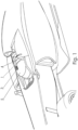
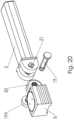
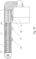
- Fig. 1 depicts a section of a formula car comprising the head and neck support and protection device according to the present invention.
- the head and neck support and protection device comprises an arm 1, having a slidably-mounted element 2 for releasably (preferably) connecting it to a helmet clip 3.
- the slidably-mounted element 2 may slide on or within the arm 1 depending on the selected embodiment. In a preferred embodiment of the device, the slidably-mounted element 2 slides within the arm 1, in a hollow portion adapted for this purpose.
- the helmet clip 3 is configured to engage a helmet pin 22 (shown in the remaining drawings), preferably being releasably fixed to a helmet 5.
- the helmet clip 3 depending on its embodiment, allows for left/right rotational head movement or full movement as naturally allowed by the wearer's neck.
- the helmet clip 3 has a quick release system, activated when pulled up, which at the same time may not accidentally release while driving.
- a resistance block 4 fixed to the chassis, forming a support for the arm 1 during vertical movements (towards the bottom of the vehicle) of a helmet 5 clipped to the helmet clip 3.
- the arm 1 In its closed position, when the slidably-mounted element 2 engages the helmet clip 3, the arm 1 preferably rests on the block 4 (or is relatively close to it).
- the arm 1 is preferably spaced by less than 1 cm from the block 4. In case of an impact from the top, the arm 1 will be blocked by the resistance block 4.
- the resistance block 4 therefore, disallows excessive movement of the helmet 5, attached to the device according to the present invention, downwards beyond natural movement range of a driver's head.
- injuries arising from pushing one's head downwards, while being sited are hereby addressed.
- the natural movement range obviously depends on the particular driver and may be adjusted.
- the arm 1 may comprise a mounting element (e.g. opening) 6 for receiving a carrying shaft 7 (shown in Fig. 2 ) in order to form a pivotable connection.
- a mounting element e.g. opening
- the arm 1 is rotatably/pivotably mounted to a support (be it the resistance block 4 or the formula car chassis).
- the arm 1 is positioned in the middle of the carrying shaft 7 (shown in Fig. 2 ).
- the rotatable/pivotable mount allows for the arm 1 to move away from the helmet, when the helmet clip 3 is disengaged, in order to facilitate easier positioning for the driver.
- the arm 1 has the helmet clip 3 at its end opposite to the pivotable mount.
- the slidably-mounted element 2 and the resistance block 4 are made from titanium, graphene, carbon fiber or similar.
- Fig. 1A the head and neck support and protection device, according to the present invention, is shown in its opened form, ready to mount a helmet 5 worn by a driver.
- Fig. 2 shows an exploded view of the head and neck support and protection device according to the present invention.
- the arm 1 (preferably L-shaped or J-shaped or S-shaped or Z-shaped or Y-shaped or the like) is preferably positioned such that its longer section extends towards the helmet 5 while its shorter section extends towards the bottom of the vehicle.
- the shape of the arm 1 mainly depends on the shape of the chassis and available space.
- the head and neck support and protection device may have its shape adapted to the size and shape of the helmet 5 as well as the shape of the chassis in dependence with the constructional requirements.
- the arm 1 may comprise a mounting element 6, 8 for receiving the carrying shaft 7.
- the mounting element may be an opening 6, positioned in an axis perpendicular to the length of the arm 1, the opening 6 being positioned at the far end of the shorter section of the arm 1.
- the carrying shaft 7 may comprise a lengthwise groove 9, while there may be present a spring element 10 between the two arms 8.
- the spring element 10 has a bent section 10A that fits the lengthwise groove 9.
- the spring element 10 partly surrounds the carrying shaft 7 (preferably to the extent allowed by the hollow section in the mounting element) while the other end 10B of the spring element 10 adheres, with its flat surface, to the arm 1 between the two arms 8 as shown in Fig. 2 .
- the flat surface acts like a spring and neutralizes the weight of the helmet and the device itself. Owing to that, the helmet 5 may be heavier and thereby safer since the driver will not feel the extra weight.
- the carrying shaft 7 may be connected to the chassis so that it is positioned parallel to the left-right axis of the vehicle.
- the carrying shaft 7 may comprise, preferably at its ends, threaded openings 7B, in which there may be positioned threaded mandrels 11, preferably comprising nests for an allen key 12.
- threaded mandrels 11 are mounted to threaded elements 13, being preferably inner-threaded bushes, fixedly mounted to a chassis of a vehicle.
- helical springs 14 of the carrying shaft 7 On the carrying shaft 7, between the arm 1 and each of the threaded mandrels 11, there are preferably positioned helical springs 14 of the carrying shaft 7.
- the helical springs 14 prevent excessive movement of the helmet 5 while taking corners (due to high centrifugal force) as well as during impacts into the helmet 5 from the left/right side. At the same time, the helical springs 14 allow some movements, which feels more comfortable.
- the slidably-mounted element 2 comprises a lengthwise groove 15 (preferably at a side facing downwards) while the arm 1 comprises, in its longer section, at least one opening for receiving a limiter 16 for limiting movement of the slidably-mounted element 2 within the arm 1.
- the limiter 16 may be a screw, preferably made from steel, which moves in the lengthwise groove 15.
- the limiter 16 limits the length, by which the slidably-mounted element 2 may pull out from the arm 1.
- a protective pin 17 for example a screw made from a soft metal or plastic (depending on the requirements, the protective pin 17 must be cut in case of a force equal or above 7 g).
- the protective pin 17 is cut (by a force acting on the slidably-mounted element 2 wherein the force is a result of a crash).
- a friction reducing agent preferably a suitable lubricant or a Teflon layer.
- the end of the slidably-mounted element 2, protruding from the arm 1, is in this embodiment releasably connectible to the helmet clip 3.
- the connection is a bolt 19 connecting suitable elements 20, 21 of the slidably-mounted element 2 and the helmet clip 3.
- the bolt is preferably inserted perpendicularly to the axis of the longer section of the arm 1.
- the slidably-mounted element 2 comprises an opening 21 (preferably in a suitable ear mount with an opening positioned perpendicularly to the axis of the longer section of the arm 1) for receiving the bolt 19 while also the helmet clip 3 comprises a similar opening 20 (preferably in a suitable ear mount with an opening positioned perpendicularly to the axis of the longer section of the arm 1) for receiving the bolt 19, as shown in Fig. 2 .
- the bolt 19 positioned in the openings 20, 21 will connect the helmet clip 3 and the slidably-mounted element 2 once a nut 19A is fixed on the bolt 19.
- other connecting means than a nut 19A may be applied as will be evident to one skilled in the art.
- connection between the slidably-mounted element 2 and the helmet clip 3 may be fixed, as shown in Fig. 2 , or pivotable as shown later with reference to Fig. 20 and Fig. 21 .
- the helmet clip 3 allows for connecting a helmet pin 22 and has a hollow portion extending throughout its height 3A (shown in more details in its cross-section shown in Fig. 8 ).
- the helmet clip 3 comprises a head 23 having a rotation limiter of the helmet pin 22, a helical spring 25, blocking balls 26, the helmet pin 22, preferably comprising a circumferential groove 27 for receiving the blocking balls 26, and a clamp ring 28 comprising a grip 29 of the clamp ring 28.
- the helical spring 25 is mounted on the head 23 (adhering to its external side walls). Next, the blocking balls 26 are input into the cavities (present at its circumference as shown in Fig. 2 ) in the head 23. The head 23 is positioned, from the top via the respective opening, in the helmet clip 3. The helical spring 25 holds the blocking balls 26, while the clamp ring 28 keeps all these elements in the helmet clip 3, until release.
- the helmet pin 22 comprises a delimiting protrusion 30 at its top section, engaging a rotation limiter (elements 30 and 24 as shown in more details in Fig. 7 ) of the helmet pin 22, which results in limiting left-right, rotational, head movement of the driver.
- the hollow portion 3A extending throughout the height of the helmet clip 3, may be preferably covered with a corresponding protective cap 31.
- the hollow portion 3A of the helmet clip 3 may only be a cavity for receiving elements 23-29.
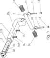
- Fig. 3 presents an exploded view, from the bottom, of the head and neck support device.
- the arm 1 has, at its longer section, at least one threaded opening 16A allowing for adjusting a length of movement of the slidably-mounted element 2 depending, in which threaded opening a limiter 16 is screwed in.
- the protective pin 17, positioned in a blocking opening in the arm 1 (herein the blocking opening is positioned at the bottom of the longer portion of the arm 1), is also positioned at the same time in the respective opening 17B in the slidably-mounted element 2.
- the slidably-mounted element 2 is configured to slide out of the arm 1, in a controlled manner, when conditions indicating a crash have been met.
- a variant of the carrying shaft 7, shown in Fig. 3 has its ends positioned in bushes fixed to the threaded mandrels 11, which are fixed with their far ends to the threaded elements 13, being preferably inner-threaded bushes, fixedly mounted to a chassis of a vehicle.
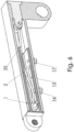
- Fig. 4 depicts a lengthwise cross-section of the arm with a helical spring 33 inside it.
- the helical spring 33 extends lengthwise, inside the slidably-mounted element 2 and the longer section of the arm 1.
- One of the ends of the helical spring 33 may be fixedly mounted to the arm 1 while the other end may be fixedly mounted to the slidably-mounted element 2 in proximity to the opening 21.
- the function of the helical spring 33 is to restrain movement of the slidably-mounted element 2.
- Fig. 5 depicts a lengthwise cross-section of the arm with a damper.
- the function of the damper 34 is to restrain movement of the slidably-mounted element 2.
- One of the ends of the damper 34 may be fixedly mounted to the arm 1 (further end from the helmet clip 3) while the other end may be fixedly mounted to the slidably-mounted element 2 in proximity to the opening 21.
- a suitable damper may be an oil damper, air dumper or a gas spring or an alternative element serving the same function.
- Fig. 6 depicts a lengthwise cross-section of the arm with an elastic cord 35.
- the function of the elastic cord 35 is to restrain movement of the slidably-mounted element 2.
- One of the ends of the elastic cord 35 may be fixedly mounted to the arm 1 (further end from the helmet clip 3) while the other end may be fixedly mounted to the slidably-mounted element 2 in proximity to the opening 21.
- the helical spring 33, the damper 34 and the elastic cord 35 are all internal braking elements configured to brake sliding of the slidably-mounted element 2 out of the arm 1.
- the slidably-mounted element 2 may, during normal driving, either (A) be substantially fixed (not movable) or (B) movable.
- the helical spring 33 and/or damper 34 keep the driver's head substantially fixed and preferably significantly limit the linear forces (in the axis of the length of the longer section of the arm 1) in a range of up to 6 - 7 g.
- the protective pin 17 is cut and the slidably-mounted element 2 moves forward (to its maximum extent allowed in order to protect from neck injury.
- the maximum extension allowed, of the slidably-mounted element 2 depends first on the driver and second on the physical structure of the formula car, but typical values will range from 5 to 10 centimeters.
- the helical spring 33 or damper 34 or the elastic cord 35 allow for some head movement, depending on driver's preferences, in a range of up to 6 - 7 g.
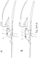
- Fig. 7 presents a section of the helmet clip 3 with a focus on the rotation limiter.
- the helmet clip 3, herein shown in an assembled version, comprises herein a hollow portion 3A (as shown in Fig. 2 ), in which there is positioned the head 23 comprising a rotation limiter 24 of the helmet pin 22 having he delimiting protrusion 30 located at its top.
- a suitable form of the rotation limiter 24 is a tooth or a protrusion or more than one thereof engaging the delimiting protrusion 30.
- the rotation limiter 24 may limit the rotation at the amount of 80 to 90 degrees to either side.
- the angle was further limited to 45 - 55 degrees to either side. This value must be adjusted to a given kind of motor sport, depending on safe values for a driver as well as requirements of a given sport.
- the head 23 is positioned inside the hollow portion 3A (as previously shown in Fig. 2 ) of the helmet clip 3, wherein the head 23 has a T-shape cross-section (vertically via its center). Around the vertical portion of the T-Shape, there is positioned the helical spring 25. Further, the head 23 comprises grooves for receiving the blocking balls 26. Additionally, the helmet pin 22 preferably comprises the circumferential groove 27 for receiving a clamp ring 28 comprising a suitable grip 29 of the clamp ring 28. Therefore, the clamp ring 28 locks the helmet pin 22 in the helmet clip 3.
- the grip 29 of the clamp ring 28 In order to attach the helmet 5 to the helmet clip 3, the grip 29 of the clamp ring 28 must be held and the helmet pin must be pulled up, while positioning the helmet pin 22 in the head 23.
- the blocking balls 26 and the clamp ring 28 block self disconnection of the helmet 5 from the helmet clip 3.
- the head 23 positioned in the helmet clip 3 may not rotate due to its protrusion (not shown on the drawing) engaging a cavity connected with the hollow portion 3A of the helmet clip 3.
- Fig. 8 shows a variant of the helmet clip having a protective cap comprising an opening.
- the embodiment of the helmet clip 3 comprises a head 23 having a rotation limiter (elements 30 and 24 as shown in more details in Fig. 7 ) of the helmet pin 22.
- the head 23 is positioned inside the hollow portion 3A (as previously shown in Fig. 2 ) of the helmet clip 3, wherein the head 23 has a T-shape cross-section (vertically via its center). Around the vertical portion of the T-Shape, there is positioned the helical spring 25. Further, the head 23 comprises grooves for receiving the blocking balls 26.
- the helmet pin 22 preferably comprises a circumferential groove 27 for receiving blocking balls 26, and a clamp ring 28.
- An opening 3B present in the top section of the helmet clip 3 is configured to receive a covering shield 31 having an opening 36.
- a difference between the embodiments shown in Fig. 7 and Fig. 8 thus lies in different actions required to attach the helmet 5 comprising a respective helmet pin 22 to the helmet clip 3.
- the embodiment of Fig. 7 one needs to hold the grip 29 of the clamp ring 28 and pull up the helmet clip 3 thereby positioning the helmet pin 22 in the head 23.
- Fig. 8 embodiment one needs to hold the head 23, with a finger inserted via the opening 36, and pull up the helmet clip 3.
- Fig. 9 depicts a variant of the helmet clip comprising a spherical member 37 having two protrusions 41 and a full recess 42 in the helmet clip 3.
- the spherical member 37 is located at the top of the helmet pin 22 and is configured to engage a hollow portion 42 of the helmet clip 3.
- the helmet pin 22 has, under the spherical member 37, a circumferential recess 38 configured to receive a spring clip 39.
- the helmet clip 3 has a cut out portion 40 for receiving the spring clip 39 so that the helmet pin 22 inserted inside the hollow portion 42 may be locked within. Once locked, the helmet pin may be disengaged by pulling out the spring clip 39 using its grip portion.
- the spherical member 37 may further comprise two protrusions 41, preferably opposite each other, configured to engage the hollow portion 42 of the helmet clip 3 and to be inserted via guiding sections 43 present in the helmet clip 3.
- the embodiment of the helmet clip 3, shown in Fig. 9 allows for freedom of movement of driver's head within a safe range.
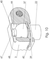
- Fig. 10 presents a variant of the helmet clip comprising a spherical member 37 having two protrusions and a partial recess in the helmet clip 3.
- the spherical member 37 has a top member 47 in a form of a disc having two opposite protrusions 48.
- the helmet clip 3 has a partial cavity 44, in which the top member 47 is positioned, allowing a horizontal movement of the driver's head.
- the two opposite protrusions 48 restrict a rotational movement of the helmet pin 22 having the top member 47.
- a difference between the full recess 42 in the helmet clip 3 ( Fig. 9 ) and the partial recess in the helmet clip 3 ( Fig. 10 ) is that the partial recess is configured to allow for a natural, horizontal movement (looking left/right) of a helmet 5 only while the full recess allows helmet 5 movements in all axes but restricted to natural head movement range of angles (for example by a use of appropriate protrusions).
- the embodiment of Fig. 10 in particular a connection between the helmet clip 3 and the helmet pin 22, is configured to facilitate a nodding movement.
- the helmet pin 22 has, under the spherical member 37, the circumferential recess 38 (as shown in Fig. 9 ) configured to receive a spring clip 39.
- the helmet clip 3 has a cut out portion 40 for receiving the spring clip 39 so that the helmet pin 22 inserted inside the hollow portion 42 may be locked within. Once locked, the helmet pin may be disengaged by pulling out the spring clip 39 using its grip portion.
- the embodiment of the helmet clip 3, shown in Fig. 10 allows for freedom of movement of driver's head within a safe range.
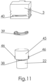
- Fig. 11 shows an exploded view of the helmet clip with the helmet pin 22 having a cylindrically-shaped portion 45.
- the cylindrically-shaped portion 45 is located at the top of the helmet pin 22 and comprises two, preferably opposite, protrusions 46 for engaging two respective cavities present in the helmet clip 3 (not shown on the drawing).
- the protrusions 46 and the cavities limit the rotational movement of the helmet pin 22 having the cylindrically-shaped portion 45.
- Fig. 12 presents an exploded view of the helmet clip 3 with the helmet pin 22 having a cylindrically-shaped portion 45, a disc top member 47 and two opposite protrusions 48 extending on the disc (as explained above, the number of such protrusions may vary).
- the disc top member 47 has preferably a lower diameter than the cylindrically-shaped portion 45.
- the helmet clip 3 comprises, at its top, an opening with recesses 49 for receiving the disc top member 47 and the two opposite protrusions 48 extending on the disc top member 47.
- the protrusions 48 and the recesses once engaged, limit the rotational movements of the helmet pin 22 having the cylindrically-shaped portion 45 with the disc top member 47.
- the helmet pin 22 has, under the cylindrically-shaped portion 45, the circumferential recess 38 configured to receive a spring clip 39.
- the helmet clip 3 has a cut out portion 40 for receiving the spring clip 39 so that the helmet pin 22, inserted inside the hollow portion 42, may be locked within.
- the helmet pin 22 may be disengaged, from the helmet clip 3, by pulling out the spring clip 39, using its grip portion, from the cut out portion 40 and with a rotational movement pull the arm 1 over driver's head.
- the arm 1 will rotate (pivot) on the carrying shaft 7.
- Fig. 13 depicts an exploded view of the helmet clip 3 with the helmet pin 22 having a cylindrically-shaped portion 45 and a bearing 50.
- the bearing 50 is positioned within the hollow portion 42 of the helmet clip 3, which is configured to receive a disc top member 47 of the helmet pin 22.
- the disc top member 47 has preferably a lower diameter than the cylindrically-shaped portion 45.
- the cylindrically-shaped portion 45 present underneath the disc top member 47, has two, preferably opposite, protrusions 46 for engaging two respective cavities present within in the helmet clip 3 (not shown on the drawing).
- the protrusions 46 and the respective cavities limit the rotational movement of the helmet pin 22 having the cylindrically-shaped portion 45 and the disc top member 47.
- Fig. 14 shows an exploded view of the helmet clip 3 with the respective helmet pin 22 having a disc top member 47, the bearing and an opening for receiving a cap.
- a rod-like stopper 51 instead of the spring clip 39 there is employed a rod-like stopper 51.
- the disc top member 47 comprises a cavity 54 for receiving a portion of the rod-like stopper 51, wherein further the bearing 50 has, in its bottom portion, a horizontal through hole 53 (in a wall of its bottom section), matching the cavity 54. Therefore, the rod-like stopper 51, inserted via the cut out portion 40, passes via the horizontal through hole 53 and enters the cavity 54 thereby blocking the helmet pin 22 in the helmet clip 3.
- the cut out portion 40 limits a rotational movement of the helmet pin 22 and allows for freedom of movement of driver's head within a safe range.
- the rod-like stopper 51 may have a wider ending or a bent portion 51A, configured to operate as a grip portion, as shown in Fig. 13 .
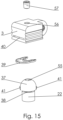
- Fig. 15 shows an exploded view of the helmet clip 3 with the helmet pin 22 having a spherically-shaped portion 37 and an opening 55, in the top section of the spherical portion 37, for receiving a locking member 57.
- the opening 55 preferably has a horizontal diameter and receives the locking member 57 in a vertical direction (axis).
- the spherically-shaped portion 37 further comprises at least one protrusion (preferably two, opposite each other) 41 for engaging respective at least one cavity present in the helmet clip 3 (not shown on the drawing).
- the helmet clip 3 has in its top portion a substantially center opening 56 for receiving the locking member 57, which also engages the opening 55, in the top of the spherical portion 37.
- the helmet pin 22 has, under the spherically-shaped portion 37, the circumferential recess 38 configured to receive a spring clip 39.
- the helmet clip 3 has a cut out portion 40 for receiving the spring clip 39 so that the helmet pin 22, inserted inside the helmet clip 3, may be locked within.
- the helmet pin 22 may be disengaged, from the helmet clip 3, by pulling out the spring clip 39, using its grip portion, from the cut out portion 40 and with a rotational movement pull the arm 1 over driver's head.
- the arm 1 will rotate (pivot) on the carrying shaft 7.
- Fig. 16 presents a cross-section of the helmet clip 3 having an inserted helmet pin 22 comprising the spherically-shaped portion 37 with the disc top member comprising two opposite protrusions 48.
- Two opposite protrusions 48 are preferred due to stability and equal distribution of forces, but there may be embodiments where the protrusions 48 are not opposite each other and where there is only one or more than two protrusions serving the same purpose.
- the helmet clip 3 comprises an opening 49 (preferably having a horizontal diameter) with cavities for receiving the corresponding two opposite protrusions 48, which also act as rotation limiters of the helmet pin 22.
- the helmet pin 22 has, under the spherical member 47, the circumferential recess 38 (as previously shown in Fig. 15 ) configured to receive a spring clip 39.
- the helmet clip 3 has a cut out portion 40 for receiving the spring clip 39 so that the helmet pin 22, inserted inside the hollow portion of the helmet pin 3, may be locked within.
- the helmet pin 3 may be disengaged by pulling out the spring clip 39, using its grip portion, from the cut out portion 40 and with a rotational movement pull the arm 1 over driver's head.
- the arm 1 will rotate (pivot) on the carrying shaft 7.
- Fig. 17 depicts the helmet pin 22 mounted on the helmet 5.
- the helmet pin 22 comprises the circumferential groove 27, for receiving a clamp ring 28, and has the delimiting protrusion 30 located at its top.
- the element pin 22 may be mounted on the helmet 5 using any techniques known in the art. In this embodiment the connection is not releasable.
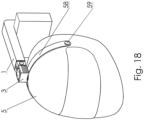
- Fig. 18 shows an embodiment of the present invention in which the helmet pin 22 is connected to a clamp 58 pivotably mounted on the helmet 5.
- This embodiment provides improved stability of the helmet 5 and may be releasable depending on the kind of the connection 59 of the clamp 58 to the helmet 5.
- the connection 59 is made with rivets on left and right side of the helmet 5.
- Fig. 19 presents an embodiment of the present invention in which the helmet pin 22 is releasably fixed 61 to a guide 60 connected to the helmet.
- a slider element 61 is fixed to the guide 60. This embodiment provides improved stability of the helmet 5 and is releasable.
- Fig. 20 depicts the helmet clip 3 and the slidably-mounted element 2 in an embodiment comprising a four-teeth bolt 19. Additionally, the opening(s) 21 in the slidably-mounted element 2 also are corresponding four-teeth openings for receiving the four-teeth bolt 19. Preferably, the width of the teeth of the opening(s) 21 is greater than the width of the teeth of the bolt 19.
- the ear mount of the helmet clip 3 has its opening 20 with a plurality of teeth, e.g. 16. This arrangement allows for more flexibility when a nodding movement is concerned.
- Fig. 21 shows the helmet clip 3 and the slidably-mounted element 2 in an embodiment comprising a protrusion 63 in a seat, of the helmet clip 3, located between the two ears comprising respective openings 21 being configured to receive the bolt 19.
- the ear of the helmet clip 3 comprising the opening 20 also has a recess 62 corresponding to the protrusion 63 so that it may be engaged in an assembled state. As previously explained the bolt is received perpendicularly to the length of the longer section of the arm 1.
- Fig. 22 presents the arm 1 assembled on the carrying shaft 7 as previously shown in Fig. 2 as disassembled elements view.
- the carrying shaft 7 comprises a groove 9, in which one end of the spring element 10 is positioned.
- the spring element 10 partly surrounds the carrying shaft 7 (preferably to the extent allowed by the hollow section in the mounting element) while the other end 10B of the spring element 10 adheres, with its flat surface, to the arm 1 between the two arms 8 as shown in Fig. 2 .
- the flat surface acts like a spring thereby achieving the helmet's weight neutralizing function as explained with reference to Fig. 2 .
- Fig. 23 depicts a back view of the arm 1 assembled on the carrying shaft 7 wherein the helical springs 14 are fixed (for example anchored) to the arm 1 with their respective ends directed towards the arm 1.
- the other ends of the helical springs may be releasably fixed to the carrying shaft 7.
- other ends of the helical springs may be releasably fixed to respective left and right bushes 32 configured to receive the ends of the carrying shaft 7.
- the carrying shaft 7 does not comprise, at its ends, the threaded openings 7B, in which there may be positioned the threaded mandrels 11, as shown in Fig. 2 . Instead, the threaded mandrels 11 are rather fixed to the left and right bushes 32 respectively.
- Fig. 24 shows a bottom view of the arm 1 assembled on the carrying shaft 7 wherein the carrying shaft has energy absorbing elements 64 mounted thereon instead of the helical springs 14.
- the energy absorbing elements 64 may be made from a CONFOR foam.
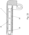
- Fig. 25 presents a lengthwise cross section of the arm 1 comprising bearings elements 18.
- the bearings elements 18 are preferably located on all four sides of the hollow portion of the longer section of the arm 1.
- a friction reducing agent preferably a suitable lubricant or a Teflon layer.
- Fig. 26 depicts a view of the arm 1 with a carrying shaft 7 being mounted in a bearing 65.
- the bearing 65 is mounted in the opening 6, positioned in an axis perpendicular to the length of the arm 1.
- the bearing 65 facilitates a more smooth pivot around the carrying shaft 7.
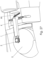
- Fig. 27 presents a section of a formula car having the arm 1 connected to its chassis by means of an additional spring 66.
- the function of the spring is to allow easier release of the helmet clip 3 and keeping the opened arm 1 above the helmet 5 to avoid hitting the helmet pin 22 with an opened helmet clip 3. Further, the spring 66 compensates the weight of the device and the attached helmet 5, which as previously described allows for more comfort and makes it possible to use heavier and safer helmets 5.
- Fig. 28 shows a section of a formula car having the arm 1 connected to its chassis wherein the arm 1 has an additional counterweight 67 with respect to vertical movements of the helmet 5.
- the purpose of the counterweight 67 is the same as in case of the spring 66.
- element 281 may act also as a blocking block for the device according to the present invention, in case the helmet is pushed downwards.
- Fig. 29 depicts the arm 1 having an additional damping element 68 engaging the resistance block 4.
- Said damping element 68 decreases the pressure of the arm on the driver's head and eliminates rapid impacts of the arm 1 on the resistance block 4 in case of a collision of the helmet 5 with a flying object or hitting a safety fence by the formula car.
- Fig. 30 presents an embodiment of the arm 1 having an I-shape.
- Atypical length of the arm 1 is first determined by the slidably-mounted element 2 and secondly by the construction of the formula car. Typically, the length will be greater than 10 cm but may extend beyond 20 cm. In a preferred embodiment the arm 1 has a length between 10 cm and 15 cm.
- the end of the arm, further away from the helmet clip 3, ends directly with an opening 6 for receiving the carrying shaft 7.
- the bolt 19 connecting suitable elements (20, 21) of the slidably-mounted element 2 and the helmet clip 3 is not present and the slidably-mounted element 2 ends directly with the helmet clip. Such an embodiment further reduces the weight of the device.
- Fig. 31 shows the device according to the present invention mounted on a shell 69 surrounding a driver's helmet 5 (when a driver takes a driving position) whereas the shell 69 is fixed to the chassis of the vehicle. Further, the arm 1 comprises a protective element configured to protect the helmet clip 3 from damage.
- Fig. 32 depicts the surrounding shell 69 comprising a resistance block 71.
- the resistance block 71 is the same as the resistance block 4 with a difference lying in the location of its mounting.
- the resistance block 4 is mounted on the chassis of the formula car while the resistance block 71 is mounted on the surrounding shell 69. In both cases the resistance block 4, 71 is configured to transfer energy into the chassis when the arm 1 hits the resistance block 4, 71 from above.
- a friction reducing agent such as a suitable lubricant or a Teflon layer.
- the improved and cost effective Head and Neck Support And Protection device also protects the head from impacts from the top as well as provides the support function.
- the present invention provides an improved protection by appropriately transferring forces from the elements impacting the helmet into the described device and further to the chassis of the vehicle.
- Fig. 33 presents a process of an impact of a wheel into the system according to the present invention.
- the driver's helmet may only slightly move left-right as allowed by rotation limiters (within a safe range) or may move slightly downwards (for example in case of an embodiment shown in Fig. 29 (within a safe range).
- the slidably-mounted element 2 at the foremost end of which there is mounted the helmet clip 3 attached to a helmet 5, moves forward (in a linear fashion), together with the body of a driver in order to prevent injuries to the neck.
- the helical spring 14 will decrease forces acting on the head and will protect from injuries in such cases.
- Figs. 34A-B show a process of reaction of the system according to the present invention, to an impact into a safety fence.
- the slidably-mounted element 2 has extended, to its maximum allowed range, thus preventing injuries to the neck.
- Figs. 35A-C depict a process of installing and attaching a helmet to the system according to the present invention. This series of steps show an embodiment of the present invention presented with relation to Fig. 7 .
- Fig. 35A after a driver has taken a seat in the formula car, the device remains open (as shown in Fig. 1A ) and a person (be it the driver or a support team member) holds the grip 29 of the clamp ring 28 with the index finger 351.
- Fig. 35B With the index finger 352 of the other hand and the thumb 353 one pulls the helmet clip 3 up, which results in loosening the blocking balls 26, present in respective openings in the head 23, that fall into the recess (see helmet clip 3 in Fig. 8 ) in the helmet clip 3.
- the connection operates as a so called quick release system.
- the arm 1 is pulled downwards connecting the helmet clip 3 to the helmet pin 22 still holding the helmet clip 3 and the grip 29 as previously shown. Once the helmet clip 3 engages the helmet pin 22 the fingers, holding the respective elements, may be released. Then the blocking balls 26 are locked.
- Fig. 36 shows an embodiment of a helmet 5 having a flattened top portion 5A, which allows locating the helmet pin 22 and consequently the arm 1 lower (even over 20 mm) than at typical rounded helmets, thereby lowering the mass center of the whole system.
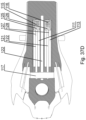
- Figs. 37A , 37B , 37C show another embodiment of the head and neck support device in an assembled view, an exploded view from the top and bottom, respectively.
- Fig. 37D shows a cross-section of the arm.
- the arm 101 may be T-shaped, i.e. it may comprise three portions 101A, 101B, 101C forming the legs of the letter T. It has a first portion 101A to which a slidably-mounted element 102 is connected, a second portion 101B to be fixed to a carrying shaft 107 and a third portion 101C that rests on a resistance block 4 (that absorbs the energy of the impact, e.g. of a wheel to the helmet).
- the actuator 181 connected to the third portion 101C of the arm 101, is used to effect lifting the arm 101 to an open position (as shown in Fig. 37A ) to enable the driver entering and exiting the vehicle, by rotating the arm 101 around the pivot point defined by the carrying shaft 107.
- the carrying shaft 107 and the actuator 181 are fixed to the vehicle chassis.
- the actuator 181 is also used to neutralize the weight of the driver's head, the helmet and the overall system weight to limit their load acting on the driver's neck.
- the openings 112, 114 are to accommodate longitudinal shafts 122, 124 that act as guiding rails for a slidably-mounted element 102. Alternatively, a single guiding opening and a single guiding rail may be used.
- the longitudinal shafts 122, 124 also provide protective function when, during extension of the slidably-mounted element 102, something hits the helmet - in that case the impact force is absorbed by the longitudinal shafts 122, 124 (in addition to the piston rods 121, 123).
- the openings 111, 113 function as cylinders of an actuator, in which a piston rod 121, 123 terminated with a piston 125, 126 is movable.
- Such actuators limit the movement of the driver's head along the longitudinal axis of the arm 101, i.e. the longitudinal axis of the vehicle between the vehicle front and back.
- the openings 111, 113 may have springs 115, 116 mounted in their end portions to dampen the movement of the pistons 125, 126 towards the back of the vehicle.
- the springs 115, 116 along with the absorbing element 117, dampen the movement of the slidably-mounted element 102 during the backward movement and during a hit from the front side to the helmet (e.g. by a wheel), or when the vehicle is hit at the back by another vehicle.
- the piston rods 121, 123 may have transverse through openings 127, 128 positioned in front of the pistons 125, 126 to release the high pressure formed during forward movement of the pistons 125, 126.
- An absorbing element 117 (having through-holes through which the rods 121-124 may move) is fixed to the end of the first portion 101A.
- the slidably-mounted element 102 moves forwards such that positive pressure forms in the cylinders 111, 113 between the pistons 125, 126 and the front portion of the cylinders 111, 113 and negative pressure increases between the pistons 125, 126 and the back portion of the cylinders 111, 113.
- the high positive pressure may be then at least partially released via the through openings 127, 128.
- the actuators may be configured to have, in a resting position, a neutral pressure at the back of the pistons 125, 126 (i.e. between the pistons 125, 126 and the springs 115, 116) which lowers to a negative pressure during frontal movement of the pistons 125, 126.
- the actuators may have in the resting position, a negative pressure formed at the back of the cylinders 125, 126.
- the actuators may be configured to have, in the resting position, a positive pressure formed at the front of the cylinders 125, 126, such as to limit the movement for low G forces and effect the movement only upon accident.
- the overpressure and underpressure at the front and back of the cylinders 125, 126, respectively, may be formed by gas nozzles located at the front and back of the cylinders 125, 126 (not shown for clarity of drawing).
- the head and neck supporting system comprises a head supporting tape or rope, which is mounted at one end to a vehicle chassis (as shown in various embodiments on Figs. 38A-38J ) and at the other end to the slidably-mounted element of the arm of any of the previous embodiments (as shown in various embodiments on Figs. 39A-39D ), wherein the tape or rope may pass through a holder at the helmet at a position in the lower half of the helmet or it may be secured at the sides of the helmet, such as to bias the head downwards when the slidably-mounted element moves forward, or it may pass directly without being attached to the helmet (as in Fig. 38I ).
- the tape or rope may pass from the slidably-mounted element via the lower side of the arm (as shown in Fig. 38J ).
- the tape or rope moves along with the slidably-mounted element and therefore it induces rotation of the driver's head in the helmet that is in accordance with the movement of the driver's body. This limits the forces acting on the driver's neck and therefore reduces the injury to the neck.
- the movement of the driver's head sidewards may be limited, as shown in Fig. 40 , by a sidewards limiting actuator formed by the mounting element 106 and the shaft 107, wherein the mounting element 106 forms a cylinder and the shaft 107 has a centrally mounted piston 107A and its side arms 107B, 107C form piston rods.
- the side arms 107B, 107C are connected to the vehicle chassis.
- the movement of the piston 107A within the cylinder is therefore dampened by overpressures and undepressures formed at sideward movement.
- the actuator may be configured to have, in the resting position, a positive pressure formed of the cylinder, such as to limit the movement for low G forces and effect the movement only upon accident.
- the overpressure or underpressure, respectively, may be formed by gas nozzles located on the cylinder (not shown for clarity of drawing).
- the system according to the invention limits the movement of the head sideways and allows rotation of the head sideways and in the driving direction.
- Fig. 38A there is shown an embodiment of a tape 191T that is connected at a helmet holder 5H located at the back of the helmet 5.
- One end of the tape is held by a chassis holder 192A that is attached to the vehicle chassis.
- Fig. 39A the tape is shown in loose configuration.
- the tape 191T is attached to an actuator 192B that is attached to the vehicle chassis.
- the tape 191T passes through a holder 194 located under the arm (which can be applied also for other embodiments in Figs. 38A-38J and 39A-39D ).
- a rope 191R is attached to a spring 192C that is attached to the vehicle chassis.
- the tape 191T is attached to the actuator 192B, which is attached to a pretensioner 192D (which is attached to the vehicle chassis) that holds the tape 191T in a slightly tensioned configuration.
- the tape 191T is quickly tightened.
- the pretensioner 192D allows extension of the tape 191T.
- the rope 191R is attached to the spring 192C, which is attached to the pretensioner 192D (which is attached to the vehicle chassis) that holds the tension of the rope 191R.
- a pair of ropes 191 R2 extends at both sides of the helmet 5 and passes via yokes 5Y and is attached to the holder 192A attached to the vehicle chassis.
- a tape 191T is guided from the slidably-mounted element 102, under the arm 101, to the vehicle chassis (e.g. via an actuator 192B and a pretensioner 192D).
- a rope 191R may be used instead of the tape 191T and the ends of the tape or rope may be attached also to the vehicle chassis by other means 192A, 192C, such as shown in the embodiments of Figs. 38B-38F .
- a first tape 191T1 is guided from the slidably-mounted element 102, via a holder 194 at the bottom of the arm, to an actuator 192B and a pretensioner 192D connected to the vehicle chassis.
- a second tape 191T2 is guided from the holder 194 to the actuator 192B and the pretensioner 192D connected to the vehicle chassis.
- the support 194 prevents the tapes from rubbing against the helmet.
- the helmet holder 5H or holder 194 shall be positioned above the point at which the end of the tape or rope is connected to the vehicle chassis.
- the device may further comprise an additional cylinder having piston rods 195A, 195B extending from it sidewards and slightly shorter than the ends of the piston rods 107B, 107C, such that when the device is moved, these rods 195A, 195B hit the sides of the chassis, thereby enhancing the action of the piston rods 107B, 107C for limiting the movement of the structure sidewards.
- two separate cylinders can be used.
- Fig. 39A shows an embodiment of mounting the head supporting tape to the arm, in an attached and detached configuration.
- the tape 191T has mounting holes 193A via which it is secured to mounting hooks 193B near the helmet clip 103.
- Fig. 39B shows an embodiment of mounting the head supporting tape 191T having a metal or metalized end portion 193C to magnets 193D near the helmet clip 103.
- the tape is guided via a holder 194 under the arm 101 such as to avoid contact between the tape and the helmet.
- holder 194 can be used in a similar manner in the other embodiments as well.
- Fig. 39C shows an embodiment of mounting the head supporting tape 191T to guides 193E near the helmet clip 103.
- Fig. 39D shows an embodiment of mounting the head supporting rope 191R to guides 193E near the helmet clip 103.
- the elements shown are configured such that when the driver enters the vehicle, the head supporting tape or rope is mounted to the arm 101 by the support personnel.
- the elements are easily detachable and do not hamper the exit procedure - they either slide out easily or can be easily detached by the driver.
- the system according to the present invention serves as protection from impacts into the helmet, limits head movements (e.g. in case of taking sharp turns with relatively high g values) as well as protects in case of impacts of the vehicle into for example a safety fence. Therefore, the invention provides a useful, concrete and tangible result.
Description
- A HANS device (Head and Neck Support device), also known as a head restraint, is a safety item compulsory in many car racing sports. It reduces the likelihood of head and/or neck injuries, such as a basilar skull fracture, in the event of a crash (be it hitting another vehicle or a safety fence).
- Prior art defines that the purpose of the HANS device is to keep the head from whipping forwards and backwards in a crash, (while also preventing excessive rotational movement, as secondary protection) without otherwise restricting movement of the neck.
- In other words, the HANS allows the wearer to move their head as normal, but prevents/restricts head movements during a crash that would otherwise exceed the normal articulation range of the skeletal/muscular system and cause severe injury. In any kind of crash, the person's body, which isn't protected, is decelerated by the seat belt with the head maintaining velocity until it is decelerated by the neck.
- The HANS device maintains the relative position of the head to the body, in addition to transferring energy to the much stronger chest, torso, shoulder, seatbelts, and seat as the head is decelerated (source: Wikipedia).
- The HANS device is applicable in all motor sports, especially those where vehicles or boats do not comprise typical roof sections. Examples of use include formula racing cars, airplanes or speed boats where the head and the neck are exposed to high risks.
- A driver, of a racing car, wears a special helmet connected to the HANS system. The head and neck protection, of the driver, is a result of restraining forces that are present especially during a crash or when the helmet is hit by a flying object (for example such objects are typically parts of tires or parts of chassis of other cars involved in a prior crash).
- Presently, for such protective purposes, there are used (a) elastic sections attached to a chassis in the vicinity of a helmet, (b) raised side sections of the chassis in order to cover the helmet on its sides, (c) a foam-shell, collar-like device formed with a high collar, a left leg unit and a right leg unit connected to the high collar so that a U-shape is obtained or a set of nylon or steel cords connected to the helmet and configured to transfer a given force to a harness worn on driver's shoulders.
- A prior art publication of
FR2720988 - The solution of
FR2720988 - Further, the device of
FR2720988 - A prior art publication of
WO98/13232 - The solution of
WO98/13232 - Another prior art publication of
US2015/0020293 entitled "Head and Neck Support Device" discloses a head and neck support device for an occupant of a vehicle with a shoulder harness over the shoulders of the occupant and a helmet on a head of the occupant. The head and neck support device having a yoke, a tether, and at least one sleeve member, which has a cavity defined therethrough. The tether is configured to slide through the sleeve member cavity for a defined distance, which allows the occupant a greater range of side-to-side rotary head mobility. - The solution, according to the
US2015/0020293 , has a disadvantage that it does not protect a driver in case of a hit, of the helmet, by a part of another vehicle or in case of a hit into a safety fence. - A further prior art of
DE4418179 entitled "Device protecting racing driver helmet from side force" discloses a device that protects a helmet of the driver of a racing vehicle against inertia forces acting on the driver in a direction essentially perpendicular to the direction of travel. The unit has a first lever which is fixed to the vehicle body and able to pivot, and also has releasable connection to the helmet. An equal and opposite weight to the accelerator inertia force is applied to the drivers helmet via the lever linkage. The lever linkage consists of a first and second lever. - A drawback of this solution of a lack of protection in case of a hit, of the helmet, by a part of another vehicle (any flying object in general) or in case of a hit into a safety fence. The solution does not restrain head movement around the vertical axis, as a result of which there may occur breaking of a spinal cord, in particular the neck section.
- A prior art
publication WO2017/074206 , that corresponds to the preamble ofclaim 1, discloses a head and neck support and protection device comprising an arm, pivotably mounted to a support, comprising a helmet clip, at its end opposite to the pivotable mount, configured to engage a helmet pin; a resistance block configured to transfer energy into a chassis when the arm hits the resistance block; wherein the arm has a slidably-mounted element for connecting it to the helmet clip; whereas the slidably-mounted element is configured to slide out of the arm, in a controlled manner, when conditions indicating a crash have been met. - As shown above, current solutions do not sufficiently protect in case of a hit, of a helmet, by external elements like flying objects such as a part of another vehicle and thus do not provide sufficient safety to the head, the neck and the spine.
- Known solutions protect mainly the neck, which may experience injury due to an inert movement of the head during a crash.
- The helmet itself only partially protects the head while the neck is exposed to great forces, especially in case of impact from the top, that may cause severe spine injury and in some cases death.
- The aim of the development of the present invention is an improved and cost effective Head and Neck Support And Protection device, which would also protect the head from impacts from the top as well as allow for rapid leaving of the vehicle, for example during a fire.
- The present invention relates to a head and neck support and protection device for a driver of a vehicle according to the appended claims.
- These and other objects of the invention presented herein, are accomplished by providing the Head and Neck Support And Protection device. Further details and features of the present invention, its nature and various advantages will become more apparent from the following detailed description of the preferred embodiments shown in a drawing, in which:
-
Figs. 1 and1A depict a section of a formula car comprising the head and neck support and protection device according to the present invention; -
Fig. 2 shows an exploded view of the head and neck support device according to the present invention; -
Fig. 3 presents an exploded view, from the bottom, of the head and neck support device; -
Fig. 4 depicts a lengthwise cross-section of the arm with a helical spring; -
Fig. 5 depicts a lengthwise cross-section of the arm with a damper; -
Fig. 6 depicts a lengthwise cross-section of the arm with an elastic cord; -
Fig. 7 presents a section of the helmet clip with a focus on the rotation limiter; -
Fig. 8 shows a variant of the helmet clip having a protective cap comprising an opening; -
Fig. 9 depicts a variant of the helmet clip comprising a spherical member having two protrusions and a full recess in the helmet clip; -
Fig. 10 presents a variant of the helmet clip comprising a spherical member having two protrusions and a partial recess in the helmet clip; -
Fig. 11 shows an exploded view of the helmet clip with the helmet pin having a cylindrically-shaped portion; -
Fig. 12 presents an exploded view of the helmet clip with the helmet pin having a cylindrically-shaped portion, a disc top member and two opposite protrusions; -
Fig. 13 depicts an exploded view of the helmet clip with the helmet pin having a cylindrically-shaped portion and a bearing; -
Fig. 14 shows an exploded view of the helmet clip with the helmet pin having a cylindrically-shaped portion, the bearing and an opening for receiving a cap; -
Fig. 15 shows an exploded view of the helmet clip with the helmet pin having a spherically-shaped portion and an opening, in the spherical portion, for receiving a locking member; -
Fig. 16 presents a cross-section of the helmet clip having an inserted helmet pin comprising the spherically-shaped portion with the disc top member and two opposite protrusions; -
Fig. 17 depicts the helmet pin mounted on the helmet; -
Fig. 18 shows an embodiment of the present invention in which the helmet pin is connected to a clamp pivotably mounted on the helmet; -
Fig. 19 presents an embodiment of the present invention in which the helmet pin is releasably fixed to a guide connected to the helmet; -
Fig. 20 depicts the helmet clip and the slidably-mounted element in an embodiment comprising a four-teeth bolt; -
Fig. 21 shows the helmet clip and the slidably-mounted element in an embodiment comprising a protrusion in a seat of the helmet clip; -
Fig. 22 presents the arm assembled on the carrying shaft; -
Fig. 23 depicts a back view of the arm assembled on the carrying shaft wherein the helical springs are fixed to the arm with their respective ends directed towards the arm; -
Fig. 24 shows a bottom view of the arm assembled on the carrying shaft wherein the carrying shaft has absorbing elements mounted thereon instead of the helical springs; -
Fig. 25 presents a lengthwise cross section of the arm comprising bearings; -
Fig. 26 depicts a view of the arm with a carrying shaft being mounted in a bearing; -
Fig. 27 presents a section of a formula car having the arm connected to its chassis by means of an additional spring; -
Fig. 28 shows a section of a formula car having the arm connected to its chassis wherein the arm has an additional counterweight with respect to vertical movements of the helmet; -
Fig. 29 depicts the arm having an additional damping element engaging a resistance block; -
Fig. 30 presents an embodiment of the arm having an I-shape; -
Fig. 31 shows the device according to the present invention mounted on a shell surrounding a driver's helmet whereas the shell is fixed to the chassis of the vehicle; -
Fig. 32 depicts the shell comprising the resistance block; -
Fig. 33 presents a process of an impact of a wheel into the system according to the present invention; -
Figs. 34A-B show a process of reaction of the system according to the present invention, to an impact into a safety fence; and -
Figs. 35A-C depict a process of installing and attaching a helmet to the system according to the present invention; -
Fig. 36 shows an embodiment of a helmet with a flat top; -
Fig. 37A shows an assembled view of another embodiment of the head and neck support device; -
Fig. 37B shows an exploded view of the embodiment ofFig. 37A in a view from the top; -
Fig. 37C shows an exploded view of the embodiment ofFig. 37A in a view from the bottom; -
Fig. 37D shows a cross-section of the arm. -
Fig. 38A shows an embodiment of mounting a head supporting tape or rope to the vehicle chassis;Fig. 38B shows another embodiment of mounting a head supporting tape or rope to the vehicle chassis; -
Fig. 38C shows another embodiment of mounting a head supporting tape or rope to the vehicle chassis; -
Fig. 38D shows another embodiment of mounting a head supporting tape or rope to the vehicle chassis; -
Fig. 38E shows another embodiment of mounting a head supporting tape or rope to the vehicle chassis; -
Fig. 38F shows another embodiment of mounting a head supporting tape or rope to the vehicle chassis; -
Fig. 38G shows another embodiment of mounting a head supporting tape or rope to the vehicle chassis; - Fig. 381 shows another embodiment of mounting a head supporting tape or rope to the vehicle chassis;
-
Fig. 38J shows another embodiment of mounting a head supporting tape or rope to the vehicle chassis; -
Fig. 39A shows an embodiment of mounting a head supporting tape to the arm; -
Fig. 39B shows another embodiment of mounting a head supporting tape to the arm; -
Fig. 39C shows another embodiment of mounting a head supporting tape to the arm; -
Fig. 39D shows an embodiment of mounting a head supporting rope to the arm. -
Fig. 40 shows an sideward limiting actuator for limiting the movement of the head sideways. - The embodiments presented herein refer to a formula car and all particular values of forces will be presented with reference to this motor sport. In case of other motor sports, such as airplanes or speed boats, other forces may apply and appropriate adjustments may be made.
-
Fig. 1 depicts a section of a formula car comprising the head and neck support and protection device according to the present invention. The head and neck support and protection device comprises anarm 1, having a slidably-mountedelement 2 for releasably (preferably) connecting it to ahelmet clip 3. - The slidably-mounted
element 2 may slide on or within thearm 1 depending on the selected embodiment. In a preferred embodiment of the device, the slidably-mountedelement 2 slides within thearm 1, in a hollow portion adapted for this purpose. - The
helmet clip 3 is configured to engage a helmet pin 22 (shown in the remaining drawings), preferably being releasably fixed to ahelmet 5. Thehelmet clip 3, depending on its embodiment, allows for left/right rotational head movement or full movement as naturally allowed by the wearer's neck. - Preferably, the
helmet clip 3 has a quick release system, activated when pulled up, which at the same time may not accidentally release while driving. - Under the
arm 1, there is positioned aresistance block 4, fixed to the chassis, forming a support for thearm 1 during vertical movements (towards the bottom of the vehicle) of ahelmet 5 clipped to thehelmet clip 3. In its closed position, when the slidably-mountedelement 2 engages thehelmet clip 3, thearm 1 preferably rests on the block 4 (or is relatively close to it). - In other embodiment, the
arm 1 is preferably spaced by less than 1 cm from theblock 4. In case of an impact from the top, thearm 1 will be blocked by theresistance block 4. - The
resistance block 4 therefore, disallows excessive movement of thehelmet 5, attached to the device according to the present invention, downwards beyond natural movement range of a driver's head. Thus, injuries arising from pushing one's head downwards, while being sited are hereby addressed. - The natural movement range obviously depends on the particular driver and may be adjusted.
- A further embodiment of the spacing between the
arm 1 and theresistance block 4 will be shown with reference toFig. 29 . - The
arm 1 may comprise a mounting element (e.g. opening) 6 for receiving a carrying shaft 7 (shown inFig. 2 ) in order to form a pivotable connection. Thus, thearm 1 is rotatably/pivotably mounted to a support (be it theresistance block 4 or the formula car chassis). Advantageously, thearm 1 is positioned in the middle of the carrying shaft 7 (shown inFig. 2 ). - The rotatable/pivotable mount allows for the
arm 1 to move away from the helmet, when thehelmet clip 3 is disengaged, in order to facilitate easier positioning for the driver. - As shown in
Fig. 2 , thearm 1 has thehelmet clip 3 at its end opposite to the pivotable mount. - In preferred embodiments the slidably-mounted
element 2 and theresistance block 4 are made from titanium, graphene, carbon fiber or similar. - In
Fig. 1A the head and neck support and protection device, according to the present invention, is shown in its opened form, ready to mount ahelmet 5 worn by a driver. -
Fig. 2 shows an exploded view of the head and neck support and protection device according to the present invention. The arm 1 (preferably L-shaped or J-shaped or S-shaped or Z-shaped or Y-shaped or the like) is preferably positioned such that its longer section extends towards thehelmet 5 while its shorter section extends towards the bottom of the vehicle. The shape of thearm 1 mainly depends on the shape of the chassis and available space. - In another embodiment of the present invention, the head and neck support and protection device may have its shape adapted to the size and shape of the
helmet 5 as well as the shape of the chassis in dependence with the constructional requirements. - In case of an L-shaped
arm 1, as shown inFig. 2 , its longer section is arranged substantially horizontally (while pointing towards a direction of movement of a respective vehicle) while its short section is arranged substantially vertically (pointing downwards of the respective vehicle). - The
arm 1 may comprise a mountingelement shaft 7. In a particular embodiment, the mounting element may be anopening 6, positioned in an axis perpendicular to the length of thearm 1, theopening 6 being positioned at the far end of the shorter section of thearm 1. Further, there may be present ahollow section 8A in the mounting element, such that twoarms 8 withrespective openings 6 are present, as shown inFig. 2 (the carryingshaft 7 is to be inserted perpendicularly to the axis of the longer section of the arm 1). - The carrying
shaft 7 may comprise alengthwise groove 9, while there may be present aspring element 10 between the twoarms 8. Thespring element 10 has abent section 10A that fits thelengthwise groove 9. - The
spring element 10 partly surrounds the carrying shaft 7 (preferably to the extent allowed by the hollow section in the mounting element) while theother end 10B of thespring element 10 adheres, with its flat surface, to thearm 1 between the twoarms 8 as shown inFig. 2 . The flat surface acts like a spring and neutralizes the weight of the helmet and the device itself. Owing to that, thehelmet 5 may be heavier and thereby safer since the driver will not feel the extra weight. - The carrying
shaft 7 may be connected to the chassis so that it is positioned parallel to the left-right axis of the vehicle. For this purpose the carryingshaft 7 may comprise, preferably at its ends, threadedopenings 7B, in which there may be positioned threadedmandrels 11, preferably comprising nests for anallen key 12. - The other ends of the threaded
mandrels 11 are mounted to threadedelements 13, being preferably inner-threaded bushes, fixedly mounted to a chassis of a vehicle. - With a use of an allen key, one may adjust the positioning of the carrying
shaft 7 in the vehicle's chassis, depending on the driver's height and positioning of therespective helmet 5. - On the carrying
shaft 7, between thearm 1 and each of the threadedmandrels 11, there are preferably positionedhelical springs 14 of the carryingshaft 7. The helical springs 14 prevent excessive movement of thehelmet 5 while taking corners (due to high centrifugal force) as well as during impacts into thehelmet 5 from the left/right side. At the same time, thehelical springs 14 allow some movements, which feels more comfortable. - The slidably-mounted
element 2 comprises a lengthwise groove 15 (preferably at a side facing downwards) while thearm 1 comprises, in its longer section, at least one opening for receiving alimiter 16 for limiting movement of the slidably-mountedelement 2 within thearm 1. Thelimiter 16 may be a screw, preferably made from steel, which moves in thelengthwise groove 15. - When a driver's head moves forward together with the
helmet 5, thelimiter 16 limits the length, by which the slidably-mountedelement 2 may pull out from thearm 1. - In the
arm 1, there may be present aprotective pin 17, for example a screw made from a soft metal or plastic (depending on the requirements, theprotective pin 17 must be cut in case of a force equal or above 7 g). In case of an abrupt movement of the slidably-mountedelement 2 out of thearm 1, typically caused by hitting an obstacle, theprotective pin 17 is cut (by a force acting on the slidably-mountedelement 2 wherein the force is a result of a crash). - Between the
arm 1 and the slidably-mountedelement 2, there are bars comprising bearing elements 18 (as shown inFig. 25 ) facilitating movement of the slidably-mountedelement 2. - Alternatively, between engaging planes of the
arm 1 and the slidably-mountedelement 2, there is a friction reducing agent, preferably a suitable lubricant or a Teflon layer. - The end of the slidably-mounted
element 2, protruding from thearm 1, is in this embodiment releasably connectible to thehelmet clip 3. Preferably, the connection is abolt 19 connectingsuitable elements element 2 and thehelmet clip 3. The bolt is preferably inserted perpendicularly to the axis of the longer section of thearm 1. - In a preferred embodiment, to this end the slidably-mounted
element 2 comprises an opening 21 (preferably in a suitable ear mount with an opening positioned perpendicularly to the axis of the longer section of the arm 1) for receiving thebolt 19 while also thehelmet clip 3 comprises a similar opening 20 (preferably in a suitable ear mount with an opening positioned perpendicularly to the axis of the longer section of the arm 1) for receiving thebolt 19, as shown inFig. 2 . - Thus, the
bolt 19 positioned in theopenings helmet clip 3 and the slidably-mountedelement 2 once anut 19A is fixed on thebolt 19. Naturally, other connecting means than anut 19A may be applied as will be evident to one skilled in the art. - The connection between the slidably-mounted
element 2 and thehelmet clip 3 may be fixed, as shown inFig. 2 , or pivotable as shown later with reference toFig. 20 andFig. 21 . - In this embodiment, the
helmet clip 3 allows for connecting ahelmet pin 22 and has a hollow portion extending throughout itsheight 3A (shown in more details in its cross-section shown inFig. 8 ). - The
helmet clip 3 comprises ahead 23 having a rotation limiter of thehelmet pin 22, ahelical spring 25, blockingballs 26, thehelmet pin 22, preferably comprising acircumferential groove 27 for receiving the blockingballs 26, and aclamp ring 28 comprising agrip 29 of theclamp ring 28. - The
helical spring 25 is mounted on the head 23 (adhering to its external side walls). Next, the blockingballs 26 are input into the cavities (present at its circumference as shown inFig. 2 ) in thehead 23. Thehead 23 is positioned, from the top via the respective opening, in thehelmet clip 3. Thehelical spring 25 holds the blockingballs 26, while theclamp ring 28 keeps all these elements in thehelmet clip 3, until release. - The
helmet pin 22, comprises a delimitingprotrusion 30 at its top section, engaging a rotation limiter (elements Fig. 7 ) of thehelmet pin 22, which results in limiting left-right, rotational, head movement of the driver. - The
hollow portion 3A, extending throughout the height of thehelmet clip 3, may be preferably covered with a correspondingprotective cap 31. In another embodiment of the present invention, thehollow portion 3A of thehelmet clip 3 may only be a cavity for receiving elements 23-29. -
Fig. 3 presents an exploded view, from the bottom, of the head and neck support device. Thearm 1 has, at its longer section, at least one threadedopening 16A allowing for adjusting a length of movement of the slidably-mountedelement 2 depending, in which threaded opening alimiter 16 is screwed in. - The
protective pin 17, positioned in a blocking opening in the arm 1 (herein the blocking opening is positioned at the bottom of the longer portion of the arm 1), is also positioned at the same time in therespective opening 17B in the slidably-mountedelement 2. - Thus, the slidably-mounted
element 2 is configured to slide out of thearm 1, in a controlled manner, when conditions indicating a crash have been met. - A variant of the carrying
shaft 7, shown inFig. 3 , has its ends positioned in bushes fixed to the threadedmandrels 11, which are fixed with their far ends to the threadedelements 13, being preferably inner-threaded bushes, fixedly mounted to a chassis of a vehicle. -
Fig. 4 depicts a lengthwise cross-section of the arm with ahelical spring 33 inside it. Thehelical spring 33 extends lengthwise, inside the slidably-mountedelement 2 and the longer section of thearm 1. - One of the ends of the
helical spring 33 may be fixedly mounted to thearm 1 while the other end may be fixedly mounted to the slidably-mountedelement 2 in proximity to theopening 21. The function of thehelical spring 33 is to restrain movement of the slidably-mountedelement 2. -
Fig. 5 depicts a lengthwise cross-section of the arm with a damper. The function of thedamper 34 is to restrain movement of the slidably-mountedelement 2. One of the ends of thedamper 34 may be fixedly mounted to the arm 1 (further end from the helmet clip 3) while the other end may be fixedly mounted to the slidably-mountedelement 2 in proximity to theopening 21. - A suitable damper may be an oil damper, air dumper or a gas spring or an alternative element serving the same function.
-
Fig. 6 depicts a lengthwise cross-section of the arm with anelastic cord 35. The function of theelastic cord 35 is to restrain movement of the slidably-mountedelement 2. One of the ends of theelastic cord 35 may be fixedly mounted to the arm 1 (further end from the helmet clip 3) while the other end may be fixedly mounted to the slidably-mountedelement 2 in proximity to theopening 21. - The
helical spring 33, thedamper 34 and theelastic cord 35 are all internal braking elements configured to brake sliding of the slidably-mountedelement 2 out of thearm 1. - As shown in
Figs. 4 - 6 , the slidably-mountedelement 2 may, during normal driving, either (A) be substantially fixed (not movable) or (B) movable. - In the variant (A), the
helical spring 33 and/ordamper 34 keep the driver's head substantially fixed and preferably significantly limit the linear forces (in the axis of the length of the longer section of the arm 1) in a range of up to 6 - 7 g. When a force in a range of 6 - 7 g is reached (i.e. when conditions indicating a crash have been met), theprotective pin 17 is cut and the slidably-mountedelement 2 moves forward (to its maximum extent allowed in order to protect from neck injury. - The maximum extension allowed, of the slidably-mounted
element 2, depends first on the driver and second on the physical structure of the formula car, but typical values will range from 5 to 10 centimeters. - In the variant (B) the
helical spring 33 ordamper 34 or theelastic cord 35 allow for some head movement, depending on driver's preferences, in a range of up to 6 - 7 g. -
Fig. 7 presents a section of thehelmet clip 3 with a focus on the rotation limiter. Thehelmet clip 3, herein shown in an assembled version, comprises herein ahollow portion 3A (as shown inFig. 2 ), in which there is positioned thehead 23 comprising arotation limiter 24 of thehelmet pin 22 having he delimitingprotrusion 30 located at its top. A suitable form of therotation limiter 24 is a tooth or a protrusion or more than one thereof engaging the delimitingprotrusion 30. - For example, the
rotation limiter 24 may limit the rotation at the amount of 80 to 90 degrees to either side. In a test embodiment, the angle was further limited to 45 - 55 degrees to either side. This value must be adjusted to a given kind of motor sport, depending on safe values for a driver as well as requirements of a given sport. - The
head 23 is positioned inside thehollow portion 3A (as previously shown inFig. 2 ) of thehelmet clip 3, wherein thehead 23 has a T-shape cross-section (vertically via its center). Around the vertical portion of the T-Shape, there is positioned thehelical spring 25. Further, thehead 23 comprises grooves for receiving the blockingballs 26. Additionally, thehelmet pin 22 preferably comprises thecircumferential groove 27 for receiving aclamp ring 28 comprising asuitable grip 29 of theclamp ring 28. Therefore, theclamp ring 28 locks thehelmet pin 22 in thehelmet clip 3. - In order to attach the
helmet 5 to thehelmet clip 3, thegrip 29 of theclamp ring 28 must be held and the helmet pin must be pulled up, while positioning thehelmet pin 22 in thehead 23. The blockingballs 26 and theclamp ring 28 block self disconnection of thehelmet 5 from thehelmet clip 3. - In order to disconnect the
helmet 5 from thehelmet clip 3 the helmet clip must be pulled up. - The
head 23 positioned in thehelmet clip 3 may not rotate due to its protrusion (not shown on the drawing) engaging a cavity connected with thehollow portion 3A of thehelmet clip 3. -
Fig. 8 shows a variant of the helmet clip having a protective cap comprising an opening. The embodiment of thehelmet clip 3 comprises ahead 23 having a rotation limiter (elements Fig. 7 ) of thehelmet pin 22. - The
head 23 is positioned inside thehollow portion 3A (as previously shown inFig. 2 ) of thehelmet clip 3, wherein thehead 23 has a T-shape cross-section (vertically via its center). Around the vertical portion of the T-Shape, there is positioned thehelical spring 25. Further, thehead 23 comprises grooves for receiving the blockingballs 26. - The
helmet pin 22, preferably comprises acircumferential groove 27 for receiving blockingballs 26, and aclamp ring 28. - An
opening 3B present in the top section of thehelmet clip 3 is configured to receive acovering shield 31 having anopening 36. - In order to connect the
helmet 5 to thehelmet clip 3, one must pull thehelmet clip 3 up while appropriately holding thehead 23 with a finger placed in therespective opening 36. - In order to disconnect the
helmet 5 from thehelmet clip 3, one must pull up thehelmet clip 3 and, with a rotational movement, move thearm 1 above driver's head. Thearm 1 will rotate (pivot) on the carryingshaft 7. - A difference between the embodiments shown in
Fig. 7 andFig. 8 thus lies in different actions required to attach thehelmet 5 comprising arespective helmet pin 22 to thehelmet clip 3. Specifically, in the embodiment ofFig. 7 one needs to hold thegrip 29 of theclamp ring 28 and pull up thehelmet clip 3 thereby positioning thehelmet pin 22 in thehead 23. In turn, inFig. 8 embodiment one needs to hold thehead 23, with a finger inserted via theopening 36, and pull up thehelmet clip 3. -
Fig. 9 depicts a variant of the helmet clip comprising aspherical member 37 having twoprotrusions 41 and afull recess 42 in thehelmet clip 3. Thespherical member 37 is located at the top of thehelmet pin 22 and is configured to engage ahollow portion 42 of thehelmet clip 3. - The
helmet pin 22 has, under thespherical member 37, acircumferential recess 38 configured to receive aspring clip 39. Thehelmet clip 3 has a cut outportion 40 for receiving thespring clip 39 so that thehelmet pin 22 inserted inside thehollow portion 42 may be locked within. Once locked, the helmet pin may be disengaged by pulling out thespring clip 39 using its grip portion. - The
spherical member 37 may further comprise twoprotrusions 41, preferably opposite each other, configured to engage thehollow portion 42 of thehelmet clip 3 and to be inserted via guidingsections 43 present in thehelmet clip 3. - In order to disconnect the
helmet 5 from therespective helmet clip 3, one must pull out thespring clip 39 from the cut outportion 40 and with a rotational movement pull thearm 1 over driver's head. Thearm 1 will rotate (pivot) on the carryingshaft 7. - The embodiment of the
helmet clip 3, shown inFig. 9 , allows for freedom of movement of driver's head within a safe range. -
Fig. 10 presents a variant of the helmet clip comprising aspherical member 37 having two protrusions and a partial recess in thehelmet clip 3. Thespherical member 37 has atop member 47 in a form of a disc having twoopposite protrusions 48. - The
helmet clip 3 has apartial cavity 44, in which thetop member 47 is positioned, allowing a horizontal movement of the driver's head. The twoopposite protrusions 48, restrict a rotational movement of thehelmet pin 22 having thetop member 47. - A difference between the
full recess 42 in the helmet clip 3 (Fig. 9 ) and the partial recess in the helmet clip 3 (Fig. 10 ) is that the partial recess is configured to allow for a natural, horizontal movement (looking left/right) of ahelmet 5 only while the full recess allowshelmet 5 movements in all axes but restricted to natural head movement range of angles (for example by a use of appropriate protrusions). Thus, the embodiment ofFig. 10 , in particular a connection between thehelmet clip 3 and thehelmet pin 22, is configured to facilitate a nodding movement. - The
helmet pin 22 has, under thespherical member 37, the circumferential recess 38 (as shown inFig. 9 ) configured to receive aspring clip 39. Thehelmet clip 3 has a cut outportion 40 for receiving thespring clip 39 so that thehelmet pin 22 inserted inside thehollow portion 42 may be locked within. Once locked, the helmet pin may be disengaged by pulling out thespring clip 39 using its grip portion. - In order to disconnect the
helmet 5 from therespective helmet clip 3, one must pull out thespring clip 39, from the cut outportion 40, and with a rotational movement pull thearm 1 over driver's head. Thearm 1 will rotate (pivot) on the carryingshaft 7. - The embodiment of the
helmet clip 3, shown inFig. 10 , allows for freedom of movement of driver's head within a safe range. -
Fig. 11 shows an exploded view of the helmet clip with thehelmet pin 22 having a cylindrically-shapedportion 45. The cylindrically-shapedportion 45 is located at the top of thehelmet pin 22 and comprises two, preferably opposite,protrusions 46 for engaging two respective cavities present in the helmet clip 3 (not shown on the drawing). Theprotrusions 46 and the cavities limit the rotational movement of thehelmet pin 22 having the cylindrically-shapedportion 45. -
Fig. 12 presents an exploded view of thehelmet clip 3 with thehelmet pin 22 having a cylindrically-shapedportion 45, adisc top member 47 and twoopposite protrusions 48 extending on the disc (as explained above, the number of such protrusions may vary). Thedisc top member 47 has preferably a lower diameter than the cylindrically-shapedportion 45. - The
helmet clip 3 comprises, at its top, an opening withrecesses 49 for receiving thedisc top member 47 and the twoopposite protrusions 48 extending on thedisc top member 47. Theprotrusions 48 and the recesses, once engaged, limit the rotational movements of thehelmet pin 22 having the cylindrically-shapedportion 45 with thedisc top member 47. - The
helmet pin 22 has, under the cylindrically-shapedportion 45, thecircumferential recess 38 configured to receive aspring clip 39. Thehelmet clip 3 has a cut outportion 40 for receiving thespring clip 39 so that thehelmet pin 22, inserted inside thehollow portion 42, may be locked within. - Once locked, the
helmet pin 22 may be disengaged, from thehelmet clip 3, by pulling out thespring clip 39, using its grip portion, from the cut outportion 40 and with a rotational movement pull thearm 1 over driver's head. Thearm 1 will rotate (pivot) on the carryingshaft 7. -
Fig. 13 depicts an exploded view of thehelmet clip 3 with thehelmet pin 22 having a cylindrically-shapedportion 45 and abearing 50. Thebearing 50 is positioned within thehollow portion 42 of thehelmet clip 3, which is configured to receive adisc top member 47 of thehelmet pin 22. - The
disc top member 47 has preferably a lower diameter than the cylindrically-shapedportion 45. - The cylindrically-shaped
portion 45, present underneath thedisc top member 47, has two, preferably opposite,protrusions 46 for engaging two respective cavities present within in the helmet clip 3 (not shown on the drawing). - The
protrusions 46 and the respective cavities, limit the rotational movement of thehelmet pin 22 having the cylindrically-shapedportion 45 and thedisc top member 47. -
Fig. 14 shows an exploded view of thehelmet clip 3 with therespective helmet pin 22 having adisc top member 47, the bearing and an opening for receiving a cap. In this embodiment, instead of thespring clip 39 there is employed a rod-like stopper 51. - In order for the rod-
like stopper 51 to block thehelmet pin 22 in thecorresponding helmet clip 3, thedisc top member 47 comprises acavity 54 for receiving a portion of the rod-like stopper 51, wherein further thebearing 50 has, in its bottom portion, a horizontal through hole 53 (in a wall of its bottom section), matching thecavity 54. Therefore, the rod-like stopper 51, inserted via the cut outportion 40, passes via the horizontal throughhole 53 and enters thecavity 54 thereby blocking thehelmet pin 22 in thehelmet clip 3. - The cut out
portion 40, in which the rod-like stopper 51 is inserted, limits a rotational movement of thehelmet pin 22 and allows for freedom of movement of driver's head within a safe range. - To this end, the rod-
like stopper 51 may have a wider ending or abent portion 51A, configured to operate as a grip portion, as shown inFig. 13 . -
Fig. 15 shows an exploded view of thehelmet clip 3 with thehelmet pin 22 having a spherically-shapedportion 37 and anopening 55, in the top section of thespherical portion 37, for receiving a lockingmember 57. Theopening 55, preferably has a horizontal diameter and receives the lockingmember 57 in a vertical direction (axis). - The spherically-shaped
portion 37 further comprises at least one protrusion (preferably two, opposite each other) 41 for engaging respective at least one cavity present in the helmet clip 3 (not shown on the drawing). - The
helmet clip 3, has in its top portion a substantiallycenter opening 56 for receiving the lockingmember 57, which also engages theopening 55, in the top of thespherical portion 37. - The
helmet pin 22 has, under the spherically-shapedportion 37, thecircumferential recess 38 configured to receive aspring clip 39. Thehelmet clip 3 has a cut outportion 40 for receiving thespring clip 39 so that thehelmet pin 22, inserted inside thehelmet clip 3, may be locked within. - Once locked, the
helmet pin 22 may be disengaged, from thehelmet clip 3, by pulling out thespring clip 39, using its grip portion, from the cut outportion 40 and with a rotational movement pull thearm 1 over driver's head. Thearm 1 will rotate (pivot) on the carryingshaft 7. -
Fig. 16 presents a cross-section of thehelmet clip 3 having an insertedhelmet pin 22 comprising the spherically-shapedportion 37 with the disc top member comprising twoopposite protrusions 48. - Two
opposite protrusions 48 are preferred due to stability and equal distribution of forces, but there may be embodiments where theprotrusions 48 are not opposite each other and where there is only one or more than two protrusions serving the same purpose. - The
helmet clip 3 comprises an opening 49 (preferably having a horizontal diameter) with cavities for receiving the corresponding twoopposite protrusions 48, which also act as rotation limiters of thehelmet pin 22. - The
helmet pin 22 has, under thespherical member 47, the circumferential recess 38 (as previously shown inFig. 15 ) configured to receive aspring clip 39. Thehelmet clip 3 has a cut outportion 40 for receiving thespring clip 39 so that thehelmet pin 22, inserted inside the hollow portion of thehelmet pin 3, may be locked within. - Once locked, the
helmet pin 3 may be disengaged by pulling out thespring clip 39, using its grip portion, from the cut outportion 40 and with a rotational movement pull thearm 1 over driver's head. Thearm 1 will rotate (pivot) on the carryingshaft 7. -
Fig. 17 depicts thehelmet pin 22 mounted on thehelmet 5. As previously shown inFig. 2 , thehelmet pin 22 comprises thecircumferential groove 27, for receiving aclamp ring 28, and has the delimitingprotrusion 30 located at its top. Theelement pin 22 may be mounted on thehelmet 5 using any techniques known in the art. In this embodiment the connection is not releasable. -
Fig. 18 shows an embodiment of the present invention in which thehelmet pin 22 is connected to aclamp 58 pivotably mounted on thehelmet 5. This embodiment provides improved stability of thehelmet 5 and may be releasable depending on the kind of theconnection 59 of theclamp 58 to thehelmet 5. In a preferred embodiment theconnection 59 is made with rivets on left and right side of thehelmet 5. -
Fig. 19 presents an embodiment of the present invention in which thehelmet pin 22 is releasably fixed 61 to aguide 60 connected to the helmet. Aslider element 61 is fixed to theguide 60. This embodiment provides improved stability of thehelmet 5 and is releasable. -
Fig. 20 depicts thehelmet clip 3 and the slidably-mountedelement 2 in an embodiment comprising a four-teeth bolt 19. Additionally, the opening(s) 21 in the slidably-mountedelement 2 also are corresponding four-teeth openings for receiving the four-teeth bolt 19. Preferably, the width of the teeth of the opening(s) 21 is greater than the width of the teeth of thebolt 19. - Further, the ear mount of the
helmet clip 3 has itsopening 20 with a plurality of teeth, e.g. 16. This arrangement allows for more flexibility when a nodding movement is concerned. -
Fig. 21 shows thehelmet clip 3 and the slidably-mountedelement 2 in an embodiment comprising aprotrusion 63 in a seat, of thehelmet clip 3, located between the two ears comprisingrespective openings 21 being configured to receive thebolt 19. - The ear of the
helmet clip 3 comprising theopening 20 also has arecess 62 corresponding to theprotrusion 63 so that it may be engaged in an assembled state. As previously explained the bolt is received perpendicularly to the length of the longer section of thearm 1. - In this embodiment neither the
openings corresponding bolt 19 have any teeth. -
Fig. 22 presents thearm 1 assembled on the carryingshaft 7 as previously shown inFig. 2 as disassembled elements view. The carryingshaft 7 comprises agroove 9, in which one end of thespring element 10 is positioned. - The
spring element 10 partly surrounds the carrying shaft 7 (preferably to the extent allowed by the hollow section in the mounting element) while theother end 10B of thespring element 10 adheres, with its flat surface, to thearm 1 between the twoarms 8 as shown inFig. 2 . The flat surface acts like a spring thereby achieving the helmet's weight neutralizing function as explained with reference toFig. 2 . -
Fig. 23 depicts a back view of thearm 1 assembled on the carryingshaft 7 wherein thehelical springs 14 are fixed (for example anchored) to thearm 1 with their respective ends directed towards thearm 1. The other ends of the helical springs (the far ends) may be releasably fixed to the carryingshaft 7. Alternatively, other ends of the helical springs (the far ends) may be releasably fixed to respective left andright bushes 32 configured to receive the ends of the carryingshaft 7. In such an embodiment, the carryingshaft 7 does not comprise, at its ends, the threadedopenings 7B, in which there may be positioned the threadedmandrels 11, as shown inFig. 2 . Instead, the threadedmandrels 11 are rather fixed to the left andright bushes 32 respectively. -
Fig. 24 shows a bottom view of thearm 1 assembled on the carryingshaft 7 wherein the carrying shaft hasenergy absorbing elements 64 mounted thereon instead of the helical springs 14. Theenergy absorbing elements 64 may be made from a CONFOR foam. -
Fig. 25 presents a lengthwise cross section of thearm 1 comprisingbearings elements 18. Thebearings elements 18 are preferably located on all four sides of the hollow portion of the longer section of thearm 1. - As already explained with reference to
Fig. 2 , there are bars comprisingbearing elements 18 facilitating movement of the slidably-mountedelement 2 within the hollow portion of the longer section of thearm 1. - Alternatively, between engaging planes of the
arm 1 and the slidably-mountedelement 2, there is a friction reducing agent, preferably a suitable lubricant or a Teflon layer. -
Fig. 26 depicts a view of thearm 1 with a carryingshaft 7 being mounted in abearing 65. Thebearing 65 is mounted in theopening 6, positioned in an axis perpendicular to the length of thearm 1. Thebearing 65 facilitates a more smooth pivot around the carryingshaft 7. -
Fig. 27 presents a section of a formula car having thearm 1 connected to its chassis by means of anadditional spring 66. The function of the spring is to allow easier release of thehelmet clip 3 and keeping the openedarm 1 above thehelmet 5 to avoid hitting thehelmet pin 22 with an openedhelmet clip 3. Further, thespring 66 compensates the weight of the device and the attachedhelmet 5, which as previously described allows for more comfort and makes it possible to use heavier andsafer helmets 5. -
Fig. 28 shows a section of a formula car having thearm 1 connected to its chassis wherein thearm 1 has anadditional counterweight 67 with respect to vertical movements of thehelmet 5. The purpose of thecounterweight 67 is the same as in case of thespring 66. - Further,
element 281 may act also as a blocking block for the device according to the present invention, in case the helmet is pushed downwards. -
Fig. 29 depicts thearm 1 having an additional dampingelement 68 engaging theresistance block 4. Said dampingelement 68 decreases the pressure of the arm on the driver's head and eliminates rapid impacts of thearm 1 on theresistance block 4 in case of a collision of thehelmet 5 with a flying object or hitting a safety fence by the formula car. -
Fig. 30 presents an embodiment of thearm 1 having an I-shape. Atypical length of thearm 1 is first determined by the slidably-mountedelement 2 and secondly by the construction of the formula car. Typically, the length will be greater than 10 cm but may extend beyond 20 cm. In a preferred embodiment thearm 1 has a length between 10 cm and 15 cm. - In this case the end of the arm, further away from the
helmet clip 3, ends directly with anopening 6 for receiving the carryingshaft 7. Additionally, in this embodiment thebolt 19 connecting suitable elements (20, 21) of the slidably-mountedelement 2 and thehelmet clip 3 is not present and the slidably-mountedelement 2 ends directly with the helmet clip. Such an embodiment further reduces the weight of the device. -
Fig. 31 shows the device according to the present invention mounted on ashell 69 surrounding a driver's helmet 5 (when a driver takes a driving position) whereas theshell 69 is fixed to the chassis of the vehicle. Further, thearm 1 comprises a protective element configured to protect thehelmet clip 3 from damage. -
Fig. 32 depicts the surroundingshell 69 comprising aresistance block 71. Theresistance block 71 is the same as theresistance block 4 with a difference lying in the location of its mounting. Theresistance block 4 is mounted on the chassis of the formula car while theresistance block 71 is mounted on the surroundingshell 69. In both cases theresistance block arm 1 hits theresistance block - Preferably, in all embodiments, between engaging surfaces (of any two components such as the
arm 1 and the carrying shaft 7) there is a friction reducing agent such as a suitable lubricant or a Teflon layer. - As evident from the embodiments shown above, the improved and cost effective Head and Neck Support And Protection device, also protects the head from impacts from the top as well as provides the support function.
- During an impact of the attached
helmet 5, for example with a debris from a crash, the present invention provides an improved protection by appropriately transferring forces from the elements impacting the helmet into the described device and further to the chassis of the vehicle. - In this way the forces acting on the helmet, and thus the head and neck of the driver, become neutral. By prohibiting or restricting head movement in x and y planes (i.e. parallel and perpendicular to the length of the vehicle's chassis) being implemented with springs, dampers as well as the
protective pin 17, there may be used heavier helmets (having improved protection) the mass of which will be neutralized. -
Fig. 33 presents a process of an impact of a wheel into the system according to the present invention. In such case the driver's helmet may only slightly move left-right as allowed by rotation limiters (within a safe range) or may move slightly downwards (for example in case of an embodiment shown inFig. 29 (within a safe range). - In case of an impact into a safety fence, the slidably-mounted
element 2, at the foremost end of which there is mounted thehelmet clip 3 attached to ahelmet 5, moves forward (in a linear fashion), together with the body of a driver in order to prevent injuries to the neck. - In the above case, then the head would be fixed in a given position, the neck could suffer an injury because the remaining parts of the driver's body would inevitably move while the head remains in a fixed position.
- In turn, during side impact, the
helical spring 14 will decrease forces acting on the head and will protect from injuries in such cases. -
Figs. 34A-B show a process of reaction of the system according to the present invention, to an impact into a safety fence. InFig. 34B the slidably-mountedelement 2 has extended, to its maximum allowed range, thus preventing injuries to the neck. -
Figs. 35A-C depict a process of installing and attaching a helmet to the system according to the present invention. This series of steps show an embodiment of the present invention presented with relation toFig. 7 . - In
Fig. 35A , after a driver has taken a seat in the formula car, the device remains open (as shown inFig. 1A ) and a person (be it the driver or a support team member) holds thegrip 29 of theclamp ring 28 with theindex finger 351. Next, as shown inFig. 35B , with theindex finger 352 of the other hand and thethumb 353 one pulls thehelmet clip 3 up, which results in loosening the blockingballs 26, present in respective openings in thehead 23, that fall into the recess (seehelmet clip 3 inFig. 8 ) in thehelmet clip 3. - In this manner the
helmet pin 22 may be inserted into thehelmet clip 3. The connection operates as a so called quick release system. - Lastly, as shown in
Fig. 35C , thearm 1 is pulled downwards connecting thehelmet clip 3 to thehelmet pin 22 still holding thehelmet clip 3 and thegrip 29 as previously shown. Once thehelmet clip 3 engages thehelmet pin 22 the fingers, holding the respective elements, may be released. Then the blockingballs 26 are locked. -
Fig. 36 shows an embodiment of ahelmet 5 having a flattenedtop portion 5A, which allows locating thehelmet pin 22 and consequently thearm 1 lower (even over 20 mm) than at typical rounded helmets, thereby lowering the mass center of the whole system. -
Figs. 37A ,37B ,37C show another embodiment of the head and neck support device in an assembled view, an exploded view from the top and bottom, respectively.Fig. 37D shows a cross-section of the arm. - The
arm 101 may be T-shaped, i.e. it may comprise threeportions first portion 101A to which a slidably-mountedelement 102 is connected, asecond portion 101B to be fixed to a carryingshaft 107 and athird portion 101C that rests on a resistance block 4 (that absorbs the energy of the impact, e.g. of a wheel to the helmet). - The
actuator 181, connected to thethird portion 101C of thearm 101, is used to effect lifting thearm 101 to an open position (as shown inFig. 37A ) to enable the driver entering and exiting the vehicle, by rotating thearm 101 around the pivot point defined by the carryingshaft 107. The carryingshaft 107 and theactuator 181 are fixed to the vehicle chassis. Theactuator 181 is also used to neutralize the weight of the driver's head, the helmet and the overall system weight to limit their load acting on the driver's neck. - Inside
arm 101, along itsfirst portion 101A andthird portion 101C, there arelongitudinal openings - The
openings longitudinal shafts 122, 124 that act as guiding rails for a slidably-mountedelement 102. Alternatively, a single guiding opening and a single guiding rail may be used. Thelongitudinal shafts 122, 124 also provide protective function when, during extension of the slidably-mountedelement 102, something hits the helmet - in that case the impact force is absorbed by thelongitudinal shafts 122, 124 (in addition to thepiston rods 121, 123). - The
openings piston rod 121, 123 terminated with apiston arm 101, i.e. the longitudinal axis of the vehicle between the vehicle front and back. - The
openings springs pistons springs element 117, dampen the movement of the slidably-mountedelement 102 during the backward movement and during a hit from the front side to the helmet (e.g. by a wheel), or when the vehicle is hit at the back by another vehicle. - The
piston rods 121, 123 may have transverse throughopenings pistons pistons - An absorbing element 117 (having through-holes through which the rods 121-124 may move) is fixed to the end of the
first portion 101A. - In case of an impact when moving forwards, the slidably-mounted
element 102 moves forwards such that positive pressure forms in thecylinders pistons cylinders pistons cylinders helmet 5 secured via thehelmet pin 22 to thehelmet clip 103 via aspring clip 139 until thepistons cylinders openings pistons pistons cylinders 121, 123 and are dampened by thesprings pistons 125, 126 (i.e. between thepistons springs 115, 116) which lowers to a negative pressure during frontal movement of thepistons cylinders cylinders cylinders cylinders 125, 126 (not shown for clarity of drawing). - In addition, the head and neck supporting system comprises a head supporting tape or rope, which is mounted at one end to a vehicle chassis (as shown in various embodiments on
Figs. 38A-38J ) and at the other end to the slidably-mounted element of the arm of any of the previous embodiments (as shown in various embodiments onFigs. 39A-39D ), wherein the tape or rope may pass through a holder at the helmet at a position in the lower half of the helmet or it may be secured at the sides of the helmet, such as to bias the head downwards when the slidably-mounted element moves forward, or it may pass directly without being attached to the helmet (as inFig. 38I ). Alternatively, the tape or rope may pass from the slidably-mounted element via the lower side of the arm (as shown inFig. 38J ). - In case of accident, the tape or rope moves along with the slidably-mounted element and therefore it induces rotation of the driver's head in the helmet that is in accordance with the movement of the driver's body. This limits the forces acting on the driver's neck and therefore reduces the injury to the neck.
- The movement of the driver's head sidewards may be limited, as shown in
Fig. 40 , by a sidewards limiting actuator formed by the mountingelement 106 and theshaft 107, wherein the mountingelement 106 forms a cylinder and theshaft 107 has a centrally mountedpiston 107A and itsside arms side arms piston 107A within the cylinder is therefore dampened by overpressures and undepressures formed at sideward movement. In addition, the actuator may be configured to have, in the resting position, a positive pressure formed of the cylinder, such as to limit the movement for low G forces and effect the movement only upon accident. The overpressure or underpressure, respectively, may be formed by gas nozzles located on the cylinder (not shown for clarity of drawing). - Therefore, the system according to the invention limits the movement of the head sideways and allows rotation of the head sideways and in the driving direction.
- Some embodiments shown below will be shown for a tape and some others for a rope for sake of example, wherein the rope can be exchanged with the tape and vice versa at least for some of the embodiments.
- In
Fig. 38A there is shown an embodiment of atape 191T that is connected at ahelmet holder 5H located at the back of thehelmet 5. One end of the tape is held by achassis holder 192A that is attached to the vehicle chassis. InFig. 39A the tape is shown in loose configuration. - In
Fig. 38B , thetape 191T is attached to anactuator 192B that is attached to the vehicle chassis. Thetape 191T passes through aholder 194 located under the arm (which can be applied also for other embodiments inFigs. 38A-38J and39A-39D ). - In
Fig. 38C , arope 191R is attached to aspring 192C that is attached to the vehicle chassis. - In
Fig. 38D , thetape 191T is attached to theactuator 192B, which is attached to apretensioner 192D (which is attached to the vehicle chassis) that holds thetape 191T in a slightly tensioned configuration. During a crash, thetape 191T is quickly tightened. During normal driving, or during the process of exiting the vehicle, thepretensioner 192D allows extension of thetape 191T. - In
Fig. 38E , therope 191R is attached to thespring 192C, which is attached to the pretensioner 192D (which is attached to the vehicle chassis) that holds the tension of therope 191R. - In
Fig. 38F , therope 191R is attached directly to the pretensioner 192D (which is attached to the vehicle chassis). - In
Fig. 38G , a pair ofropes 191 R2 extends at both sides of thehelmet 5 and passes viayokes 5Y and is attached to theholder 192A attached to the vehicle chassis. - In
Fig. 38I , an embodiment is shown wherein atape 191T is guided from the slidably-mountedelement 102, under thearm 101, to the vehicle chassis (e.g. via anactuator 192B and apretensioner 192D). Arope 191R may be used instead of thetape 191T and the ends of the tape or rope may be attached also to the vehicle chassis byother means Figs. 38B-38F . - In
Fig. 38J , an embodiment is shown with two tapes: a first tape 191T1 is guided from the slidably-mountedelement 102, via aholder 194 at the bottom of the arm, to anactuator 192B and apretensioner 192D connected to the vehicle chassis. A second tape 191T2 is guided from theholder 194 to theactuator 192B and thepretensioner 192D connected to the vehicle chassis. Thesupport 194 prevents the tapes from rubbing against the helmet. - The
helmet holder 5H orholder 194 shall be positioned above the point at which the end of the tape or rope is connected to the vehicle chassis. - As shown in
Figs. 38I, 38J , the device may further comprise an additional cylinder havingpiston rods piston rods rods piston rods -
Fig. 39A shows an embodiment of mounting the head supporting tape to the arm, in an attached and detached configuration. Thetape 191T has mountingholes 193A via which it is secured to mountinghooks 193B near thehelmet clip 103. -
Fig. 39B shows an embodiment of mounting thehead supporting tape 191T having a metal ormetalized end portion 193C tomagnets 193D near thehelmet clip 103. The tape is guided via aholder 194 under thearm 101 such as to avoid contact between the tape and the helmet.Such holder 194 can be used in a similar manner in the other embodiments as well.Fig. 39C shows an embodiment of mounting thehead supporting tape 191T toguides 193E near thehelmet clip 103. -
Fig. 39D shows an embodiment of mounting thehead supporting rope 191R toguides 193E near thehelmet clip 103. - The elements shown are configured such that when the driver enters the vehicle, the head supporting tape or rope is mounted to the
arm 101 by the support personnel. When the driver exists the vehicle, in particular just after an accident, the elements are easily detachable and do not hamper the exit procedure - they either slide out easily or can be easily detached by the driver. - The system according to the present invention serves as protection from impacts into the helmet, limits head movements (e.g. in case of taking sharp turns with relatively high g values) as well as protects in case of impacts of the vehicle into for example a safety fence. Therefore, the invention provides a useful, concrete and tangible result.
- While the invention presented herein has been depicted, described, and has been defined with reference to particular preferred embodiments, such references and examples of implementation in the foregoing specification do not imply any limitation on the invention.
- Accordingly, the scope of protection is not limited to the preferred embodiments described in the specification, but is only limited by the claims that follow.
Claims (12)
- A head and neck support and protection device for a driver of a vehicle, wherein the device is integral with a chassis of the vehicle or is configured to be coupled with a chassis of the vehicle, comprising:- an arm (1) being pivotably mounted, at a first end, to a support (7) and comprising, at a second end, a slidably-mounted element (2) connected to a helmet clip (3);- wherein the helmet clip (3) is configured to engage a helmet pin (22);- a resistance block (4, 71, 281) that is fixed or configured to be fixed to the vehicle chassis and configured to transfer energy into the vehicle chassis when the arm (1) hits the resistance block (4, 71, 281);- wherein the slidably-mounted element (2) is configured to slide out of the arm, in a controlled manner, when conditions indicating a crash have been met;characterized in that it comprises:- a head support tape (191T) or rope (191R) attached or configured to be attached at one end to the vehicle chassis and attached at the other end to the slidably mounted element of the arm (1).
- The head and neck support and protection device according to any of previous claims, wherein the head support tape (191T) or rope (191R) is attachable in its middle portion to a helmet (5).
- The head and neck support and protection device according to claim 2, wherein the head support tape (191T) or rope (191R) is attachable to a holder (5H) at the back of the helmet (5).
- The head and neck support and protection device according to claim 2 or 3, wherein the head support tape (191T) or rope (191R) is attachable to yokes (5Y) at the sides of a helmet (5).
- The head and neck support and protection device according to any of previous claims, wherein the head support tape (191T) or rope (191R) is attachable to the vehicle chassis via at least one of: a holder (192A), an actuator (192B), a pretensioner (192D), a spring (192C).
- The head and neck support and protection device according to any of previous claims, further comprising a sidewards limiting actuator formed by a cylinder (106) formed within the arm (1) and a piston (107A) movable horizontally within the cylinder (106), the piston (107A) having two opposite piston rods (107B, 107C) connected to the vehicle chassis.
- The head and neck support and protection device according to claim 6, wherein the device further comprises an additional cylinder having piston rods (195A, 195B) extending from it sidewards and shorter than the ends of the piston rods (107B, 107C) of the piston (107A) of the sidewards limiting actuator.
- The head and neck support and protection device according to any of previous claims, further comprising a protective pin (17) positioned in the arm (1) and in the slidably-mounted element (2) and configured to be cut by a force acting on the slidably-mounted element (2) during a crash
- The head and neck support and protection device according to any of previous claims, wherein the resistance block (4, 71, 281) is fixed to the vehicle chassis or a shell (69) surrounding a driver's helmet (5) whereas the shell (69) is fixed to the vehicle chassis, or wherein the resistance block (4, 71, 281) forms a part of the vehicle chassis.
- The head and neck support and protection device according to any of previous claims, wherein the arm (1) has an attached element (10, 66, 67) configured to compensate a weight of the device and a driver's helmet (5).
- The head and neck support and protection device according to claim 10, wherein the attached element (10, 66, 67) is at least one element selected from a group comprising: a spring, a counterweight, an actuator or a magnet.
- The head and neck support and protection device according to any of previous claims, wherein the support is a carrying shaft (7) connected to the chassis or configured to be connected to the chassis so that, once connected, it is fixedly positioned parallel to the left-right axis of the vehicle and wherein the carrying shaft (7) is positioned perpendicularly to the axis of the longer section of the arm (1).
Applications Claiming Priority (1)
| Application Number | Priority Date | Filing Date | Title |
|---|---|---|---|
| US16/750,058 US11433840B2 (en) | 2015-10-29 | 2020-01-23 | Head and neck support and protection device |
Publications (3)
| Publication Number | Publication Date |
|---|---|
| EP3854639A1 EP3854639A1 (en) | 2021-07-28 |
| EP3854639C0 EP3854639C0 (en) | 2023-06-07 |
| EP3854639B1 true EP3854639B1 (en) | 2023-06-07 |
Family
ID=74194634
Family Applications (1)
| Application Number | Title | Priority Date | Filing Date |
|---|---|---|---|
| EP21152653.8A Active EP3854639B1 (en) | 2020-01-23 | 2021-01-21 | Head and neck support and protection device |
Country Status (2)
| Country | Link |
|---|---|
| EP (1) | EP3854639B1 (en) |
| PL (1) | PL3854639T3 (en) |
Family Cites Families (6)
| Publication number | Priority date | Publication date | Assignee | Title |
|---|---|---|---|---|
| FR2672565B1 (en) * | 1991-02-12 | 1993-06-04 | Intertechnique Sa | ARTICULATED ARM HEAD EQUIPMENT. |
| DE4418179A1 (en) | 1994-05-25 | 1995-11-30 | Diwa Lock Gmbh | Device protecting racing driver helmet from side force |
| FR2720988A1 (en) | 1994-06-09 | 1995-12-15 | Didier Huth | Helmet restraint for driver of racing car or boat |
| IT1286237B1 (en) | 1996-09-25 | 1998-07-08 | Gianluca Schiavina | DEVICE TO PREVENT OSCILLATION OF THE PROTECTIVE HELMET OF DRIVERS OF VEHICLES SUCH AS MOTOR VEHICLES, AIRCRAFT AND VESSELS |
| WO2009076230A1 (en) | 2007-12-05 | 2009-06-18 | Hans Performance Products | Head and neck support device |
| PL414614A1 (en) * | 2015-10-29 | 2017-05-08 | Michał Michoński | Protective and anti-overloading assembly of the safety helmet integrating linear superstructure |
-
2021
- 2021-01-21 EP EP21152653.8A patent/EP3854639B1/en active Active
- 2021-01-21 PL PL21152653.8T patent/PL3854639T3/en unknown
Also Published As
| Publication number | Publication date |
|---|---|
| EP3854639C0 (en) | 2023-06-07 |
| PL3854639T3 (en) | 2023-08-21 |
| EP3854639A1 (en) | 2021-07-28 |
Similar Documents
| Publication | Publication Date | Title |
|---|---|---|
| US7155747B2 (en) | Head stabilizing system | |
| JP5053280B2 (en) | Head and neck restraint system and device | |
| US9351529B1 (en) | Multi-point tethering system for head and neck restraint devices | |
| AU728137B2 (en) | Improved head and neck support for racing | |
| EP2139728B1 (en) | Adaptive head and neck restraint system for a person in a vehicle | |
| US6810535B1 (en) | Helmet restraint system | |
| EP1813528B1 (en) | Helmet restraint system | |
| EP1737308A1 (en) | Head stabilizing system | |
| US10178888B2 (en) | Head restraint system having a rate sensitive device | |
| EP3368382B1 (en) | Head and neck support and protection device | |
| WO2002085145A2 (en) | Race car driver helmet/head restraint | |
| US20020043831A1 (en) | Driver head restraint | |
| US8272074B1 (en) | Head restraint device having a support member with back and shoulder portions | |
| EP3854639B1 (en) | Head and neck support and protection device | |
| US11433840B2 (en) | Head and neck support and protection device | |
| US20090229042A1 (en) | Head and neck support device | |
| WO2008127729A1 (en) | Multi-point tethering system for head and neck restraint devices | |
| US10653200B1 (en) | Head and neck restraint for automobile occupants | |
| US5431361A (en) | Crashworthy cyclic control stick system for a helicopter | |
| GB2289615A (en) | Combined head and neck protection system | |
| EP1741356A1 (en) | Head protection device for high-speed vehicles | |
| AU2002327222A1 (en) | Head stabilizing device |
Legal Events
| Date | Code | Title | Description |
|---|---|---|---|
| PUAI | Public reference made under article 153(3) epc to a published international application that has entered the european phase |
Free format text: ORIGINAL CODE: 0009012 |
|
| STAA | Information on the status of an ep patent application or granted ep patent |
Free format text: STATUS: THE APPLICATION HAS BEEN PUBLISHED |
|
| AK | Designated contracting states |
Kind code of ref document: A1 Designated state(s): AL AT BE BG CH CY CZ DE DK EE ES FI FR GB GR HR HU IE IS IT LI LT LU LV MC MK MT NL NO PL PT RO RS SE SI SK SM TR |
|
| STAA | Information on the status of an ep patent application or granted ep patent |
Free format text: STATUS: REQUEST FOR EXAMINATION WAS MADE |
|
| 17P | Request for examination filed |
Effective date: 20220126 |
|
| RBV | Designated contracting states (corrected) |
Designated state(s): AL AT BE BG CH CY CZ DE DK EE ES FI FR GB GR HR HU IE IS IT LI LT LU LV MC MK MT NL NO PL PT RO RS SE SI SK SM TR |
|
| RIC1 | Information provided on ipc code assigned before grant |
Ipc: B60R 21/00 20060101ALN20220202BHEP Ipc: A42B 3/04 20060101ALI20220202BHEP Ipc: B60R 22/00 20060101ALI20220202BHEP Ipc: B60R 21/02 20060101AFI20220202BHEP |
|
| STAA | Information on the status of an ep patent application or granted ep patent |
Free format text: STATUS: EXAMINATION IS IN PROGRESS |
|
| 17Q | First examination report despatched |
Effective date: 20220322 |
|
| GRAP | Despatch of communication of intention to grant a patent |
Free format text: ORIGINAL CODE: EPIDOSNIGR1 |
|
| STAA | Information on the status of an ep patent application or granted ep patent |
Free format text: STATUS: GRANT OF PATENT IS INTENDED |
|
| RIC1 | Information provided on ipc code assigned before grant |
Ipc: B60R 21/00 20060101ALN20220811BHEP Ipc: A42B 3/04 20060101ALI20220811BHEP Ipc: B60R 22/00 20060101ALI20220811BHEP Ipc: B60R 21/02 20060101AFI20220811BHEP |
|
| INTG | Intention to grant announced |
Effective date: 20220824 |
|
| GRAS | Grant fee paid |
Free format text: ORIGINAL CODE: EPIDOSNIGR3 |
|
| GRAA | (expected) grant |
Free format text: ORIGINAL CODE: 0009210 |
|
| STAA | Information on the status of an ep patent application or granted ep patent |
Free format text: STATUS: THE PATENT HAS BEEN GRANTED |
|
| AK | Designated contracting states |
Kind code of ref document: B1 Designated state(s): AL AT BE BG CH CY CZ DE DK EE ES FI FR GB GR HR HU IE IS IT LI LT LU LV MC MK MT NL NO PL PT RO RS SE SI SK SM TR |
|
| REG | Reference to a national code |
Ref country code: GB Ref legal event code: FG4D |
|
| REG | Reference to a national code |
Ref country code: CH Ref legal event code: EP Ref country code: AT Ref legal event code: REF Ref document number: 1574075 Country of ref document: AT Kind code of ref document: T Effective date: 20230615 Ref country code: DE Ref legal event code: R096 Ref document number: 602021002586 Country of ref document: DE |
|
| U01 | Request for unitary effect filed |
Effective date: 20230706 |
|
| U07 | Unitary effect registered |
Designated state(s): AT BE BG DE DK EE FI FR IT LT LU LV MT NL PT SE SI Effective date: 20230719 |
|
| REG | Reference to a national code |
Ref country code: LT Ref legal event code: MG9D |
|
| PG25 | Lapsed in a contracting state [announced via postgrant information from national office to epo] |
Ref country code: NO Free format text: LAPSE BECAUSE OF FAILURE TO SUBMIT A TRANSLATION OF THE DESCRIPTION OR TO PAY THE FEE WITHIN THE PRESCRIBED TIME-LIMIT Effective date: 20230907 Ref country code: ES Free format text: LAPSE BECAUSE OF FAILURE TO SUBMIT A TRANSLATION OF THE DESCRIPTION OR TO PAY THE FEE WITHIN THE PRESCRIBED TIME-LIMIT Effective date: 20230607 |
|
| PG25 | Lapsed in a contracting state [announced via postgrant information from national office to epo] |
Ref country code: RS Free format text: LAPSE BECAUSE OF FAILURE TO SUBMIT A TRANSLATION OF THE DESCRIPTION OR TO PAY THE FEE WITHIN THE PRESCRIBED TIME-LIMIT Effective date: 20230607 Ref country code: HR Free format text: LAPSE BECAUSE OF FAILURE TO SUBMIT A TRANSLATION OF THE DESCRIPTION OR TO PAY THE FEE WITHIN THE PRESCRIBED TIME-LIMIT Effective date: 20230607 Ref country code: GR Free format text: LAPSE BECAUSE OF FAILURE TO SUBMIT A TRANSLATION OF THE DESCRIPTION OR TO PAY THE FEE WITHIN THE PRESCRIBED TIME-LIMIT Effective date: 20230908 |
|
| PG25 | Lapsed in a contracting state [announced via postgrant information from national office to epo] |
Ref country code: SK Free format text: LAPSE BECAUSE OF FAILURE TO SUBMIT A TRANSLATION OF THE DESCRIPTION OR TO PAY THE FEE WITHIN THE PRESCRIBED TIME-LIMIT Effective date: 20230607 |
|
| PG25 | Lapsed in a contracting state [announced via postgrant information from national office to epo] |
Ref country code: IS Free format text: LAPSE BECAUSE OF FAILURE TO SUBMIT A TRANSLATION OF THE DESCRIPTION OR TO PAY THE FEE WITHIN THE PRESCRIBED TIME-LIMIT Effective date: 20231007 |
|
| PG25 | Lapsed in a contracting state [announced via postgrant information from national office to epo] |
Ref country code: SM Free format text: LAPSE BECAUSE OF FAILURE TO SUBMIT A TRANSLATION OF THE DESCRIPTION OR TO PAY THE FEE WITHIN THE PRESCRIBED TIME-LIMIT Effective date: 20230607 Ref country code: SK Free format text: LAPSE BECAUSE OF FAILURE TO SUBMIT A TRANSLATION OF THE DESCRIPTION OR TO PAY THE FEE WITHIN THE PRESCRIBED TIME-LIMIT Effective date: 20230607 Ref country code: RO Free format text: LAPSE BECAUSE OF FAILURE TO SUBMIT A TRANSLATION OF THE DESCRIPTION OR TO PAY THE FEE WITHIN THE PRESCRIBED TIME-LIMIT Effective date: 20230607 Ref country code: IS Free format text: LAPSE BECAUSE OF FAILURE TO SUBMIT A TRANSLATION OF THE DESCRIPTION OR TO PAY THE FEE WITHIN THE PRESCRIBED TIME-LIMIT Effective date: 20231007 Ref country code: CZ Free format text: LAPSE BECAUSE OF FAILURE TO SUBMIT A TRANSLATION OF THE DESCRIPTION OR TO PAY THE FEE WITHIN THE PRESCRIBED TIME-LIMIT Effective date: 20230607 |
|
| U20 | Renewal fee paid [unitary effect] |
Year of fee payment: 4 Effective date: 20240125 |
|
| REG | Reference to a national code |
Ref country code: DE Ref legal event code: R097 Ref document number: 602021002586 Country of ref document: DE |
|
| PLBE | No opposition filed within time limit |
Free format text: ORIGINAL CODE: 0009261 |
|
| STAA | Information on the status of an ep patent application or granted ep patent |
Free format text: STATUS: NO OPPOSITION FILED WITHIN TIME LIMIT |