EP3854603A1 - Applicator - Google Patents
Applicator Download PDFInfo
- Publication number
- EP3854603A1 EP3854603A1 EP21152289.1A EP21152289A EP3854603A1 EP 3854603 A1 EP3854603 A1 EP 3854603A1 EP 21152289 A EP21152289 A EP 21152289A EP 3854603 A1 EP3854603 A1 EP 3854603A1
- Authority
- EP
- European Patent Office
- Prior art keywords
- application liquid
- valve
- valve stem
- opening
- liquid tank
- Prior art date
- Legal status (The legal status is an assumption and is not a legal conclusion. Google has not performed a legal analysis and makes no representation as to the accuracy of the status listed.)
- Pending
Links
- 239000007788 liquid Substances 0.000 claims abstract description 97
- 230000007246 mechanism Effects 0.000 claims abstract description 31
- 229920001971 elastomer Polymers 0.000 claims description 8
- 239000013013 elastic material Substances 0.000 claims description 5
- 239000005060 rubber Substances 0.000 claims description 3
- 238000007599 discharging Methods 0.000 abstract description 2
- 230000002745 absorbent Effects 0.000 description 29
- 239000002250 absorbent Substances 0.000 description 29
- 229920005989 resin Polymers 0.000 description 13
- 239000011347 resin Substances 0.000 description 13
- 239000000835 fiber Substances 0.000 description 11
- 238000012986 modification Methods 0.000 description 11
- 230000004048 modification Effects 0.000 description 11
- 230000002093 peripheral effect Effects 0.000 description 11
- 238000010586 diagram Methods 0.000 description 9
- -1 polyethylene terephthalate Polymers 0.000 description 8
- 239000000463 material Substances 0.000 description 7
- 238000004891 communication Methods 0.000 description 5
- 239000000806 elastomer Substances 0.000 description 5
- 238000000465 moulding Methods 0.000 description 4
- 239000002245 particle Substances 0.000 description 4
- 229920001707 polybutylene terephthalate Polymers 0.000 description 4
- 229920000139 polyethylene terephthalate Polymers 0.000 description 4
- 239000005020 polyethylene terephthalate Substances 0.000 description 4
- 239000002184 metal Substances 0.000 description 3
- 229910052751 metal Inorganic materials 0.000 description 3
- 229920006324 polyoxymethylene Polymers 0.000 description 3
- 229920000219 Ethylene vinyl alcohol Polymers 0.000 description 2
- XEEYBQQBJWHFJM-UHFFFAOYSA-N Iron Chemical compound [Fe] XEEYBQQBJWHFJM-UHFFFAOYSA-N 0.000 description 2
- 229930182556 Polyacetal Natural products 0.000 description 2
- 239000004695 Polyether sulfone Substances 0.000 description 2
- 239000004698 Polyethylene Substances 0.000 description 2
- 239000004743 Polypropylene Substances 0.000 description 2
- 239000004793 Polystyrene Substances 0.000 description 2
- PPBRXRYQALVLMV-UHFFFAOYSA-N Styrene Chemical compound C=CC1=CC=CC=C1 PPBRXRYQALVLMV-UHFFFAOYSA-N 0.000 description 2
- BZHJMEDXRYGGRV-UHFFFAOYSA-N Vinyl chloride Chemical compound ClC=C BZHJMEDXRYGGRV-UHFFFAOYSA-N 0.000 description 2
- XECAHXYUAAWDEL-UHFFFAOYSA-N acrylonitrile butadiene styrene Chemical compound C=CC=C.C=CC#N.C=CC1=CC=CC=C1 XECAHXYUAAWDEL-UHFFFAOYSA-N 0.000 description 2
- 229920000122 acrylonitrile butadiene styrene Polymers 0.000 description 2
- 239000004676 acrylonitrile butadiene styrene Substances 0.000 description 2
- 230000002950 deficient Effects 0.000 description 2
- 230000000694 effects Effects 0.000 description 2
- 230000005489 elastic deformation Effects 0.000 description 2
- 238000000034 method Methods 0.000 description 2
- 229920003207 poly(ethylene-2,6-naphthalate) Polymers 0.000 description 2
- 229920002647 polyamide Polymers 0.000 description 2
- 239000004417 polycarbonate Substances 0.000 description 2
- 229920006393 polyether sulfone Polymers 0.000 description 2
- 239000011112 polyethylene naphthalate Substances 0.000 description 2
- 238000003756 stirring Methods 0.000 description 2
- 229920003002 synthetic resin Polymers 0.000 description 2
- 239000000057 synthetic resin Substances 0.000 description 2
- 229920000178 Acrylic resin Polymers 0.000 description 1
- 239000004925 Acrylic resin Substances 0.000 description 1
- 229910001369 Brass Inorganic materials 0.000 description 1
- RYGMFSIKBFXOCR-UHFFFAOYSA-N Copper Chemical compound [Cu] RYGMFSIKBFXOCR-UHFFFAOYSA-N 0.000 description 1
- 229920002943 EPDM rubber Polymers 0.000 description 1
- JOYRKODLDBILNP-UHFFFAOYSA-N Ethyl urethane Chemical compound CCOC(N)=O JOYRKODLDBILNP-UHFFFAOYSA-N 0.000 description 1
- 244000043261 Hevea brasiliensis Species 0.000 description 1
- 229920000459 Nitrile rubber Polymers 0.000 description 1
- 239000004952 Polyamide Substances 0.000 description 1
- 239000005062 Polybutadiene Substances 0.000 description 1
- 229920000265 Polyparaphenylene Polymers 0.000 description 1
- 239000004721 Polyphenylene oxide Substances 0.000 description 1
- 229920006311 Urethane elastomer Polymers 0.000 description 1
- 239000000853 adhesive Substances 0.000 description 1
- 230000001070 adhesive effect Effects 0.000 description 1
- 229910052782 aluminium Inorganic materials 0.000 description 1
- XAGFODPZIPBFFR-UHFFFAOYSA-N aluminium Chemical compound [Al] XAGFODPZIPBFFR-UHFFFAOYSA-N 0.000 description 1
- 239000012237 artificial material Substances 0.000 description 1
- 238000000071 blow moulding Methods 0.000 description 1
- 239000010951 brass Substances 0.000 description 1
- 229920005549 butyl rubber Polymers 0.000 description 1
- 229910052802 copper Inorganic materials 0.000 description 1
- 239000010949 copper Substances 0.000 description 1
- 230000007423 decrease Effects 0.000 description 1
- UFRKOOWSQGXVKV-UHFFFAOYSA-N ethene;ethenol Chemical compound C=C.OC=C UFRKOOWSQGXVKV-UHFFFAOYSA-N 0.000 description 1
- 239000004715 ethylene vinyl alcohol Substances 0.000 description 1
- 239000010408 film Substances 0.000 description 1
- 229920001973 fluoroelastomer Polymers 0.000 description 1
- 229920005560 fluorosilicone rubber Polymers 0.000 description 1
- 239000011888 foil Substances 0.000 description 1
- 238000001746 injection moulding Methods 0.000 description 1
- 238000009434 installation Methods 0.000 description 1
- 229910052742 iron Inorganic materials 0.000 description 1
- 239000007769 metal material Substances 0.000 description 1
- 229920003052 natural elastomer Polymers 0.000 description 1
- 229930014626 natural product Natural products 0.000 description 1
- 229920001194 natural rubber Polymers 0.000 description 1
- 239000003973 paint Substances 0.000 description 1
- 238000005192 partition Methods 0.000 description 1
- 230000000149 penetrating effect Effects 0.000 description 1
- 229920001084 poly(chloroprene) Polymers 0.000 description 1
- 229920006122 polyamide resin Polymers 0.000 description 1
- 229920002857 polybutadiene Polymers 0.000 description 1
- 229920000515 polycarbonate Polymers 0.000 description 1
- 229920005668 polycarbonate resin Polymers 0.000 description 1
- 239000004431 polycarbonate resin Substances 0.000 description 1
- 229920000728 polyester Polymers 0.000 description 1
- 229920001225 polyester resin Polymers 0.000 description 1
- 239000004645 polyester resin Substances 0.000 description 1
- 229920000570 polyether Polymers 0.000 description 1
- 229920000573 polyethylene Polymers 0.000 description 1
- 229920006124 polyolefin elastomer Polymers 0.000 description 1
- 229920005672 polyolefin resin Polymers 0.000 description 1
- 229920001155 polypropylene Polymers 0.000 description 1
- 229920002223 polystyrene Polymers 0.000 description 1
- 229920005749 polyurethane resin Polymers 0.000 description 1
- 229920000915 polyvinyl chloride Polymers 0.000 description 1
- 238000003672 processing method Methods 0.000 description 1
- 238000009958 sewing Methods 0.000 description 1
- 229920002379 silicone rubber Polymers 0.000 description 1
- 239000004945 silicone rubber Substances 0.000 description 1
- 229910001220 stainless steel Inorganic materials 0.000 description 1
- 239000010935 stainless steel Substances 0.000 description 1
- 239000010409 thin film Substances 0.000 description 1
Images


Classifications
-
- B—PERFORMING OPERATIONS; TRANSPORTING
- B43—WRITING OR DRAWING IMPLEMENTS; BUREAU ACCESSORIES
- B43K—IMPLEMENTS FOR WRITING OR DRAWING
- B43K5/00—Pens with ink reservoirs in holders, e.g. fountain-pens
- B43K5/18—Arrangements for feeding the ink to the nibs
- B43K5/1818—Mechanical feeding means, e.g. valves; Pumps
- B43K5/1827—Valves
- B43K5/1836—Valves automatically closing
- B43K5/1863—Valves automatically closing opened by actuation of the rear-side of the pen
- B43K5/1872—Valves automatically closing opened by actuation of the rear-side of the pen mounted on ink-cartridges
-
- B—PERFORMING OPERATIONS; TRANSPORTING
- B43—WRITING OR DRAWING IMPLEMENTS; BUREAU ACCESSORIES
- B43K—IMPLEMENTS FOR WRITING OR DRAWING
- B43K5/00—Pens with ink reservoirs in holders, e.g. fountain-pens
- B43K5/02—Ink reservoirs
- B43K5/14—Exchangeable ink cartridges
- B43K5/145—Exchangeable ink cartridges with valves
-
- B—PERFORMING OPERATIONS; TRANSPORTING
- B43—WRITING OR DRAWING IMPLEMENTS; BUREAU ACCESSORIES
- B43K—IMPLEMENTS FOR WRITING OR DRAWING
- B43K8/00—Pens with writing-points other than nibs or balls
- B43K8/02—Pens with writing-points other than nibs or balls with writing-points comprising fibres, felt, or similar porous or capillary material
- B43K8/03—Ink reservoirs; Ink cartridges
-
- B—PERFORMING OPERATIONS; TRANSPORTING
- B43—WRITING OR DRAWING IMPLEMENTS; BUREAU ACCESSORIES
- B43K—IMPLEMENTS FOR WRITING OR DRAWING
- B43K8/00—Pens with writing-points other than nibs or balls
- B43K8/02—Pens with writing-points other than nibs or balls with writing-points comprising fibres, felt, or similar porous or capillary material
- B43K8/04—Arrangements for feeding ink to writing-points
- B43K8/12—Arrangements for feeding ink to writing-points writing-points or writing-point units being separable from reservoir
-
- B—PERFORMING OPERATIONS; TRANSPORTING
- B43—WRITING OR DRAWING IMPLEMENTS; BUREAU ACCESSORIES
- B43K—IMPLEMENTS FOR WRITING OR DRAWING
- B43K5/00—Pens with ink reservoirs in holders, e.g. fountain-pens
- B43K5/18—Arrangements for feeding the ink to the nibs
- B43K5/1818—Mechanical feeding means, e.g. valves; Pumps
- B43K5/1827—Valves
-
- B—PERFORMING OPERATIONS; TRANSPORTING
- B43—WRITING OR DRAWING IMPLEMENTS; BUREAU ACCESSORIES
- B43K—IMPLEMENTS FOR WRITING OR DRAWING
- B43K5/00—Pens with ink reservoirs in holders, e.g. fountain-pens
- B43K5/18—Arrangements for feeding the ink to the nibs
- B43K5/1818—Mechanical feeding means, e.g. valves; Pumps
- B43K5/1827—Valves
- B43K5/1836—Valves automatically closing
Definitions
- the present invention relates to an applicator that supplies an application liquid in an ink tank to an applying part.
- Patent Document 1 discloses a direct-liquid writing instrument in which a long communication pipe (flow hole) is arranged to extend into the ink tank from the partition wall behind the ink absorbent body while another short communication pipe (flow hole) is arranged to supply ink therethrough, so as to prevent the ink from being blown out by allowing the long communication pipe to exchange air.
- a long communication pipe flow hole
- another short communication pipe flow hole
- Patent Documents 2 to 5 disclose applicators having pen tip pressing type valve mechanisms. These are configured to open the valve mechanism so as to allow the application liquid to flow when the pen tip is pressed from the front.
- the writing part is a brush type
- the rigidity of the brush is low so that the valve mechanism becomes difficult to operate when the brush is pressed from the front. That is, these applicators are not suitable for being applied to brush type applicators.
- an applicator which includes an ink tank made of a blow molded container that can be deformed by pressing in the radial direction and a valve mechanism that opens its valve to discharge ink by increasing the inner pressure of the tank higher than the outside pressure by pressing or deforming the ink tank. Since this applicator can discharge ink as the inner pressure is increased by deforming the ink tank, this structure can be applied to a flexible applying part without upsizing the ink tank.
- an object of the present invention to provide an applicator capable of exchanging air after discharging the application liquid even if the applicator is equipped with a valve mechanism that opens its valve by increasing the internal pressure of the ink tank.
- the aspect of the present invention resides in an applicator comprising a valve mechanism that communicates an application liquid tank and an applying part, wherein: the valve mechanism has at least a valve stem and a valve holder for holding the valve stem therein; an application liquid can flow through a gap between the valve stem and the valve holder; the valve stem is formed with an air exchange hole; and, the air exchange hole can be opened and closed by an opening/closing member that opens/closes when the pressure on the application liquid tank side becomes negative or positive compared to that on the applying part side.
- the valve mechanism allows the application liquid to flow through the gap between the valve stem and the valve holder, and the valve stem is formed with an air exchange hole, which can be opened and closed by an opening/closing member that opens/closes when the pressure on the application liquid tank side becomes negative or positive compared to that on the applying part side. Since the opening/closing member is opened to exchange air when the pressure in the application liquid tank becomes negative after discharge of the application liquid, it is possible to surely eliminate the state where the inside of the application liquid tank remains in a negative pressure after discharge of the application liquid. Therefore, the present invention can provide excellent effect of solving the defective outflow problem that the application liquid tank remains in a negative pressure state at the time of using the applicator.
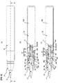
- FIGS. 1 to 3 are overall explanatory diagrams of an applicator according to an embodiment
- FIGS. 4 to 5 are part diagrams
- FIGS. 6 to 7 show modifications of the parts.
- the applicator is provided with a valve mechanism 14 that communicates an application liquid tank 10 and an applying part 12.
- the valve mechanism 14 includes a valve stem 16 and a valve holder 18 for holding the valve stem 16, and the valve mechanism 14 is constructed so as to allow the application liquid to flow through the gap between the valve stem 16 and the holder 18 when the pressure inside the application liquid tank 10 becomes higher than the outside pressure.
- the valve stem 16 is formed with an air exchange hole 20, which can be opened and closed by an opening/closing member 22 that opens/closes when the application liquid tank 10 side becomes negative or positive in pressure compared to the the applying part 12 side.
- the air exchange hole 20 of the valve stem 16 is formed along the axial direction.
- the opening/closing member 22 is arranged in an opening 20a on the application liquid tank 10 side of the air exchange hole 20.
- the opening/closing member 22 opens the opening 20a to allow air to flow for air exchange when the internal pressure of the application liquid tank 10 becomes negative, and closes the opening to prevent the application liquid from flowing into the air exchange hole 20 when the internal pressure becomes positive, thus producing a check valve.
- the applying part 12 has a tapered brush shape and is formed of a bundle of fibers.
- the applying part may be one that has a tapered form of an artificial material such as a fibrous or a porous resin material, or a bundle of natural product fibers. Examples of the material include PET (polyethylene terephthalate) and PBT (polybutylene terephthalate).
- the rear end portion of the applying part 12 is bundled and fixed by thermal fusing or the like to be formed with a flange 12a having an enlarged diameter.
- the application liquid tank 10 is a barrel cylinder integrated with the outer peripheral wall from the central portion to the rear portion of the applicator, and the application liquid tank 10 has a functional part that discharges the application liquid by radial deformation of the barrel cylinder.
- the application liquid tank 10 has a main body 10b that forms a flexible container and a front end part 10a that is made smaller in diameter than the main body.
- the rear portion of a front barrel 24 is fitted on the front end part 10a.
- the application liquid tank is a blow-molded flexible resin container having such a thickness as to elastically deform and increase the internal pressure when pressed in the radial direction by fingers.
- the application liquid tank 10 is a container of a barrel cylinder that the user holds in their hand to perform an applying operation. When the application liquid needs to be supplied, the application liquid tank is pressed in the radial direction with fingers to deform and reduce the interior volume to thereby increase the internal pressure.
- the application liquid tank 10 may be made of resin material such as PP (polypropylene), PE (polyethylene), PS (polystyrene), PET (polyethylene terephthalate), PC (polycarbonate), PA (polyamide), POM (polyacetal), PES (polyether sulfone), PEN (polyethylene naphthalate), vinyl chloride, EVOH (ethylene vinyl alcohol copolymer resin), PBT (polybutylene terephthalate), ABS (acrylonitrile butadiene styrene copolymer synthetic resin), or metal material such as stainless steel, iron, brass, copper and aluminum, as appropriate, and may be formed by a resin molding method such as blow molding, vacuum molding and injection molding, by one or combination of multiple metal processing methods such as cutting work, drawing, and press molding, or by forming a sealed bag with a thin film material such as a resin film, a metal foil by bonding, fusing, sewing, or any other method.
- resin material such as
- the front barrel 24 is formed in a substantially tubular hollow (mounting hole 24a) having a tapered front portion, and the applying part 12 is inserted with its front exposed.
- front and rear steps 24b and 24c are formed so that the inner diameter of the hollow becomes greater stepwise as it goes from the front to the rear.
- the flange 12a which is large in diameter at the rear end of the applying part 12 is caught by the front step 24b inside the front barrel 24 to prevent the applying part from falling off.
- an absorbent body socket 28 for holding an absorbent body 26 of the application liquid is mounted on the rear side of the flange 12a.
- the application liquid feeder 30 penetrates the axial core of the absorbent body 26 in the front-rear direction, and the front portion of the application liquid feeder 30 is inserted into the rear portion of the applying part 12 while the rear portion of the application liquid feeder 30 is fitted to and supported by an inner cylindrical portion 28a of the absorbent body socket 28.
- a flange 28b having an enlarged diameter is formed on the outer peripheral side of the absorbent body socket 28.
- the front face of the flange 28b abuts the rear step 24c of the front barrel 24 while the rear face of the flange 28b abuts the flange-shaped front end 18a of the valve holder 18 in the valve mechanism 14, so that the absorbent body socket is held and fixed between the front barrel 24 and the valve holder 18 inside the front barrel.
- the absorbent body socket 28 has a substantially cylindrical shape, and its outer peripheral portion has the flange 28b in the middle, which is larger in diameter than the front portion, whereas the outer peripheral portion behind the flange 28b is smaller in diameter than the front portion.
- a pair of beams 28c extending radially outward from the inner cylindrical portion 28a are integrally formed on the inner periphery of the absorbent body socket 28, so that the inner cylindrical portion 28a is fixed and supported.
- the front end faces of the inner cylindrical portion 28a and the beams 28c are flush with each other. This front endface serves as a receiving surface for the rear endface of the absorbent body 26 (see FIG. 1 ).
- the absorbent body 26 (see FIG. 1 ) is held in the absorbent body socket 28 with its outer peripheral side in contact with the inner peripheral surface of the absorbent body socket 28 and its rear endface abutted and supported by the front endface of the inner cylindrical portion 28a and the beams 28c.
- the hollows between the beams 28c and 28c constitute flow holes for the application liquid and an air exchange passage.
- An annular recess is formed on the outer peripheral surface in front of the flange 28b of the absorbent body socket 28, whereby the absorbent body socket is fitted in and fixed to the front barrel 24.
- an annular rib is formed on the outer peripheral surface behind the flange 28b, whereby the absorbent body socket is fitted and fixed to the valve holder 18.
- Examples of the so-called sponge material for the absorbent body 26 include fiber bundles of natural fiber, synthetic resin fiber, fiber bundle bodies processed from fiber bundles of felt or the like, hard sponge, and resin particle porous bodies and the like formed of resin particle sintered bodies.
- the application liquid feeder 30 is configured so that the capillary force of the application liquid feeder 30 is higher than that of the absorbent body 26, and may use a fiber bundle formed of one or a combination of natural fiber, animal hair fiber, polyacetal resin, acrylic resin, polyester resin, polyamide resin, polyurethane resin, polyolefin resin, polyvinyl resin, polycarbonate resin, polyether resin, polyphenylene, a processed product of a fiber bundle such as felt, hard sponge, resin particle porous body of resin particle sintered material, and a continuous porous passage formed of sliver core etc.
- the valve mechanism 14 includes the valve stem 16, the valve holder 18 for holding the valve stem 16 and a spring 32 for urging the valve stem rearward against the valve holder.
- valve holder 18 is fixed so that the front end 18a is in contact with the rear face of the flange 28b of the absorbent body socket 28 while the front end 18a and the flange 28b are sandwiched between the rear step 24c in the front barrel 24 and the front end part 10a of the application liquid tank 10.
- the valve holder 18 is a substantially cylindrical body that has a smaller diameter in the rear portion than in the front portion via a step 18b and a closed rear end, and an application liquid flow hole 18c is formed in the side wall of the rear portion.
- the valve stem 16 is a substantially tubular rod-like body that has an air exchange hole 20 formed inside, and an annular projected portion 16a having a backward inclined surface (tapered surface that narrows rearward) is formed on the outer peripheral surface.
- a coil spring 32 Inserted between the front face of the annular projected portion 16a and the absorbent body socket 28 (the rear face of the beams 28c) is a coil spring 32 made of resin or metal, which urges the stem 16 rearward. This urging force keeps contact between the backward slope of the annular projected portion 16a and the front interior face of the step 18b.
- the valve stem 16 has a small diameter in the front end and the annular projected portion 16a formed so as to protrude on the outer peripheral side in the middle part thereof.
- the opening/closing member 22 for opening/closing the opening 20a of the air exchange hole 20 is attached to the rear end of the valve stem.
- a mounting structure 16b in the rear end of the valve stem 16 of the embodiment is composed of a circumferential groove surrounding the outer peripheral side and a longitudinal groove extending from the circumferential groove to the rear endface.
- the opening/closing member 22 has a disk-shaped valve portion 22a, a ring-shaped portion 22b spaced from the valve portion 22a, and a joint 22c that connects the valve portion 22a and the ring-shaped portion 22b in the front-rear direction, which are integrally formed of a rubber-like elastic material.
- the rubber-like elastic material of the opening/closing member 22 may use, for example, NBR, silicone rubber, EPDM, fluorosilicone rubber, fluororubber, urethane rubber, natural rubber, chloroprene rubber, butadiene rubber, butyl rubber, styrene-based elastomer, vinyl chloride-based elastomer, olefin-based elastomer, polyester-based elastomer, polyamide-based elastomer, urethane-based elastomer and the like.
- valve portion 22a closes the rear end opening of the air exchange hole 20 of the valve stem 16
- the ring-shaped portion 22b fits in the circumferential groove of the mounting structure 16b
- the joint 22c fits in the longitudinal groove to create an airtight condition.
- valve stem 16 and the opening/closing member 22 may be integrally molded by two-color molding or the like, and in that case, the valve stem 16 and the opening/closing member 22 are preferably formed of non-adhesive materials.
- air exchange hole 20 may be arranged in the radial direction instead of the axial direction, and multiple exchange holes 20 may be formed.
- a stirring ball or the like that can stir the ink may be added.
- the application liquid flows through the flow hole 18c, passing through the gap between the annular projected portion 16a and the step 18b, and reaches the vicinity of the inner cylindrical portion 28a (the flow of the application liquid is indicated by a broken line E).
- the application liquid is supplied to the applying part 12 via the application liquid feeder 30 in the inner cylindrical portion 28a. Further, the application liquid passes between the beams 28c and 28c of the absorbent body socket 28, flows to the rear face of the absorbent body 26, and is temporarily stored in the absorbent body 26.
- the application liquid temporarily stored in the absorbent body 26 is supplied to the applying part 12 through the application liquid feeder 30 even when the valve stem 16 is closed.
- valve stem 16 of the valve mechanism 14 moves rearward from the urging force of the spring 32, and the annular projected portion 16a of the valve stem 16 abuts the step 18b of the valve holder 18 to close the valve.
- the valve mechanism 14 enables the application liquid to flow through the gap between the valve stem 16 and the valve holder 18 while provision of the air exchange hole 20 in the valve stem 16 enables the opening/closing member 22 to open/close when the pressure becomes negative or positive compared to the applying part 12 side. Therefore, as shown in FIG. 3 , the opening/closing member 22 opens to exchange air when the application liquid tank 10 becomes negative in pressure after release of the application liquid, so that the negative pressure in the application liquid tank 10 after release of the application liquid can be cancelled, thus making it possible to reliably eliminate continuation of the negative state.
- the application liquid tank 10 does not remain in a negative pressure state during an outflow operation of the application liquid, so that the application liquid tank 10 returns to its original shape and the application liquid tank 10 can be deformed again and favorably pressurized.
- problems such as defective liquid outflow can be resolved.
- an opening/closing member 22A can be formed as a band-shaped rubber elastic material that covers the surrounding area of openings 20a located on the application liquid tank 10 side of the air exchange hole 20.
- the same parts as those in FIGS. 1 to 3 and 5 are allotted with the same reference numerals.
- valve stem 16A is closed at the rear end thereof while openings 20a communicating with the air exchange hole 20 are formed on the side wall in the rear portion of the valve stem.
- the band-like opening/closing member 22A wide in the front-rear direction is formed so as to cover the openings 20a.
- a valve stem 16B and an opening/closing member 22B are provided to form a check valve structure.
- This check valve structure is used to replace the valve stem 16 and the opening/closing member 22 in the applicator shown in FIGS. 1 to 3 , whereas the other configurations of the applicator are overall the same.
- the valve stem 16B has an air exchange hole 20 penetrating therethrough from the front end to the rear end, and no opening is formed on the side wall.
- the opening/closing member 22B is attached to a front end 16Ba of the valve stem 16B.
- the opening/closing member 22B is formed of a rubber elastic material and comprises a bowl-shaped main part 22Ba and a funnel-shaped valve portion 22Bb, which is a smaller-diametric tubular part, extended, and tapered to the rear, from the main part.
- This pressure difference causes the opening/closing member 22B shown in FIG. 7 to open the valve portion 22Bb so that air is exchanged with the application liquid tank 10 (see FIG. 3 ) side through the air exchange hole 20.
- the application liquid tank 10 can exchange air via the opening/closing member 22B.
- an applicator which has a structure such that the application liquid tank is externally covered with a barrel cylinder while an actuator such as a knock mechanism is provided to change the internal pressure of the application liquid tank.
- the applicator of the present invention can be used as various applicators such as writing instruments, makeup tools, and paints.
- the present invention is suitable for an applicator having a thin pen core or a soft pen core, which is difficult to pump with the pen tip.
Landscapes
- Engineering & Computer Science (AREA)
- Mechanical Engineering (AREA)
- Pens And Brushes (AREA)
- Coating Apparatus (AREA)
- Containers And Packaging Bodies Having A Special Means To Remove Contents (AREA)
Abstract
Description
- The present invention relates to an applicator that supplies an application liquid in an ink tank to an applying part.
- When the amount of application liquid in the ink tank decreases, the pressure inside the ink tank becomes negative and it becomes difficult for the liquid to flow out, so air exchange is necessary.
- Patent Document 1 discloses a direct-liquid writing instrument in which a long communication pipe (flow hole) is arranged to extend into the ink tank from the partition wall behind the ink absorbent body while another short communication pipe (flow hole) is arranged to supply ink therethrough, so as to prevent the ink from being blown out by allowing the long communication pipe to exchange air.
- However, this writing instrument needs installation of the long communication pipe inside the ink tank, so that the ink tank and barrel cylinder becomes large.
- Further, Patent Documents 2 to 5 disclose applicators having pen tip pressing type valve mechanisms. These are configured to open the valve mechanism so as to allow the application liquid to flow when the pen tip is pressed from the front.
- However, when the writing part is a brush type, the rigidity of the brush is low so that the valve mechanism becomes difficult to operate when the brush is pressed from the front. That is, these applicators are not suitable for being applied to brush type applicators.
- In order to deal with the problem of the applicators with a flexible applying part while avoiding bulkiness of the ink tank, applicators using a valve mechanism that opens its valve by applying an increased pressure on the ink tank have been devised, instead of applicators using a long communication tube as in Patent Document 1 and instead of applicators using a valve mechanism that opens its valve as the applying part is pressed as disclosed in Patent Documents 2 to 5.
- There is an example of an applicator which includes an ink tank made of a blow molded container that can be deformed by pressing in the radial direction and a valve mechanism that opens its valve to discharge ink by increasing the inner pressure of the tank higher than the outside pressure by pressing or deforming the ink tank. Since this applicator can discharge ink as the inner pressure is increased by deforming the ink tank, this structure can be applied to a flexible applying part without upsizing the ink tank.
-
- [Patent Document 1]
Japanese Patent Application Laid-open No.2008-183896 - [Patent Document 2]
Japanese Patent Application Laid-open No.2005-343097 - [Patent Document 3]
Japanese Patent Application Laid-open No.2001-63276 - [Patent Document 4]
Japanese Patent Application Laid-open No.2001-80278 - [Patent Document 5]
Japanese Patent Application Laid-open No.2004-136538 - However, in the applicator using a valve mechanism that opens its valve by increasing the internal pressure of the ink tank, when, after the internal pressure is raised and the application liquid is discharged, the internal pressure is lowered by releasing the pressing force on the ink tank, the internal pressure becomes negative. In this this case, the valve mechanism does not operate and air exchange cannot be done, which is a problem. For example, an applicator that increases the internal pressure by deforming its ink tank cannot perform air exchange after ejection of ink, giving rise to a problem that the ink tank remains deformed without being able to be restored to its original shape.
- In view of the above problems, it is therefore an object of the present invention to provide an applicator capable of exchanging air after discharging the application liquid even if the applicator is equipped with a valve mechanism that opens its valve by increasing the internal pressure of the ink tank.
- The aspect of the present invention resides in an applicator comprising a valve mechanism that communicates an application liquid tank and an applying part, wherein: the valve mechanism has at least a valve stem and a valve holder for holding the valve stem therein; an application liquid can flow through a gap between the valve stem and the valve holder; the valve stem is formed with an air exchange hole; and, the air exchange hole can be opened and closed by an opening/closing member that opens/closes when the pressure on the application liquid tank side becomes negative or positive compared to that on the applying part side.
- According to the applicator of the present invention, the valve mechanism allows the application liquid to flow through the gap between the valve stem and the valve holder, and the valve stem is formed with an air exchange hole, which can be opened and closed by an opening/closing member that opens/closes when the pressure on the application liquid tank side becomes negative or positive compared to that on the applying part side. Since the opening/closing member is opened to exchange air when the pressure in the application liquid tank becomes negative after discharge of the application liquid, it is possible to surely eliminate the state where the inside of the application liquid tank remains in a negative pressure after discharge of the application liquid. Therefore, the present invention can provide excellent effect of solving the defective outflow problem that the application liquid tank remains in a negative pressure state at the time of using the applicator.
-
-
FIG. 1 is an overall explanatory diagram of an applicator according to an embodiment of the present invention, (a) an external view, (b) a vertical cross-section taken along a line B-B in (a), and (c) a vertical cross-section of a state where (b) is rotated 90° in the circumferential direction; -
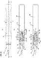
FIG. 2 is an explanatory diagram of the applicator ofFIG. 1 in a state where a valve stem is advanced by pressing a barrel cylinder, (a) an external view, (b) a vertical cross-section taken along a line B-B in (a), and (c) a vertical cross-section of a state where (b) is rotated 90° in the circumferential direction; -
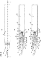
FIG. 3 is an explanatory diagram of the applicator ofFIG. 1 in a state where an opening/closing member of an air exchange hole is opened when the valve stem is retracted by releasing the pressing of the barrel cylinder, (a) an external view, (b) a vertical cross-section taken along a line B-B in (a), and (c) a vertical cross-section of a state where (b) is rotated 90° in the circumferential direction; -
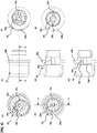
FIG. 4 is a part diagram of an absorbent body socket for holding an absorbent body (sponge) of an application liquid in the applicator ofFIG. 1 , (a) is a perspective view from the front, (b) a front view, (c) an external view, (d) a vertical cross-section taken along a D-D line in (b), (e) a vertical cross-section taken along a line E-E in (c), (f) a perspective view from the rear, and (g) a rear view; -
FIG. 5 is an partial assembly diagram of the valve stem and the opening/closing member in the applicator ofFIG. 1 , (a) a perspective view from the front, (b) a perspective view from the rear, (c) an external view, (d) a vertical cross-section taken along a line D-D in (e), (e) an external view in a state where (c) is rotated 90° in the circumferential direction, and (f) a vertical cross-section taken along a line F-F in (c), (g) a perspective view of the opening/closing member in a valve open state, viewed from the front, and (h) a perspective view of the opening/closing member in the valve open state, viewed from the rear; -
FIG. 6 is a partial assembly diagram of a valve stem and an opening/closing member according to a modification 1 of the applicator of the embodiment, (a) a perspective view from the front, (b) a perspective view from the rear, (c) an external view, (d) a vertical cross-section taken along a line D-D in (c), (e) a vertical cross-section in a state where (c) is rotated 90° in the circumferential direction; and, -
FIG. 7 is a partial assembly diagram of a valve stem and an opening/closing member according to a modification 2 of the applicator of the embodiment, (a) an external view of the valve stem with the opening/closing member attached, and (b) a detailed cross-section of the opening/closing member. - Hereinafter, embodiments of the present invention will be described with reference to the accompanying drawings.
-
FIGS. 1 to 3 are overall explanatory diagrams of an applicator according to an embodiment,FIGS. 4 to 5 are part diagrams, andFIGS. 6 to 7 show modifications of the parts. - As shown in
FIG. 1 , the applicator is provided with avalve mechanism 14 that communicates anapplication liquid tank 10 and an applyingpart 12. - The
valve mechanism 14 includes avalve stem 16 and avalve holder 18 for holding thevalve stem 16, and thevalve mechanism 14 is constructed so as to allow the application liquid to flow through the gap between thevalve stem 16 and theholder 18 when the pressure inside theapplication liquid tank 10 becomes higher than the outside pressure. - The
valve stem 16 is formed with anair exchange hole 20, which can be opened and closed by an opening/closing member 22 that opens/closes when theapplication liquid tank 10 side becomes negative or positive in pressure compared to the the applyingpart 12 side. - The
air exchange hole 20 of thevalve stem 16 is formed along the axial direction. - The opening/
closing member 22 is arranged in an opening 20a on theapplication liquid tank 10 side of theair exchange hole 20. The opening/closing member 22 opens the opening 20a to allow air to flow for air exchange when the internal pressure of theapplication liquid tank 10 becomes negative, and closes the opening to prevent the application liquid from flowing into theair exchange hole 20 when the internal pressure becomes positive, thus producing a check valve. - Next, each part will be explained in detail.
- The applying
part 12 has a tapered brush shape and is formed of a bundle of fibers. The applying part may be one that has a tapered form of an artificial material such as a fibrous or a porous resin material, or a bundle of natural product fibers. Examples of the material include PET (polyethylene terephthalate) and PBT (polybutylene terephthalate). - The rear end portion of the applying
part 12 is bundled and fixed by thermal fusing or the like to be formed with aflange 12a having an enlarged diameter. - The
application liquid tank 10 is a barrel cylinder integrated with the outer peripheral wall from the central portion to the rear portion of the applicator, and theapplication liquid tank 10 has a functional part that discharges the application liquid by radial deformation of the barrel cylinder. - The application
liquid tank 10 has amain body 10b that forms a flexible container and afront end part 10a that is made smaller in diameter than the main body. The rear portion of afront barrel 24 is fitted on thefront end part 10a. - Specifically, the application liquid tank is a blow-molded flexible resin container having such a thickness as to elastically deform and increase the internal pressure when pressed in the radial direction by fingers. The
application liquid tank 10 is a container of a barrel cylinder that the user holds in their hand to perform an applying operation. When the application liquid needs to be supplied, the application liquid tank is pressed in the radial direction with fingers to deform and reduce the interior volume to thereby increase the internal pressure. - The
application liquid tank 10 may be made of resin material such as PP (polypropylene), PE (polyethylene), PS (polystyrene), PET (polyethylene terephthalate), PC (polycarbonate), PA (polyamide), POM (polyacetal), PES (polyether sulfone), PEN (polyethylene naphthalate), vinyl chloride, EVOH (ethylene vinyl alcohol copolymer resin), PBT (polybutylene terephthalate), ABS (acrylonitrile butadiene styrene copolymer synthetic resin), or metal material such as stainless steel, iron, brass, copper and aluminum, as appropriate, and may be formed by a resin molding method such as blow molding, vacuum molding and injection molding, by one or combination of multiple metal processing methods such as cutting work, drawing, and press molding, or by forming a sealed bag with a thin film material such as a resin film, a metal foil by bonding, fusing, sewing, or any other method. - The
front barrel 24 is formed in a substantially tubular hollow (mountinghole 24a) having a tapered front portion, and the applyingpart 12 is inserted with its front exposed. - In the mounting
hole 24a inside thefront barrel 24, front andrear steps - The
flange 12a which is large in diameter at the rear end of the applyingpart 12 is caught by thefront step 24b inside thefront barrel 24 to prevent the applying part from falling off. Inside the mountinghole 24a, anabsorbent body socket 28 for holding anabsorbent body 26 of the application liquid is mounted on the rear side of theflange 12a. Theapplication liquid feeder 30 penetrates the axial core of theabsorbent body 26 in the front-rear direction, and the front portion of theapplication liquid feeder 30 is inserted into the rear portion of the applyingpart 12 while the rear portion of theapplication liquid feeder 30 is fitted to and supported by an innercylindrical portion 28a of theabsorbent body socket 28. - A
flange 28b having an enlarged diameter is formed on the outer peripheral side of theabsorbent body socket 28. The front face of theflange 28b abuts therear step 24c of thefront barrel 24 while the rear face of theflange 28b abuts the flange-shapedfront end 18a of thevalve holder 18 in thevalve mechanism 14, so that the absorbent body socket is held and fixed between thefront barrel 24 and thevalve holder 18 inside the front barrel. - As shown in
FIG. 4 , theabsorbent body socket 28 has a substantially cylindrical shape, and its outer peripheral portion has theflange 28b in the middle, which is larger in diameter than the front portion, whereas the outer peripheral portion behind theflange 28b is smaller in diameter than the front portion. A pair ofbeams 28c extending radially outward from the innercylindrical portion 28a are integrally formed on the inner periphery of theabsorbent body socket 28, so that the innercylindrical portion 28a is fixed and supported. The front end faces of the innercylindrical portion 28a and thebeams 28c are flush with each other. This front endface serves as a receiving surface for the rear endface of the absorbent body 26 (seeFIG. 1 ). - Therefore, the absorbent body 26 (see
FIG. 1 ) is held in theabsorbent body socket 28 with its outer peripheral side in contact with the inner peripheral surface of theabsorbent body socket 28 and its rear endface abutted and supported by the front endface of the innercylindrical portion 28a and thebeams 28c. - Regarding air exchange, with the application liquid feeder 30 (see
FIG. 1 ) fitted in the innercylindrical portion 28a, the hollows between thebeams flange 28b of theabsorbent body socket 28, whereby the absorbent body socket is fitted in and fixed to thefront barrel 24. Further, an annular rib is formed on the outer peripheral surface behind theflange 28b, whereby the absorbent body socket is fitted and fixed to thevalve holder 18. - Examples of the so-called sponge material for the
absorbent body 26 include fiber bundles of natural fiber, synthetic resin fiber, fiber bundle bodies processed from fiber bundles of felt or the like, hard sponge, and resin particle porous bodies and the like formed of resin particle sintered bodies. Theapplication liquid feeder 30 is configured so that the capillary force of theapplication liquid feeder 30 is higher than that of theabsorbent body 26, and may use a fiber bundle formed of one or a combination of natural fiber, animal hair fiber, polyacetal resin, acrylic resin, polyester resin, polyamide resin, polyurethane resin, polyolefin resin, polyvinyl resin, polycarbonate resin, polyether resin, polyphenylene, a processed product of a fiber bundle such as felt, hard sponge, resin particle porous body of resin particle sintered material, and a continuous porous passage formed of sliver core etc. - As shown in
FIG. 1 , thevalve mechanism 14 includes thevalve stem 16, thevalve holder 18 for holding thevalve stem 16 and aspring 32 for urging the valve stem rearward against the valve holder. - The
valve holder 18 is fixed so that thefront end 18a is in contact with the rear face of theflange 28b of theabsorbent body socket 28 while thefront end 18a and theflange 28b are sandwiched between therear step 24c in thefront barrel 24 and thefront end part 10a of theapplication liquid tank 10. - The
valve holder 18 is a substantially cylindrical body that has a smaller diameter in the rear portion than in the front portion via astep 18b and a closed rear end, and an applicationliquid flow hole 18c is formed in the side wall of the rear portion. - The valve stem 16 is a substantially tubular rod-like body that has an
air exchange hole 20 formed inside, and an annular projectedportion 16a having a backward inclined surface (tapered surface that narrows rearward) is formed on the outer peripheral surface. - Inserted between the front face of the annular projected
portion 16a and the absorbent body socket 28 (the rear face of thebeams 28c) is acoil spring 32 made of resin or metal, which urges thestem 16 rearward. This urging force keeps contact between the backward slope of the annular projectedportion 16a and the front interior face of thestep 18b. - As shown in
FIG. 5 , thevalve stem 16 has a small diameter in the front end and the annular projectedportion 16a formed so as to protrude on the outer peripheral side in the middle part thereof. The opening/closingmember 22 for opening/closing theopening 20a of theair exchange hole 20 is attached to the rear end of the valve stem. A mountingstructure 16b in the rear end of thevalve stem 16 of the embodiment is composed of a circumferential groove surrounding the outer peripheral side and a longitudinal groove extending from the circumferential groove to the rear endface. - As shown in
FIG. 5 , the opening/closingmember 22 has a disk-shapedvalve portion 22a, a ring-shapedportion 22b spaced from thevalve portion 22a, and a joint 22c that connects thevalve portion 22a and the ring-shapedportion 22b in the front-rear direction, which are integrally formed of a rubber-like elastic material. The rubber-like elastic material of the opening/closingmember 22 may use, for example, NBR, silicone rubber, EPDM, fluorosilicone rubber, fluororubber, urethane rubber, natural rubber, chloroprene rubber, butadiene rubber, butyl rubber, styrene-based elastomer, vinyl chloride-based elastomer, olefin-based elastomer, polyester-based elastomer, polyamide-based elastomer, urethane-based elastomer and the like. - In the state where the opening/closing
member 22 is set on thevalve stem 16, thevalve portion 22a closes the rear end opening of theair exchange hole 20 of thevalve stem 16, the ring-shapedportion 22b fits in the circumferential groove of the mountingstructure 16b, and the joint 22c fits in the longitudinal groove to create an airtight condition. - When the internal pressure of the application liquid tank 10 (see
FIG. 1 ) becomes lower than the outside air pressure, the pressure in theair exchange hole 20 increases, so that the joint 22c is stretched thanks to elastic deformation, as shown inFIGS. 5 (g) and 5 (h) , and thevalve portion 22a floats from the rear endface of thevalve stem 16 to create a gap δ and open the opening/closingmember 22. Therefore, air is exchanged through theair exchange hole 20. - The
valve stem 16 and the opening/closingmember 22 may be integrally molded by two-color molding or the like, and in that case, thevalve stem 16 and the opening/closingmember 22 are preferably formed of non-adhesive materials. - Further, the
air exchange hole 20 may be arranged in the radial direction instead of the axial direction, and multiple exchange holes 20 may be formed. - Further, depending on the ink stored in the tank, a stirring ball or the like that can stir the ink may be added.
- The operation of the applicator according to the embodiment will be described.
- As shown in
FIG. 2 , when the user of the applicator applies a radial force (indicated by reference numeral F) to theapplication liquid tank 10 by fingers, theapplication liquid tank 10 elastically deforms and the internal volume is reduced, so that the internal pressure increases compared to the outside air pressure. This difference in pressure generates a force for moving thevalve stem 16 of thevalve mechanism 14 forward. When the force exceeds the urging force of thespring 32, thevalve stem 16 moves forward and the annular projectedportion 16a of thevalve stem 16 separates from thestep 18b of thevalve holder 18 and opens the valve. - In the
valve mechanism 14, when the valve is opened, the application liquid flows through theflow hole 18c, passing through the gap between the annular projectedportion 16a and thestep 18b, and reaches the vicinity of the innercylindrical portion 28a (the flow of the application liquid is indicated by a broken line E). The application liquid is supplied to the applyingpart 12 via theapplication liquid feeder 30 in the innercylindrical portion 28a. Further, the application liquid passes between thebeams absorbent body socket 28, flows to the rear face of theabsorbent body 26, and is temporarily stored in theabsorbent body 26. The application liquid temporarily stored in theabsorbent body 26 is supplied to the applyingpart 12 through theapplication liquid feeder 30 even when thevalve stem 16 is closed. When the application liquid flows forward and the internal pressure of the tank is released, thevalve stem 16 of thevalve mechanism 14 moves rearward from the urging force of thespring 32, and the annular projectedportion 16a of thevalve stem 16 abuts thestep 18b of thevalve holder 18 to close the valve. - As shown in
FIG. 3 , when the pressing force acted by the fingers on theapplication liquid tank 10 is released, the elastic deformation of theapplication liquid tank 10 tries to return to the original state so that the internal volume increases. Resultantly, the internal pressure becomes lower than the outside air pressure, and becomes negative. The difference in pressure generates a pressure difference between theair exchange hole 20 inside thevalve stem 16 in theapplication liquid tank 10 and theapplication liquid tank 10. Due to this pressure difference, as shown inFIGS. 3 ,5(g) and 5(h) , thevalve portion 22a floats from the rear endface of thevalve stem 16 to create a gap δ, thus the opening/closingmember 22 opens. Therefore, theapplication liquid tank 10 exchanges air through theair exchange hole 20. - According to the embodiment, the
valve mechanism 14 enables the application liquid to flow through the gap between thevalve stem 16 and thevalve holder 18 while provision of theair exchange hole 20 in thevalve stem 16 enables the opening/closingmember 22 to open/close when the pressure becomes negative or positive compared to the applyingpart 12 side. Therefore, as shown inFIG. 3 , the opening/closingmember 22 opens to exchange air when theapplication liquid tank 10 becomes negative in pressure after release of the application liquid, so that the negative pressure in theapplication liquid tank 10 after release of the application liquid can be cancelled, thus making it possible to reliably eliminate continuation of the negative state. - As a result, when the applicator is used, the
application liquid tank 10 does not remain in a negative pressure state during an outflow operation of the application liquid, so that theapplication liquid tank 10 returns to its original shape and theapplication liquid tank 10 can be deformed again and favorably pressurized. Thus, problems such as defective liquid outflow can be resolved. - The opening/closing member is not limited to the embodiment. As a modification 1 shown in
FIG. 6 , an opening/closingmember 22A can be formed as a band-shaped rubber elastic material that covers the surrounding area ofopenings 20a located on theapplication liquid tank 10 side of theair exchange hole 20. The same parts as those inFIGS. 1 to 3 and5 are allotted with the same reference numerals. - In
FIG. 6 , the valve stem 16A is closed at the rear end thereof whileopenings 20a communicating with theair exchange hole 20 are formed on the side wall in the rear portion of the valve stem. The band-like opening/closingmember 22A wide in the front-rear direction is formed so as to cover theopenings 20a. - In a state where the
valve mechanism 14 is closed as shown inFIG. 3 , a pressure difference is generated between theair exchange hole 20 in thevalve stem 16 and theapplication liquid tank 10 due to a negative pressure in theapplication liquid tank 10. This pressure difference creates, as shown inFIG. 6 , a gap between the opening/closingmember 22A and the outer surface of the valve stem 16A, so that the opening/closingmember 22A opens. Therefore, theapplication liquid tank 10 can exchange air through theair exchange hole 20. - In a modification 2 shown in
FIG. 7 , avalve stem 16B and an opening/closingmember 22B are provided to form a check valve structure. This check valve structure is used to replace thevalve stem 16 and the opening/closingmember 22 in the applicator shown inFIGS. 1 to 3 , whereas the other configurations of the applicator are overall the same. - The valve stem 16B has an
air exchange hole 20 penetrating therethrough from the front end to the rear end, and no opening is formed on the side wall. The opening/closingmember 22B is attached to a front end 16Ba of thevalve stem 16B. The opening/closingmember 22B is formed of a rubber elastic material and comprises a bowl-shaped main part 22Ba and a funnel-shaped valve portion 22Bb, which is a smaller-diametric tubular part, extended, and tapered to the rear, from the main part. In a state where thevalve mechanism 14 is closed as shown inFIG. 3 , a pressure difference is generated between the front side of thevalve stem 16 and theapplication liquid tank 10 due to a negative pressure in theapplication liquid tank 10. This pressure difference causes the opening/closingmember 22B shown inFIG. 7 to open the valve portion 22Bb so that air is exchanged with the application liquid tank 10 (seeFIG. 3 ) side through theair exchange hole 20. Thus, theapplication liquid tank 10 can exchange air via the opening/closingmember 22B. - Other than the embodiment of the applicator, it is possible to provide an applicator which has a structure such that the application liquid tank is externally covered with a barrel cylinder while an actuator such as a knock mechanism is provided to change the internal pressure of the application liquid tank.
- The applicator of the present invention can be used as various applicators such as writing instruments, makeup tools, and paints. Particularly, the present invention is suitable for an applicator having a thin pen core or a soft pen core, which is difficult to pump with the pen tip.
-
- 10 application liquid tank
- 12 applying part
- 14 valve mechanism
- 16 valve stem
- 16A valve stem (modification 1)
- 16B valve stem (modification 2)
- 16Ba front end
- 16a annular projected portion
- 16b mounting structure
- 18 valve holder
- 20 air exchange hole
- 20a opening
- 22 opening/closing member
- 22A opening/closing member (modification 1)
- 22B opening/closing member (modification 2)
- 26 absorbent body
- 28 absorbent body socket
- 30 application liquid feeder
32 spring
Claims (6)
- An applicator comprising a valve mechanism that communicates an application liquid tank and an applying part, wherein:the valve mechanism has at least a valve stem and a valve holder for holding the valve stem therein;an application liquid can flow through a gap between the valve stem and the valve holder;the valve stem is formed with an air exchange hole; and,the air exchange hole can be opened and closed by an opening/closing member that opens/closes when the pressure on the application liquid tank side becomes negative or positive compared to that on the applying part side.
- The applicator according to claim 1, wherein the air exchange hole is formed in the valve stem along the axial direction thereof.
- The applicator according to claim 1 or 2, wherein the opening/closing member is a member made of a rubber elastic material that covers the opening of the air exchange hole on the application liquid tank side.
- The applicator according to claim 1 or 2, wherein the opening/closing member is a check valve arranged at the opening on the application liquid tank side of the air exchange hole.
- The applicator according to any one of claims 1 to 4, wherein the application liquid tank is a flexible container.
- The applicator according to any one of claims 1 to 5, wherein the application liquid tank forms a barrel cylinder and provides the function of an actuator for causing the application liquid to flow out by deformation of the barrel cylinder.
Applications Claiming Priority (1)
| Application Number | Priority Date | Filing Date | Title |
|---|---|---|---|
| JP2020008440A JP7441655B2 (en) | 2020-01-22 | 2020-01-22 | applicator |
Publications (1)
| Publication Number | Publication Date |
|---|---|
| EP3854603A1 true EP3854603A1 (en) | 2021-07-28 |
Family
ID=74191586
Family Applications (1)
| Application Number | Title | Priority Date | Filing Date |
|---|---|---|---|
| EP21152289.1A Pending EP3854603A1 (en) | 2020-01-22 | 2021-01-19 | Applicator |
Country Status (3)
| Country | Link |
|---|---|
| US (1) | US11318777B2 (en) |
| EP (1) | EP3854603A1 (en) |
| JP (1) | JP7441655B2 (en) |
Families Citing this family (1)
| Publication number | Priority date | Publication date | Assignee | Title |
|---|---|---|---|---|
| KR20250114295A (en) * | 2022-11-30 | 2025-07-29 | 미쓰비시 엔피쯔 가부시키가이샤 | Applicator |
Citations (8)
| Publication number | Priority date | Publication date | Assignee | Title |
|---|---|---|---|---|
| US2996750A (en) * | 1959-04-06 | 1961-08-22 | Cholet Bertram | Fountain pen |
| US5735624A (en) * | 1993-12-17 | 1998-04-07 | Parker Pen Products | Relating to writing instruments |
| US6106180A (en) * | 1998-10-20 | 2000-08-22 | Anderka; Gerold | Handwriting or ink applying device |
| JP2001063276A (en) | 1999-08-25 | 2001-03-13 | Pentel Corp | Writing implement |
| JP2001080278A (en) | 1999-09-14 | 2001-03-27 | Sakura Color Prod Corp | Applicator |
| JP2004136538A (en) | 2002-10-17 | 2004-05-13 | Mitsubishi Pencil Co Ltd | Writing implement |
| JP2005343097A (en) | 2004-06-07 | 2005-12-15 | Mitsubishi Pencil Co Ltd | Liquid applicator |
| JP2008183896A (en) | 2006-03-09 | 2008-08-14 | Pilot Ink Co Ltd | Direct liquid writing instrument |
Family Cites Families (11)
| Publication number | Priority date | Publication date | Assignee | Title |
|---|---|---|---|---|
| US4102476A (en) * | 1977-02-22 | 1978-07-25 | Ciba-Geigy Corporation | Squeeze bottle dispenser with air check valve on cover |
| JPH0453976Y2 (en) * | 1986-02-10 | 1992-12-18 | ||
| JPH0775753A (en) * | 1993-06-25 | 1995-03-20 | Pilot Ink Co Ltd | Coating container |
| JPH07265780A (en) * | 1994-03-31 | 1995-10-17 | Pentel Kk | Applicator |
| JP3229224B2 (en) * | 1996-10-30 | 2001-11-19 | セーラー万年筆株式会社 | Aqueous ballpoint pen |
| US5927565A (en) * | 1997-05-16 | 1999-07-27 | Paczonay; Joseph R. | Vented valve assembly for liquid containers |
| ATE225743T1 (en) * | 1998-08-03 | 2002-10-15 | Veresk Biosystems Ltd | CONTAINER VALVE |
| US6554521B1 (en) | 1999-09-14 | 2003-04-29 | Sakura Color Products Corporation | Applicator |
| JP4218151B2 (en) * | 1999-09-30 | 2009-02-04 | ぺんてる株式会社 | Applicator with valve |
| KR100946428B1 (en) | 2006-03-09 | 2010-03-10 | 파일롯트 잉크 가부시키가이샤 | Direct Writing Instruments |
| US20140183154A1 (en) * | 2011-07-25 | 2014-07-03 | Jan Essebaggers | Self closing flow control device with adjustable actuator element for container closures |
-
2020
- 2020-01-22 JP JP2020008440A patent/JP7441655B2/en active Active
-
2021
- 2021-01-19 EP EP21152289.1A patent/EP3854603A1/en active Pending
- 2021-01-20 US US17/152,841 patent/US11318777B2/en active Active
Patent Citations (8)
| Publication number | Priority date | Publication date | Assignee | Title |
|---|---|---|---|---|
| US2996750A (en) * | 1959-04-06 | 1961-08-22 | Cholet Bertram | Fountain pen |
| US5735624A (en) * | 1993-12-17 | 1998-04-07 | Parker Pen Products | Relating to writing instruments |
| US6106180A (en) * | 1998-10-20 | 2000-08-22 | Anderka; Gerold | Handwriting or ink applying device |
| JP2001063276A (en) | 1999-08-25 | 2001-03-13 | Pentel Corp | Writing implement |
| JP2001080278A (en) | 1999-09-14 | 2001-03-27 | Sakura Color Prod Corp | Applicator |
| JP2004136538A (en) | 2002-10-17 | 2004-05-13 | Mitsubishi Pencil Co Ltd | Writing implement |
| JP2005343097A (en) | 2004-06-07 | 2005-12-15 | Mitsubishi Pencil Co Ltd | Liquid applicator |
| JP2008183896A (en) | 2006-03-09 | 2008-08-14 | Pilot Ink Co Ltd | Direct liquid writing instrument |
Also Published As
| Publication number | Publication date |
|---|---|
| US20210221162A1 (en) | 2021-07-22 |
| JP2021115707A (en) | 2021-08-10 |
| JP7441655B2 (en) | 2024-03-01 |
| US11318777B2 (en) | 2022-05-03 |
Similar Documents
| Publication | Publication Date | Title |
|---|---|---|
| JP4848068B2 (en) | Direct liquid writing instrument | |
| US11318777B2 (en) | Applicator | |
| KR100763662B1 (en) | Writing instrument | |
| JP3719765B2 (en) | Tail-end knock structure for liquid applicators such as writing utensils and cosmetics | |
| JP3929571B2 (en) | Writing instrument | |
| JP5794732B2 (en) | Replenisher and writing instrument set with replenisher | |
| EP1674289B1 (en) | Writing implement | |
| JP6069003B2 (en) | Liquid applicator | |
| JP2005131943A (en) | Nib for pigment ink and writing instrument | |
| JP2012135916A (en) | Ink refill device and writing implement set with ink refill device | |
| EP1798043A1 (en) | Differential pressure valve unit | |
| JP4010075B2 (en) | Writing instrument | |
| JP2011235488A (en) | Writing device | |
| JP2003136883A (en) | Writing implement | |
| JP3152083U (en) | Direct liquid writing instrument | |
| JP4680751B2 (en) | Writing instrument | |
| JP2021045850A (en) | Painter | |
| JP2021003842A (en) | Applicator | |
| JP4750590B2 (en) | Direct liquid writing instrument | |
| CN121794134A (en) | Writing tool | |
| JP2008044285A (en) | Direct liquid writing instrument | |
| JP2025039429A (en) | Writing implements | |
| JP2008087280A (en) | Liquid writing instrument | |
| WO2025053261A1 (en) | Writing instrument | |
| JP2025039428A (en) | Writing implements |
Legal Events
| Date | Code | Title | Description |
|---|---|---|---|
| PUAI | Public reference made under article 153(3) epc to a published international application that has entered the european phase |
Free format text: ORIGINAL CODE: 0009012 |
|
| STAA | Information on the status of an ep patent application or granted ep patent |
Free format text: STATUS: THE APPLICATION HAS BEEN PUBLISHED |
|
| AK | Designated contracting states |
Kind code of ref document: A1 Designated state(s): AL AT BE BG CH CY CZ DE DK EE ES FI FR GB GR HR HU IE IS IT LI LT LU LV MC MK MT NL NO PL PT RO RS SE SI SK SM TR |
|
| STAA | Information on the status of an ep patent application or granted ep patent |
Free format text: STATUS: REQUEST FOR EXAMINATION WAS MADE |
|
| 17P | Request for examination filed |
Effective date: 20211221 |
|
| RBV | Designated contracting states (corrected) |
Designated state(s): AL AT BE BG CH CY CZ DE DK EE ES FI FR GB GR HR HU IE IS IT LI LT LU LV MC MK MT NL NO PL PT RO RS SE SI SK SM TR |
|
| RAP3 | Party data changed (applicant data changed or rights of an application transferred) |
Owner name: MITSUBISHI PENCIL COMPANY, LIMITED |
|
| STAA | Information on the status of an ep patent application or granted ep patent |
Free format text: STATUS: EXAMINATION IS IN PROGRESS |
|
| 17Q | First examination report despatched |
Effective date: 20241004 |