EP3854574A1 - Tire mold, production method for tire, and tire - Google Patents
Tire mold, production method for tire, and tire Download PDFInfo
- Publication number
- EP3854574A1 EP3854574A1 EP21151778.4A EP21151778A EP3854574A1 EP 3854574 A1 EP3854574 A1 EP 3854574A1 EP 21151778 A EP21151778 A EP 21151778A EP 3854574 A1 EP3854574 A1 EP 3854574A1
- Authority
- EP
- European Patent Office
- Prior art keywords
- tread
- land
- tire
- forming
- shoulder
- Prior art date
- Legal status (The legal status is an assumption and is not a legal conclusion. Google has not performed a legal analysis and makes no representation as to the accuracy of the status listed.)
- Granted
Links
Images


Classifications
-
- B—PERFORMING OPERATIONS; TRANSPORTING
- B29—WORKING OF PLASTICS; WORKING OF SUBSTANCES IN A PLASTIC STATE IN GENERAL
- B29D—PRODUCING PARTICULAR ARTICLES FROM PLASTICS OR FROM SUBSTANCES IN A PLASTIC STATE
- B29D30/00—Producing pneumatic or solid tyres or parts thereof
- B29D30/06—Pneumatic tyres or parts thereof (e.g. produced by casting, moulding, compression moulding, injection moulding, centrifugal casting)
- B29D30/0601—Vulcanising tyres; Vulcanising presses for tyres
- B29D30/0606—Vulcanising moulds not integral with vulcanising presses
-
- B—PERFORMING OPERATIONS; TRANSPORTING
- B60—VEHICLES IN GENERAL
- B60C—VEHICLE TYRES; TYRE INFLATION; TYRE CHANGING; CONNECTING VALVES TO INFLATABLE ELASTIC BODIES IN GENERAL; DEVICES OR ARRANGEMENTS RELATED TO TYRES
- B60C11/00—Tyre tread bands; Tread patterns; Anti-skid inserts
- B60C11/03—Tread patterns
- B60C11/12—Tread patterns characterised by the use of narrow slits or incisions, e.g. sipes
-
- B—PERFORMING OPERATIONS; TRANSPORTING
- B29—WORKING OF PLASTICS; WORKING OF SUBSTANCES IN A PLASTIC STATE IN GENERAL
- B29D—PRODUCING PARTICULAR ARTICLES FROM PLASTICS OR FROM SUBSTANCES IN A PLASTIC STATE
- B29D30/00—Producing pneumatic or solid tyres or parts thereof
- B29D30/06—Pneumatic tyres or parts thereof (e.g. produced by casting, moulding, compression moulding, injection moulding, centrifugal casting)
- B29D30/0601—Vulcanising tyres; Vulcanising presses for tyres
- B29D30/0606—Vulcanising moulds not integral with vulcanising presses
- B29D2030/0607—Constructional features of the moulds
- B29D2030/0612—Means for forming recesses or protrusions in the tyres, e.g. grooves or ribs, to create the tread or sidewalls patterns
-
- B—PERFORMING OPERATIONS; TRANSPORTING
- B29—WORKING OF PLASTICS; WORKING OF SUBSTANCES IN A PLASTIC STATE IN GENERAL
- B29D—PRODUCING PARTICULAR ARTICLES FROM PLASTICS OR FROM SUBSTANCES IN A PLASTIC STATE
- B29D30/00—Producing pneumatic or solid tyres or parts thereof
- B29D30/06—Pneumatic tyres or parts thereof (e.g. produced by casting, moulding, compression moulding, injection moulding, centrifugal casting)
- B29D30/0601—Vulcanising tyres; Vulcanising presses for tyres
- B29D30/0606—Vulcanising moulds not integral with vulcanising presses
- B29D2030/0607—Constructional features of the moulds
- B29D2030/0616—Surface structure of the mould, e.g. roughness, arrangement of slits, grooves or channels
-
- B—PERFORMING OPERATIONS; TRANSPORTING
- B60—VEHICLES IN GENERAL
- B60C—VEHICLE TYRES; TYRE INFLATION; TYRE CHANGING; CONNECTING VALVES TO INFLATABLE ELASTIC BODIES IN GENERAL; DEVICES OR ARRANGEMENTS RELATED TO TYRES
- B60C11/00—Tyre tread bands; Tread patterns; Anti-skid inserts
- B60C11/03—Tread patterns
- B60C2011/0337—Tread patterns characterised by particular design features of the pattern
- B60C2011/0339—Grooves
- B60C2011/0341—Circumferential grooves
Definitions
- the present invention relates a tire mold, a production method for a tire, and a tire.
- a tire is obtained by pressurizing and heating a tire in an uncrosslinked state (hereinafter, green tire) within a mold.
- a plurality of circumferential grooves are formed on the tread of the tire so as to be aligned in the axial direction, whereby land portions are formed therein.
- projections corresponding to the circumferential grooves are provided on a tread-forming surface of the mold. By pressing the green tire against the projections, the circumferential grooves are formed on the tread.
- the tire includes, for example, a belt including a large number of aligned cords, on the radially inner side of the tread.
- Various measures are taken in the production of tires such that the belt does not become wavy as a result of pressing the green tire against the projections (for example, Japanese Laid-Open Patent Publication No. 2014-61602 ).
- unvulcanized rubber a part of a rubber composition in an unvulcanized state (hereinafter, unvulcanized rubber) pressed by the projections flows into portions where the land portions are to be formed.
- unvulcanized rubber does not flow easily, disturbance may occur in the inner surface shape of the tread.
- the volume of the unvulcanized rubber pressed against the projection is large, so that it is difficult to control the thickness of the tread, and the belt may become wavy.
- FIG. 9 shows the contour of each land portion included in the ground-contact surface.
- FIG. 10 shows a ground-contact pressure distribution of the tire.
- the right side shows a ground-contact pressure distribution of a shoulder land portion
- the left side shows a ground-contact pressure distribution of a middle land portion.
- the outer edge in the circumferential direction of each land portion has a shape that is convex inward.
- the ground-contact pressure is locally increased at the edge of each land portion. Specifically, a ground-contact pressure difference of about 200 kPa is confirmed in the middle land portion, and a ground-contact pressure difference of about 250 kPa is confirmed in the shoulder land portion.
- the disturbance in the inner surface shape of the tread influences the ground-contact surface shape and the ground-contact pressure distribution of the tire.
- the tire can be more sufficiently brought into contact with a road surface, so that it is expected that steering stability can be further improved.
- a local increase in ground-contact pressure is also suppressed, so that it is also expected that wear resistance can be improved.
- the present invention has been made in view of the above circumstances, and an object of the present invention is to provide a tire mold and a production method for a tire that are capable of making a ground-contact surface shape and a ground-contact pressure distribution appropriate, and a tire having a ground-contact surface shape and a ground-contact pressure distribution that are made appropriate.
- a tire mold according to an aspect of the present invention is a mold used for producing a tire including a tread having a tread surface that comes into contact with a road surface, at least two circumferential grooves having a groove width of not less than 9 mm being formed on the tread so as to extend in a circumferential direction, thereby forming at least three land portions in the tread, the tread surface including the at least two circumferential grooves and at least three land surfaces that are outer surfaces of the at least three land portions, the mold including a tread-forming surface for shaping the tread surface.
- the tread-forming surface includes at least two projections for forming the at least two circumferential grooves, and at least three land surface-forming portions for forming the at least three land surfaces.
- a contour of a land surface-forming portion located between two projections among the at least three land surface-forming portions is represented by a single circular arc that is convex outward.
- one projection is a wide projection having a larger width than the other projection
- the other projection is a narrow projection having a smaller width than the one projection
- a wide-side drop distance MDW that is a distance from the reference surface of the tread-forming surface to an end on the wide projection side of the land surface-forming portion is longer than a narrow-side drop distance MDN that is a distance from the reference surface of the tread-forming surface to an end on the narrow projection side of the land surface-forming portion.
- the narrow-side drop distance MDN is not less than 0.01 mm
- the wide-side drop distance MDW is not greater than 0.3 mm
- the narrow-side drop distance MDN satisfies the following formula (MN1) represented using a width MRN of the narrow projection
- the wide-side drop distance MDW satisfies the following formula (MW1) represented using a width MRW of the wide projection.
- a tire mold according to an aspect of the present invention is a mold used for producing a tire including a tread having a tread surface that comes into contact with a road surface, at least two circumferential grooves having a groove width of not less than 9 mm being formed on the tread so as to extend in a circumferential direction, thereby forming at least three land portions in the tread, the tread surface including the at least two circumferential grooves and at least three land surfaces that are outer surfaces of the at least three land portions, the mold including a tread-forming surface for shaping the tread surface.
- the tread-forming surface includes at least two projections for forming the at least two circumferential grooves, and at least three land surface-forming portions for forming the at least three land surfaces.
- a land surface-forming portion located on each outer side in an axial direction is a shoulder land surface-forming portion
- a land surface-forming portion located inward of the shoulder land surface-forming portion is a middle land surface-forming portion
- a projection between the shoulder land surface-forming portion and the middle land surface-forming portion is a shoulder projection
- a contour of a portion from an end on the shoulder projection side of the shoulder land surface-forming portion to the reference position is represented by a single circular arc.
- a distance MZ from the end on the shoulder projection side to the reference position satisfies the following formula (MS1). MY / 2 ⁇ 5 ⁇ MZ ⁇ MY / 2 + 5
- a shoulder-side drop distance MDS that is a distance from the reference surface of the tread-forming surface to the end on the shoulder projection side of the shoulder land surface-forming portion is not less than 0.05 mm and not greater than 0.6 mm.
- the tread includes a cap portion including the tread surface, and an unvulcanized rubber for the cap portion has a Mooney viscosity of not less than 80.
- a production method for a tire according to an aspect of the present invention includes a step of pressurizing and heating a green tire using any of the tire molds described above.
- a tire according to an aspect of the present invention includes a tread having a tread surface that comes into contact with a road surface, at least two circumferential grooves having a groove width of not less than 9 mm are formed on the tread so as to extend in a circumferential direction, thereby forming at least three land portions in the tread, and the tread surface includes the at least two circumferential grooves and at least three land surfaces that are outer surfaces of the at least three land portions.
- a contour of a land surface located between two circumferential grooves among the at least three land surfaces is represented by a single circular arc that is convex outward.
- one circumferential groove is a wide circumferential groove having a larger groove width than the other circumferential groove
- the other circumferential groove is a narrow circumferential groove having a smaller groove width than the one circumferential groove
- a wide-side drop distance TDW that is a distance from the reference surface of the tread surface to an end on the wide circumferential groove side of the land surface is longer than a narrow-side drop distance TDN that is a distance from the reference surface of the tread surface to an end on the narrow circumferential groove side of the land surface.
- a tire according to another aspect of the present invention includes a tread having a tread surface that comes into contact with a road surface, at least two circumferential grooves having a groove width of not less than 9 mm are formed on the tread so as to extend in a circumferential direction, thereby forming at least three land portions in the tread, and the tread surface includes the at least two circumferential grooves and at least three land surfaces that are outer surfaces of the at least three land portions.
- a land surface located on each outer side in an axial direction is a shoulder land surface
- a land surface located inward of the shoulder land surface is a middle land surface
- a circumferential groove between the shoulder land surface and the middle land surface is a shoulder circumferential groove.
- a contour of a portion from an end on the shoulder circumferential groove side of the shoulder land surface to the reference position is represented by a single circular arc.
- the ground-contact surface shape and the ground-contact pressure distribution of a tire can be made appropriate.
- a tire obtained by the tire mold and the production method for a tire an appropriate ground-contact surface shape and an appropriate ground-contact pressure distribution are obtained, and thus steering stability and wear resistance can be improved.
- a state where a tire is mounted on a normal rim, the internal pressure of the tire is adjusted to a normal internal pressure, and no load is applied to the tire is referred to as a normal state.
- the dimensions and angles of each component of the tire are measured in the normal state.
- the normal rim means a rim specified in a standard on which the tire is based.
- the "standard rim” in the JATMA standard, the "Design Rim” in the TRA standard, and the “Measuring Rim” in the ETRTO standard are normal rims.
- the normal internal pressure means an internal pressure specified in the standard on which the tire is based.
- the "highest air pressure” in the JATMA standard, the “maximum value” recited in “TIRE LOAD LIMITS AT VARIOUS COLD INFLATION PRESSURES" in the TRA standard, and the “INFLATION PRESSURE” in the ETRTO standard are normal internal pressures.
- the normal internal pressure of a tire for a passenger car is, for example, 180 kPa.
- a normal load means a load specified in the standard on which the tire is based.
- the "maximum load capacity" in the JATMA standard, the “maximum value” recited in the "TIRE LOAD LIMITS AT VARIOUS COLD INFLATION PRESSURES" in the TRA standard, and the “LOAD CAPACITY” in the ETRTO standard are normal loads.
- the normal load of a tire for a passenger car is, for example, a load corresponding to 88% of the above load.
- FIG. 1 shows a part of a pneumatic tire 2 (hereinafter, sometimes referred to simply as "tire 2") according to an embodiment of the present invention.
- the tire 2 is mounted to a passenger car.
- FIG. 1 shows a part of a cross-section of the tire 2 along a plane including the rotation axis of the tire 2.
- the right-left direction is the axial direction of the tire 2
- the up-down direction is the radial direction of the tire 2.
- the direction perpendicular to the surface of the sheet of FIG. 1 is the circumferential direction of the tire 2.
- an alternate long and short dash line CL represents the equator plane of the tire 2.
- the tire 2 includes a tread 4, a pair of sidewalls 6, a pair of clinches 8, a pair of beads 10, a carcass 12, a cord reinforcing layer 14, a pair of chafers 16, an inner liner 18, and a pair of rubber reinforcing layers 20.
- the tread 4 has a tread surface 22 that comes into contact with a road surface.
- the tread 4 is located outward of the cord reinforcing layer 14 in the radial direction.
- the tread 4 includes a base portion 24 and a cap portion 26.
- the base portion 24 forms a radially inner portion of the tread 4.
- the base portion 24 is formed from a crosslinked rubber for which heat generation properties are taken into consideration.
- the cap portion 26 is located radially outward of the base portion 24. In the tire 2, the cap portion 26 comes into contact with a road surface.
- the outer surface of the cap portion 26 includes the above-described tread surface 22.
- the cap portion 26 is formed from a crosslinked rubber for which wear resistance and grip performance are taken into consideration.
- the tread 4 may be composed of only the cap portion 26.
- Each sidewall 6 extends from an end of the tread 4 inwardly in the radial direction along the carcass 12.
- the sidewall 6 is formed from a crosslinked rubber.
- Each clinch 8 is located radially inward of the sidewall 6. Although not shown, the clinch 8 comes into contact with a rim (not shown).
- the clinch 8 is formed from a crosslinked rubber for which wear resistance is taken into consideration.
- Each bead 10 is located axially inward of the clinch 8.
- the bead 10 includes a core 28 and an apex 30.
- the core 28 includes a wire made of steel.
- the apex 30 is located radially outward of the core 28.
- the apex 30 is formed from a crosslinked rubber that has high stiffness. As shown in FIG. 1 , the size of the apex 30 is smaller than that of a conventional apex.
- the core 28 may include two cores aligned in the axial direction.
- a later-described carcass ply is not turned up around the core 28, but an end portion of the carcass ply is interposed between these two cores.
- the carcass 12 is located inward of the tread 4, the pair of sidewalls 6, and the pair of clinches 8.
- the carcass 12 extends on and between one bead 10 and the other bead 10.
- the carcass 12 has a radial structure.
- the carcass 12 includes at least one carcass ply 32.
- the carcass 12 of the tire 2 is composed of one carcass ply 32.
- the carcass ply 32 is turned up around the core 28 of each bead 10.
- the carcass ply 32 includes a large number of cords aligned with each other, which are not shown.
- the cord reinforcing layer 14 includes a belt 34 and a band 36.
- the belt 34 forms an inner portion of the cord reinforcing layer 14, and the band 36 forms an outer portion of the cord reinforcing layer 14.
- the cord reinforcing layer 14 may be composed of only the belt 34, or may be composed of only the band 36.
- the belt 34 is laminated on the carcass 12 on the radially inner side of the tread 4.
- the belt 34 includes at least two belt plies 38 laminated in the radial direction.
- the belt 34 of the tire 2 is composed of two belt plies 38.
- Each of the two belt plies 38 includes a large number of cords aligned with each other, which are not shown. These cords are inclined relative to the equator plane CL.
- the material of each cord is steel.
- the band 36 is located inward of the tread 4 in the radial direction.
- the band 36 is located between the tread 4 and the belt 34 in the radial direction.
- the band 36 of the tire 2 includes a full band 36f and a pair of edge bands 36e located outward of the full band 36f.
- the band 36 may be composed of only the full band 36f, or may be composed of only the pair of edge bands 36e.
- the band 36 includes cords, which are not shown. In the full band 36f and the edge bands 36e, the cords are spirally wound in the circumferential direction. A cord formed from an organic fiber is used as each cord of the band 36.
- Each chafer 16 is located radially inward of the bead 10. Although not shown, the chafer 16 comes into contact with the rim.
- the chafer 16 includes a fabric and a rubber with which the fabric is impregnated.
- the chafer 16 may be composed of a member formed from a crosslinked rubber.
- the inner liner 18 is located inward of the carcass 12.
- the inner liner 18 forms an inner surface of the tire 2.
- the inner liner 18 is formed from a crosslinked rubber that has low gas permeability.
- Each rubber reinforcing layer 20 is located outward of the apex 30 in the axial direction.
- the rubber reinforcing layer 20 is located between the carcass 12 and the clinch 8.
- the rubber reinforcing layer 20 is formed from a crosslinked rubber.
- the material of the rubber reinforcing layer 20 is the same as that of the apex 30.
- the rubber reinforcing layer 20 does not have to be provided. In this case, an apex having a conventional size is adopted.
- grooves 40 are formed on the tread 4 of the tire 2 (specifically, the cap portion 26). Accordingly, a tread pattern is formed.
- Each groove 42 of the tire 2 shown in FIG. 1 is a part of the grooves 40 which form the tread pattern.
- the groove 42 extends in the circumferential direction.
- the groove 42 is a circumferential groove.
- the circumferential groove 42 has a groove width of not less than 9 mm and not greater than 20 mm, which is set as appropriate in accordance with the specifications of the tire 2.
- the circumferential groove 42 has a groove depth of not less than 5 mm and not greater than 15 mm.
- the groove width is represented as the distance from one edge of the groove 40 to the other edge of the groove 40.
- the groove depth is represented as the distance from the edge to the bottom. In the case where the edges are rounded, a groove width and a groove depth are specified on the basis of virtual edges obtained on the assumption that the edges are not rounded.
- FIG. 1 shows an example in which a plurality of circumferential grooves 42 formed on the tread 4 are arranged symmetrically with respect to the equator plane CL.
- these circumferential grooves 42 may be arranged asymmetrically with respect to the equator plane CL.
- At least two circumferential grooves 42 each having a groove width of not less than 9 mm are formed on the tread 4 of the tire 2. Accordingly, at least three land portions 44 are formed.
- each circumferential groove 42 is a part of the tread surface 22.
- the tread surface 22 includes the at least two circumferential grooves 42 and at least three land surfaces 46 that are the outer surfaces of the at least three land portions 44.
- FIG. 2 shows a part of the tread 4 shown in FIG. 1 .
- the contour of the tread surface 22 is schematically represented.
- the right-left direction is the axial direction of the tire 2
- the up-down direction is the radial direction of the tire 2.
- the direction perpendicular to the surface of the sheet of FIG. 2 is the circumferential direction of the tire 2.
- Three circumferential grooves 42 are formed on the tread 4 of the tire 2 so as to be aligned in the axial direction.
- a circumferential groove 42s located on each outer side in the axial direction is a shoulder circumferential groove.
- a circumferential groove 42m located inward of the shoulder circumferential groove 42s in the axial direction is a middle circumferential groove.
- the middle circumferential groove 42m is located on the equator plane CL, and thus is also referred to as crown circumferential groove.
- the three circumferential grooves 42 are formed on the tread 4 so as to be aligned in the axial direction, thereby forming four land portions 44.
- a land portion 44s located on each outer side in the axial direction is a shoulder land portion.
- the outer surface of the shoulder land portion 44s (that is, a land surface 46s) is a shoulder land surface.
- a land portion 44m located inward of the shoulder land portion 44s in the axial direction is a middle land portion.
- the outer surface of the middle land portion 44m (that is, a land surface 46m) is a middle land surface.
- the right and left middle land portions 44m are located at a center portion of the tread 4 and thus are also referred to as crown land portions.
- the circumferential groove 42 between each shoulder land surface 46s and each middle land surface 46m is the shoulder circumferential groove 42s, and the circumferential groove 42 between the right and left middle land surfaces 46m is the middle circumferential groove 42m.
- each shoulder circumferential groove 42s has a depth substantially equal to the groove depth of the middle circumferential groove 42m.
- the shoulder circumferential groove 42s may be shallower than the middle circumferential groove 42m, or the middle circumferential groove 42m may be shallower than the shoulder circumferential groove 42s.
- the ratio of the groove depth of one circumferential groove 42 to the groove depth of the other circumferential groove 42 is not less than 0.9 and not greater than 1.1, it is determined that the two circumferential grooves 42 have groove depths substantially equal to each other.
- the groove width of the shoulder circumferential groove 42s is larger than the groove width of the middle circumferential groove 42m.
- the shoulder circumferential groove 42s is also referred to as wide circumferential groove 42w, and the middle circumferential groove 42m is also referred to as narrow circumferential groove 42n.
- the groove width of the middle circumferential groove 42m may be larger than the groove width of the shoulder circumferential groove 42s.
- the middle circumferential groove 42m is also referred to as wide circumferential groove 42w
- the shoulder circumferential groove 42s is also referred to as narrow circumferential groove 42n.
- the difference between the groove width of one circumferential groove 42 and the groove width of another circumferential groove 42 is not less than -0.03 mm and not greater than 0.03 mm, it is determined that the two circumferential grooves 42 have groove widths substantially equal to each other.
- an alternate long and two short dashes line TBL represents a reference surface of the tread surface 22.
- the reference surface TBL of the tread surface 22 represents a virtual tread surface obtained on the assumption that the grooves 40 are not present on the tread 4.
- a surface that has a contour represented by at least one circular arc and that is tangent to the at least three land surfaces 46 is the reference surface TBL of the tread surface 22.
- the contour of the reference surface TBL is represented by a plurality of circular arcs aligned in the axial direction which are not shown
- the contour of the reference surface TBL is formed such that: one circular arc and another circular arc located adjacent to the one circular arc are tangent to each other at the boundary between both circular arcs; and a circular arc located on the inner side in the axial direction has a radius larger than that of the circular arc located on the outer side.
- one circular arc and another circular arc may be connected by a straight line that is tangent to both circular arcs.
- a state where the tire 2 is mounted on the normal rim, the internal pressure of the tire 2 is adjusted to 5% of the normal internal pressure, and no load is applied to the tire 2 is referred to as a reference state.
- the contour of the tread surface 22 of the tire 2 is represented by the contour of the tread surface 22 in the reference state, or the contour of a tread-forming surface of a later-described mold.
- the contour of the reference surface TBL of the tread surface 22 may be specified, for example, on the basis of a contour of the tread surface 22 that is obtained by analyzing cross-section image data of the tire 2 in the reference state taken by a computer tomography method using X-rays (hereinafter, X-ray CT method) or shape data of the tread surface 22 of the tire 2 in the reference state measured using a profile measuring device (not shown) having a laser displacement meter.
- X-ray CT method X-ray CT method
- the contour of the reference surface TBL of the tread surface 22 is represented by a single circular arc that is tangent to the three land surfaces 46 aligned in the axial direction.
- the tire 2 described above is produced as follows. Although not described in detail, a rubber composition in an unvulcanized state (hereinafter, also referred to as an unvulcanized rubber) for components included in the tire 2 such as the tread 4, the sidewalls 6, and the beads 10 is prepared in the production of the tire 2.
- the unvulcanized rubber is obtained by mixing a base rubber and chemicals using a kneading machine (not shown) such as a Banbury mixer.
- Examples of the base rubber include natural rubber (NR), butadiene rubber (BR), styrene-butadiene rubber (SBR), isoprene rubber (IR), ethylene-propylene rubber (EPDM), chloroprene rubber (CR), acrylonitrile-butadiene rubber (NBR), and isobutylene-isoprene-rubber (IIR).
- Examples of the chemicals include reinforcing agents such as carbon black and silica, plasticizers such as aromatic oil, fillers such as zinc oxide, lubricants such as stearic acid, antioxidants, processing aids, sulfur, and vulcanization accelerators.
- the shape of the unvulcanized rubber is adjusted to prepare preforms for tire components.
- a tire shaping machine (not shown), the preforms for the tread 4, the sidewalls 6, the bead 10, etc., are combined to prepare the tire 2 in an unvulcanized state (hereinafter, also referred to as green tire).
- the green tire is put into a mold of a vulcanizing machine (not shown).
- the green tire is pressurized and heated within the mold to obtain the tire 2.
- the tire 2 is a vulcanized-molded product of the green tire.
- the production method for the tire 2 includes a step of preparing a green tire, and a step of pressurizing and heating the green tire using a mold.
- the vulcanization conditions such as temperature, pressure, and time are not particularly limited, and general vulcanization conditions are adopted.
- FIG. 3 shows a part of a cross-section of a tire mold 48 along a plane including the rotation axis of the tire 2.
- the right-left direction is the radial direction of the tire 2
- the up-down direction is the axial direction of the tire 2.
- the direction perpendicular to the surface of the sheet of FIG. 3 is the circumferential direction of the tire 2.
- An alternate long and short dash line CL represents the equator plane of the tire 2.
- the dimensions of the mold 48 are represented below on the basis of the dimensions of the tire 2.
- the mold 48 includes a tread ring 50, a pair of side plates 52, and a pair of bead rings 54.
- the mold 48 is in a state where the tread ring 50, the pair of side plates 52, and the pair of bead rings 54 are combined, that is, in a closed state.
- the mold 48 is a segmented mold.
- the tread ring 50 forms a radially outer portion of the mold 48.
- the tread ring 50 has a tread-forming surface 56 in the inner surface thereof.
- the tread-forming surface 56 shapes the tread surface 22 of the tire 2.
- the tread ring 50 of the mold 48 includes a large number of segments 58. These segments 58 are arranged in a ring shape.
- Each side plate 52 is located radially inward of the tread ring 50.
- the side plate 52 is connected to an end of the tread ring 50.
- the side plate 52 has a sidewall-forming surface 60 in the inner surface thereof.
- the sidewall-forming surface 60 shapes a side surface of the tire 2.
- Each bead ring 54 is located radially inward of the side plate 52.
- the bead ring 54 is connected to an end of the side plate 52.
- the bead ring 54 has a bead-forming surface 62 in the inner surface thereof.
- the bead-forming surface 62 shapes a bead 10 portion of the tire 2, specifically, a portion to be fitted to the rim.
- a cavity face 64 for shaping the outer surface of the tire 2 is formed by combining the large number of segments 58, the pair of side plates 52, and the pair of bead rings 54.
- the cavity face 64 includes the tread-forming surface 56, a pair of the sidewall-forming surfaces 60, and a pair of the bead-forming surfaces 62.
- a green tire 2r is pressed against the cavity face 64 of the mold 48 by a rigid core or an expanded bladder. Accordingly, the outer surface of the tire 2 is shaped.
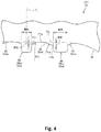
- FIG. 4 shows a cross-section of the tread ring 50 which forms a part of the mold 48 shown in FIG. 3 .
- the contour of the tread-forming surface 56 for shaping the tread surface 22 is schematically represented.
- the right-left direction is the axial direction of the tire 2
- the up-down direction is the radial direction of the tire 2.
- the direction perpendicular to the surface of the sheet of FIG. 4 is the circumferential direction of the tire 2.
- the tread surface 22 of the tire 2 includes the at least two circumferential grooves 42 and the at least three land surfaces 46 which are the outer surfaces of the at least three land portions 44. Therefore, in the mold 48, the tread-forming surface 56 for shaping the tread surface 22 includes at least two projections 66 for forming the at least two circumferential grooves 42, and at least three land surface-forming portions 68 for forming the at least three land surfaces 46.
- the tread-forming surface 56 shown in FIG. 4 includes three projections 66 and four land surface-forming portions 68.
- a projection 66s located on each outer side in the axial direction is a shoulder projection.
- the shoulder projection 66s forms the shoulder circumferential groove 42s of the tire 2.
- a projection 66m located inward of the shoulder projection 66s in the axial direction is a middle projection.
- the middle projection 66m forms the middle circumferential groove 42m of the tire 2.
- a land surface-forming portion 68 located on each outer side in the axial direction is a shoulder land surface-forming portion.
- the shoulder land surface-forming portion 68s forms the shoulder land surface 46s of the tire 2.
- a land surface-forming portion 68m located inward of the shoulder land surface-forming portion 68s in the axial direction is a middle land surface-forming portion.
- the middle land surface-forming portion 68m forms the middle land surface 46m of the tire 2.
- the projection 66 between each shoulder land surface-forming portion 68s and each middle land surface-forming portion 68m is the shoulder projection 66s
- the projection 66 between the right and left middle land surface-forming portions 68m is the middle projection 66m.
- the groove width of each shoulder circumferential groove 42s is larger than the groove width of the middle circumferential groove 42m.
- the width of each shoulder projection 66s for forming the shoulder circumferential groove 42s is larger than the width of the middle projection 66m for forming the middle circumferential groove 42m.
- the shoulder projection 66s is also referred to as wide projection 66w
- the middle projection 66m is also referred to as narrow projection 66n.
- the flow of the unvulcanized rubber that is generated by pressing the projections 66 against the green tire 2r is controlled on the basis of the shapes of the land surface-forming portions 68.
- the circumferential grooves 42 are formed on the cap portion 26 of the tread 4.
- the projections 66 on the tread-forming surface 56 press the cap portion 26.
- the flow of the unvulcanized rubber, for the cap portion 26, generated by pressing the projections 66 against the green tire 2r is controlled on the basis of the shapes of the land surface-forming portions 68.
- the shapes of the land surface-forming portions 68 will be described.
- an alternate long and two short dashes line FBL represents a reference surface of the tread-forming surface 56.
- the reference surface FBL of the tread-forming surface 56 corresponds to the above-described reference surface TBL of the tread surface 22.
- a surface that has a contour represented by at least one circular arc and that is tangent to the at least three land surface-forming portions 68 is the reference surface FBL of the tread-forming surface 56.
- the contour of the reference surface FBL is represented by a plurality of circular arcs aligned in the axial direction which are not shown, the contour of the reference surface FBL is formed such that: one circular arc and another circular arc located adjacent to the one circular arc are tangent to each other at the boundary between both circular arcs; and a circular arc located on the inner side in the axial direction has a radius larger than that of the circular arc located on the outer side.
- the contour of the land surface-forming portion 68 located between two projections 66 will be described on the basis of the contour of the middle land surface-forming portion 68m shown in FIG. 4 .
- the middle land surface-forming portion 68m is located between the shoulder projection 66s and the middle projection 66m.
- the shoulder projection 66s is the wide projection 66w
- the middle projection 66m is the narrow projection 66n.
- the middle land surface-forming portion 68m is the land surface-forming portion 68 located between the wide projection 66w and the narrow projection 66n.
- reference surface FBL of the tread-forming surface 56 is tangent to the at least three land surface-forming portions 68 included in the tread-forming surface 56.
- reference character Pfm represents the tangent point between the reference surface FBL of the tread-forming surface 56 and the land surface-forming portion 68.
- Reference character Pfn represents the end on the narrow projection 66n side of the land surface-forming portion 68. The end Pfn is the boundary between the land surface-forming portion 68 and the outer surface of the narrow projection 66n.
- Reference character Pfw represents the end on the wide projection 66w side of the land surface-forming portion 68. The end Pfw is the boundary between the land surface-forming portion 68 and the wide projection 66w.
- the contour of the land surface-forming portion 68 is represented by a single circular arc that is convex outward.
- an arrow Rrm represents the radius of the circular arc that represents the contour of the land surface-forming portion 68.
- an arrow Rft represents the radius of the circular arc that represents the contour of the reference surface FBL of the tread-forming surface 56 at the middle land surface-forming portion 68m.
- the radius Rrm of the circular arc that represents the contour of the land surface-forming portion 68 is smaller than the radius Rft of the circular arc that represents the contour of the reference surface FBL of the tread-forming surface 56.
- the end Pfn on the narrow projection 66n side of the land surface-forming portion 68 is located inward of the reference surface FBL of the tread-forming surface 56 in the radial direction.
- the end Pfw on the wide projection 66w side of the land surface-forming portion 68 is located radially inward of the reference surface FBL of the tread-forming surface 56.
- the unvulcanized rubber for the cap portion 26 flows toward the portion between two projections 66, that is, the portion where the land portion 44 is to be formed.
- the contour of the land surface-forming portion 68 is formed such that the ends Pfn and Pfw of the land surface-forming portion 68 are located inward of the reference surface FBL of the tread-forming surface 56.
- the volume of the unvulcanized rubber that flows to the portion where the land portion 44 is to be formed is limited, and thus disturbance is less likely to occur in the flow of the unvulcanized rubber pressed against the projections 66.
- the inner surface of the tread 4 is formed in an appropriate shape without having disturbance.
- a drop distance represented as the distance from the reference surface FBL of the tread-forming surface 56 to the end of the land surface-forming portion 68 is preferably not less than 0.01 mm. From the viewpoint of suppressing an increase in ground-contact pressure at a center portion of the land portion 44, the drop distance is preferably not greater than 0.60 mm.
- a double-headed arrow MDN represents the drop distance from the reference surface FBL of the tread-forming surface 56 to the end Pfn on the narrow projection 66n side of the land surface-forming portion 68.
- the drop distance MDN is a narrow-side drop distance.
- a double-headed arrow MDW represents the drop distance from the reference surface FBL of the tread-forming surface 56 to the end Pfw on the wide projection 66w side of the land surface-forming portion 68.
- the drop distance MDW is a wide-side drop distance.
- the volume of the unvulcanized rubber pressed against the wide projection 66w is larger than the volume of the unvulcanized rubber pressed against the narrow projection 66n. In this case, a difference occurs between the flow of the unvulcanized rubber on the wide projection 66w side and the flow of the unvulcanized rubber on the narrow projection 66n side, so that disturbance occurs in the inner surface shape of the tread 4, and the cord reinforcing layer 14 may become wavy depending on the degree of the disturbance.
- the wide-side drop distance MDW is longer than the narrow-side drop distance MDN.
- the volume of the unvulcanized rubber that flows to the portion where the land portion 44 is to be formed is effectively limited on the wide projection 66w side.
- the flow of the unvulcanized rubber on the wide projection 66w side and the flow of the unvulcanized rubber on the narrow projection 66n side are controlled in a well-balanced manner, and thus disturbance is less likely to occur in the flow of the unvulcanized rubber.
- the inner surface of the tread 4 is formed in an appropriate shape without having disturbance.
- the right-left direction corresponds to the axial direction of the tire 2.
- the up-down direction corresponds to the circumferential direction of the tire 2.
- the ground-contact surface shape is obtained by tracing the contour of each land portion 44 on a ground-contact surface obtained by applying a load equal to the normal load to the tire 2 in the normal state and pressing the tire 2 against a road surface, using a tire ground-contact shape measuring device (not shown).
- a tire ground-contact shape measuring device (not shown).
- the tire 2 is placed such that the axial direction thereof is parallel to the road surface, and the above load is applied to the tire 2 in a direction perpendicular to the road surface.
- the road surface is formed as a flat surface.
- the tire 2 is pressed against the flat road surface.
- the ground-contact surface shape, shown in FIG. 9 of the tire produced by the conventional mold is also obtained in the same manner.
- the outer edge in the circumferential direction of the middle land portion 44m located between each shoulder circumferential groove 42s and the middle circumferential groove 42m does not have a shape that is convex inward as in the outer edge in the circumferential direction of each middle land portion confirmed for the tire produced by the conventional mold and shown in FIG. 9 , but has a shape that bulges outward.
- the area of the ground-contact surface is clearly increased, so that the tire 2 can more sufficiently come into contact with a road surface than the tire produced by the conventional mold. With the mold 48, the steering stability of the tire 2 can be further improved.
- the vertical axis represents ground-contact pressure
- the horizontal axis represents a position in the ground-contact width direction of the ground-contact surface.
- the right side shows a ground-contact pressure distribution of the shoulder land portion 44s
- the left side shows a ground-contact pressure distribution of the middle land portion 44m.
- the ground-contact pressure distribution is obtained by applying a load equal to the normal load to the tire 2 in the normal state and pressing the tire 2 against a road surface, using a tire ground-contact pressure measuring device (not shown).
- a tire ground-contact pressure measuring device (not shown).
- the tire 2 is placed such that the axial direction thereof is parallel to the road surface, and the above load is applied to the tire 2 in a direction perpendicular to the road surface.
- the road surface is formed as a flat surface.
- a ground-contact pressure distribution, shown in FIG. 10 of the tire produced by the conventional mold is obtained in the same manner.
- the ground-contact pressure distribution indicated by a dotted line is the ground-contact pressure distribution of the tire produced by the conventional mold.
- the increase in ground-contact pressure at each edge of the middle land portion 44m is suppressed as compared to the increase in ground-contact pressure at each edge of the middle land portion confirmed for the tire produced by the conventional mold and shown in FIG. 10 .
- the ground-contact pressure difference in the middle land portion 44m is reduced to about 50 kPa. The local increase in ground-contact pressure is clearly suppressed, so that the wear resistance of the tire 2 can be further improved with the mold 48.
- the ground-contact surface shape and the ground-contact pressure distribution of the tire 2 can be made appropriate, so that improvement of the steering stability and the wear resistance of the tire 2 can be achieved.
- the groove width of each circumferential groove 42 provided on the tread 4 of the tire 2 is not less than 9 mm. Therefore, in the mold 48, the width of each projection 66 for shaping the circumferential groove 42 is set so as to be not less than 9 mm.
- the width of the projection 66 is represented as the distance from one corner to the other corner at the base of the projection 66. In the case where the corners of the projection 66 are rounded, the width of the projection 66 is specified on the basis of virtual corners obtained on the assumption that the corners are not rounded.
- a double-headed arrow MRN represents the width of the narrow projection 66n.
- a double-headed arrow MRW represents the width of the wide projection 66w.
- the wide-side drop distance MDW is longer than the narrow-side drop distance MDN
- the narrow-side drop distance MDN is not less than 0.01 mm
- the wide-side drop distance MDW is not greater than 0.3 mm. Accordingly, the flow of the unvulcanized rubber on the wide projection 66w side and the flow of the unvulcanized rubber on the narrow projection 66n side are controlled in a well-balanced manner, and thus disturbance is less likely to occur in the flow of the unvulcanized rubber.
- the inner surface of the tread 4 is formed in an appropriate shape without having disturbance.
- the ground-contact surface shape and the ground-contact pressure distribution of the tire 2 can be made appropriate, so that improvement of the steering stability and the wear resistance of the tire 2 can be achieved.
- the narrow-side drop distance MDN satisfies the following formula (MN1) represented using the width MRN of the narrow projection 66n
- the wide-side drop distance MDW satisfies the following formula (MW1) represented using the width MRW of the wide projection 66w. 0.0344 ⁇ MRW ⁇ 0.4094 ⁇ MDW ⁇ 0.0344 ⁇ MRW ⁇ 0.1094 0.0344 ⁇ MRN ⁇ 0.4094 ⁇ MDN ⁇ 0.0344 ⁇ MRN ⁇ 0.1094
- the flow of the unvulcanized rubber on the wide projection 66w side and the flow of the unvulcanized rubber on the narrow projection 66n side are controlled in a well-balanced manner, and thus disturbance is less likely to occur in the flow of the unvulcanized rubber.
- the inner surface of the tread 4 is formed in an appropriate shape without having disturbance.
- the ground-contact surface shape and the ground-contact pressure distribution of the tire 2 can be made appropriate, so that improvement of the steering stability and the wear resistance of the tire 2 can be achieved.
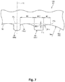
- FIG. 7 shows a cross-section of the tread ring 50 which forms a part of the mold 48 shown in FIG. 3 .
- the contour of the tread-forming surface 56 for shaping the tread surface 22, which is the same as in FIG. 4 is schematically represented.
- the contour of the land surface-forming portion 68 located on the outer side in the axial direction, that is, the shoulder land surface-forming portion 68s, will be described on the basis of the contour of the shoulder land surface-forming portion 68s shown in FIG. 7 .
- the shoulder land surface-forming portion 68s is the land surface-forming portion 68 located on the outer side in the axial direction among the at least three land surface-forming portions 68 included in the tread-forming surface 56.
- the land surface-forming portion 68 located inward of the shoulder land surface-forming portion 68s in the axial direction is the middle land surface-forming portion 68m, and the projection 66 between the shoulder land surface-forming portion 68s and the middle land surface-forming portion 68m is the shoulder projection 66s.
- reference character Pfb represents the tangent point between the shoulder land surface-forming portion 68s and the reference surface FBL of the tread-forming surface 56 on the shoulder projection 66s side.
- Reference character Pfs represents the end on the shoulder projection 66s side of the shoulder land surface-forming portion 68s.
- the contour of the portion from the end Pfs on the shoulder projection 66s side of the shoulder land surface-forming portion 68s to the reference position Pfb is represented by a single circular arc that is convex outward.
- an arrow Rrs represents the radius of the circular arc that represents the contour of the shoulder land surface-forming portion 68s.
- the contour configuration of the shoulder land surface-forming portion 68s is not clear, when the center position between the reference position Pfb and the end Pfs is specified, a circular arc passing through the reference position Pfb, the center position, and the end Pfs is drawn, and the maximum value of the distance between this circular arc and the contour is not greater than 0.03 mm, it is determined that the contour of the portion from the end Pfs on the shoulder projection 66s side of the shoulder land surface-forming portion 68s to the reference position Pfb is represented by a single circular arc that is convex outward.
- an arrow Rms represents the radius of the circular arc that represents the contour of the reference surface FBL of the tread-forming surface 56 at the shoulder land surface-forming portion 68s.
- the radius Rrs of the circular arc that represents the contour of the shoulder land surface-forming portion 68s is smaller than the radius Rms of the circular arc that represents the contour of the reference surface FBL of the tread-forming surface 56.
- the end Pfs on the shoulder projection 66s side of the shoulder land surface-forming portion 68s is located inward of the reference surface FBL of the tread-forming surface 56 in the radial direction.
- the unvulcanized rubber for the cap portion 26 flows toward the portion that is axially outward of each shoulder projection 66s, that is, the portion where the shoulder land portion 44s is to be formed.
- the contour of the shoulder land surface-forming portion 68s is formed such that the end Pfs of the shoulder land surface-forming portion 68s is located inward of the reference surface FBL of the tread-forming surface 56.
- the volume of the unvulcanized rubber that flows to the portion where the shoulder land portion 44s is to be formed is limited, and thus disturbance is less likely to occur in the flow of the unvulcanized rubber pressed against the shoulder projection 66s.
- the inner surface of the tread 4 is formed in an appropriate shape without having disturbance.
- the outer edge in the circumferential direction of each shoulder land portion 44s does not have a shape that is convex inward as in the outer edge in the circumferential direction of each shoulder land portion confirmed for the tire produced by the conventional mold and shown in FIG. 9 , but has a shape that bulges outward.
- the area of the ground-contact surface is clearly increased, so that the tire 2 can more sufficiently come into contact with a road surface than the tire produced by the conventional mold. With the mold 48, the steering stability of the tire 2 can be further improved.
- the increase in ground-contact pressure at each edge of the shoulder land portion 44s is suppressed as compared to the increase in ground-contact pressure at each edge of the shoulder land portion confirmed for the tire produced by the conventional mold and shown in FIG. 10 .
- the ground-contact pressure difference in the shoulder land portion 44s is reduced to about 150 kPa. The local increase in ground-contact pressure is clearly suppressed, so that the wear resistance of the tire 2 can be further improved with the mold 48.
- the ground-contact surface shape and the ground-contact pressure distribution of the tire 2 can be made appropriate, so that improvement of the steering stability and the wear resistance of the tire 2 can be achieved.
- a double-headed arrow MY represents the width of the middle land surface-forming portion 68m.
- the width MY is represented as the distance from the corner on the middle land surface-forming portion 68m side of the middle projection 66m to the corner on the middle land surface-forming portion 68m side of the shoulder projection 66s.
- a double-headed arrow MZ represents the distance from the end Pfs on the shoulder projection 66s side of the shoulder land surface-forming portion 68s to the reference position Pfb.
- the distance MZ is represented as the distance from the corner on the shoulder land surface-forming portion 68s side of the shoulder projection 66s to the reference position Pfb.
- the distance MZ from the end Pfs on the shoulder projection 66s side of the shoulder land surface-forming portion 68s to the reference position Pfb preferably satisfies the following formula (MS1).
- MS1 the width of the middle land surface-forming portion 68m
- MZ the distance from the end Pfs on the shoulder projection 66s side of the shoulder land surface-forming portion 68s to the reference position Pfb preferably satisfies the following formula (MS1).
- MS1 MY / 2 ⁇ 5 ⁇ MZ ⁇ MY / 2 + 5
- a double-headed arrow MDS represents a drop distance of the shoulder land surface-forming portion 68s.
- the drop distance MDS is represented as the distance from the reference surface FBL of the tread-forming surface 56 to the end Pfs of the shoulder land surface-forming portion 68s.
- the drop distance MDS represented as the distance from the reference surface FBL of the tread-forming surface 56 to the end Pfs of the shoulder land surface-forming portion 68s is preferably not less than 0.05 mm. From the viewpoint of suppressing an increase in ground-contact pressure at a center portion of the shoulder land portion 44s, the drop distance MDS is preferably not greater than 0.60 mm.
- a double-headed arrow MRZ represents the width of the shoulder projection 66s.
- the width MRZ of the shoulder projection 66s is represented as the distance from one corner to the other corner at the base of the shoulder projection 66s.
- the flow of the unvulcanized rubber is controlled on the basis of the contours of the shoulder land surface-forming portions 68s and the land surface-forming portions 68 each located between two projections 66.
- the flow of the unvulcanized rubber may be controlled on the basis of the contours of the land surface-forming portions 68 each located between two projections 66, and, in the case where the disturbance of the inner surface occurs at shoulder portions of the tread 4, the flow of the unvulcanized rubber may be controlled on the basis of the contours of the shoulder land surface-forming portions 68s.
- the flow of the unvulcanized rubber is preferably controlled on the basis of the contours of the shoulder land surface-forming portions 68s and the land surface-forming portions 68 each located between two projections 66.
- the tire 2 shown in FIG. 1 is produced using the above-described mold 48 having the tread-forming surface 56. Next, the contour of the tread surface 22 shaped by the tread-forming surface 56 will be described.
- the contour of the land surface 46 located between two circumferential grooves 42 will be described on the basis of the contour of the middle land surface 46m shown in FIG. 2 .
- the middle land surface 46m is located between the shoulder circumferential groove 42s and the middle circumferential groove 42m.
- the shoulder circumferential groove 42s is the wide circumferential groove 42w
- the middle circumferential groove 42m is the narrow circumferential groove 42n.
- the middle land surface 46m is the land surface 46 located between the wide circumferential groove 42w and the narrow circumferential groove 42n.
- reference surface TBL of the tread surface 22 is tangent to the at least three land surfaces 46 included in the tread surface 22.
- reference character Ptm represents the tangent point between the reference surface TBL of the tread surface 22 and the land surface 46.
- Reference character Ptn represents the end on the narrow circumferential groove 42n side of the land surface 46. The end Ptn is the boundary between the land surface 46 and the narrow circumferential groove 42n.
- Reference character Ptw represents the end on the wide circumferential groove 42w side of the land surface 46. The end Ptw is the boundary between the land surface 46 and the wide circumferential groove 42w.
- the contour of the land surface 46 is represented by a single circular arc that is convex outward.
- an arrow Rst represents the radius of the circular arc that represents the contour of the land surface 46.
- the contour configuration of the land surface 46 is not clear, when a circular arc passing through the boundary Ptn, the tangent point Ptm, and the boundary Ptw is drawn and the maximum value of the distance between this circular arc and the contour is not greater than 0.03 mm, it is determined that the contour of the land surface 46 is represented by a single circular arc that is convex outward.
- an arrow Rmt represents the radius of the circular arc that represents the contour of the reference surface TBL of the tread surface 22 at the middle land surface 46m.
- the radius Rst of the circular arc that represents the contour of the land surface 46 is smaller than the radius Rmt of the circular arc that represents the contour of the reference surface TBL of the tread surface 22.
- the end Ptn on the narrow circumferential groove 42n side of the land surface 46 is located inward of the reference surface TBL of the tread surface 22 in the radial direction.
- the end Ptw on the wide circumferential groove 42w side of the land surface 46 is located radially inward of the reference surface TBL of the tread surface 22.
- the unvulcanized rubber for the cap portion 26 flows toward the portion between two circumferential grooves 42, that is, the portion where the land portion 44 is to be formed.
- the contour of the land surface 46 is formed such that the ends Ptn and Ptw of the land surface 46 are located inward of the reference surface TBL of the tread surface 22.
- the volume of the unvulcanized rubber that flows to the portion where the land portion 44 is to be formed is limited, and thus disturbance is less likely to occur in the flow of the unvulcanized rubber pressed against the projections 66.
- the inner surface of the tread 4 is formed in an appropriate shape without having disturbance.
- the drop distance represented as the distance from the reference surface TBL of the tread surface 22 to the end of the land surface 46 is preferably not less than 0.01 mm. From the viewpoint of suppressing an increase in ground-contact pressure at the center portion of the land portion 44, the drop distance is preferably not greater than 0.60 mm.
- a double-headed arrow TDN represents the drop distance from the reference surface TBL of the tread surface 22 to the end Ptn on the narrow circumferential groove 42n side of the land surface 46.
- the drop distance TDN is a narrow-side drop distance.
- a double-headed arrow TDW represents the drop distance from the reference surface TBL of the tread surface 22 to the end Ptw on the wide circumferential groove 42w side of the land surface 46.
- the drop distance TDW is a wide-side drop distance.
- the volume of the unvulcanized rubber pressed against the wide projection 66w is larger than the volume of the unvulcanized rubber pressed against the narrow projection 66n. In this case, a difference occurs between the flow of the unvulcanized rubber on the wide projection 66w side and the flow of the unvulcanized rubber on the narrow projection 66n side, so that disturbance occurs in the inner surface shape of the tread 4, and the cord reinforcing layer 14 may become wavy depending on the degree of the disturbance.
- the wide-side drop distance TDW is longer than the narrow-side drop distance TDN.
- the volume of the unvulcanized rubber that flows to the portion where the land portion 44 is to be formed is effectively limited on the wide projection 66w side.
- the flow of the unvulcanized rubber on the wide projection 66w side and the flow of the unvulcanized rubber on the narrow projection 66n side are controlled in a well-balanced manner, and thus disturbance is less likely to occur in the flow of the unvulcanized rubber.
- the inner surface of the tread 4 is formed in an appropriate shape without having disturbance.
- the outer edge in the circumferential direction of the middle land portion 44m located between each shoulder circumferential groove 42s and the middle circumferential groove 42m does not have a shape that is convex inward as in the outer edge in the circumferential direction of each middle land portion confirmed for the tire produced by the conventional mold and shown in FIG. 9 , but has a shape that bulges outward.
- the area of the ground-contact surface is clearly increased, so that the tire 2 can more sufficiently come into contact with a road surface than the tire produced by the conventional mold.
- the steering stability of the tire 2 can be further improved.
- the increase in ground-contact pressure at each edge of the middle land portion 44m is suppressed as compared to the increase in ground-contact pressure at each edge of the middle land portion confirmed for the tire produced by the conventional mold and shown in FIG. 10 .
- the local increase in ground-contact pressure is clearly suppressed, so that the wear resistance of the tire 2 can be further improved.
- the wide-side drop distance TDW is longer than the narrow-side drop distance TDN
- the narrow-side drop distance TDN is not less than 0.01 mm
- the wide-side drop distance TDW is not greater than 0.3 mm. Accordingly, the flow of the unvulcanized rubber on the wide projection 66w side and the flow of the unvulcanized rubber on the narrow projection 66n side are controlled in a well-balanced manner, and thus disturbance is less likely to occur in the flow of the unvulcanized rubber.
- the inner surface of the tread 4 is formed in an appropriate shape without having disturbance.
- an appropriate ground-contact surface shape and an appropriate ground-contact pressure distribution are obtained, and thus improvement of steering stability and wear resistance can be achieved.
- a double-headed arrow TRN represents the groove width of the narrow circumferential groove 42n.
- a double-headed arrow TRW represents the groove width of the wide circumferential groove 42w.
- the narrow-side drop distance TDW satisfies the following formula (TN1) represented using the groove width TRN of the narrow circumferential groove 42n
- the wide-side drop distance TDW satisfies the following formula (TW1) represented using the groove width TRW of the wide circumferential groove 42w. 0.0344 ⁇ TRW ⁇ 0.4094 ⁇ TDW ⁇ 0.0344 ⁇ TRW ⁇ 0.1094 0.0344 ⁇ TRN ⁇ 0.4094 ⁇ TDN ⁇ 0.0344 ⁇ TRN ⁇ 0.1094
- the flow of the unvulcanized rubber on the wide projection 66w side and the flow of the unvulcanized rubber on the narrow projection 66n side are controlled in a well-balanced manner, and thus disturbance is less likely to occur in the flow of the unvulcanized rubber.
- the inner surface of the tread 4 is formed in an appropriate shape without having disturbance.
- an appropriate ground-contact surface shape and an appropriate ground-contact pressure distribution are obtained, and thus improvement of steering stability and wear resistance can be achieved.
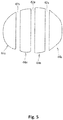
- FIG. 8 shows a cross-section of a portion of the tread 4 shown in FIG. 1 .
- the contour of the tread surface 22 that is the same as in FIG. 2 is schematically represented.
- the contour of the land surface 46 located on the outer side in the axial direction, that is, the shoulder land surface 46s, will be described on the basis of the contour of the shoulder land surface 46s shown in FIG. 8 .
- the shoulder land surface 46s is the land surface 46 located on the outer side in the axial direction among the at least three land surfaces 46 included in the tread surface 22.
- the land surface 46 located inward of the shoulder land surface 46s in the axial direction is the middle land surface 46m, and the circumferential groove 42 between the shoulder land surface 46s and the middle land surface 46m is the shoulder circumferential groove 42s.
- reference character Ptb represents the tangent point between the shoulder land surface 46s and the reference surface TBL of the tread surface 22 on the shoulder circumferential groove 42s side.
- Reference character Pts represents the end on the shoulder circumferential groove 42s side of the shoulder land surface 46s.
- the contour configuration of the shoulder land surface 46s is not clear, when the center position between the reference position Ptb and the end Pts is specified, a circular arc passing through the reference position Ptb, the center position, and the end Pts is drawn, and the maximum value of the distance between this circular arc and the contour is not greater than 0.03 mm, it is determined that the contour of the portion from the end Pts on the shoulder circumferential groove 42s side of the shoulder land surface 46s to the reference position Ptb is represented by a single circular arc that is convex outward.
- an arrow Rts represents the radius of the circular arc that represents the contour of the reference surface TBL of the tread surface 22 at the shoulder land surface 46s.
- the radius Rss of the circular arc that represents the contour of the shoulder land surface 46s is smaller than the radius Rts of the circular arc that represents the contour of the reference surface TBL of the tread surface 22.
- the end Pts on the shoulder circumferential groove 42s side of the shoulder land surface 46s is located inward of the reference surface TBL of the tread surface 22 in the radial direction.
- the unvulcanized rubber for the cap portion 26 flows toward the portion that is axially outward of each shoulder projection 66s, that is, the portion where the shoulder land portion 44s is to be formed.
- the contour of the shoulder land surface 46s is formed such that the end Pts of the shoulder land surface 46s is located inward of the reference surface TBL of the tread surface 22.
- the volume of the unvulcanized rubber that flows to the portion where the shoulder land portion 44s is to be formed is limited, and thus disturbance is less likely to occur in the flow of the unvulcanized rubber pressed against the shoulder projection 66s.
- the inner surface of the tread 4 is formed in an appropriate shape without having disturbance.
- the outer edge in the circumferential direction of each shoulder land portion 44s does not have a shape that is convex inward as in the outer edge in the circumferential direction of each shoulder land portion confirmed for the tire produced by the conventional mold and shown in FIG. 9 , but has a shape that bulges outward.
- the area of the ground-contact surface is clearly increased, so that the tire 2 can more sufficiently come into contact with a road surface than the tire produced by the conventional mold.
- the steering stability of the tire 2 can be further improved.
- the increase in ground-contact pressure at each edge of the shoulder land portion 44s is suppressed as compared to the increase in ground-contact pressure at each edge of the shoulder land portion confirmed for the tire produced by the conventional mold and shown in FIG. 10 .
- the local increase in ground-contact pressure is clearly suppressed, so that the wear resistance of the tire 2 can be further improved.
- a double-headed arrow TY represents the width of the middle land surface 46m.
- the width TY is represented as the distance from one edge of the middle land portion 44m to the other edge of the middle land portion 44m.
- a double-headed arrow TZ represents the distance from the end Pts on the shoulder circumferential groove 42s side of the shoulder land surface 46s to the reference position Ptb.
- the distance TZ is represented as the distance from the edge of the shoulder land portion 44s to the reference position Ptb.
- the distance TZ from the end Pts on the shoulder circumferential groove 42s side of the shoulder land surface 46s to the reference position Ptb preferably satisfies the following formula (TS1).
- TY / 2 ⁇ 5 ⁇ TZ ⁇ TY / 2 + 5 Accordingly, the volume of the unvulcanized rubber that flows to the portion where the shoulder land portion 44s is to be formed is limited, and thus disturbance is less likely to occur in the flow of the unvulcanized rubber pressed against the shoulder projection 66s.
- the inner surface of the tread 4 is formed in an appropriate shape without having disturbance.
- a double-headed arrow TDS represents a drop distance of the shoulder land surface 46s.
- the drop distance TDS is represented as the distance from the reference surface TBL of the tread surface 22 to the end Pts of the shoulder land surface 46s.
- the drop distance TDS represented as the distance from the reference surface TBL of the tread surface 22 to the end Pts of the shoulder land surface 46s is preferably not less than 0.05 mm. From the viewpoint of suppressing an increase in ground-contact pressure at the center portion of the shoulder land portion 44s, the drop distance TDS is preferably not greater than 0.60 mm.
- a double-headed arrow TRZ represents the groove width of the shoulder circumferential groove 42s.
- the groove width TRZ of the shoulder circumferential groove 42s is represented as the distance from the edge on the shoulder circumferential groove 42s side of the middle land portion 44m to the edge of the shoulder land portion 44s.
- the flow of the unvulcanized rubber is controlled on the basis of the contours of each shoulder land surface 46s and the land surfaces 46 each located between two circumferential grooves 42.
- the flow of the unvulcanized rubber may be controlled on the basis of the contours of the land surfaces 46 each located between two circumferential grooves 42, and, in the case where disturbance of the inner surface occurs at the shoulder portions of the tread 4, the flow of the unvulcanized rubber may be controlled on the basis of the contour of each shoulder land surface 46s.
- the flow of the unvulcanized rubber is preferably controlled on the basis of the contours of each shoulder land surface 46s and the land surfaces 46 each located between two circumferential grooves 42.
- the ground-contact surface shape and the ground-contact pressure distribution of the tire 2 can be made appropriate.
- an appropriate ground-contact surface shape and an appropriate ground-contact pressure distribution are obtained, and thus steering stability and wear resistance can be improved.
- the present invention exhibits a remarkable effect in the case where the unvulcanized rubber for the cap portion 26 has a Mooney viscosity of not less than 80.
- the Mooney viscosity means a Mooney viscosity ML 1+4 (100°C) and is measured according to JIS K6300-1.
Landscapes
- Engineering & Computer Science (AREA)
- Mechanical Engineering (AREA)
- Moulds For Moulding Plastics Or The Like (AREA)
- Tires In General (AREA)
- Heating, Cooling, Or Curing Plastics Or The Like In General (AREA)
Abstract
Description
- The present invention relates a tire mold, a production method for a tire, and a tire.
- A tire is obtained by pressurizing and heating a tire in an uncrosslinked state (hereinafter, green tire) within a mold. A plurality of circumferential grooves are formed on the tread of the tire so as to be aligned in the axial direction, whereby land portions are formed therein. In order to form the circumferential grooves, projections corresponding to the circumferential grooves are provided on a tread-forming surface of the mold. By pressing the green tire against the projections, the circumferential grooves are formed on the tread.
- The tire includes, for example, a belt including a large number of aligned cords, on the radially inner side of the tread. Various measures are taken in the production of tires such that the belt does not become wavy as a result of pressing the green tire against the projections (for example, Japanese Laid-Open Patent Publication No.
2014-61602 - When the green tire is pressed against the projections, a part of a rubber composition in an unvulcanized state (hereinafter, unvulcanized rubber) pressed by the projections flows into portions where the land portions are to be formed. At this time, if the unvulcanized rubber does not flow easily, disturbance may occur in the inner surface shape of the tread. In particular, in the case of forming a wide circumferential groove having a groove width of not less than 9 mm on the tread, the volume of the unvulcanized rubber pressed against the projection is large, so that it is difficult to control the thickness of the tread, and the belt may become wavy.
-
FIG. 9 shows a ground-contact surface shape of a tire (size = 205/55R16) in which disturbance has occurred in the inner surface shape of a tread.FIG. 9 shows the contour of each land portion included in the ground-contact surface.FIG. 10 shows a ground-contact pressure distribution of the tire. InFIG. 10 , the right side shows a ground-contact pressure distribution of a shoulder land portion, and the left side shows a ground-contact pressure distribution of a middle land portion. - As shown in
FIG. 9 , in the ground-contact surface shape, the outer edge in the circumferential direction of each land portion has a shape that is convex inward. As shown inFIG. 10 , it is confirmed that the ground-contact pressure is locally increased at the edge of each land portion. Specifically, a ground-contact pressure difference of about 200 kPa is confirmed in the middle land portion, and a ground-contact pressure difference of about 250 kPa is confirmed in the shoulder land portion. The disturbance in the inner surface shape of the tread influences the ground-contact surface shape and the ground-contact pressure distribution of the tire. In other words, if the disturbance in the inner surface shape of the tread in the tire can be suppressed, the tire can be more sufficiently brought into contact with a road surface, so that it is expected that steering stability can be further improved. In this case, a local increase in ground-contact pressure is also suppressed, so that it is also expected that wear resistance can be improved. - The present invention has been made in view of the above circumstances, and an object of the present invention is to provide a tire mold and a production method for a tire that are capable of making a ground-contact surface shape and a ground-contact pressure distribution appropriate, and a tire having a ground-contact surface shape and a ground-contact pressure distribution that are made appropriate.
- A tire mold according to an aspect of the present invention is a mold used for producing a tire including a tread having a tread surface that comes into contact with a road surface, at least two circumferential grooves having a groove width of not less than 9 mm being formed on the tread so as to extend in a circumferential direction, thereby forming at least three land portions in the tread, the tread surface including the at least two circumferential grooves and at least three land surfaces that are outer surfaces of the at least three land portions, the mold including a tread-forming surface for shaping the tread surface. The tread-forming surface includes at least two projections for forming the at least two circumferential grooves, and at least three land surface-forming portions for forming the at least three land surfaces. A contour of a land surface-forming portion located between two projections among the at least three land surface-forming portions is represented by a single circular arc that is convex outward. In a case where, of the two projections, one projection is a wide projection having a larger width than the other projection, and the other projection is a narrow projection having a smaller width than the one projection, when a surface that has a contour represented by at least one circular arc and that is tangent to the at least three land surface-forming portions is defined as a reference surface of the tread-forming surface, a wide-side drop distance MDW that is a distance from the reference surface of the tread-forming surface to an end on the wide projection side of the land surface-forming portion is longer than a narrow-side drop distance MDN that is a distance from the reference surface of the tread-forming surface to an end on the narrow projection side of the land surface-forming portion.
- Preferably, in the tire mold,
in a case where a width of each projection is not less than 9 mm and not greater than 12 mm, the narrow-side drop distance MDN is not less than 0.01 mm, and the wide-side drop distance MDW is not greater than 0.3 mm, and
in a case where the width of each projection is greater than 12 mm, the narrow-side drop distance MDN satisfies the following formula (MN1) represented using a width MRN of the narrow projection, and the wide-side drop distance MDW satisfies the following formula (MW1) represented using a width MRW of the wide projection.

- A tire mold according to an aspect of the present invention is a mold used for producing a tire including a tread having a tread surface that comes into contact with a road surface, at least two circumferential grooves having a groove width of not less than 9 mm being formed on the tread so as to extend in a circumferential direction, thereby forming at least three land portions in the tread, the tread surface including the at least two circumferential grooves and at least three land surfaces that are outer surfaces of the at least three land portions, the mold including a tread-forming surface for shaping the tread surface. The tread-forming surface includes at least two projections for forming the at least two circumferential grooves, and at least three land surface-forming portions for forming the at least three land surfaces. Among the at least three land surface-forming portions, a land surface-forming portion located on each outer side in an axial direction is a shoulder land surface-forming portion, a land surface-forming portion located inward of the shoulder land surface-forming portion is a middle land surface-forming portion, and a projection between the shoulder land surface-forming portion and the middle land surface-forming portion is a shoulder projection. When a surface that has a contour represented by at least one circular arc and that is tangent to the at least three land surface-forming portions is defined as a reference surface of the tread-forming surface, and a tangent point between the shoulder land surface-forming portion and the reference surface of the tread-forming surface on the shoulder projection side is defined as a reference position, a contour of a portion from an end on the shoulder projection side of the shoulder land surface-forming portion to the reference position is represented by a single circular arc.
- Preferably, in the tire mold, when a width of the middle land surface-forming portion is denoted by MY, a distance MZ from the end on the shoulder projection side to the reference position satisfies the following formula (MS1).

- Preferably, in the tire mold, a shoulder-side drop distance MDS that is a distance from the reference surface of the tread-forming surface to the end on the shoulder projection side of the shoulder land surface-forming portion is not less than 0.05 mm and not greater than 0.6 mm.
- Preferably, in the tire mold, the tread includes a cap portion including the tread surface, and an unvulcanized rubber for the cap portion has a Mooney viscosity of not less than 80.
- A production method for a tire according to an aspect of the present invention includes a step of pressurizing and heating a green tire using any of the tire molds described above.
- A tire according to an aspect of the present invention includes a tread having a tread surface that comes into contact with a road surface, at least two circumferential grooves having a groove width of not less than 9 mm are formed on the tread so as to extend in a circumferential direction, thereby forming at least three land portions in the tread, and the tread surface includes the at least two circumferential grooves and at least three land surfaces that are outer surfaces of the at least three land portions. In the tire, a contour of a land surface located between two circumferential grooves among the at least three land surfaces is represented by a single circular arc that is convex outward. In a case where, of the two circumferential grooves, one circumferential groove is a wide circumferential groove having a larger groove width than the other circumferential groove, and the other circumferential groove is a narrow circumferential groove having a smaller groove width than the one circumferential groove, when a surface that has a contour represented by at least one circular arc and that is tangent to the at least three land surfaces is defined as a reference surface of the tread surface, a wide-side drop distance TDW that is a distance from the reference surface of the tread surface to an end on the wide circumferential groove side of the land surface is longer than a narrow-side drop distance TDN that is a distance from the reference surface of the tread surface to an end on the narrow circumferential groove side of the land surface.
- A tire according to another aspect of the present invention includes a tread having a tread surface that comes into contact with a road surface, at least two circumferential grooves having a groove width of not less than 9 mm are formed on the tread so as to extend in a circumferential direction, thereby forming at least three land portions in the tread, and the tread surface includes the at least two circumferential grooves and at least three land surfaces that are outer surfaces of the at least three land portions. In the tire, among the at least three land surfaces, a land surface located on each outer side in an axial direction is a shoulder land surface, a land surface located inward of the shoulder land surface is a middle land surface, and a circumferential groove between the shoulder land surface and the middle land surface is a shoulder circumferential groove. When a surface that has a contour represented by at least one circular arc and that is tangent to the at least three land surfaces is defined as a reference surface of the tread surface, and a tangent point between the shoulder land surface and the reference surface of the tread surface on the shoulder circumferential groove side is defined as a reference position, a contour of a portion from an end on the shoulder circumferential groove side of the shoulder land surface to the reference position is represented by a single circular arc.
- With the tire mold and the production method for a tire according to the present invention, the ground-contact surface shape and the ground-contact pressure distribution of a tire can be made appropriate. In a tire obtained by the tire mold and the production method for a tire, an appropriate ground-contact surface shape and an appropriate ground-contact pressure distribution are obtained, and thus steering stability and wear resistance can be improved.
-
-
FIG. 1 is a cross-sectional view showing a part of a pneumatic tire according to an embodiment of the present invention; -
FIG. 2 is a cross-sectional view showing a part of the tire shown inFIG. 1 ; -
FIG. 3 is a cross-sectional view showing a part of a tire mold according to an embodiment of the present invention; -
FIG. 4 is a cross-sectional view showing a part of the mold shown inFIG. 3 ; -
FIG. 5 is a schematic diagram showing an example of a ground-contact surface shape of a tire produced by a mold having the configuration shown inFIG. 4 ; -
FIG. 6 is a graph showing an example of a ground-contact pressure distribution of the tire produced by the mold having the configuration shown inFIG. 4 ; -
FIG. 7 is a cross-sectional view showing a part of the mold shown inFIG. 3 ; -
FIG. 8 is a cross-sectional view showing a part of the tire shown inFIG. 1 ; -
FIG. 9 is a schematic diagram showing an example of a ground-contact surface shape of a tire produced by a conventional mold; and -
FIG. 10 is a graph showing an example of a ground-contact pressure distribution of the tire produced by the conventional mold. - Hereinafter, the present invention will be described in detail based on preferred embodiments with appropriate reference to the drawings.
- In the present invention, a state where a tire is mounted on a normal rim, the internal pressure of the tire is adjusted to a normal internal pressure, and no load is applied to the tire is referred to as a normal state. In the present invention, unless otherwise specified, the dimensions and angles of each component of the tire are measured in the normal state.
- The normal rim means a rim specified in a standard on which the tire is based. The "standard rim" in the JATMA standard, the "Design Rim" in the TRA standard, and the "Measuring Rim" in the ETRTO standard are normal rims.
- The normal internal pressure means an internal pressure specified in the standard on which the tire is based. The "highest air pressure" in the JATMA standard, the "maximum value" recited in "TIRE LOAD LIMITS AT VARIOUS COLD INFLATION PRESSURES" in the TRA standard, and the "INFLATION PRESSURE" in the ETRTO standard are normal internal pressures. The normal internal pressure of a tire for a passenger car is, for example, 180 kPa.
- A normal load means a load specified in the standard on which the tire is based. The "maximum load capacity" in the JATMA standard, the "maximum value" recited in the "TIRE LOAD LIMITS AT VARIOUS COLD INFLATION PRESSURES" in the TRA standard, and the "LOAD CAPACITY" in the ETRTO standard are normal loads. The normal load of a tire for a passenger car is, for example, a load corresponding to 88% of the above load.
-
FIG. 1 shows a part of a pneumatic tire 2 (hereinafter, sometimes referred to simply as "tire 2") according to an embodiment of the present invention. Thetire 2 is mounted to a passenger car. -
FIG. 1 shows a part of a cross-section of thetire 2 along a plane including the rotation axis of thetire 2. InFIG. 1 , the right-left direction is the axial direction of thetire 2, and the up-down direction is the radial direction of thetire 2. The direction perpendicular to the surface of the sheet ofFIG. 1 is the circumferential direction of thetire 2. InFIG. 1 , an alternate long and short dash line CL represents the equator plane of thetire 2. - The
tire 2 includes atread 4, a pair ofsidewalls 6, a pair of clinches 8, a pair ofbeads 10, acarcass 12, acord reinforcing layer 14, a pair ofchafers 16, aninner liner 18, and a pair of rubber reinforcing layers 20. - A part of the outer surface of the
tread 4 comes into contact with a road surface. Thetread 4 has atread surface 22 that comes into contact with a road surface. Thetread 4 is located outward of thecord reinforcing layer 14 in the radial direction. - The
tread 4 includes abase portion 24 and acap portion 26. Thebase portion 24 forms a radially inner portion of thetread 4. Thebase portion 24 is formed from a crosslinked rubber for which heat generation properties are taken into consideration. Thecap portion 26 is located radially outward of thebase portion 24. In thetire 2, thecap portion 26 comes into contact with a road surface. The outer surface of thecap portion 26 includes the above-describedtread surface 22. Thecap portion 26 is formed from a crosslinked rubber for which wear resistance and grip performance are taken into consideration. Thetread 4 may be composed of only thecap portion 26. - Each
sidewall 6 extends from an end of thetread 4 inwardly in the radial direction along thecarcass 12. Thesidewall 6 is formed from a crosslinked rubber. - Each clinch 8 is located radially inward of the
sidewall 6. Although not shown, the clinch 8 comes into contact with a rim (not shown). The clinch 8 is formed from a crosslinked rubber for which wear resistance is taken into consideration. - Each
bead 10 is located axially inward of the clinch 8. Thebead 10 includes a core 28 and an apex 30. The core 28 includes a wire made of steel. The apex 30 is located radially outward of the core 28. The apex 30 is formed from a crosslinked rubber that has high stiffness. As shown inFIG. 1 , the size of the apex 30 is smaller than that of a conventional apex. - Although not shown, the core 28 may include two cores aligned in the axial direction. In this case, a later-described carcass ply is not turned up around the core 28, but an end portion of the carcass ply is interposed between these two cores.
- The
carcass 12 is located inward of thetread 4, the pair ofsidewalls 6, and the pair of clinches 8. Thecarcass 12 extends on and between onebead 10 and theother bead 10. Thecarcass 12 has a radial structure. Thecarcass 12 includes at least onecarcass ply 32. Thecarcass 12 of thetire 2 is composed of onecarcass ply 32. The carcass ply 32 is turned up around the core 28 of eachbead 10. The carcass ply 32 includes a large number of cords aligned with each other, which are not shown. - The
cord reinforcing layer 14 includes abelt 34 and aband 36. Thebelt 34 forms an inner portion of thecord reinforcing layer 14, and theband 36 forms an outer portion of thecord reinforcing layer 14. Thecord reinforcing layer 14 may be composed of only thebelt 34, or may be composed of only theband 36. - The
belt 34 is laminated on thecarcass 12 on the radially inner side of thetread 4. Thebelt 34 includes at least two belt plies 38 laminated in the radial direction. Thebelt 34 of thetire 2 is composed of two belt plies 38. Each of the two belt plies 38 includes a large number of cords aligned with each other, which are not shown. These cords are inclined relative to the equator plane CL. The material of each cord is steel. - The
band 36 is located inward of thetread 4 in the radial direction. Theband 36 is located between thetread 4 and thebelt 34 in the radial direction. Theband 36 of thetire 2 includes afull band 36f and a pair ofedge bands 36e located outward of thefull band 36f. Theband 36 may be composed of only thefull band 36f, or may be composed of only the pair ofedge bands 36e. - The
band 36 includes cords, which are not shown. In thefull band 36f and theedge bands 36e, the cords are spirally wound in the circumferential direction. A cord formed from an organic fiber is used as each cord of theband 36. - Each
chafer 16 is located radially inward of thebead 10. Although not shown, thechafer 16 comes into contact with the rim. Thechafer 16 includes a fabric and a rubber with which the fabric is impregnated. Thechafer 16 may be composed of a member formed from a crosslinked rubber. - The
inner liner 18 is located inward of thecarcass 12. Theinner liner 18 forms an inner surface of thetire 2. Theinner liner 18 is formed from a crosslinked rubber that has low gas permeability. - Each
rubber reinforcing layer 20 is located outward of the apex 30 in the axial direction. Therubber reinforcing layer 20 is located between thecarcass 12 and the clinch 8. Therubber reinforcing layer 20 is formed from a crosslinked rubber. In thetire 2, the material of therubber reinforcing layer 20 is the same as that of the apex 30. In thetire 2, therubber reinforcing layer 20 does not have to be provided. In this case, an apex having a conventional size is adopted. - As shown in
FIG. 1 ,grooves 40 are formed on thetread 4 of the tire 2 (specifically, the cap portion 26). Accordingly, a tread pattern is formed. Eachgroove 42 of thetire 2 shown inFIG. 1 is a part of thegrooves 40 which form the tread pattern. Thegroove 42 extends in the circumferential direction. Thegroove 42 is a circumferential groove. Thecircumferential groove 42 has a groove width of not less than 9 mm and not greater than 20 mm, which is set as appropriate in accordance with the specifications of thetire 2. Thecircumferential groove 42 has a groove depth of not less than 5 mm and not greater than 15 mm. The groove width is represented as the distance from one edge of thegroove 40 to the other edge of thegroove 40. The groove depth is represented as the distance from the edge to the bottom. In the case where the edges are rounded, a groove width and a groove depth are specified on the basis of virtual edges obtained on the assumption that the edges are not rounded. -
FIG. 1 shows an example in which a plurality ofcircumferential grooves 42 formed on thetread 4 are arranged symmetrically with respect to the equator plane CL. However, in thetire 2, thesecircumferential grooves 42 may be arranged asymmetrically with respect to the equator plane CL. - At least two
circumferential grooves 42 each having a groove width of not less than 9 mm are formed on thetread 4 of thetire 2. Accordingly, at least threeland portions 44 are formed. In thetire 2, eachcircumferential groove 42 is a part of thetread surface 22. Thetread surface 22 includes the at least twocircumferential grooves 42 and at least threeland surfaces 46 that are the outer surfaces of the at least threeland portions 44. -
FIG. 2 shows a part of thetread 4 shown inFIG. 1 . InFIG. 2 , the contour of thetread surface 22 is schematically represented. InFIG. 2 , the right-left direction is the axial direction of thetire 2, and the up-down direction is the radial direction of thetire 2. The direction perpendicular to the surface of the sheet ofFIG. 2 is the circumferential direction of thetire 2. - Three
circumferential grooves 42 are formed on thetread 4 of thetire 2 so as to be aligned in the axial direction. Among these threecircumferential grooves 42, acircumferential groove 42s located on each outer side in the axial direction is a shoulder circumferential groove. Acircumferential groove 42m located inward of the shouldercircumferential groove 42s in the axial direction is a middle circumferential groove. In thetire 2, the middlecircumferential groove 42m is located on the equator plane CL, and thus is also referred to as crown circumferential groove. - In the
tire 2, the threecircumferential grooves 42 are formed on thetread 4 so as to be aligned in the axial direction, thereby forming fourland portions 44. Among these fourland portions 44, aland portion 44s located on each outer side in the axial direction is a shoulder land portion. The outer surface of theshoulder land portion 44s (that is, aland surface 46s) is a shoulder land surface. Aland portion 44m located inward of theshoulder land portion 44s in the axial direction is a middle land portion. The outer surface of themiddle land portion 44m (that is, aland surface 46m) is a middle land surface. In thetire 2, the right and leftmiddle land portions 44m are located at a center portion of thetread 4 and thus are also referred to as crown land portions. - In the
tread surface 22 of thetire 2, thecircumferential groove 42 between eachshoulder land surface 46s and eachmiddle land surface 46m is the shouldercircumferential groove 42s, and thecircumferential groove 42 between the right and leftmiddle land surfaces 46m is the middlecircumferential groove 42m. - In the
tire 2, each shouldercircumferential groove 42s has a depth substantially equal to the groove depth of the middlecircumferential groove 42m. In thetire 2, the shouldercircumferential groove 42s may be shallower than the middlecircumferential groove 42m, or the middlecircumferential groove 42m may be shallower than the shouldercircumferential groove 42s. As for when twocircumferential grooves 42 are compared with each other, in the case where the ratio of the groove depth of onecircumferential groove 42 to the groove depth of the othercircumferential groove 42 is not less than 0.9 and not greater than 1.1, it is determined that the twocircumferential grooves 42 have groove depths substantially equal to each other. - In the
tire 2, the groove width of the shouldercircumferential groove 42s is larger than the groove width of the middlecircumferential groove 42m. The shouldercircumferential groove 42s is also referred to as widecircumferential groove 42w, and the middlecircumferential groove 42m is also referred to as narrowcircumferential groove 42n. In thetire 2, the groove width of the middlecircumferential groove 42m may be larger than the groove width of the shouldercircumferential groove 42s. In this case, the middlecircumferential groove 42m is also referred to as widecircumferential groove 42w, and the shouldercircumferential groove 42s is also referred to as narrowcircumferential groove 42n. In the case where the difference between the groove width of onecircumferential groove 42 and the groove width of anothercircumferential groove 42 is not less than -0.03 mm and not greater than 0.03 mm, it is determined that the twocircumferential grooves 42 have groove widths substantially equal to each other. - In
FIG. 2 , an alternate long and two short dashes line TBL represents a reference surface of thetread surface 22. The reference surface TBL of thetread surface 22 represents a virtual tread surface obtained on the assumption that thegrooves 40 are not present on thetread 4. In thetire 2, a surface that has a contour represented by at least one circular arc and that is tangent to the at least threeland surfaces 46 is the reference surface TBL of thetread surface 22. In the case where the contour of the reference surface TBL is represented by a plurality of circular arcs aligned in the axial direction which are not shown, the contour of the reference surface TBL is formed such that: one circular arc and another circular arc located adjacent to the one circular arc are tangent to each other at the boundary between both circular arcs; and a circular arc located on the inner side in the axial direction has a radius larger than that of the circular arc located on the outer side. In this case, one circular arc and another circular arc may be connected by a straight line that is tangent to both circular arcs. - A state where the
tire 2 is mounted on the normal rim, the internal pressure of thetire 2 is adjusted to 5% of the normal internal pressure, and no load is applied to thetire 2 is referred to as a reference state. The contour of thetread surface 22 of thetire 2 is represented by the contour of thetread surface 22 in the reference state, or the contour of a tread-forming surface of a later-described mold. In the case where the contour configuration of thetread surface 22 is not clear, the contour of the reference surface TBL of thetread surface 22 may be specified, for example, on the basis of a contour of thetread surface 22 that is obtained by analyzing cross-section image data of thetire 2 in the reference state taken by a computer tomography method using X-rays (hereinafter, X-ray CT method) or shape data of thetread surface 22 of thetire 2 in the reference state measured using a profile measuring device (not shown) having a laser displacement meter. In this case, the contour of the reference surface TBL of thetread surface 22 is represented by a single circular arc that is tangent to the threeland surfaces 46 aligned in the axial direction. - The
tire 2 described above is produced as follows. Although not described in detail, a rubber composition in an unvulcanized state (hereinafter, also referred to as an unvulcanized rubber) for components included in thetire 2 such as thetread 4, thesidewalls 6, and thebeads 10 is prepared in the production of thetire 2. The unvulcanized rubber is obtained by mixing a base rubber and chemicals using a kneading machine (not shown) such as a Banbury mixer. - Examples of the base rubber include natural rubber (NR), butadiene rubber (BR), styrene-butadiene rubber (SBR), isoprene rubber (IR), ethylene-propylene rubber (EPDM), chloroprene rubber (CR), acrylonitrile-butadiene rubber (NBR), and isobutylene-isoprene-rubber (IIR). Examples of the chemicals include reinforcing agents such as carbon black and silica, plasticizers such as aromatic oil, fillers such as zinc oxide, lubricants such as stearic acid, antioxidants, processing aids, sulfur, and vulcanization accelerators. Although not described in detail, selection of a base rubber and chemicals, the amounts of the selected chemicals, etc., are determined as appropriate in accordance with the specifications of a component for which the rubber is used.
- In the production of the
tire 2, in a rubber molding machine (not shown) such as an extruder, the shape of the unvulcanized rubber is adjusted to prepare preforms for tire components. In a tire shaping machine (not shown), the preforms for thetread 4, thesidewalls 6, thebead 10, etc., are combined to prepare thetire 2 in an unvulcanized state (hereinafter, also referred to as green tire). - In the production of the
tire 2, the green tire is put into a mold of a vulcanizing machine (not shown). The green tire is pressurized and heated within the mold to obtain thetire 2. Thetire 2 is a vulcanized-molded product of the green tire. - The production method for the
tire 2 includes a step of preparing a green tire, and a step of pressurizing and heating the green tire using a mold. Although not described in detail, in the production of thetire 2, the vulcanization conditions such as temperature, pressure, and time are not particularly limited, and general vulcanization conditions are adopted. -
FIG. 3 shows a part of a cross-section of atire mold 48 along a plane including the rotation axis of thetire 2. InFIG. 3 , the right-left direction is the radial direction of thetire 2, and the up-down direction is the axial direction of thetire 2. The direction perpendicular to the surface of the sheet ofFIG. 3 is the circumferential direction of thetire 2. An alternate long and short dash line CL represents the equator plane of thetire 2. For convenience of description, the dimensions of themold 48 are represented below on the basis of the dimensions of thetire 2. - The
mold 48 includes atread ring 50, a pair ofside plates 52, and a pair of bead rings 54. InFIG. 3 , themold 48 is in a state where thetread ring 50, the pair ofside plates 52, and the pair of bead rings 54 are combined, that is, in a closed state. Themold 48 is a segmented mold. - The
tread ring 50 forms a radially outer portion of themold 48. Thetread ring 50 has a tread-formingsurface 56 in the inner surface thereof. The tread-formingsurface 56 shapes thetread surface 22 of thetire 2. Thetread ring 50 of themold 48 includes a large number ofsegments 58. Thesesegments 58 are arranged in a ring shape. - Each
side plate 52 is located radially inward of thetread ring 50. Theside plate 52 is connected to an end of thetread ring 50. Theside plate 52 has a sidewall-formingsurface 60 in the inner surface thereof. The sidewall-formingsurface 60 shapes a side surface of thetire 2. - Each
bead ring 54 is located radially inward of theside plate 52. Thebead ring 54 is connected to an end of theside plate 52. Thebead ring 54 has a bead-formingsurface 62 in the inner surface thereof. The bead-formingsurface 62 shapes abead 10 portion of thetire 2, specifically, a portion to be fitted to the rim. - In the
mold 48, acavity face 64 for shaping the outer surface of thetire 2 is formed by combining the large number ofsegments 58, the pair ofside plates 52, and the pair of bead rings 54. The cavity face 64 includes the tread-formingsurface 56, a pair of the sidewall-formingsurfaces 60, and a pair of the bead-formingsurfaces 62. - Although not shown, in the pressurizing and heating step, a
green tire 2r is pressed against thecavity face 64 of themold 48 by a rigid core or an expanded bladder. Accordingly, the outer surface of thetire 2 is shaped. -
FIG. 4 shows a cross-section of thetread ring 50 which forms a part of themold 48 shown inFIG. 3 . InFIG. 4 , the contour of the tread-formingsurface 56 for shaping thetread surface 22 is schematically represented. InFIG. 4 , the right-left direction is the axial direction of thetire 2, and the up-down direction is the radial direction of thetire 2. The direction perpendicular to the surface of the sheet ofFIG. 4 is the circumferential direction of thetire 2. - As described above, the
tread surface 22 of thetire 2 includes the at least twocircumferential grooves 42 and the at least threeland surfaces 46 which are the outer surfaces of the at least threeland portions 44. Therefore, in themold 48, the tread-formingsurface 56 for shaping thetread surface 22 includes at least twoprojections 66 for forming the at least twocircumferential grooves 42, and at least three land surface-formingportions 68 for forming the at least three land surfaces 46. - The tread-forming
surface 56 shown inFIG. 4 includes threeprojections 66 and four land surface-formingportions 68. Among the threeprojections 66, aprojection 66s located on each outer side in the axial direction is a shoulder projection. Theshoulder projection 66s forms the shouldercircumferential groove 42s of thetire 2. Aprojection 66m located inward of theshoulder projection 66s in the axial direction is a middle projection. Themiddle projection 66m forms the middlecircumferential groove 42m of thetire 2. Among the four land surface-formingportions 68, a land surface-formingportion 68 located on each outer side in the axial direction is a shoulder land surface-forming portion. The shoulder land surface-formingportion 68s forms theshoulder land surface 46s of thetire 2. A land surface-formingportion 68m located inward of the shoulder land surface-formingportion 68s in the axial direction is a middle land surface-forming portion. The middle land surface-formingportion 68m forms themiddle land surface 46m of thetire 2. - In the tread-forming
surface 56 of themold 48, theprojection 66 between each shoulder land surface-formingportion 68s and each middle land surface-formingportion 68m is theshoulder projection 66s, and theprojection 66 between the right and left middle land surface-formingportions 68m is themiddle projection 66m. As described above, the groove width of each shouldercircumferential groove 42s is larger than the groove width of the middlecircumferential groove 42m. In themold 48, the width of eachshoulder projection 66s for forming the shouldercircumferential groove 42s is larger than the width of themiddle projection 66m for forming the middlecircumferential groove 42m. Theshoulder projection 66s is also referred to aswide projection 66w, and themiddle projection 66m is also referred to asnarrow projection 66n. - In the
mold 48, the flow of the unvulcanized rubber that is generated by pressing theprojections 66 against thegreen tire 2r is controlled on the basis of the shapes of the land surface-formingportions 68. As described above, thecircumferential grooves 42 are formed on thecap portion 26 of thetread 4. Theprojections 66 on the tread-formingsurface 56 press thecap portion 26. In themold 48, the flow of the unvulcanized rubber, for thecap portion 26, generated by pressing theprojections 66 against thegreen tire 2r is controlled on the basis of the shapes of the land surface-formingportions 68. Hereinafter, the shapes of the land surface-formingportions 68 will be described. - In
FIG. 4 , an alternate long and two short dashes line FBL represents a reference surface of the tread-formingsurface 56. The reference surface FBL of the tread-formingsurface 56 corresponds to the above-described reference surface TBL of thetread surface 22. In themold 48, a surface that has a contour represented by at least one circular arc and that is tangent to the at least three land surface-formingportions 68 is the reference surface FBL of the tread-formingsurface 56. In the case where the contour of the reference surface FBL is represented by a plurality of circular arcs aligned in the axial direction which are not shown, the contour of the reference surface FBL is formed such that: one circular arc and another circular arc located adjacent to the one circular arc are tangent to each other at the boundary between both circular arcs; and a circular arc located on the inner side in the axial direction has a radius larger than that of the circular arc located on the outer side. - The contour of the land surface-forming
portion 68 located between twoprojections 66 will be described on the basis of the contour of the middle land surface-formingportion 68m shown inFIG. 4 . The middle land surface-formingportion 68m is located between theshoulder projection 66s and themiddle projection 66m. As described above, theshoulder projection 66s is thewide projection 66w, and themiddle projection 66m is thenarrow projection 66n. The middle land surface-formingportion 68m is the land surface-formingportion 68 located between thewide projection 66w and thenarrow projection 66n. - As described above, the reference surface FBL of the tread-forming
surface 56 is tangent to the at least three land surface-formingportions 68 included in the tread-formingsurface 56. InFIG. 4 , reference character Pfm represents the tangent point between the reference surface FBL of the tread-formingsurface 56 and the land surface-formingportion 68. Reference character Pfn represents the end on thenarrow projection 66n side of the land surface-formingportion 68. The end Pfn is the boundary between the land surface-formingportion 68 and the outer surface of thenarrow projection 66n. Reference character Pfw represents the end on thewide projection 66w side of the land surface-formingportion 68. The end Pfw is the boundary between the land surface-formingportion 68 and thewide projection 66w. - In the
mold 48, the contour of the land surface-formingportion 68 is represented by a single circular arc that is convex outward. InFIG. 4 , an arrow Rrm represents the radius of the circular arc that represents the contour of the land surface-formingportion 68. In the case where the contour configuration of the land surface-formingportion 68 is not clear, when a circular arc passing through the boundary Pfn, the tangent point Pfm, and the boundary Pfw is drawn and the maximum value of the distance between this circular arc and the contour is not greater than 0.03 mm, it is determined that the contour of the land surface-formingportion 68 is represented by a single circular arc that is convex outward. - In
FIG. 4 , an arrow Rft represents the radius of the circular arc that represents the contour of the reference surface FBL of the tread-formingsurface 56 at the middle land surface-formingportion 68m. In themold 48, the radius Rrm of the circular arc that represents the contour of the land surface-formingportion 68 is smaller than the radius Rft of the circular arc that represents the contour of the reference surface FBL of the tread-formingsurface 56. The end Pfn on thenarrow projection 66n side of the land surface-formingportion 68 is located inward of the reference surface FBL of the tread-formingsurface 56 in the radial direction. The end Pfw on thewide projection 66w side of the land surface-formingportion 68 is located radially inward of the reference surface FBL of the tread-formingsurface 56. - In the production of the
tire 2, by thecap portion 26 being pressed against theprojections 66, the unvulcanized rubber for thecap portion 26 flows toward the portion between twoprojections 66, that is, the portion where theland portion 44 is to be formed. In themold 48, the contour of the land surface-formingportion 68 is formed such that the ends Pfn and Pfw of the land surface-formingportion 68 are located inward of the reference surface FBL of the tread-formingsurface 56. The volume of the unvulcanized rubber that flows to the portion where theland portion 44 is to be formed is limited, and thus disturbance is less likely to occur in the flow of the unvulcanized rubber pressed against theprojections 66. With themold 48, the inner surface of thetread 4 is formed in an appropriate shape without having disturbance. From this point of view, a drop distance represented as the distance from the reference surface FBL of the tread-formingsurface 56 to the end of the land surface-formingportion 68 is preferably not less than 0.01 mm. From the viewpoint of suppressing an increase in ground-contact pressure at a center portion of theland portion 44, the drop distance is preferably not greater than 0.60 mm. - In
FIG. 4 , a double-headed arrow MDN represents the drop distance from the reference surface FBL of the tread-formingsurface 56 to the end Pfn on thenarrow projection 66n side of the land surface-formingportion 68. The drop distance MDN is a narrow-side drop distance. A double-headed arrow MDW represents the drop distance from the reference surface FBL of the tread-formingsurface 56 to the end Pfw on thewide projection 66w side of the land surface-formingportion 68. The drop distance MDW is a wide-side drop distance. - The volume of the unvulcanized rubber pressed against the
wide projection 66w is larger than the volume of the unvulcanized rubber pressed against thenarrow projection 66n. In this case, a difference occurs between the flow of the unvulcanized rubber on thewide projection 66w side and the flow of the unvulcanized rubber on thenarrow projection 66n side, so that disturbance occurs in the inner surface shape of thetread 4, and thecord reinforcing layer 14 may become wavy depending on the degree of the disturbance. - However, in the
mold 48, the wide-side drop distance MDW is longer than the narrow-side drop distance MDN. In themold 48, the volume of the unvulcanized rubber that flows to the portion where theland portion 44 is to be formed is effectively limited on thewide projection 66w side. The flow of the unvulcanized rubber on thewide projection 66w side and the flow of the unvulcanized rubber on thenarrow projection 66n side are controlled in a well-balanced manner, and thus disturbance is less likely to occur in the flow of the unvulcanized rubber. With themold 48, the inner surface of thetread 4 is formed in an appropriate shape without having disturbance. -
FIG. 5 shows an example of a ground-contact surface shape of the tire 2 (size = 205/55R16) produced using themold 48. InFIG. 5 , the right-left direction corresponds to the axial direction of thetire 2. The up-down direction corresponds to the circumferential direction of thetire 2. - The ground-contact surface shape is obtained by tracing the contour of each
land portion 44 on a ground-contact surface obtained by applying a load equal to the normal load to thetire 2 in the normal state and pressing thetire 2 against a road surface, using a tire ground-contact shape measuring device (not shown). To obtain the ground-contact surface, thetire 2 is placed such that the axial direction thereof is parallel to the road surface, and the above load is applied to thetire 2 in a direction perpendicular to the road surface. In the measuring device, the road surface is formed as a flat surface. In the measurement of the ground-contact surface, thetire 2 is pressed against the flat road surface. The ground-contact surface shape, shown inFIG. 9 , of the tire produced by the conventional mold is also obtained in the same manner. - As shown in
FIG. 5 , in the ground-contact surface shape of thetire 2 produced by themold 48, the outer edge in the circumferential direction of themiddle land portion 44m located between each shouldercircumferential groove 42s and the middlecircumferential groove 42m does not have a shape that is convex inward as in the outer edge in the circumferential direction of each middle land portion confirmed for the tire produced by the conventional mold and shown inFIG. 9 , but has a shape that bulges outward. The area of the ground-contact surface is clearly increased, so that thetire 2 can more sufficiently come into contact with a road surface than the tire produced by the conventional mold. With themold 48, the steering stability of thetire 2 can be further improved. -
FIG. 6 shows an example of a ground-contact pressure distribution of the tire 2 (size = 205/55R16) produced using themold 48. The vertical axis represents ground-contact pressure, and the horizontal axis represents a position in the ground-contact width direction of the ground-contact surface. InFIG. 6 , the right side shows a ground-contact pressure distribution of theshoulder land portion 44s, and the left side shows a ground-contact pressure distribution of themiddle land portion 44m. - The ground-contact pressure distribution is obtained by applying a load equal to the normal load to the
tire 2 in the normal state and pressing thetire 2 against a road surface, using a tire ground-contact pressure measuring device (not shown). To obtain the ground-contact surface, thetire 2 is placed such that the axial direction thereof is parallel to the road surface, and the above load is applied to thetire 2 in a direction perpendicular to the road surface. In the measuring device, the road surface is formed as a flat surface. In the measurement of the ground-contact pressure distribution, thetire 2 is pressed against the flat road surface. A ground-contact pressure distribution, shown inFIG. 10 , of the tire produced by the conventional mold is obtained in the same manner. InFIG. 6 , the ground-contact pressure distribution indicated by a dotted line is the ground-contact pressure distribution of the tire produced by the conventional mold. - As shown in
FIG. 6 , in the ground-contact pressure distribution of thetire 2 produced by themold 48, the increase in ground-contact pressure at each edge of themiddle land portion 44m is suppressed as compared to the increase in ground-contact pressure at each edge of the middle land portion confirmed for the tire produced by the conventional mold and shown inFIG. 10 . In the example shown inFIG. 6 , the ground-contact pressure difference in themiddle land portion 44m is reduced to about 50 kPa. The local increase in ground-contact pressure is clearly suppressed, so that the wear resistance of thetire 2 can be further improved with themold 48. - With the
mold 48 and the production method for thetire 2 using themold 48, the ground-contact surface shape and the ground-contact pressure distribution of thetire 2 can be made appropriate, so that improvement of the steering stability and the wear resistance of thetire 2 can be achieved. - As described above, the groove width of each
circumferential groove 42 provided on thetread 4 of thetire 2 is not less than 9 mm. Therefore, in themold 48, the width of eachprojection 66 for shaping thecircumferential groove 42 is set so as to be not less than 9 mm. The width of theprojection 66 is represented as the distance from one corner to the other corner at the base of theprojection 66. In the case where the corners of theprojection 66 are rounded, the width of theprojection 66 is specified on the basis of virtual corners obtained on the assumption that the corners are not rounded. InFIG. 4 , a double-headed arrow MRN represents the width of thenarrow projection 66n. A double-headed arrow MRW represents the width of thewide projection 66w. - In the
mold 48, in the case where the width of eachprojection 66 is not less than 9 mm and not greater than 12 mm, preferably, the wide-side drop distance MDW is longer than the narrow-side drop distance MDN, the narrow-side drop distance MDN is not less than 0.01 mm, and the wide-side drop distance MDW is not greater than 0.3 mm. Accordingly, the flow of the unvulcanized rubber on thewide projection 66w side and the flow of the unvulcanized rubber on thenarrow projection 66n side are controlled in a well-balanced manner, and thus disturbance is less likely to occur in the flow of the unvulcanized rubber. With themold 48, the inner surface of thetread 4 is formed in an appropriate shape without having disturbance. With themold 48 and the production method for thetire 2 using themold 48, the ground-contact surface shape and the ground-contact pressure distribution of thetire 2 can be made appropriate, so that improvement of the steering stability and the wear resistance of thetire 2 can be achieved. - In the
mold 48, in the case where the width of eachprojection 66 is greater than 12 mm, preferably, the wide-side drop distance MDW is longer than the narrow-side drop distance MDN, the narrow-side drop distance MDN satisfies the following formula (MN1) represented using the width MRN of thenarrow projection 66n, and the wide-side drop distance MDW satisfies the following formula (MW1) represented using the width MRW of thewide projection 66w.

- In the
mold 48 as well, the flow of the unvulcanized rubber on thewide projection 66w side and the flow of the unvulcanized rubber on thenarrow projection 66n side are controlled in a well-balanced manner, and thus disturbance is less likely to occur in the flow of the unvulcanized rubber. With themold 48, the inner surface of thetread 4 is formed in an appropriate shape without having disturbance. With themold 48 and the production method for thetire 2 using themold 48, the ground-contact surface shape and the ground-contact pressure distribution of thetire 2 can be made appropriate, so that improvement of the steering stability and the wear resistance of thetire 2 can be achieved. -
FIG. 7 shows a cross-section of thetread ring 50 which forms a part of themold 48 shown inFIG. 3 . InFIG. 7 , the contour of the tread-formingsurface 56 for shaping thetread surface 22, which is the same as inFIG. 4 , is schematically represented. The contour of the land surface-formingportion 68 located on the outer side in the axial direction, that is, the shoulder land surface-formingportion 68s, will be described on the basis of the contour of the shoulder land surface-formingportion 68s shown inFIG. 7 . - The shoulder land surface-forming
portion 68s is the land surface-formingportion 68 located on the outer side in the axial direction among the at least three land surface-formingportions 68 included in the tread-formingsurface 56. The land surface-formingportion 68 located inward of the shoulder land surface-formingportion 68s in the axial direction is the middle land surface-formingportion 68m, and theprojection 66 between the shoulder land surface-formingportion 68s and the middle land surface-formingportion 68m is theshoulder projection 66s. - In
FIG. 7 , reference character Pfb represents the tangent point between the shoulder land surface-formingportion 68s and the reference surface FBL of the tread-formingsurface 56 on theshoulder projection 66s side. Reference character Pfs represents the end on theshoulder projection 66s side of the shoulder land surface-formingportion 68s. - In the
mold 48, when the tangent point Pfb is defined as a reference position, the contour of the portion from the end Pfs on theshoulder projection 66s side of the shoulder land surface-formingportion 68s to the reference position Pfb is represented by a single circular arc that is convex outward. InFIG. 7 , an arrow Rrs represents the radius of the circular arc that represents the contour of the shoulder land surface-formingportion 68s. In the case where the contour configuration of the shoulder land surface-formingportion 68s is not clear, when the center position between the reference position Pfb and the end Pfs is specified, a circular arc passing through the reference position Pfb, the center position, and the end Pfs is drawn, and the maximum value of the distance between this circular arc and the contour is not greater than 0.03 mm, it is determined that the contour of the portion from the end Pfs on theshoulder projection 66s side of the shoulder land surface-formingportion 68s to the reference position Pfb is represented by a single circular arc that is convex outward. - In
FIG. 7 , an arrow Rms represents the radius of the circular arc that represents the contour of the reference surface FBL of the tread-formingsurface 56 at the shoulder land surface-formingportion 68s. In themold 48, the radius Rrs of the circular arc that represents the contour of the shoulder land surface-formingportion 68s is smaller than the radius Rms of the circular arc that represents the contour of the reference surface FBL of the tread-formingsurface 56. The end Pfs on theshoulder projection 66s side of the shoulder land surface-formingportion 68s is located inward of the reference surface FBL of the tread-formingsurface 56 in the radial direction. - In the production of the
tire 2, by thecap portion 26 being pressed against theprojections 66, the unvulcanized rubber for thecap portion 26 flows toward the portion that is axially outward of eachshoulder projection 66s, that is, the portion where theshoulder land portion 44s is to be formed. In themold 48, the contour of the shoulder land surface-formingportion 68s is formed such that the end Pfs of the shoulder land surface-formingportion 68s is located inward of the reference surface FBL of the tread-formingsurface 56. The volume of the unvulcanized rubber that flows to the portion where theshoulder land portion 44s is to be formed is limited, and thus disturbance is less likely to occur in the flow of the unvulcanized rubber pressed against theshoulder projection 66s. With themold 48, the inner surface of thetread 4 is formed in an appropriate shape without having disturbance. - As shown in
FIG. 5 , in the ground-contact surface shape of thetire 2 produced by themold 48, the outer edge in the circumferential direction of eachshoulder land portion 44s does not have a shape that is convex inward as in the outer edge in the circumferential direction of each shoulder land portion confirmed for the tire produced by the conventional mold and shown inFIG. 9 , but has a shape that bulges outward. The area of the ground-contact surface is clearly increased, so that thetire 2 can more sufficiently come into contact with a road surface than the tire produced by the conventional mold. With themold 48, the steering stability of thetire 2 can be further improved. - As shown in
FIG. 6 , in the ground-contact pressure distribution of thetire 2 produced by themold 48, the increase in ground-contact pressure at each edge of theshoulder land portion 44s is suppressed as compared to the increase in ground-contact pressure at each edge of the shoulder land portion confirmed for the tire produced by the conventional mold and shown inFIG. 10 . In the example shown inFIG. 6 , the ground-contact pressure difference in theshoulder land portion 44s is reduced to about 150 kPa. The local increase in ground-contact pressure is clearly suppressed, so that the wear resistance of thetire 2 can be further improved with themold 48. - With the
mold 48 and the production method for thetire 2 using themold 48, the ground-contact surface shape and the ground-contact pressure distribution of thetire 2 can be made appropriate, so that improvement of the steering stability and the wear resistance of thetire 2 can be achieved. - In
FIG. 7 , a double-headed arrow MY represents the width of the middle land surface-formingportion 68m. The width MY is represented as the distance from the corner on the middle land surface-formingportion 68m side of themiddle projection 66m to the corner on the middle land surface-formingportion 68m side of theshoulder projection 66s. A double-headed arrow MZ represents the distance from the end Pfs on theshoulder projection 66s side of the shoulder land surface-formingportion 68s to the reference position Pfb. The distance MZ is represented as the distance from the corner on the shoulder land surface-formingportion 68s side of theshoulder projection 66s to the reference position Pfb. - In the
mold 48, when the width of the middle land surface-formingportion 68m is denoted by MY, the distance MZ from the end Pfs on theshoulder projection 66s side of the shoulder land surface-formingportion 68s to the reference position Pfb preferably satisfies the following formula (MS1).
shoulder land portion 44s is to be formed is limited, and thus disturbance is less likely to occur in the flow of the unvulcanized rubber pressed against theshoulder projection 66s. With themold 48, the inner surface of thetread 4 is formed in an appropriate shape without having disturbance. - In
FIG. 7 , a double-headed arrow MDS represents a drop distance of the shoulder land surface-formingportion 68s. The drop distance MDS is represented as the distance from the reference surface FBL of the tread-formingsurface 56 to the end Pfs of the shoulder land surface-formingportion 68s. - In the
mold 48, from the viewpoint that disturbance is less likely to occur in the flow of the unvulcanized rubber pressed against theshoulder projection 66s and the inner surface of thetread 4 can be formed in an appropriate shape without having disturbance, the drop distance MDS represented as the distance from the reference surface FBL of the tread-formingsurface 56 to the end Pfs of the shoulder land surface-formingportion 68s is preferably not less than 0.05 mm. From the viewpoint of suppressing an increase in ground-contact pressure at a center portion of theshoulder land portion 44s, the drop distance MDS is preferably not greater than 0.60 mm. - In
FIG. 7 , a double-headed arrow MRZ represents the width of theshoulder projection 66s. The width MRZ of theshoulder projection 66s is represented as the distance from one corner to the other corner at the base of theshoulder projection 66s. - In the
mold 48, from the viewpoint that occurrence of disturbance in the flow of the unvulcanized rubber pressed against theshoulder projection 66s is effectively suppressed and the inner surface of thetread 4 can be formed in an appropriate shape without having disturbance, the drop distance MDS represented as the distance from the reference surface FBL of the tread-formingsurface 56 to the end Pfs of the shoulder land surface-formingportion 68s is preferably set in accordance with the magnitude of the width MRZ of theshoulder projection 66s. From this point of view, the drop distance MDS more preferably satisfies the following formula (MZ1) represented using the width MRZ of theshoulder projection 66s.
- In the
mold 48, the flow of the unvulcanized rubber is controlled on the basis of the contours of the shoulder land surface-formingportions 68s and the land surface-formingportions 68 each located between twoprojections 66. However, in the case where disturbance of the inner surface occurs at a center portion of thetread 4, the flow of the unvulcanized rubber may be controlled on the basis of the contours of the land surface-formingportions 68 each located between twoprojections 66, and, in the case where the disturbance of the inner surface occurs at shoulder portions of thetread 4, the flow of the unvulcanized rubber may be controlled on the basis of the contours of the shoulder land surface-formingportions 68s. From the viewpoint of making the ground-contact surface shape and the ground-contact pressure distribution of thetire 2 sufficiently appropriate, the flow of the unvulcanized rubber is preferably controlled on the basis of the contours of the shoulder land surface-formingportions 68s and the land surface-formingportions 68 each located between twoprojections 66. - The
tire 2 shown inFIG. 1 is produced using the above-describedmold 48 having the tread-formingsurface 56. Next, the contour of thetread surface 22 shaped by the tread-formingsurface 56 will be described. - The contour of the
land surface 46 located between twocircumferential grooves 42 will be described on the basis of the contour of themiddle land surface 46m shown inFIG. 2 . Themiddle land surface 46m is located between the shouldercircumferential groove 42s and the middlecircumferential groove 42m. As described above, the shouldercircumferential groove 42s is the widecircumferential groove 42w, and the middlecircumferential groove 42m is the narrowcircumferential groove 42n. Themiddle land surface 46m is theland surface 46 located between the widecircumferential groove 42w and the narrowcircumferential groove 42n. - As described above, the reference surface TBL of the
tread surface 22 is tangent to the at least threeland surfaces 46 included in thetread surface 22. InFIG. 2 , reference character Ptm represents the tangent point between the reference surface TBL of thetread surface 22 and theland surface 46. Reference character Ptn represents the end on the narrowcircumferential groove 42n side of theland surface 46. The end Ptn is the boundary between theland surface 46 and the narrowcircumferential groove 42n. Reference character Ptw represents the end on the widecircumferential groove 42w side of theland surface 46. The end Ptw is the boundary between theland surface 46 and the widecircumferential groove 42w. - In the
tire 2, the contour of theland surface 46 is represented by a single circular arc that is convex outward. InFIG. 2 , an arrow Rst represents the radius of the circular arc that represents the contour of theland surface 46. In the case where the contour configuration of theland surface 46 is not clear, when a circular arc passing through the boundary Ptn, the tangent point Ptm, and the boundary Ptw is drawn and the maximum value of the distance between this circular arc and the contour is not greater than 0.03 mm, it is determined that the contour of theland surface 46 is represented by a single circular arc that is convex outward. - In
FIG. 2 , an arrow Rmt represents the radius of the circular arc that represents the contour of the reference surface TBL of thetread surface 22 at themiddle land surface 46m. In themold 48, the radius Rst of the circular arc that represents the contour of theland surface 46 is smaller than the radius Rmt of the circular arc that represents the contour of the reference surface TBL of thetread surface 22. The end Ptn on the narrowcircumferential groove 42n side of theland surface 46 is located inward of the reference surface TBL of thetread surface 22 in the radial direction. The end Ptw on the widecircumferential groove 42w side of theland surface 46 is located radially inward of the reference surface TBL of thetread surface 22. - In the production of the
tire 2, by thecap portion 26 being pressed against theprojections 66, the unvulcanized rubber for thecap portion 26 flows toward the portion between twocircumferential grooves 42, that is, the portion where theland portion 44 is to be formed. In thetire 2, the contour of theland surface 46 is formed such that the ends Ptn and Ptw of theland surface 46 are located inward of the reference surface TBL of thetread surface 22. The volume of the unvulcanized rubber that flows to the portion where theland portion 44 is to be formed is limited, and thus disturbance is less likely to occur in the flow of the unvulcanized rubber pressed against theprojections 66. In thetire 2, the inner surface of thetread 4 is formed in an appropriate shape without having disturbance. From this point of view, the drop distance represented as the distance from the reference surface TBL of thetread surface 22 to the end of theland surface 46 is preferably not less than 0.01 mm. From the viewpoint of suppressing an increase in ground-contact pressure at the center portion of theland portion 44, the drop distance is preferably not greater than 0.60 mm. - In
FIG. 2 , a double-headed arrow TDN represents the drop distance from the reference surface TBL of thetread surface 22 to the end Ptn on the narrowcircumferential groove 42n side of theland surface 46. The drop distance TDN is a narrow-side drop distance. A double-headed arrow TDW represents the drop distance from the reference surface TBL of thetread surface 22 to the end Ptw on the widecircumferential groove 42w side of theland surface 46. The drop distance TDW is a wide-side drop distance. - The volume of the unvulcanized rubber pressed against the
wide projection 66w is larger than the volume of the unvulcanized rubber pressed against thenarrow projection 66n. In this case, a difference occurs between the flow of the unvulcanized rubber on thewide projection 66w side and the flow of the unvulcanized rubber on thenarrow projection 66n side, so that disturbance occurs in the inner surface shape of thetread 4, and thecord reinforcing layer 14 may become wavy depending on the degree of the disturbance. - However, in the
tire 2, the wide-side drop distance TDW is longer than the narrow-side drop distance TDN. In thetire 2, the volume of the unvulcanized rubber that flows to the portion where theland portion 44 is to be formed is effectively limited on thewide projection 66w side. The flow of the unvulcanized rubber on thewide projection 66w side and the flow of the unvulcanized rubber on thenarrow projection 66n side are controlled in a well-balanced manner, and thus disturbance is less likely to occur in the flow of the unvulcanized rubber. In thetire 2, the inner surface of thetread 4 is formed in an appropriate shape without having disturbance. - As described above, in the ground-contact surface shape of the
tire 2 shown inFIG. 5 , the outer edge in the circumferential direction of themiddle land portion 44m located between each shouldercircumferential groove 42s and the middlecircumferential groove 42m does not have a shape that is convex inward as in the outer edge in the circumferential direction of each middle land portion confirmed for the tire produced by the conventional mold and shown inFIG. 9 , but has a shape that bulges outward. The area of the ground-contact surface is clearly increased, so that thetire 2 can more sufficiently come into contact with a road surface than the tire produced by the conventional mold. The steering stability of thetire 2 can be further improved. - As described above, in the ground-contact pressure distribution of the
tire 2 shown inFIG. 6 , the increase in ground-contact pressure at each edge of themiddle land portion 44m is suppressed as compared to the increase in ground-contact pressure at each edge of the middle land portion confirmed for the tire produced by the conventional mold and shown inFIG. 10 . The local increase in ground-contact pressure is clearly suppressed, so that the wear resistance of thetire 2 can be further improved. - In the
tire 2, an appropriate ground-contact surface shape and an appropriate ground-contact pressure distribution are obtained. The steering stability and the wear resistance of thetire 2 can be improved. - In the
tire 2, in the case where the groove width of eachcircumferential groove 42 is not less than 9 mm and not greater than 12 mm, preferably, the wide-side drop distance TDW is longer than the narrow-side drop distance TDN, the narrow-side drop distance TDN is not less than 0.01 mm, and the wide-side drop distance TDW is not greater than 0.3 mm. Accordingly, the flow of the unvulcanized rubber on thewide projection 66w side and the flow of the unvulcanized rubber on thenarrow projection 66n side are controlled in a well-balanced manner, and thus disturbance is less likely to occur in the flow of the unvulcanized rubber. In thetire 2, the inner surface of thetread 4 is formed in an appropriate shape without having disturbance. In thetire 2, an appropriate ground-contact surface shape and an appropriate ground-contact pressure distribution are obtained, and thus improvement of steering stability and wear resistance can be achieved. - In
FIG. 2 , a double-headed arrow TRN represents the groove width of the narrowcircumferential groove 42n. A double-headed arrow TRW represents the groove width of the widecircumferential groove 42w. - In the
tire 2, in the case where the groove width of eachcircumferential groove 42 is greater than 12 mm, preferably, the wide-side drop distance TDW is longer than the narrow-side drop distance TDN, the narrow-side drop distance TDN satisfies the following formula (TN1) represented using the groove width TRN of the narrowcircumferential groove 42n, and the wide-side drop distance TDW satisfies the following formula (TW1) represented using the groove width TRW of the widecircumferential groove 42w.

- In the
tire 2 as well, the flow of the unvulcanized rubber on thewide projection 66w side and the flow of the unvulcanized rubber on thenarrow projection 66n side are controlled in a well-balanced manner, and thus disturbance is less likely to occur in the flow of the unvulcanized rubber. In thetire 2, the inner surface of thetread 4 is formed in an appropriate shape without having disturbance. In thetire 2, an appropriate ground-contact surface shape and an appropriate ground-contact pressure distribution are obtained, and thus improvement of steering stability and wear resistance can be achieved. -
FIG. 8 shows a cross-section of a portion of thetread 4 shown inFIG. 1 . InFIG. 8 , the contour of thetread surface 22 that is the same as inFIG. 2 is schematically represented. The contour of theland surface 46 located on the outer side in the axial direction, that is, theshoulder land surface 46s, will be described on the basis of the contour of theshoulder land surface 46s shown inFIG. 8 . - The
shoulder land surface 46s is theland surface 46 located on the outer side in the axial direction among the at least threeland surfaces 46 included in thetread surface 22. Theland surface 46 located inward of theshoulder land surface 46s in the axial direction is themiddle land surface 46m, and thecircumferential groove 42 between theshoulder land surface 46s and themiddle land surface 46m is the shouldercircumferential groove 42s. - In
FIG. 8 , reference character Ptb represents the tangent point between theshoulder land surface 46s and the reference surface TBL of thetread surface 22 on the shouldercircumferential groove 42s side. Reference character Pts represents the end on the shouldercircumferential groove 42s side of theshoulder land surface 46s. - In the
tire 2, when the tangent point Ptb is defined as a reference position, the contour of the portion from the end Pts on the shouldercircumferential groove 42s side of theshoulder land surface 46s to the reference position Ptb is represented by a single circular arc that is convex outward. InFIG. 8 , an arrow Rss represents the radius of the circular arc that represents the contour of theshoulder land surface 46s. In the case where the contour configuration of theshoulder land surface 46s is not clear, when the center position between the reference position Ptb and the end Pts is specified, a circular arc passing through the reference position Ptb, the center position, and the end Pts is drawn, and the maximum value of the distance between this circular arc and the contour is not greater than 0.03 mm, it is determined that the contour of the portion from the end Pts on the shouldercircumferential groove 42s side of theshoulder land surface 46s to the reference position Ptb is represented by a single circular arc that is convex outward. - In
FIG. 8 , an arrow Rts represents the radius of the circular arc that represents the contour of the reference surface TBL of thetread surface 22 at theshoulder land surface 46s. In thetire 2, the radius Rss of the circular arc that represents the contour of theshoulder land surface 46s is smaller than the radius Rts of the circular arc that represents the contour of the reference surface TBL of thetread surface 22. The end Pts on the shouldercircumferential groove 42s side of theshoulder land surface 46s is located inward of the reference surface TBL of thetread surface 22 in the radial direction. - In the production of the
tire 2, by thecap portion 26 being pressed against eachshoulder projection 66s, the unvulcanized rubber for thecap portion 26 flows toward the portion that is axially outward of eachshoulder projection 66s, that is, the portion where theshoulder land portion 44s is to be formed. In thetire 2, the contour of theshoulder land surface 46s is formed such that the end Pts of theshoulder land surface 46s is located inward of the reference surface TBL of thetread surface 22. The volume of the unvulcanized rubber that flows to the portion where theshoulder land portion 44s is to be formed is limited, and thus disturbance is less likely to occur in the flow of the unvulcanized rubber pressed against theshoulder projection 66s. In thetire 2, the inner surface of thetread 4 is formed in an appropriate shape without having disturbance. - As described above, in the ground-contact surface shape of the
tire 2 shown inFIG. 5 , the outer edge in the circumferential direction of eachshoulder land portion 44s does not have a shape that is convex inward as in the outer edge in the circumferential direction of each shoulder land portion confirmed for the tire produced by the conventional mold and shown inFIG. 9 , but has a shape that bulges outward. The area of the ground-contact surface is clearly increased, so that thetire 2 can more sufficiently come into contact with a road surface than the tire produced by the conventional mold. The steering stability of thetire 2 can be further improved. - As described above, in the ground-contact pressure distribution of the
tire 2 shown inFIG. 6 , the increase in ground-contact pressure at each edge of theshoulder land portion 44s is suppressed as compared to the increase in ground-contact pressure at each edge of the shoulder land portion confirmed for the tire produced by the conventional mold and shown inFIG. 10 . The local increase in ground-contact pressure is clearly suppressed, so that the wear resistance of thetire 2 can be further improved. - In the
tire 2, an appropriate ground-contact surface shape and an appropriate ground-contact pressure distribution are obtained. The steering stability and the wear resistance of thetire 2 can be improved. - In
FIG. 8 , a double-headed arrow TY represents the width of themiddle land surface 46m. The width TY is represented as the distance from one edge of themiddle land portion 44m to the other edge of themiddle land portion 44m. A double-headed arrow TZ represents the distance from the end Pts on the shouldercircumferential groove 42s side of theshoulder land surface 46s to the reference position Ptb. The distance TZ is represented as the distance from the edge of theshoulder land portion 44s to the reference position Ptb. - In the
tire 2, when the width of themiddle land surface 46m is denoted by TY, the distance TZ from the end Pts on the shouldercircumferential groove 42s side of theshoulder land surface 46s to the reference position Ptb preferably satisfies the following formula (TS1).
shoulder land portion 44s is to be formed is limited, and thus disturbance is less likely to occur in the flow of the unvulcanized rubber pressed against theshoulder projection 66s. In thetire 2, the inner surface of thetread 4 is formed in an appropriate shape without having disturbance. - In
FIG. 8 , a double-headed arrow TDS represents a drop distance of theshoulder land surface 46s. The drop distance TDS is represented as the distance from the reference surface TBL of thetread surface 22 to the end Pts of theshoulder land surface 46s. - In the
tire 2, from the viewpoint that disturbance is less likely to occur in the flow of the unvulcanized rubber pressed against theshoulder projection 66s and the inner surface of thetread 4 can be formed in an appropriate shape without having disturbance, the drop distance TDS represented as the distance from the reference surface TBL of thetread surface 22 to the end Pts of theshoulder land surface 46s is preferably not less than 0.05 mm. From the viewpoint of suppressing an increase in ground-contact pressure at the center portion of theshoulder land portion 44s, the drop distance TDS is preferably not greater than 0.60 mm. - In
FIG. 8 , a double-headed arrow TRZ represents the groove width of the shouldercircumferential groove 42s. The groove width TRZ of the shouldercircumferential groove 42s is represented as the distance from the edge on the shouldercircumferential groove 42s side of themiddle land portion 44m to the edge of theshoulder land portion 44s. - In the
tire 2, from the viewpoint that occurrence of disturbance in the flow of the unvulcanized rubber pressed against theshoulder projection 66s is effectively suppressed and the inner surface of thetread 4 can be formed in an appropriate shape without having disturbance, the drop distance TDS represented as the distance from the reference surface TBL of thetread surface 22 to the end Pts of theshoulder land surface 46s is preferably set in accordance with the magnitude of the groove width TRZ of the shouldercircumferential groove 42s. From this point of view, the drop distance TDS more preferably satisfies the following formula (TZ1) represented using the groove width TRZ of the shouldercircumferential groove 42s.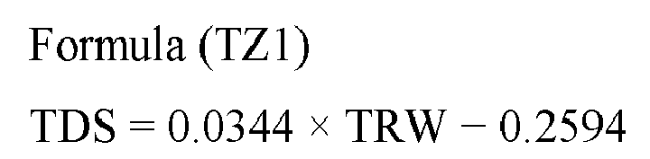
- In the
tire 2, the flow of the unvulcanized rubber is controlled on the basis of the contours of eachshoulder land surface 46s and the land surfaces 46 each located between twocircumferential grooves 42. However, in the case where disturbance of the inner surface occurs at the center portion of thetread 4, the flow of the unvulcanized rubber may be controlled on the basis of the contours of the land surfaces 46 each located between twocircumferential grooves 42, and, in the case where disturbance of the inner surface occurs at the shoulder portions of thetread 4, the flow of the unvulcanized rubber may be controlled on the basis of the contour of eachshoulder land surface 46s. From the viewpoint of making the ground-contact surface shape and the ground-contact pressure distribution of thetire 2 sufficiently appropriate, the flow of the unvulcanized rubber is preferably controlled on the basis of the contours of eachshoulder land surface 46s and the land surfaces 46 each located between twocircumferential grooves 42. - As described above, with the
tire mold 48 and the production method for a tire according to the present invention, the ground-contact surface shape and the ground-contact pressure distribution of thetire 2 can be made appropriate. In thetire 2 obtained by thetire mold 48 and the production method for a tire, an appropriate ground-contact surface shape and an appropriate ground-contact pressure distribution are obtained, and thus steering stability and wear resistance can be improved. - As described above, the
projections 66 on the tread-formingsurface 56 press thecap portion 26. The present invention exhibits a remarkable effect in the case where the unvulcanized rubber for thecap portion 26 has a Mooney viscosity of not less than 80. The Mooney viscosity means a Mooney viscosity ML1+4(100°C) and is measured according to JIS K6300-1. - The above-described technology to make the ground-contact surface shape and the ground-contact pressure distribution of the tire appropriate can also be applied to various tires.
Claims (9)
- A tire mold (48) used for producing a tire (2) including a tread (4) having a tread surface (22) that comes into contact with a road surface, at least two circumferential grooves (42, 42s, 42m, 42w, 42n) having a groove width of not less than 9 mm being formed on the tread (4) so as to extend in a circumferential direction, thereby forming at least three land portions (44, 44s, 44m) in the tread (4), the tread surface (22) including the at least two circumferential grooves (42, 42s, 42m, 42w, 42n) and at least three land surfaces (46, 46s, 46m) that are outer surfaces of the at least three land portions (44, 44s, 44m), the tire mold (48) comprising:a tread-forming surface (56) for shaping the tread surface (22), whereinthe tread-forming surface (56) includes at least two projections (66, 66s, 66m, 66w, 66n) for forming the at least two circumferential grooves (42, 42s, 42m, 42w, 42n), and at least three land surface-forming portions (68, 68s, 68m) for forming the at least three land surfaces (46, 46s, 46m),a contour of a land surface-forming portion (68, 68m) located between two projections (66, 66s, 66m, 66w, 66n) among the at least three land surface-forming portions (68, 68s, 68m) is represented by a single circular arc that is convex outward, andin a case where, of the two projections (66, 66s, 66m, 66w, 66n), one projection is a wide projection (66w) having a larger width than the other projection, and the other projection is a narrow projection (66n) having a smaller width than the one projection,when a surface that has a contour represented by at least one circular arc and that is tangent to the at least three land surface-forming portions (68, 68s, 68m) is defined as a reference surface (FBL) of the tread-forming surface (56),a wide-side drop distance MDW that is a distance from the reference surface (FBL) of the tread-forming surface (56) to an end (Pfw) on the wide projection (66w) side of the land surface-forming portion (68, 68m) is longer than a narrow-side drop distance MDN that is a distance from the reference surface (FBL) of the tread-forming surface (56) to an end (Pfn) on the narrow projection (66n) side of the land surface-forming portion (68, 68m).
- The tire mold (48) according to claim 1, wherein
in a case where a width of each projection (66) is not less than 9 mm and not greater than 12 mm, the narrow-side drop distance MDN is not less than 0.01 mm, and the wide-side drop distance MDW is not greater than 0.3 mm, and
in a case where the width of each projection (66) is greater than 12 mm, the narrow-side drop distance MDN satisfies the following formula (MN1) represented using a width MRN of the narrow projection (66n), and the wide-side drop distance MDW satisfies the following formula (MW1) represented using a width MRW of the wide projection (66w),

- A tire mold (48) used for producing a tire (2) including a tread (4) having a tread surface (22) that comes into contact with a road surface, at least two circumferential grooves (42, 42s, 42m, 42w, 42n) having a groove width of not less than 9 mm being formed on the tread (4) so as to extend in a circumferential direction, thereby forming at least three land portions (44, 44s, 44m) in the tread (4), the tread surface (22) including the at least two circumferential grooves (42, 42s, 42m, 42w, 42n) and at least three land surfaces (46, 46s, 46m) that are outer surfaces of the at least three land portions (44, 44s, 44m), the tire mold (48) comprising:a tread-forming surface (56) for shaping the tread surface (22), whereinthe tread-forming surface (56) includes at least two projections (66, 66s, 66m, 66w, 66n) for forming the at least two circumferential grooves (42, 42s, 42m, 42w, 42n), and at least three land surface-forming portions (68, 68s, 68m) for forming the at least three land surfaces (46, 46s, 46m),among the at least three land surface-forming portions (68, 68s, 68m), a land surface-forming portion located on each outer side in an axial direction is a shoulder land surface-forming portion (68s), a land surface-forming portion located inward of the shoulder land surface-forming portion (68s) is a middle land surface-forming portion (68m), and a projection between the shoulder land surface-forming portion (68s) and the middle land surface-forming portion (68m) is a shoulder projection (66s), andwhen a surface that has a contour represented by at least one circular arc and that is tangent to the at least three land surface-forming portions (68, 68s, 68m) is defined as a reference surface (FBL) of the tread-forming surface (56), and a tangent point between the shoulder land surface-forming portion (68s) and the reference surface (FBL) of the tread-forming surface (56) on the shoulder projection (66s) side is defined as a reference position (Pfb),a contour of a portion from an end (Pfs) on the shoulder projection (66s) side of the shoulder land surface-forming portion (68s) to the reference position (Pfb) is represented by a single circular arc.
- The tire mold (48) according to claim 3, wherein, when a width of the middle land surface-forming portion (68m) is denoted by MY, a distance MZ from the end (Pfs) on the shoulder projection (66s) side to the reference position (Pfb) satisfies the following formula (MS1),

- The tire mold (48) according to claim 3 or 4, wherein a shoulder-side drop distance MDS that is a distance from the reference surface (FBL) of the tread-forming surface (56) to the end (Pfs) on the shoulder projection (66s) side of the shoulder land surface-forming portion (68s) is not less than 0.05 mm and not greater than 0.6 mm.
- The tire mold (48) according to any one of claims 1 to 5, wherein
the tread (4) includes a cap portion (26) including the tread surface (22), and
an unvulcanized rubber for the cap portion (26) has a Mooney viscosity of not less than 80. - A production method for a tire (2), comprising a step of pressurizing and heating a green tire (2r) using the tire mold (48) according to any one of claims 1 to 6.
- A tire (2) comprising a tread (4) having a tread surface (22) that comes into contact with a road surface, wherein
at least two circumferential grooves (42, 42s, 42m, 42w, 42n) having a groove width of not less than 9 mm are formed on the tread (4) so as to extend in a circumferential direction, thereby forming at least three land portions (44, 44s, 44m) in the tread (4),
the tread surface (22) includes the at least two circumferential grooves (42, 42s, 42m, 42w, 42n) and at least three land surfaces (46, 46s, 46m) that are outer surfaces of the at least three land portions (44, 44s, 44m),
a contour of a land surface (46, 46m) located between two circumferential grooves (42, 42s, 42m, 42w, 42n) among the at least three land surfaces (46, 46s, 46m) is represented by a single circular arc that is convex outward, and
in a case where, of the two circumferential grooves (42, 42s, 42m, 42w, 42n), one circumferential groove is a wide circumferential groove (42w) having a larger groove width than the other circumferential groove, and the other circumferential groove is a narrow circumferential groove (42n) having a smaller groove width than the one circumferential groove,
when a surface that has a contour represented by at least one circular arc and that is tangent to the at least three land surfaces (46, 46s, 46m) is defined as a reference surface (TBL) of the tread surface (22),
a wide-side drop distance TDW that is a distance from the reference surface (TBL) of the tread surface (22) to an end (Ptw) on the wide circumferential groove (42w) side of the land surface (46, 46m) is longer than a narrow-side drop distance TDN that is a distance from the reference surface (TBL) of the tread surface (22) to an end (Ptn) on the narrow circumferential groove (42n) side of the land surface (46, 46m). - A tire (2) comprising a tread (4) having a tread surface (22) that comes into contact with a road surface, wherein
at least two circumferential grooves (42, 42s, 42m, 42w, 42n) having a groove width of not less than 9 mm are formed on the tread (4) so as to extend in a circumferential direction, thereby forming at least three land portions (44, 44s, 44m) in the tread (4),
the tread surface (22) includes the at least two circumferential grooves (42, 42s, 42m, 42w, 42n) and at least three land surfaces (46, 46s, 46m) that are outer surfaces of the at least three land portions (44, 44s, 44m),
among the at least three land surfaces (46, 46s, 46m), a land surface located on each outer side in an axial direction is a shoulder land surface (46s), a land surface located inward of the shoulder land surface (46s) is a middle land surface (46m), and a circumferential groove between the shoulder land surface (46s) and the middle land surface (46m) is a shoulder circumferential groove (42s), and
when a surface that has a contour represented by at least one circular arc and that is tangent to the at least three land surfaces (46, 46s, 46m) is defined as a reference surface (TBL) of the tread surface (22), and a tangent point between the shoulder land surface (46s) and the reference surface (TBL) of the tread surface (22) on the shoulder circumferential groove (42s) side is defined as a reference position (Ptb),
a contour of a portion from an end (Pts) on the shoulder circumferential groove (42s) side of the shoulder land surface (46s) to the reference position (Ptb) is represented by a single circular arc.
Applications Claiming Priority (1)
| Application Number | Priority Date | Filing Date | Title |
|---|---|---|---|
| JP2020009230A JP7505188B2 (en) | 2020-01-23 | 2020-01-23 | Tire mold, tire manufacturing method, and tire |
Publications (2)
| Publication Number | Publication Date |
|---|---|
| EP3854574A1 true EP3854574A1 (en) | 2021-07-28 |
| EP3854574B1 EP3854574B1 (en) | 2022-07-20 |
Family
ID=74186461
Family Applications (1)
| Application Number | Title | Priority Date | Filing Date |
|---|---|---|---|
| EP21151778.4A Active EP3854574B1 (en) | 2020-01-23 | 2021-01-15 | Tire mold, production method for tire, and tire |
Country Status (4)
| Country | Link |
|---|---|
| US (1) | US11884034B2 (en) |
| EP (1) | EP3854574B1 (en) |
| JP (1) | JP7505188B2 (en) |
| CN (1) | CN113146891B (en) |
Families Citing this family (2)
| Publication number | Priority date | Publication date | Assignee | Title |
|---|---|---|---|---|
| WO2021201249A1 (en) * | 2020-04-01 | 2021-10-07 | 横浜ゴム株式会社 | Tire |
| JP7669668B2 (en) * | 2020-11-19 | 2025-04-30 | 住友ゴム工業株式会社 | Tire mold, tire manufacturing method, and tire |
Citations (3)
| Publication number | Priority date | Publication date | Assignee | Title |
|---|---|---|---|---|
| JP2014061602A (en) | 2012-09-20 | 2014-04-10 | Sumitomo Rubber Ind Ltd | Manufacturing method for tread member, extrusion mold for tread member, and tire |
| JP2016055722A (en) * | 2014-09-08 | 2016-04-21 | 横浜ゴム株式会社 | Pneumatic tire |
| EP3315325A1 (en) * | 2016-10-26 | 2018-05-02 | Sumitomo Rubber Industries, Ltd. | Pneumatic tire |
Family Cites Families (11)
| Publication number | Priority date | Publication date | Assignee | Title |
|---|---|---|---|---|
| JP4565710B2 (en) | 2000-07-21 | 2010-10-20 | 株式会社ブリヂストン | Pneumatic tire |
| JP2008238963A (en) | 2007-03-27 | 2008-10-09 | Bridgestone Corp | Pneumatic tire |
| JP5123980B2 (en) * | 2010-04-19 | 2013-01-23 | 住友ゴム工業株式会社 | Pneumatic tire |
| US10307864B2 (en) | 2013-12-13 | 2019-06-04 | Avonisys Ag | Methods and systems to keep a work piece surface free from liquid accumulation while performing liquid-jet guided laser based material processing |
| JP6425531B2 (en) | 2013-12-13 | 2018-11-21 | 株式会社ブリヂストン | Pneumatic tire |
| JP6819212B2 (en) * | 2016-10-26 | 2021-01-27 | 住友ゴム工業株式会社 | Pneumatic tires |
| JP6900707B2 (en) | 2017-03-01 | 2021-07-07 | 横浜ゴム株式会社 | Tire vulcanization mold, tire manufacturing method and pneumatic tire |
| JP7007925B2 (en) * | 2018-01-22 | 2022-01-25 | Toyo Tire株式会社 | Pneumatic tires |
| JP2019131081A (en) | 2018-01-31 | 2019-08-08 | Toyo Tire株式会社 | Pneumatic tire |
| JP6791203B2 (en) | 2018-05-16 | 2020-11-25 | 横浜ゴム株式会社 | Rubber composition for tire tread and pneumatic tire |
| JP6610717B1 (en) * | 2018-07-02 | 2019-11-27 | 横浜ゴム株式会社 | Pneumatic tire |
-
2020
- 2020-01-23 JP JP2020009230A patent/JP7505188B2/en active Active
-
2021
- 2021-01-08 CN CN202110023684.7A patent/CN113146891B/en active Active
- 2021-01-15 EP EP21151778.4A patent/EP3854574B1/en active Active
- 2021-01-22 US US17/155,088 patent/US11884034B2/en active Active
Patent Citations (3)
| Publication number | Priority date | Publication date | Assignee | Title |
|---|---|---|---|---|
| JP2014061602A (en) | 2012-09-20 | 2014-04-10 | Sumitomo Rubber Ind Ltd | Manufacturing method for tread member, extrusion mold for tread member, and tire |
| JP2016055722A (en) * | 2014-09-08 | 2016-04-21 | 横浜ゴム株式会社 | Pneumatic tire |
| EP3315325A1 (en) * | 2016-10-26 | 2018-05-02 | Sumitomo Rubber Industries, Ltd. | Pneumatic tire |
Also Published As
| Publication number | Publication date |
|---|---|
| JP2021115735A (en) | 2021-08-10 |
| US11884034B2 (en) | 2024-01-30 |
| CN113146891B (en) | 2024-05-28 |
| US20210229383A1 (en) | 2021-07-29 |
| EP3854574B1 (en) | 2022-07-20 |
| JP7505188B2 (en) | 2024-06-25 |
| CN113146891A (en) | 2021-07-23 |
Similar Documents
| Publication | Publication Date | Title |
|---|---|---|
| JP2021120242A (en) | Tire and method of manufacturing tire | |
| EP3854574B1 (en) | Tire mold, production method for tire, and tire | |
| US10052916B2 (en) | Pneumatic tire | |
| US20140332131A1 (en) | Pneumatic tire | |
| EP3800069B1 (en) | Heavy-duty pneumatic tire and manufacturing method thereof | |
| US9902200B2 (en) | Pneumatic tire | |
| US11390120B2 (en) | Heavy duty pneumatic tire | |
| JP2017013564A (en) | Pneumatic tire, and method for manufacturing the same | |
| US11865800B2 (en) | Tire mold and production method for tire using a tire mold | |
| US12187083B2 (en) | Heavy duty tire and production method for heavy duty tire | |
| KR20110126527A (en) | Pneumatic tires and manufacturing method thereof | |
| JP2020116976A (en) | Heavy load pneumatic tire | |
| EP3798023A1 (en) | Pneumatic tire | |
| US20230058858A1 (en) | Heavy duty pneumatic tire | |
| JP6177282B2 (en) | Pneumatic tire | |
| JP2024031211A (en) | tire | |
| JP7135508B2 (en) | Method for manufacturing pneumatic tires | |
| GB1565300A (en) | Foldable pneumatic tyre | |
| JP2024031216A (en) | tire | |
| JP2023080490A (en) | Method for manufacturing pneumatic tires | |
| JP2025059747A (en) | tire | |
| JP6536204B2 (en) | Method of manufacturing pneumatic tire | |
| JP2020116787A (en) | Die plate, tread rubber member manufacturing method, and tire manufacturing method |
Legal Events
| Date | Code | Title | Description |
|---|---|---|---|
| PUAI | Public reference made under article 153(3) epc to a published international application that has entered the european phase |
Free format text: ORIGINAL CODE: 0009012 |
|
| STAA | Information on the status of an ep patent application or granted ep patent |
Free format text: STATUS: THE APPLICATION HAS BEEN PUBLISHED |
|
| AK | Designated contracting states |
Kind code of ref document: A1 Designated state(s): AL AT BE BG CH CY CZ DE DK EE ES FI FR GB GR HR HU IE IS IT LI LT LU LV MC MK MT NL NO PL PT RO RS SE SI SK SM TR |
|
| STAA | Information on the status of an ep patent application or granted ep patent |
Free format text: STATUS: REQUEST FOR EXAMINATION WAS MADE |
|
| 17P | Request for examination filed |
Effective date: 20211028 |
|
| RBV | Designated contracting states (corrected) |
Designated state(s): AL AT BE BG CH CY CZ DE DK EE ES FI FR GB GR HR HU IE IS IT LI LT LU LV MC MK MT NL NO PL PT RO RS SE SI SK SM TR |
|
| GRAP | Despatch of communication of intention to grant a patent |
Free format text: ORIGINAL CODE: EPIDOSNIGR1 |
|
| STAA | Information on the status of an ep patent application or granted ep patent |
Free format text: STATUS: GRANT OF PATENT IS INTENDED |
|
| RIC1 | Information provided on ipc code assigned before grant |
Ipc: B29D 30/06 20060101AFI20220315BHEP |
|
| INTG | Intention to grant announced |
Effective date: 20220328 |
|
| GRAS | Grant fee paid |
Free format text: ORIGINAL CODE: EPIDOSNIGR3 |
|
| GRAA | (expected) grant |
Free format text: ORIGINAL CODE: 0009210 |
|
| STAA | Information on the status of an ep patent application or granted ep patent |
Free format text: STATUS: THE PATENT HAS BEEN GRANTED |
|
| AK | Designated contracting states |
Kind code of ref document: B1 Designated state(s): AL AT BE BG CH CY CZ DE DK EE ES FI FR GB GR HR HU IE IS IT LI LT LU LV MC MK MT NL NO PL PT RO RS SE SI SK SM TR |
|
| REG | Reference to a national code |
Ref country code: CH Ref legal event code: EP |
|
| REG | Reference to a national code |
Ref country code: DE Ref legal event code: R096 Ref document number: 602021000214 Country of ref document: DE |
|
| REG | Reference to a national code |
Ref country code: AT Ref legal event code: REF Ref document number: 1505272 Country of ref document: AT Kind code of ref document: T Effective date: 20220815 |
|
| REG | Reference to a national code |
Ref country code: IE Ref legal event code: FG4D |
|
| REG | Reference to a national code |
Ref country code: LT Ref legal event code: MG9D |
|
| REG | Reference to a national code |
Ref country code: NL Ref legal event code: MP Effective date: 20220720 |
|
| PG25 | Lapsed in a contracting state [announced via postgrant information from national office to epo] |
Ref country code: SE Free format text: LAPSE BECAUSE OF FAILURE TO SUBMIT A TRANSLATION OF THE DESCRIPTION OR TO PAY THE FEE WITHIN THE PRESCRIBED TIME-LIMIT Effective date: 20220720 Ref country code: RS Free format text: LAPSE BECAUSE OF FAILURE TO SUBMIT A TRANSLATION OF THE DESCRIPTION OR TO PAY THE FEE WITHIN THE PRESCRIBED TIME-LIMIT Effective date: 20220720 Ref country code: PT Free format text: LAPSE BECAUSE OF FAILURE TO SUBMIT A TRANSLATION OF THE DESCRIPTION OR TO PAY THE FEE WITHIN THE PRESCRIBED TIME-LIMIT Effective date: 20221121 Ref country code: NO Free format text: LAPSE BECAUSE OF FAILURE TO SUBMIT A TRANSLATION OF THE DESCRIPTION OR TO PAY THE FEE WITHIN THE PRESCRIBED TIME-LIMIT Effective date: 20221020 Ref country code: NL Free format text: LAPSE BECAUSE OF FAILURE TO SUBMIT A TRANSLATION OF THE DESCRIPTION OR TO PAY THE FEE WITHIN THE PRESCRIBED TIME-LIMIT Effective date: 20220720 Ref country code: LV Free format text: LAPSE BECAUSE OF FAILURE TO SUBMIT A TRANSLATION OF THE DESCRIPTION OR TO PAY THE FEE WITHIN THE PRESCRIBED TIME-LIMIT Effective date: 20220720 Ref country code: LT Free format text: LAPSE BECAUSE OF FAILURE TO SUBMIT A TRANSLATION OF THE DESCRIPTION OR TO PAY THE FEE WITHIN THE PRESCRIBED TIME-LIMIT Effective date: 20220720 Ref country code: FI Free format text: LAPSE BECAUSE OF FAILURE TO SUBMIT A TRANSLATION OF THE DESCRIPTION OR TO PAY THE FEE WITHIN THE PRESCRIBED TIME-LIMIT Effective date: 20220720 Ref country code: ES Free format text: LAPSE BECAUSE OF FAILURE TO SUBMIT A TRANSLATION OF THE DESCRIPTION OR TO PAY THE FEE WITHIN THE PRESCRIBED TIME-LIMIT Effective date: 20220720 |
|
| REG | Reference to a national code |
Ref country code: AT Ref legal event code: MK05 Ref document number: 1505272 Country of ref document: AT Kind code of ref document: T Effective date: 20220720 |
|
| PG25 | Lapsed in a contracting state [announced via postgrant information from national office to epo] |
Ref country code: PL Free format text: LAPSE BECAUSE OF FAILURE TO SUBMIT A TRANSLATION OF THE DESCRIPTION OR TO PAY THE FEE WITHIN THE PRESCRIBED TIME-LIMIT Effective date: 20220720 Ref country code: IS Free format text: LAPSE BECAUSE OF FAILURE TO SUBMIT A TRANSLATION OF THE DESCRIPTION OR TO PAY THE FEE WITHIN THE PRESCRIBED TIME-LIMIT Effective date: 20221120 Ref country code: HR Free format text: LAPSE BECAUSE OF FAILURE TO SUBMIT A TRANSLATION OF THE DESCRIPTION OR TO PAY THE FEE WITHIN THE PRESCRIBED TIME-LIMIT Effective date: 20220720 Ref country code: GR Free format text: LAPSE BECAUSE OF FAILURE TO SUBMIT A TRANSLATION OF THE DESCRIPTION OR TO PAY THE FEE WITHIN THE PRESCRIBED TIME-LIMIT Effective date: 20221021 |
|
| REG | Reference to a national code |
Ref country code: DE Ref legal event code: R097 Ref document number: 602021000214 Country of ref document: DE |
|
| PG25 | Lapsed in a contracting state [announced via postgrant information from national office to epo] |
Ref country code: SM Free format text: LAPSE BECAUSE OF FAILURE TO SUBMIT A TRANSLATION OF THE DESCRIPTION OR TO PAY THE FEE WITHIN THE PRESCRIBED TIME-LIMIT Effective date: 20220720 Ref country code: RO Free format text: LAPSE BECAUSE OF FAILURE TO SUBMIT A TRANSLATION OF THE DESCRIPTION OR TO PAY THE FEE WITHIN THE PRESCRIBED TIME-LIMIT Effective date: 20220720 Ref country code: DK Free format text: LAPSE BECAUSE OF FAILURE TO SUBMIT A TRANSLATION OF THE DESCRIPTION OR TO PAY THE FEE WITHIN THE PRESCRIBED TIME-LIMIT Effective date: 20220720 Ref country code: CZ Free format text: LAPSE BECAUSE OF FAILURE TO SUBMIT A TRANSLATION OF THE DESCRIPTION OR TO PAY THE FEE WITHIN THE PRESCRIBED TIME-LIMIT Effective date: 20220720 Ref country code: AT Free format text: LAPSE BECAUSE OF FAILURE TO SUBMIT A TRANSLATION OF THE DESCRIPTION OR TO PAY THE FEE WITHIN THE PRESCRIBED TIME-LIMIT Effective date: 20220720 |
|
| PLBE | No opposition filed within time limit |
Free format text: ORIGINAL CODE: 0009261 |
|
| STAA | Information on the status of an ep patent application or granted ep patent |
Free format text: STATUS: NO OPPOSITION FILED WITHIN TIME LIMIT |
|
| PG25 | Lapsed in a contracting state [announced via postgrant information from national office to epo] |
Ref country code: SK Free format text: LAPSE BECAUSE OF FAILURE TO SUBMIT A TRANSLATION OF THE DESCRIPTION OR TO PAY THE FEE WITHIN THE PRESCRIBED TIME-LIMIT Effective date: 20220720 Ref country code: EE Free format text: LAPSE BECAUSE OF FAILURE TO SUBMIT A TRANSLATION OF THE DESCRIPTION OR TO PAY THE FEE WITHIN THE PRESCRIBED TIME-LIMIT Effective date: 20220720 |
|
| P01 | Opt-out of the competence of the unified patent court (upc) registered |
Effective date: 20230510 |
|
| 26N | No opposition filed |
Effective date: 20230421 |
|
| PG25 | Lapsed in a contracting state [announced via postgrant information from national office to epo] |
Ref country code: AL Free format text: LAPSE BECAUSE OF FAILURE TO SUBMIT A TRANSLATION OF THE DESCRIPTION OR TO PAY THE FEE WITHIN THE PRESCRIBED TIME-LIMIT Effective date: 20220720 |
|
| PG25 | Lapsed in a contracting state [announced via postgrant information from national office to epo] |
Ref country code: SI Free format text: LAPSE BECAUSE OF FAILURE TO SUBMIT A TRANSLATION OF THE DESCRIPTION OR TO PAY THE FEE WITHIN THE PRESCRIBED TIME-LIMIT Effective date: 20220720 |
|
| PG25 | Lapsed in a contracting state [announced via postgrant information from national office to epo] |
Ref country code: LU Free format text: LAPSE BECAUSE OF NON-PAYMENT OF DUE FEES Effective date: 20230115 |
|
| REG | Reference to a national code |
Ref country code: BE Ref legal event code: MM Effective date: 20230131 |
|
| PG25 | Lapsed in a contracting state [announced via postgrant information from national office to epo] |
Ref country code: BE Free format text: LAPSE BECAUSE OF NON-PAYMENT OF DUE FEES Effective date: 20230131 |
|
| PG25 | Lapsed in a contracting state [announced via postgrant information from national office to epo] |
Ref country code: IE Free format text: LAPSE BECAUSE OF NON-PAYMENT OF DUE FEES Effective date: 20230115 |
|
| PG25 | Lapsed in a contracting state [announced via postgrant information from national office to epo] |
Ref country code: IT Free format text: LAPSE BECAUSE OF FAILURE TO SUBMIT A TRANSLATION OF THE DESCRIPTION OR TO PAY THE FEE WITHIN THE PRESCRIBED TIME-LIMIT Effective date: 20220720 |
|
| PG25 | Lapsed in a contracting state [announced via postgrant information from national office to epo] |
Ref country code: MC Free format text: LAPSE BECAUSE OF FAILURE TO SUBMIT A TRANSLATION OF THE DESCRIPTION OR TO PAY THE FEE WITHIN THE PRESCRIBED TIME-LIMIT Effective date: 20220720 |
|
| PG25 | Lapsed in a contracting state [announced via postgrant information from national office to epo] |
Ref country code: MC Free format text: LAPSE BECAUSE OF FAILURE TO SUBMIT A TRANSLATION OF THE DESCRIPTION OR TO PAY THE FEE WITHIN THE PRESCRIBED TIME-LIMIT Effective date: 20220720 |
|
| REG | Reference to a national code |
Ref country code: CH Ref legal event code: PL |
|
| PG25 | Lapsed in a contracting state [announced via postgrant information from national office to epo] |
Ref country code: CH Free format text: LAPSE BECAUSE OF NON-PAYMENT OF DUE FEES Effective date: 20240131 |
|
| PG25 | Lapsed in a contracting state [announced via postgrant information from national office to epo] |
Ref country code: CH Free format text: LAPSE BECAUSE OF NON-PAYMENT OF DUE FEES Effective date: 20240131 |
|
| PG25 | Lapsed in a contracting state [announced via postgrant information from national office to epo] |
Ref country code: BG Free format text: LAPSE BECAUSE OF FAILURE TO SUBMIT A TRANSLATION OF THE DESCRIPTION OR TO PAY THE FEE WITHIN THE PRESCRIBED TIME-LIMIT Effective date: 20220720 |
|
| PG25 | Lapsed in a contracting state [announced via postgrant information from national office to epo] |
Ref country code: BG Free format text: LAPSE BECAUSE OF FAILURE TO SUBMIT A TRANSLATION OF THE DESCRIPTION OR TO PAY THE FEE WITHIN THE PRESCRIBED TIME-LIMIT Effective date: 20220720 |
|
| PG25 | Lapsed in a contracting state [announced via postgrant information from national office to epo] |
Ref country code: CY Free format text: LAPSE BECAUSE OF FAILURE TO SUBMIT A TRANSLATION OF THE DESCRIPTION OR TO PAY THE FEE WITHIN THE PRESCRIBED TIME-LIMIT; INVALID AB INITIO Effective date: 20210115 |
|
| PG25 | Lapsed in a contracting state [announced via postgrant information from national office to epo] |
Ref country code: HU Free format text: LAPSE BECAUSE OF FAILURE TO SUBMIT A TRANSLATION OF THE DESCRIPTION OR TO PAY THE FEE WITHIN THE PRESCRIBED TIME-LIMIT; INVALID AB INITIO Effective date: 20210115 |
|
| GBPC | Gb: european patent ceased through non-payment of renewal fee |
Effective date: 20250115 |
|
| PG25 | Lapsed in a contracting state [announced via postgrant information from national office to epo] |
Ref country code: GB Free format text: LAPSE BECAUSE OF NON-PAYMENT OF DUE FEES Effective date: 20250115 |
|
| PG25 | Lapsed in a contracting state [announced via postgrant information from national office to epo] |
Ref country code: TR Free format text: LAPSE BECAUSE OF FAILURE TO SUBMIT A TRANSLATION OF THE DESCRIPTION OR TO PAY THE FEE WITHIN THE PRESCRIBED TIME-LIMIT Effective date: 20220720 |
|
| PGFP | Annual fee paid to national office [announced via postgrant information from national office to epo] |
Ref country code: FR Payment date: 20251128 Year of fee payment: 6 |
|
| PGFP | Annual fee paid to national office [announced via postgrant information from national office to epo] |
Ref country code: DE Payment date: 20251203 Year of fee payment: 6 |