EP3853809B1 - Anzeigezuordnung für bilder mit hohem dynamikbereich auf leistungsbegrenzenden anzeigevorrichtungen - Google Patents
Anzeigezuordnung für bilder mit hohem dynamikbereich auf leistungsbegrenzenden anzeigevorrichtungen Download PDFInfo
- Publication number
- EP3853809B1 EP3853809B1 EP19774039.2A EP19774039A EP3853809B1 EP 3853809 B1 EP3853809 B1 EP 3853809B1 EP 19774039 A EP19774039 A EP 19774039A EP 3853809 B1 EP3853809 B1 EP 3853809B1
- Authority
- EP
- European Patent Office
- Prior art keywords
- target display
- luminance
- tmax
- anchor point
- mapping
- Prior art date
- Legal status (The legal status is an assumption and is not a legal conclusion. Google has not performed a legal analysis and makes no representation as to the accuracy of the status listed.)
- Active
Links
Images




Classifications
-
- G—PHYSICS
- G06—COMPUTING OR CALCULATING; COUNTING
- G06T—IMAGE DATA PROCESSING OR GENERATION, IN GENERAL
- G06T5/00—Image enhancement or restoration
- G06T5/90—Dynamic range modification of images or parts thereof
- G06T5/92—Dynamic range modification of images or parts thereof based on global image properties
-
- G—PHYSICS
- G09—EDUCATION; CRYPTOGRAPHY; DISPLAY; ADVERTISING; SEALS
- G09G—ARRANGEMENTS OR CIRCUITS FOR CONTROL OF INDICATING DEVICES USING STATIC MEANS TO PRESENT VARIABLE INFORMATION
- G09G5/00—Control arrangements or circuits for visual indicators common to cathode-ray tube indicators and other visual indicators
- G09G5/003—Details of a display terminal, the details relating to the control arrangement of the display terminal and to the interfaces thereto
- G09G5/005—Adapting incoming signals to the display format of the display terminal
-
- G—PHYSICS
- G09—EDUCATION; CRYPTOGRAPHY; DISPLAY; ADVERTISING; SEALS
- G09G—ARRANGEMENTS OR CIRCUITS FOR CONTROL OF INDICATING DEVICES USING STATIC MEANS TO PRESENT VARIABLE INFORMATION
- G09G5/00—Control arrangements or circuits for visual indicators common to cathode-ray tube indicators and other visual indicators
- G09G5/10—Intensity circuits
-
- G—PHYSICS
- G06—COMPUTING OR CALCULATING; COUNTING
- G06T—IMAGE DATA PROCESSING OR GENERATION, IN GENERAL
- G06T2207/00—Indexing scheme for image analysis or image enhancement
- G06T2207/20—Special algorithmic details
- G06T2207/20172—Image enhancement details
- G06T2207/20208—High dynamic range [HDR] image processing
-
- G—PHYSICS
- G09—EDUCATION; CRYPTOGRAPHY; DISPLAY; ADVERTISING; SEALS
- G09G—ARRANGEMENTS OR CIRCUITS FOR CONTROL OF INDICATING DEVICES USING STATIC MEANS TO PRESENT VARIABLE INFORMATION
- G09G2320/00—Control of display operating conditions
- G09G2320/06—Adjustment of display parameters
- G09G2320/0626—Adjustment of display parameters for control of overall brightness
-
- G—PHYSICS
- G09—EDUCATION; CRYPTOGRAPHY; DISPLAY; ADVERTISING; SEALS
- G09G—ARRANGEMENTS OR CIRCUITS FOR CONTROL OF INDICATING DEVICES USING STATIC MEANS TO PRESENT VARIABLE INFORMATION
- G09G2320/00—Control of display operating conditions
- G09G2320/06—Adjustment of display parameters
- G09G2320/0666—Adjustment of display parameters for control of colour parameters, e.g. colour temperature
-
- G—PHYSICS
- G09—EDUCATION; CRYPTOGRAPHY; DISPLAY; ADVERTISING; SEALS
- G09G—ARRANGEMENTS OR CIRCUITS FOR CONTROL OF INDICATING DEVICES USING STATIC MEANS TO PRESENT VARIABLE INFORMATION
- G09G2320/00—Control of display operating conditions
- G09G2320/06—Adjustment of display parameters
- G09G2320/0673—Adjustment of display parameters for control of gamma adjustment, e.g. selecting another gamma curve
-
- G—PHYSICS
- G09—EDUCATION; CRYPTOGRAPHY; DISPLAY; ADVERTISING; SEALS
- G09G—ARRANGEMENTS OR CIRCUITS FOR CONTROL OF INDICATING DEVICES USING STATIC MEANS TO PRESENT VARIABLE INFORMATION
- G09G2330/00—Aspects of power supply; Aspects of display protection and defect management
- G09G2330/02—Details of power systems and of start or stop of display operation
- G09G2330/021—Power management, e.g. power saving
-
- G—PHYSICS
- G09—EDUCATION; CRYPTOGRAPHY; DISPLAY; ADVERTISING; SEALS
- G09G—ARRANGEMENTS OR CIRCUITS FOR CONTROL OF INDICATING DEVICES USING STATIC MEANS TO PRESENT VARIABLE INFORMATION
- G09G2360/00—Aspects of the architecture of display systems
- G09G2360/16—Calculation or use of calculated indices related to luminance levels in display data
-
- G—PHYSICS
- G09—EDUCATION; CRYPTOGRAPHY; DISPLAY; ADVERTISING; SEALS
- G09G—ARRANGEMENTS OR CIRCUITS FOR CONTROL OF INDICATING DEVICES USING STATIC MEANS TO PRESENT VARIABLE INFORMATION
- G09G3/00—Control arrangements or circuits, of interest only in connection with visual indicators other than cathode-ray tubes
- G09G3/20—Control arrangements or circuits, of interest only in connection with visual indicators other than cathode-ray tubes for presentation of an assembly of a number of characters, e.g. a page, by composing the assembly by combination of individual elements arranged in a matrix no fixed position being assigned to or needed to be assigned to the individual characters or partial characters
- G09G3/2007—Display of intermediate tones
Definitions
- the present invention relates generally to images. More particularly, an embodiment of the present invention relates to display mapping of high-dynamic range (HDR) images and video signals from a first dynamic range to a second dynamic range on power-limiting displays.
- HDR high-dynamic range
- HDR high dynamic range
- n ⁇ 8 e.g., color 24-bit JPEG images
- HDR images may also be stored and distributed using high-precision (e.g., 16-bit) floating-point formats, such as the OpenEXR file format developed by Industrial Light and Magic.
- Metadata relates to any auxiliary information that is transmitted as part of the coded bitstream and assists a decoder to render a decoded image.
- metadata may include, but are not limited to, color space or gamut information, reference display parameters, and auxiliary signal parameters, as those described herein.
- HDR lower dynamic range
- SDR standard dynamic range
- HDR content may be color graded and displayed on HDR displays that support higher dynamic ranges (e.g., from 1,000 nits to 5,000 nits or more).
- the methods of the present disclosure relate to any dynamic range.
- OETF non-linear opto-electronic function
- EOTF electro-optical transfer function
- mapping function (220) is defined by three anchor points (205, 210, 215): a black point (x1, y1), a mid-tones point (x2, y2), and a white point (x3, y3).
- This transformation has the following properties:
- FIG. 3 is a graphical depiction of another example tone-mapping curve 300 for mapping images from a first dynamic range [x 1 ,x 3 ] to a second dynamic range [y 1 ,y 3 ], where [x 1 ,x 3 ] are input channel values and [y 1 ,y 3 ] are output channel values.
- Tone-mapping curve 300 includes a spline 312, from (x 1 ,y 1 ) to (x 2 , y 2 ), and a spline 323, from (x 2 , y 2 ) to (x 3 ,y 3 ).
- Tone-mapping curve 300 intersects three anchor points 301, 302, and 303, the locations of which partly determine the shape of tone-mapping curve 300.
- Anchor points 301, 302, and 303 are located at respective coordinates ( x 1 , y 1 ), ( x 2 , y 2 ), and ( x 3 , y 3 ), which respectively correspond to black points (e.g., xmin, Tmin ) , mid-tone value points (e.g., xmid, Tmid ), and white points (e.g., xmax, Tmax ) when channel values x i are input luminance values and Tmin, Tmid, and Tmax may denote the minimum, mid (or average), and maximum luminance values in a target display (e.g., 140).
- each of the spline segments can be further constrained by two slopes, at each end-point; thus tone-mapping curve 300 is controlled by three anchor points (301, 302, and 303) and three slopes: the tail slope at ( x 1 , y 1 ), the mid-tones slope at ( x 2 ,y 2 ), and the head slope at ( x 3 ,y 3 ) .
- Each display model has its own power limiting characteristics.
- To characterize the power limiting characteristics of a display one may measure the luminance of the display per APL input. This is found using a set of test patterns where the entire image is set to one code value. For example, a display that is completely red, green, or blue is considered 33% APL. These test patterns can be in a range from 0-100%.
- An example measurement of display luminance (in nits) as a function of APL percentage input is given in FIG. 4 .
- Such a plot provides a physical characteristic of the panel and can be used to define a more accurate value of Tmax.
- the plot data may be saved in a display configuration file (along with other typical panel properties).
- the Y axis e.g., luminance
- the Y axis may be represented in gamma luminance or PQ luminance values instead of linear luminance.
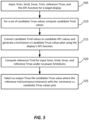
- FIG. 5 depicts an example process for generating adaptive output Tmax values according to an embodiment.
- the process starts by accessing the input metadata Smin, Smid, and Smax, and the target display characteristics.
- the target display characteristics may include the display's luminance as a function of input APL (e.g., an APL function as depicted in FIG.4 ) and Tmin and reference Tmax values (denoted as Tmin_ref and Tmax_ref ) assuming no power limitations.
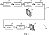
- the goal of this process is to identify the best value for setting Tmax to derive a display management mapping function (e.g., 220 or 300) to maintain the director's intent when mapping the input data (e.g., 132) to the target display (140).
- a display management mapping function e.g., 220 or 300
- step 510 the process selects a set of candidate Tmax values (to be denoted as Tmax_c(i)).
- Tmax_c(i) a set of candidate Tmax values
- step 510 computes candidate Tmid values (denoted as Tmid_c(i)).
- the process selects y2 values of the mid anchor points as depicted in FIG. 2 and FIG. 3 .
- Examples of generating a Tmid value given the characteristics of the input and a target display can be found in PCT Application Ser. No. PCT/US2018/012780, filed on Jan. 8, 2018 , "Display Mapping for High Dynamic Range Images,".
- TmaxPQ, TminPQ, and TmaxPQ_c(i) denote PQ-coded luminance values corresponding to the linear luminance values Tmax, Tmin, and Tmax_c(i), which have been converted to PQ luminance using SMPTE ST 2084.
- DM_CalcCuttoff() is defined as:
- the candidate Tmid_c(i) values are converted to candidate APL values (denoted as APL _c(i)).
- equation (5) assumes that to compute the APL response of the target display the input patches were converted by the display to BT. 1886 (gamma). In embodiments where that's not the case, this step can be replaced by the proper EOTF function being used to compute the APL response of the target display.
- Step 520 repeats steps 510 and 515, but now just for the Tmax_ref value and under no power limitations. That is, instead of using f A ( ), Luma (e.g., PQ-coded luminance) values are converted directly to linear luminance using the display's EOTF (e.g., by using the PQ2L() function for PQ-coded images).
- Luma e.g., PQ-coded luminance
- Y f Tmax _ ref ( x ) designed based on Tmin_ref, Tmax_ref, Smin, Smid, Smax, and P_o
- Embodiments of the present invention may be implemented with a computer system, systems configured in electronic circuitry and components, an integrated circuit (IC) device such as a microcontroller, a field programmable gate array (FPGA), or another configurable or programmable logic device (PLD), a discrete time or digital signal processor (DSP), an application specific IC (ASIC), and/or apparatus that includes one or more of such systems, devices or components.
- IC integrated circuit
- FPGA field programmable gate array
- PLD configurable or programmable logic device
- DSP discrete time or digital signal processor
- ASIC application specific IC
- the computer and/or IC may perform, control or execute instructions relating to mapping methods, such as those described herein.
- the computer and/or IC may compute, any of a variety of parameters or values that relate to reducing banding artifacts as described herein.
- the image and video dynamic range extension embodiments may be implemented in hardware, software, firmware and various combinations thereof.
- Certain implementations of the invention comprise computer processors which execute software instructions which cause the processors to perform a method of the invention.
- processors in a display, an encoder, a set top box, a transcoder or the like may implement mapping methods as described above by executing software instructions in a program memory accessible to the processors.
- the invention may also be provided in the form of a program product.
- the program product may comprise any non-transitory and tangible medium which carries a set of computer-readable signals comprising instructions which, when executed by a data processor, cause the data processor to execute a method of the invention.
- Program products according to the invention may be in any of a wide variety of non-transitory and tangible forms.
- the program product may comprise, for example, physical media such as magnetic data storage media including floppy diskettes, hard disk drives, optical data storage media including CD ROMs, DVDs, electronic data storage media including ROMs, flash RAM, or the like.
- the computer-readable signals on the program product may optionally be compressed or encrypted.
- a component e.g. a software module, processor, assembly, device, circuit, etc.
- reference to that component should be interpreted as including as equivalents of that component any component which performs the function of the described component (e.g., that is functionally equivalent), including components which are not structurally equivalent to the disclosed structure which performs the function in the illustrated example embodiments of the invention.
Landscapes
- Engineering & Computer Science (AREA)
- Physics & Mathematics (AREA)
- General Physics & Mathematics (AREA)
- Theoretical Computer Science (AREA)
- Computer Hardware Design (AREA)
- Image Processing (AREA)
- Controls And Circuits For Display Device (AREA)
- Compression Or Coding Systems Of Tv Signals (AREA)
- Picture Signal Circuits (AREA)
- Transforming Electric Information Into Light Information (AREA)
Claims (6)
- Verfahren zum Erzeugen eines einer Anzeige zugeordneten Bildes unter Verwendung von Tonzuordnungskurven mit einem ersten Ankerpunkt und einem zweiten Ankerpunkt, wobei das Verfahren umfasst:Empfangen (505) von Eingangsmetadaten für ein Eingangsbild, das auf einer Zielanzeige unter Verwendung der Tonzuordnungskurve von einem ersten Dynamikbereich zu einem zweiten Dynamikbereich zugeordnet werden soll, wobei die Eingangsmetadaten einen minimalen Luminanzpixelwert des Eingangsbildes Smin, einen mittleren oder durchschnittlichen Luminanzpixelwert des Eingangsbildes Smid und einen maximalen Luminanzpixelwert des Eingangsbildes Smax umfassen;Empfangen (505) einer Funktion für den durchschnittlichen Bildpegel (APL) der Zielanzeige, wobei die APL-Funktion die Ausgangsluminanz in der Zielanzeige als Funktion des APL-Eingangs in der Zielanzeige bestimmt;Empfangen (505) eines minimalen Luminanzpegels für die Zielanzeige Tmin und einer Referenz für den maximalen Luminanzpegel für die Zielanzeige Tmax_ref;Bestimmen einer ersten Tonzuordnungskurve mit Smin, Tmin als ersten Ankerpunkt und Smax, Tmax_ref als zweiten Ankerpunkt;Bestimmen (520) einer Referenz für den mittleren Luminanzpegel für die Zielanzeige Tmid_ref durch Zuordnen von Smid vom ersten Dynamikbereich zum zweiten Dynamikbereich unter Verwendung der ersten Tonzuordnungskurve mit Smin, Tmin als ersten Ankerpunkt und Smax, Tmax_ref als zweiten Ankerpunkt;Bestimmen einer zweiten Tonzuordnungskurve mit Smin, Tmin als ersten Ankerpunkt und Smax, Tmax_c als zweiten Ankerpunkt, wobei Tmax_c ein Kandidat für einen maximalen Luminanzwert ist;Bestimmen eines mittleren Luminanzpegels der Zielanzeige Tmid durch Zuordnen von Smid vom ersten Dynamikbereich zum zweiten Dynamikbereich unter Verwendung der zweiten Tonzuordnungskurve mit Smin, Tmin als ersten Ankerpunkt und Smax, Tmax_c als zweiten Ankerpunkt;Bestimmen (515) einer Funktion für die Luminanz versus Kandidat für den maximalen Luminanzpegel Tmax_c der Zielanzeige als Ausgang der APL-Funktion für einen APL-Eingang, der dem mittleren Luminanzpegel der Zielanzeige Tmid entspricht;Bestimmen (525) eines maximalen Ausgangsluminanzpegels der Zielanzeige Tmax auf Basis eines Tmax_c-Werts, bei dem der Ausgang der Funktion für die Luminanz versus Tmax_c näher an der Referenz für den mittleren Luminanzpegel der Zielanzeige Tmid_ref liegt,Bestimmen einer dritten Tonzuordnungskurve mit Smin, Tmin als ersten Ankerpunkt und Smax, Tmax als zweiten Ankerpunkt;Zuordnen des Eingangsbildes vom ersten Dynamikbereich zum zweiten Dynamikbereich unter Verwendung der dritten Tonzuordnungskurve mit Smin, Tmin als ersten Ankerpunkt und Smax, Tmax als zweiten Ankerpunkt;wobei das Bestimmen der Funktion für die Luminanz versus Tmax_c für die Zielanzeige umfasst:Bestimmen einer Menge von zwei oder mehr Kandidaten für maximale Luminanzwerte;für jeden Kandidaten für den maximalen Luminanzwert Tmax_c(i) in der Menge von Kandidaten für maximale Luminanzwerte:Erzeugen eines Kandidaten für den mittleren Luminanzwert für die Zielanzeige auf Basis des mittleren oder durchschnittlichen Luminanzpixelwerts des Eingangsbildes, des minimalen Luminanzpegels für die Zielanzeige und des Kandidaten für den maximalen Luminanzwert; undErzeugen einer Luminanz für den Tmax_c(i)-Wert auf Basis des Kandidaten für den mittleren Luminanzwert und der APL-Funktion der Zielanzeige.
- Verfahren nach Anspruch 1, wobei das Bestimmen der Referenz für den mittleren Luminanzpegel für die Zielanzeige umfasst:Erzeugen eines mittleren Referenz-PQ-Luminanzwerts für die Zielanzeige auf Basis des mittleren oder durchschnittlichen Luminanzpixelwerts des Eingangsbildes, des minimalen Luminanzpegels für die Zielanzeige und der Referenz für den maximalen Luminanzpegel für die Zielanzeige; undUmwandeln der mittleren Referenz-PQ-Luminanz in einen linearen mittleren Luminanzpegel unter Verwendung einer PQ-zu-lineare-Luminanz-Zuordnungsfunktion.
- Verfahren zum Erzeugen eines einer Anzeige zugeordneten Bildes unter Verwendung von Tonzuordnungskurven mit einem ersten Ankerpunkt und einem zweiten Ankerpunkt, wobei das Verfahren umfasst:Empfangen (705) von Eingangsmetadaten für ein Eingangsbild, das auf einer Zielanzeige unter Verwendung der Tonzuordnungskurve von einem ersten Dynamikbereich zu einem zweiten Dynamikbereich zugeordnet werden soll, wobei die Eingangsmetadaten einen minimalen Luminanzpixelwert des Eingangsbildes Smin, einen mittleren oder durchschnittlichen Luminanzpixelwert des Eingangsbildes Smid und einen maximalen Luminanzpixelwert des Eingangsbildes Smax umfassen;Empfangen (705) einer Funktion für den durchschnittlichen Bildpegel (APL) der Zielanzeige, wobei die APL-Funktion die Ausgangsluminanz in der Zielanzeige als Funktion des APL-Eingangs in der Zielanzeige bestimmt;Empfangen (705) eines minimalen Luminanzpegels für die Zielanzeige Tmin und einer Referenz für den maximalen Luminanzpegel für die Zielanzeige Tmax_ref;Bestimmen einer ersten Tonzuordnungskurve mit Smin, Tmin als ersten Ankerpunkt und Smax, Tmax_ref als zweiten Ankerpunkt;Bestimmen (710) einer Referenz für den mittleren Luminanzpegel für die Zielanzeige Tmax_ref durch Zuordnen von Smid vom ersten Dynamikbereich zum zweiten Dynamikbereich unter Verwendung der ersten Tonzuordnungskurve mit Smin, Tmin als ersten Ankerpunkt und Smax, Tmax_ref als zweiten Ankerpunkt;Bestimmen eines mittleren Luminanzpegels der Zielanzeige Tmid durch Zuordnen von Smid vom ersten Dynamikbereich zum zweiten Dynamikbereich unter Verwendung der ersten Tonzuordnungskurve mit Smin, Tmin als ersten Ankerpunkt und Smax, Tmax_ref als zweiten Ankerpunkt;Anpassen von Tmid unter Verwendung eines Kandidaten-Leistungsfaktors P_c;Bestimmen einer Funktion für die Luminanz versus Kandidaten-Leistungsfaktor P_c der Zielanzeige als Ausgang der APL-Funktion für einen APL-Eingang, der dem mittleren Luminanzpegel der Zielanzeige Tmid entspricht;Bestimmen eines Ausgangsleistungsfaktors für die Zielanzeige P auf Basis eines P_c-Werts, bei dem der Ausgang der Funktion für die Luminanz versus P_c näher an der Referenz für den mittleren Luminanzpegel der Zielanzeige Tmax_ref liegt;Bestimmen einer zweiten Tonzuordnungskurve durch Anpassen der ersten Tonzuordnungskurve mit Smin, Tmin als ersten Ankerpunkt und Smax, Tmax_ref als zweiten Ankerpunkt unter Verwendung des Ausgangsleistungsfaktors P;Zuordnen des Eingangsbildes vom ersten Dynamikbereich zum zweiten Dynamikbereich unter Verwendung der zweiten Tonzuordnungskurve;wobei das Bestimmen der Funktion für die Luminanz versus P_c für die Zielanzeige umfasst:Bestimmen einer Menge von zwei oder mehr Kandidaten-Leistungsfaktorwerten;für jeden Kandidaten-Leistungsfaktorwert P_c(i) in der Menge von Kandidaten-Leistungsfaktorwerten:Erzeugen eines Kandidaten für den mittleren Luminanzwert für die Zielanzeige auf Basis des mittleren oder durchschnittlichen Luminanzpixelwerts des Eingangsbildes, des minimalen Luminanzpegels für die Zielanzeige, des maximalen Luminanzpegels und des Kandidaten-Leistungsfaktorwerts; undErzeugen einer Luminanz für den P_c(i)-Wert auf Basis des Kandidaten für den mittleren Luminanzwert und der APL-Funktion der Zielanzeige;wobei das Anpassen der ersten ersten Tonzuordnungskurve das Erhöhen des Ausgangs der ersten Tonzuordnungskurve auf die Potenz des Ausgangsleistungsfaktors umfasst.
- Verfahren nach Anspruch 3, wobei das Bestimmen der Referenz für den mittleren Luminanzpegel für die Zielanzeige umfasst:Erzeugen eines mittleren Referenz-PQ-Luminanzwerts für die Zielanzeige auf Basis des mittleren oder durchschnittlichen Luminanzpixelwerts des Eingangsbildes, des minimalen Luminanzpegels für die Zielanzeige und der Referenz für den maximalen Luminanzpegel für die Zielanzeige; undUmwandeln der mittleren Referenz-PQ-Luminanz in einen linearen mittleren Luminanzpegel unter Verwendung einer PQ-zu-lineare-Luminanz-Zuordnungsfunktion.
- Nichtflüchtiges computerlesbares Speichermedium, auf dem computerausführbare Anweisungen zum Ausführen eines Verfahrens nach einem der Ansprüche 1-4 mit einem oder mehreren Prozessoren gespeichert sind.
- Einrichtung, die einen Prozessor umfasst und dazu konfiguriert ist, eines der in den Ansprüchen 1-4 genannten Verfahren durchzuführen.
Applications Claiming Priority (3)
| Application Number | Priority Date | Filing Date | Title |
|---|---|---|---|
| US201862732123P | 2018-09-17 | 2018-09-17 | |
| EP18194858 | 2018-09-17 | ||
| PCT/US2019/051419 WO2020060980A1 (en) | 2018-09-17 | 2019-09-17 | Display mapping for high dynamic range images on power-limiting displays |
Publications (3)
| Publication Number | Publication Date |
|---|---|
| EP3853809A1 EP3853809A1 (de) | 2021-07-28 |
| EP3853809C0 EP3853809C0 (de) | 2025-04-09 |
| EP3853809B1 true EP3853809B1 (de) | 2025-04-09 |
Family
ID=68063081
Family Applications (1)
| Application Number | Title | Priority Date | Filing Date |
|---|---|---|---|
| EP19774039.2A Active EP3853809B1 (de) | 2018-09-17 | 2019-09-17 | Anzeigezuordnung für bilder mit hohem dynamikbereich auf leistungsbegrenzenden anzeigevorrichtungen |
Country Status (9)
| Country | Link |
|---|---|
| US (1) | US11361699B2 (de) |
| EP (1) | EP3853809B1 (de) |
| JP (1) | JP6978634B1 (de) |
| KR (1) | KR102287095B1 (de) |
| CN (1) | CN112703529B (de) |
| ES (1) | ES3024693T3 (de) |
| HU (1) | HUE071418T2 (de) |
| PL (1) | PL3853809T3 (de) |
| WO (1) | WO2020060980A1 (de) |
Families Citing this family (14)
| Publication number | Priority date | Publication date | Assignee | Title |
|---|---|---|---|---|
| US12236902B2 (en) | 2020-04-02 | 2025-02-25 | Dolby Laboratories Licensing Corporation | Metadata-based power management |
| CN113596424B (zh) | 2020-04-30 | 2022-12-06 | 华为技术有限公司 | 动态范围映射的方法和装置 |
| KR102727392B1 (ko) | 2020-05-08 | 2024-11-06 | 후아웨이 테크놀러지 컴퍼니 리미티드 | 톤 매핑 곡선 파라미터를 결정하기 위한 인코더, 디코더, 시스템, 및 방법 |
| JP7218339B2 (ja) * | 2020-10-29 | 2023-02-06 | レノボ・シンガポール・プライベート・リミテッド | 画素駆動制御装置及び画素駆動制御方法 |
| CN114648447B (zh) * | 2020-12-17 | 2025-08-05 | 华为技术有限公司 | 一种色调映射方法及装置 |
| US11348470B1 (en) | 2021-01-07 | 2022-05-31 | Rockwell Collins, Inc. | Apparent video brightness control and metric |
| EP4086842A1 (de) * | 2021-05-07 | 2022-11-09 | Koninklijke Philips N.V. | Hdr-video-anpassung mit inhaltsoptimiertem umgebungslicht |
| WO2023009392A1 (en) * | 2021-07-29 | 2023-02-02 | Dolby Laboratories Licensing Corporation | Neural networks for dynamic range conversion and display management of images |
| CN116466899A (zh) * | 2022-01-12 | 2023-07-21 | 华为技术有限公司 | 图像处理方法及电子设备 |
| EP4283459A1 (de) * | 2022-05-24 | 2023-11-29 | Koninklijke Philips N.V. | Mischen von sekundären grafischen elementen in hdr-bildern |
| US20240223910A1 (en) * | 2023-01-04 | 2024-07-04 | Adobe Inc. | Gain map generation, embedding, and application for high dynamic range digital image functionality |
| US12602841B2 (en) | 2023-10-05 | 2026-04-14 | Adobe Inc. | High dynamic range visualizations indicating ranges, point curves, and previews |
| US12597181B2 (en) | 2023-10-05 | 2026-04-07 | Adobe Inc. | High dynamic range digital image editing visualizations |
| WO2025143564A1 (ko) * | 2023-12-31 | 2025-07-03 | 삼성전자주식회사 | 이미지의 메타데이터를 이용하여 디스플레이의 밝기를 제어하기 위한 전자 장치 및 그 방법 |
Family Cites Families (20)
| Publication number | Priority date | Publication date | Assignee | Title |
|---|---|---|---|---|
| JP2005293265A (ja) | 2004-03-31 | 2005-10-20 | Canon Inc | 画像処理装置及び方法 |
| US7782405B2 (en) | 2004-12-02 | 2010-08-24 | Sharp Laboratories Of America, Inc. | Systems and methods for selecting a display source light illumination level |
| US8223113B2 (en) | 2007-12-26 | 2012-07-17 | Sharp Laboratories Of America, Inc. | Methods and systems for display source light management with variable delay |
| US8179363B2 (en) | 2007-12-26 | 2012-05-15 | Sharp Laboratories Of America, Inc. | Methods and systems for display source light management with histogram manipulation |
| US8531379B2 (en) | 2008-04-28 | 2013-09-10 | Sharp Laboratories Of America, Inc. | Methods and systems for image compensation for ambient conditions |
| US8416179B2 (en) | 2008-07-10 | 2013-04-09 | Sharp Laboratories Of America, Inc. | Methods and systems for color preservation with a color-modulated backlight |
| US9330630B2 (en) | 2008-08-30 | 2016-05-03 | Sharp Laboratories Of America, Inc. | Methods and systems for display source light management with rate change control |
| TWI538474B (zh) | 2011-03-15 | 2016-06-11 | 杜比實驗室特許公司 | 影像資料轉換的方法與設備 |
| WO2013086107A1 (en) | 2011-12-08 | 2013-06-13 | Dolby Laboratories Licensing Corporation | Mapping for display emulation based on image characteristics |
| BR112015020009B1 (pt) * | 2013-02-21 | 2023-02-07 | Dolby Laboratories Licensing Corporation | Gerenciamento de exibição para vídeo de alta gama dinâmica |
| KR102317035B1 (ko) | 2014-12-19 | 2021-10-25 | 엘지전자 주식회사 | 디스플레이 디바이스 및 그 제어 방법 |
| JP6362793B2 (ja) * | 2015-01-19 | 2018-07-25 | ドルビー ラボラトリーズ ライセンシング コーポレイション | ハイダイナミックレンジ映像のためのディスプレイマネジメント |
| CN105989169B (zh) * | 2015-03-05 | 2020-01-31 | 联想(北京)有限公司 | 图像显示方法和图像显示装置 |
| US10708564B2 (en) * | 2015-05-11 | 2020-07-07 | Samsung Electronics Co., Ltd. | Image processing apparatus and image processing method based on metadata |
| US10140694B2 (en) | 2015-08-31 | 2018-11-27 | Lg Electronics Inc. | Image display apparatus |
| MX388842B (es) * | 2016-10-05 | 2025-03-20 | Dolby Laboratories Licensing Corp | Mensajeria de informacion de volumen de color de origen |
| CN107995497B (zh) * | 2016-10-26 | 2021-05-28 | 杜比实验室特许公司 | 高动态范围视频的屏幕自适应解码 |
| US10580367B2 (en) | 2017-01-10 | 2020-03-03 | Dolby Laboratories Licensing Corporation | Display mapping for high dynamic range images |
| DK3559901T3 (da) * | 2017-02-15 | 2020-08-31 | Dolby Laboratories Licensing Corp | Tonekurveafbildning for billeder med højt dynamikområde |
| WO2018152063A1 (en) * | 2017-02-15 | 2018-08-23 | Dolby Laboratories Licensing Corporation | Tone curve mapping for high dynamic range images |
-
2019
- 2019-09-17 PL PL19774039.2T patent/PL3853809T3/pl unknown
- 2019-09-17 KR KR1020217011447A patent/KR102287095B1/ko active Active
- 2019-09-17 CN CN201980060374.3A patent/CN112703529B/zh active Active
- 2019-09-17 HU HUE19774039A patent/HUE071418T2/hu unknown
- 2019-09-17 US US17/276,752 patent/US11361699B2/en active Active
- 2019-09-17 WO PCT/US2019/051419 patent/WO2020060980A1/en not_active Ceased
- 2019-09-17 EP EP19774039.2A patent/EP3853809B1/de active Active
- 2019-09-17 JP JP2021527100A patent/JP6978634B1/ja active Active
- 2019-09-17 ES ES19774039T patent/ES3024693T3/es active Active
Also Published As
| Publication number | Publication date |
|---|---|
| JP6978634B1 (ja) | 2021-12-08 |
| EP3853809C0 (de) | 2025-04-09 |
| US11361699B2 (en) | 2022-06-14 |
| JP2022500969A (ja) | 2022-01-04 |
| EP3853809A1 (de) | 2021-07-28 |
| PL3853809T3 (pl) | 2025-06-09 |
| WO2020060980A1 (en) | 2020-03-26 |
| CN112703529A (zh) | 2021-04-23 |
| KR102287095B1 (ko) | 2021-08-06 |
| HUE071418T2 (hu) | 2025-08-28 |
| CN112703529B (zh) | 2022-05-31 |
| US20220044615A1 (en) | 2022-02-10 |
| ES3024693T3 (en) | 2025-06-05 |
| KR20210046832A (ko) | 2021-04-28 |
Similar Documents
| Publication | Publication Date | Title |
|---|---|---|
| EP3853809B1 (de) | Anzeigezuordnung für bilder mit hohem dynamikbereich auf leistungsbegrenzenden anzeigevorrichtungen | |
| US12200271B1 (en) | Signal reshaping for high dynamic range signals | |
| US10600166B2 (en) | Tone curve mapping for high dynamic range images | |
| US10140953B2 (en) | Ambient-light-corrected display management for high dynamic range images | |
| US10645403B2 (en) | Chroma reshaping for high dynamic range images | |
| EP3459248B1 (de) | Chrominanz-neuordnung für bilder mit hohem dynamikbereich | |
| US10580367B2 (en) | Display mapping for high dynamic range images | |
| WO2018152063A1 (en) | Tone curve mapping for high dynamic range images | |
| US10165275B2 (en) | Content-adaptive reshaping for high dynamic range images | |
| US12573352B2 (en) | Multi-step display mapping and metadata reconstruction for high dynamic range video | |
| HK40010357A (en) | Signal reshaping for high dynamic range signals |
Legal Events
| Date | Code | Title | Description |
|---|---|---|---|
| STAA | Information on the status of an ep patent application or granted ep patent |
Free format text: STATUS: UNKNOWN |
|
| STAA | Information on the status of an ep patent application or granted ep patent |
Free format text: STATUS: THE INTERNATIONAL PUBLICATION HAS BEEN MADE |
|
| PUAI | Public reference made under article 153(3) epc to a published international application that has entered the european phase |
Free format text: ORIGINAL CODE: 0009012 |
|
| STAA | Information on the status of an ep patent application or granted ep patent |
Free format text: STATUS: REQUEST FOR EXAMINATION WAS MADE |
|
| 17P | Request for examination filed |
Effective date: 20210419 |
|
| AK | Designated contracting states |
Kind code of ref document: A1 Designated state(s): AL AT BE BG CH CY CZ DE DK EE ES FI FR GB GR HR HU IE IS IT LI LT LU LV MC MK MT NL NO PL PT RO RS SE SI SK SM TR |
|
| DAV | Request for validation of the european patent (deleted) | ||
| DAX | Request for extension of the european patent (deleted) | ||
| STAA | Information on the status of an ep patent application or granted ep patent |
Free format text: STATUS: EXAMINATION IS IN PROGRESS |
|
| 17Q | First examination report despatched |
Effective date: 20230317 |
|
| P01 | Opt-out of the competence of the unified patent court (upc) registered |
Effective date: 20230417 |
|
| REG | Reference to a national code |
Ref country code: DE Ref legal event code: R079 Free format text: PREVIOUS MAIN CLASS: G06T0005000000 Ipc: G09G0005100000 Ref country code: DE Ref legal event code: R079 Ref document number: 602019068445 Country of ref document: DE Free format text: PREVIOUS MAIN CLASS: G06T0005000000 Ipc: G09G0005100000 |
|
| GRAP | Despatch of communication of intention to grant a patent |
Free format text: ORIGINAL CODE: EPIDOSNIGR1 |
|
| STAA | Information on the status of an ep patent application or granted ep patent |
Free format text: STATUS: GRANT OF PATENT IS INTENDED |
|
| RIC1 | Information provided on ipc code assigned before grant |
Ipc: G06T 5/92 20240101ALN20241121BHEP Ipc: G09G 5/10 20060101AFI20241121BHEP |
|
| INTG | Intention to grant announced |
Effective date: 20241129 |
|
| GRAS | Grant fee paid |
Free format text: ORIGINAL CODE: EPIDOSNIGR3 |
|
| GRAA | (expected) grant |
Free format text: ORIGINAL CODE: 0009210 |
|
| STAA | Information on the status of an ep patent application or granted ep patent |
Free format text: STATUS: THE PATENT HAS BEEN GRANTED |
|
| AK | Designated contracting states |
Kind code of ref document: B1 Designated state(s): AL AT BE BG CH CY CZ DE DK EE ES FI FR GB GR HR HU IE IS IT LI LT LU LV MC MK MT NL NO PL PT RO RS SE SI SK SM TR |
|
| REG | Reference to a national code |
Ref country code: GB Ref legal event code: FG4D |
|
| REG | Reference to a national code |
Ref country code: CH Ref legal event code: EP |
|
| REG | Reference to a national code |
Ref country code: DE Ref legal event code: R096 Ref document number: 602019068445 Country of ref document: DE |
|
| REG | Reference to a national code |
Ref country code: IE Ref legal event code: FG4D |
|
| U01 | Request for unitary effect filed |
Effective date: 20250429 |
|
| U07 | Unitary effect registered |
Designated state(s): AT BE BG DE DK EE FI FR IT LT LU LV MT NL PT RO SE SI Effective date: 20250507 |
|
| REG | Reference to a national code |
Ref country code: ES Ref legal event code: FG2A Ref document number: 3024693 Country of ref document: ES Kind code of ref document: T3 Effective date: 20250605 |
|
| P04 | Withdrawal of opt-out of the competence of the unified patent court (upc) registered |
Free format text: CASE NUMBER: APP_20772/2025 Effective date: 20250430 |
|
| REG | Reference to a national code |
Ref country code: HU Ref legal event code: AG4A Ref document number: E071418 Country of ref document: HU |
|
| U20 | Renewal fee for the european patent with unitary effect paid |
Year of fee payment: 7 Effective date: 20250820 |
|
| REG | Reference to a national code |
Ref country code: CH Ref legal event code: U11 Free format text: ST27 STATUS EVENT CODE: U-0-0-U10-U11 (AS PROVIDED BY THE NATIONAL OFFICE) Effective date: 20251001 |
|
| PG25 | Lapsed in a contracting state [announced via postgrant information from national office to epo] |
Ref country code: GR Free format text: LAPSE BECAUSE OF FAILURE TO SUBMIT A TRANSLATION OF THE DESCRIPTION OR TO PAY THE FEE WITHIN THE PRESCRIBED TIME-LIMIT Effective date: 20250710 |
|
| PGFP | Annual fee paid to national office [announced via postgrant information from national office to epo] |
Ref country code: NO Payment date: 20250825 Year of fee payment: 7 |
|
| PGFP | Annual fee paid to national office [announced via postgrant information from national office to epo] |
Ref country code: TR Payment date: 20250828 Year of fee payment: 7 Ref country code: PL Payment date: 20250825 Year of fee payment: 7 |
|
| PGFP | Annual fee paid to national office [announced via postgrant information from national office to epo] |
Ref country code: HU Payment date: 20250917 Year of fee payment: 7 Ref country code: GB Payment date: 20250820 Year of fee payment: 7 |
|
| PG25 | Lapsed in a contracting state [announced via postgrant information from national office to epo] |
Ref country code: HR Free format text: LAPSE BECAUSE OF FAILURE TO SUBMIT A TRANSLATION OF THE DESCRIPTION OR TO PAY THE FEE WITHIN THE PRESCRIBED TIME-LIMIT Effective date: 20250409 |
|
| PG25 | Lapsed in a contracting state [announced via postgrant information from national office to epo] |
Ref country code: RS Free format text: LAPSE BECAUSE OF FAILURE TO SUBMIT A TRANSLATION OF THE DESCRIPTION OR TO PAY THE FEE WITHIN THE PRESCRIBED TIME-LIMIT Effective date: 20250709 |
|
| PGFP | Annual fee paid to national office [announced via postgrant information from national office to epo] |
Ref country code: CZ Payment date: 20250828 Year of fee payment: 7 |
|
| PG25 | Lapsed in a contracting state [announced via postgrant information from national office to epo] |
Ref country code: IS Free format text: LAPSE BECAUSE OF FAILURE TO SUBMIT A TRANSLATION OF THE DESCRIPTION OR TO PAY THE FEE WITHIN THE PRESCRIBED TIME-LIMIT Effective date: 20250809 |
|
| PG25 | Lapsed in a contracting state [announced via postgrant information from national office to epo] |
Ref country code: SM Free format text: LAPSE BECAUSE OF FAILURE TO SUBMIT A TRANSLATION OF THE DESCRIPTION OR TO PAY THE FEE WITHIN THE PRESCRIBED TIME-LIMIT Effective date: 20250409 |
|
| PGFP | Annual fee paid to national office [announced via postgrant information from national office to epo] |
Ref country code: CH Payment date: 20251001 Year of fee payment: 7 |
|
| PG25 | Lapsed in a contracting state [announced via postgrant information from national office to epo] |
Ref country code: SK Free format text: LAPSE BECAUSE OF FAILURE TO SUBMIT A TRANSLATION OF THE DESCRIPTION OR TO PAY THE FEE WITHIN THE PRESCRIBED TIME-LIMIT Effective date: 20250409 |
|
| PGFP | Annual fee paid to national office [announced via postgrant information from national office to epo] |
Ref country code: ES Payment date: 20251001 Year of fee payment: 7 |
|
| PLBE | No opposition filed within time limit |
Free format text: ORIGINAL CODE: 0009261 |
|
| STAA | Information on the status of an ep patent application or granted ep patent |
Free format text: STATUS: NO OPPOSITION FILED WITHIN TIME LIMIT |
|
| REG | Reference to a national code |
Ref country code: CH Ref legal event code: L10 Free format text: ST27 STATUS EVENT CODE: U-0-0-L10-L00 (AS PROVIDED BY THE NATIONAL OFFICE) Effective date: 20260218 |
|
| 26N | No opposition filed |
Effective date: 20260112 |
|
| U1N | Appointed representative for the unitary patent procedure changed after the registration of the unitary effect |
Representative=s name: MARKS & CLERK LLP; GB |