EP3853398B1 - Elektrospinnverfahren und vorrichtung - Google Patents
Elektrospinnverfahren und vorrichtung Download PDFInfo
- Publication number
- EP3853398B1 EP3853398B1 EP19828849.0A EP19828849A EP3853398B1 EP 3853398 B1 EP3853398 B1 EP 3853398B1 EP 19828849 A EP19828849 A EP 19828849A EP 3853398 B1 EP3853398 B1 EP 3853398B1
- Authority
- EP
- European Patent Office
- Prior art keywords
- electrospinning apparatus
- conus
- nozzle
- wire diameter
- nozzle outlet
- Prior art date
- Legal status (The legal status is an assumption and is not a legal conclusion. Google has not performed a legal analysis and makes no representation as to the accuracy of the status listed.)
- Active
Links
Images

Classifications
-
- D—TEXTILES; PAPER
- D01—NATURAL OR MAN-MADE THREADS OR FIBRES; SPINNING
- D01D—MECHANICAL METHODS OR APPARATUS IN THE MANUFACTURE OF ARTIFICIAL FILAMENTS, THREADS, FIBRES, BRISTLES OR RIBBONS
- D01D1/00—Treatment of filament-forming or like material
- D01D1/06—Feeding liquid to the spinning head
- D01D1/09—Control of pressure, temperature or feeding rate
-
- D—TEXTILES; PAPER
- D01—NATURAL OR MAN-MADE THREADS OR FIBRES; SPINNING
- D01D—MECHANICAL METHODS OR APPARATUS IN THE MANUFACTURE OF ARTIFICIAL FILAMENTS, THREADS, FIBRES, BRISTLES OR RIBBONS
- D01D11/00—Other features of manufacture
-
- D—TEXTILES; PAPER
- D01—NATURAL OR MAN-MADE THREADS OR FIBRES; SPINNING
- D01D—MECHANICAL METHODS OR APPARATUS IN THE MANUFACTURE OF ARTIFICIAL FILAMENTS, THREADS, FIBRES, BRISTLES OR RIBBONS
- D01D5/00—Formation of filaments, threads, or the like
- D01D5/0007—Electro-spinning
- D01D5/0061—Electro-spinning characterised by the electro-spinning apparatus
- D01D5/0069—Electro-spinning characterised by the electro-spinning apparatus characterised by the spinning section, e.g. capillary tube, protrusion or pin
Definitions
- the present invention relates to a method for electrospinning of material by ejecting spinning material from a nozzle outlet of an electrospinning apparatus, the nozzle outlet having an outer diameter.
- the present invention relates to an electrospinning apparatus comprising a spinning material supply unit; a nozzle unit in communication with the spinning material supply unit having a nozzle outlet; a collector unit for collecting a fibre formed during operation of the electrospinning apparatus; and a voltage supply unit for applying a voltage difference between the nozzle unit and collector unit.
- Chinese patent publication CN-A-104309338 discloses a closed-loop control method for electrospining direct writing technology. According to the fluid change at actual spraying time, the liquid at the nozzle is divided into Taylor cone and jet flow for control. A high speed camera is used for detecting the form, and the information is directly fed back to the controller for adjusting and controlling the substrate movement speed and spraying voltage impacting the jet flow and Taylor cone.
- US patent publication US2016/325480 discloses a self-diagnostic graft production system for producing a graft device.
- a polymer delivery assembly is provided for delivering a fiber matrix of a spun polymer material.
- Chinese patent publication CN-A-105839202 discloses a method for controlling diameter and structure of electrospun polyacrylonitrile fibers.
- the diameter of the prepared electrospun polyacrylonitrile fibers can be reduced and the fiber structure of the electrospun polyacrylonitrile fibers can be improved.
- the diameter and the structure of the prepared fibers can be controlled in real time by observing the Taylor cone in real time.
- CN 107 932 894 A discloses a high-precision electric field driven jet deposition 3D printer and describes to observe the micro-droplet at the nozzle through a squint observation camera morphology.
- the document describes to observe the camera through a squint, observe the micro-droplet shape (Taylor shape and size) at the nozzle.
- KR 2016 0081520 A describes an electrospinning pattern forming apparatus.
- the document describes arranging nanofibers formed in an electrospinning manner in a predetermined direction using a magnetic field.
- the present invention seeks to provide an improved electrospinning method and apparatus, allowing reproducible formation of the spun fibre and fibrous structures.
- a method as defined above comprising determining a shape of a conus of fluid spinning material exiting the nozzle outlet from an image captured during operational use of the electrospinning apparatus, wherein determining a shape of the conus comprises a calibration of the captured image using predetermined dimensions of a reference part of the electrospinning apparatus (such as the nozzle outlet) and edge detection in the captured image, determining from the shape of the conus a spin wire diameter determination area, determining an actual spin wire diameter at the spin wire diameter determination area, and controlling operating parameters of the electrospinning apparatus based on a difference between the actual spin wire diameter and a desired spin wire diameter.
- an electrospinning apparatus as defined above is provided, further comprising an imaging device for capturing an image of a conus and the fibre being formed during operation and a processing unit connected to the imaging device, spinning material supply unit and voltage supply unit, wherein the processing unit is arranged to determine a shape of the conus by a calibration of the captured image using predetermined dimensions of a reference part of the electrospinning apparatus and edge detection in the captured image, determine from the shape of the conus a spin wire diameter determination area in the captured image, determine an actual spin wire diameter at the spin wire diameter determination area and control operating parameters of the electrospinning apparatus based on a difference between the actual spin wire diameter and a desired spin wire diameter.
- invention embodiments described herein can be used to enhance fibre reproducibility for general electrospinning processes, and also to allow quality control on fibre morphology of the fibrous structures formed.
- the present invention embodiments can be applied in a plurality of applications where electrospinning of a fibre or fibrous material is executed to obtain (semi-)products.
- the fibrous material can have varying geometry, such as yarned fibres, fibre sheets, fibrous tubes, etc.
- a collector unit 1 is present (also acting as a counter electrode) which is arranged to have the fibrous material formed thereon.
- a (high) voltage supply unit 2 is present, which in operation applies a (high) voltage difference between the collector unit and a nozzle unit 3.
- the nozzle unit 3 is in communication with a spinning material supply unit 6, and holds an amount of fluid or fluidized spinning material, such as a polymer solution or polymer composition.
- a conus (or Taylor cone) 7 is formed at a tip of the nozzle unit 3, as well as a thin fibre 8.
- an imaging device 4 is provided, in contact with a processing unit 5 (which is connected to and can control operating parameters of the spinning material supply unit 6 and voltage supply unit 2.
- FIG. 2 A partial cross sectional view of a nozzle area of an embodiment of an electrospinning apparatus according to the present invention is shown in Fig. 2 , wherein the nozzle unit 3 comprises a nozzle outlet 3a (e.g. implemented using a needle or tube like element).
- the nozzle outlet 3a has an outer diameter (or width) E N and extends over a nozzle protrusion distance W N from a surface of the nozzle unit 3 into a processing chamber of the electrospinning apparatus.
- an optionally present gas flow channel 3b is shown surrounding the nozzle outlet 3a.
- the solidification process of the fibre 8 can be controlled during operation of the electrospinning apparatus.
- Electrospinning is a method to produce continuous fibres 8 with a diameter ranging from a few tens of nanometres to a few tens of micrometres.
- a suitable (liquefied) spinning material may be fed through the small nozzle outlet 3a of nozzle unit 3.
- the (liquefied) material may be electrically charged by applying a high voltage between the material in nozzle 3 and the collector unit 1 or counter electrode 1.
- the generated electric field causes a cone-shape deformation of a droplet 7 at the nozzle outlet or tip 3a. Once the surface tension of this droplet is overcome by the electrical force, a jet is formed out of the droplet and a fibre 8 forms that moves towards the collector unit 1.
- the collector unit 1 may comprise a flat plate which is placed just in front of a counter electrode connected to the voltage supply unit 2, as an alternative to the collector unit 1 being connected to the voltage supply unit 2.
- the imaging device 4 e.g. a high resolution camera
- the imaging device 4 is added to the electrospinning apparatus to allow stabilization and/or control of the spinning conus 7 during a (needle-based) electrospinning process by means of smart-vision feedback system implementation.
- a method for electrospinning of material by ejecting (fluid or fluidized) spinning material from a nozzle outlet 3a of an electrospinning apparatus, the nozzle outlet 3a having an outer diameter E N .
- the method comprises determining a shape of a conus 7 of fluid spinning material exiting the nozzle outlet 3a from an image captured during operational use of the electrospinning apparatus (e.g. using video processing, such as edge detection), determining from the shape of the conus 7 a spin wire diameter determination area in the captured image, determining an actual spin wire diameter d at the spin wire diameter determination area (using e.g. edge detection techniques), and controlling operating parameters of the electrospinning apparatus based on a difference between the actual spin wire diameter d and a desired spin wire diameter.
- the technique of electrospinning uses an electric field, generated by a high voltage potential between generically a nozzle and a collector, to produce a fibre 8 from a droplet at the nozzle tip/outlet 3a.
- the provided spinning material might change in composition (intended or non-intended) and this change has an effect on the morphology and dimensioning of the resulting fibre 8.
- This change in material can also be seen at the tip of nozzle outlet 3a by alterations in the dimensions of the spinning conus 7.
- the imaging device 4 e.g. a vision camera
- the processing unit 5 at the tip of nozzle outlet 3a
- spinning materials mostly polymers
- change in composition due to e.g. temperature, viscosity or solvent evaporation changes
- the spinning behaviour can be drastically affected which results in a changing fibre morphology or even stops the spinning process in total.
- the presently proposed method embodiments use a smart-vision camera (imaging device 4) with e.g. a tailored lens and associated video/image processing software being executed on processing unit 5 to perform real-time measurements on the spinning conus 7. In case the material behaviour changes, this can be detected by the measurements performed. Via a material-specific algorithm the measurement deviations are used as a feedback signal to the spinning process to compensate the deviations that occur. These compensations can be e.g. change in the material flow and/or change in spinning voltage and/or spinning distance.
- the operating parameters of the electrospinning apparatus comprise one or more of: a voltage between the nozzle outlet 3a and a collector unit 1; an amount of spinning material flowing through the nozzle outlet 3a; environmental conditions (e.g. temperature, humidity,...) in a processing chamber of the electrospinning apparatus; environmental conditions of the nozzle unit 3, such as temperature; an amount of gas flowing through a gas flow channel 3b surrounding the nozzle outlet 3a; a nozzle protrusion distance W N of the nozzle outlet 3a extending into a processing chamber of electrospinning apparatus.
- the nozzle outlet 3a is provided with an adjustable aperture through which the fluid flows during operation, and the adjustable aperture can be controlled to influence the orifice and thus the shape of the conus 7.
- Vision based feedback for compensating material changes (e.g. viscosity) in electrospinning processes can be implemented in a sufficiently fast and robust manner using processing resources of sufficient capacity in the processing unit 5.
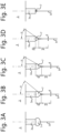
- Different material properties of the spinning material (or spinning solution compositions) and processing parameter settings result in a spinning conus 7 with a specific shape.
- the conus 7 is relatively concave and thin (see e.g. Fig. 3D ), and for microfibres 8 the conus 7 is more convex and wide (see e.g. Fig. 3C ).
- the dimensions of the conus 7 can also be on the edge of producing any stable fibre 8.
- the conus can be over-convex (see Fig. 3A ) or over-concave (see Fig, 3E ) or even the cone can be retracted inside the nozzle tip, which mostly results in an unstable material ejection at the tip of nozzle outlet 3a.
- the shape of the conus 7 during operation of the electrospinning apparatus may be captured using imaging device 4, and processed using image processing techniques implemented in the processing unit 5.
- image processing techniques implemented in the processing unit 5.
- determining a shape of the conus 7 comprises a calibration of the captured image using predetermined dimensions of a reference part of the electrospinning apparatus (such as the nozzle outlet 3a) and edge detection in the captured image.
- the fibre dimensions should be as constant as possible overall or the fibres should have certain dimensional or morphological changes over time.
- Changing the processing settings according to a time-frame works but does not compensate for unforeseen disturbances in material behaviour.
- the present invention method embodiments will overcome these problems.
- a smart-vision camera imaging device 4
- the process can be influenced by e.g. changing the material flow, spinning voltage, spinning distance or the shielding gas flow.
- determining a shape of a conus 7 comprises (dynamically) determining a base point Xb along a primary axis of the electrospinning apparatus, as shown in the cross sectional view of Fig. 3B .
- determining a shape of a conus 7 comprises (dynamically) determining a base point Xb along the centreline of the spinning conus 7.
- the primary axis/ centreline can be defined as the line perpendicular to an end surface of the nozzle outlet 3a, or as a trajectory of the spinning material of the fibre 8 being formed. This can be implemented in the processing unit 5 using image detection and processing algorithms, e.g. using edge detection and/or pixilation techniques.
- the base point Xb is determined using curve matching of an edge of the conus 7 in the captured image.
- Curve matching may be applied in the captured image by finding an apex angle ⁇ as shown in Fig. 3B-D , e.g. using straight lines (i.e. a best match of a triangular conus from an edge of the nozzle outlet 3a with apex angle ⁇ .
- curve matching may be applied using 2 nd or higher order curve matching of a detected edge of the conus 7 in the captured image.
- the jet diameter d (i.e. the diameter of the fibre 8 being formed during operation) is measured at a fixed distance Xd from the determined tip of the conus (i.e. base point Xb).
- the spin wire diameter determination area is determined as a point along the primary axis at a predetermined distance Xd from the base point Xb.
- the predetermined distance Xd is e.g. dependent on the composition of spinning material.
- Using a predetermined distance Xd from the base point Xb gives a stable jet diameter measurement that results in reliable material flow information. It is noted that the information of base point Xb in combination with the cone angle ⁇ provides information about the shape of the conus 7 and its stability.
- the base point Xb (and/or diameter d of the fibre 8) is measured periodically over time.
- the images are taking from a nozzle unit 3 that moves via a translational movement, taking consecutive images by the imaging device 4, may result in subsequent images wherein the apex of conus 7 may vary a bit in relation to the nozzle outlet 3a.
- periodic measurements may also be synchronized to the up and down (translational) movement, e.g. (assuming a fixed position of the imaging device 4) processing an image captured once or twice every up and down cycle.
- all deviations of the conus 7 can be determined and used for feedback. Every material and/or product requires a certain conus 7 shape to result in the required fibre 8 morphology. By using (or learning) the required conus 7 shape as a (time dependent) benchmark, all deviations according to this benchmark can be fed into an algorithm that calculates the required changes in process settings.
- the method further comprises adjusting the operating parameters of the electrospinning apparatus upon detection of a change of the shape of the conus 7.
- adjusting the operating parameters of the electrospinning apparatus upon detection of a change of the shape of the conus 7.
- the fibre 8 formation process will be negatively impacted and requires an adjustment, e.g. by starting or adjusting a gas flow around the conus 7 via gas flow channel 3b.
- the vision feedback detection is used to detect the presence of multiple spin coni 7 out of nozzle outlet 3a.
- the presence of multiple spin coni 7, resulting in multiple fibres 8 being spun during operation, can be a desired or undesired mode of operation of the electrospinning apparatus, and the vision feedback can be used to detect or even stabilize such mode of operation.
- the measurement data derived from the captured images may also be used for quality control or even certification purposes of a product manufactured by the electrospinning apparatus.
- a further method embodiment comprises storing measurement data.
- the present invention relates to an electrospinning apparatus comprising a (fluid) spinning material supply unit 6; a nozzle unit 3 in communication with the spinning material supply unit 6 having a nozzle outlet 3a; a collector unit 1 for collecting a fibre 8 formed during operation of the electrospinning apparatus; a voltage supply unit 2 for applying a voltage difference between the nozzle unit 3 and collector unit 1; an imaging device 4 for capturing an image of a conus 7 and the fibre 8 being formed during operation; and a processing unit 5 connected to the imaging device 4, spinning material supply unit 6 and voltage supply unit 2, wherein the processing unit 5 is arranged to determine a shape of the conus 7, determine from the shape of the conus 7 a spin wire diameter determination area in the captured image, determine an actual spin wire diameter d at the spin wire determination area, and control operation of the electrospinning apparatus based on a difference between the actual spin wire diameter d and a desired spin wire diameter.
- the processing unit 5 is arranged to execute the method according to any one
- the advantage of this electrospinning apparatus is the gain in process reproducibility.
- all variations in mesh and fibre morphology are a huge problem for product performance and certification, which can be addressed by the present invention embodiments.
- the present invention embodiments enable a new level of control on the spinning conus 7 which provides better reproducibility of the process resulting in better quality medical implants and much less scrap of materials (ranging from spun meshes to complete implants).
- the electrospinning apparatus further comprises an environment control unit connected to the processing unit 5 for controlling environmental conditions in a processing chamber of the electrospinning apparatus.
- Environmental control of the actual spinning (fibre forming) space is relevant, but the present invention embodiments also allow a feedback based control with a constant monitoring and adjustment of process parameters when needed.
- the nozzle unit 3 may further comprise a gas flow channel 3b surrounding the nozzle outlet 3a.
- the electrospinning apparatus then further comprises a gas flow control unit connected to the processing unit 5 for controlling an amount of gas flowing through the gas flow channel 3b.
- the electrospinning apparatus further comprises a nozzle position control unit connected to the processing unit 5 for controlling a nozzle protrusion distance W N of the nozzle outlet 3a extending into a processing chamber of electrospinning apparatus. This allows direct influence on the spinning process distance (from nozzle unit 3 to collector unit 1) but also allows to fine tune electrical parameters, i.e. the field strength and field strength distribution between nozzle unit 3 and collector unit 1.
- the nozzle outlet 3a comprises a mixture of multiple fluid flows, e.g. in a coaxial or side-by-side configuration. Vision feedback as described above with reference to other embodiments may be used to control the mixing ratio of each of the individual material flows.
- the electrospinning apparatus may in a further embodiment comprise an injector positioned in the nozzle unit 3, which is connected to the processing unit 5 for control of the injector operation.
- the injector may be applied in a pulse like manner to control material flow of the nozzle outlet 3a, e.g. based on vision feedback using the imaging device 4.
Landscapes
- Engineering & Computer Science (AREA)
- Mechanical Engineering (AREA)
- Textile Engineering (AREA)
- Spinning Methods And Devices For Manufacturing Artificial Fibers (AREA)
Claims (15)
- Verfahren zum Elektrospinnen von Material durch Ausstoßen von Spinnmaterial aus einem Düsenauslass (3a) einer Elektrospinnvorrichtung, wobei der Düsenauslass
(3a) einen Außendurchmesser (EN) aufweist, wobei das Verfahren umfasst- Bestimmen einer Form eines Konus (7) aus flüssigem Spinnmaterial, das aus dem Düsenauslass (3a) austritt, aus einem Bild, das während des Betriebs der Elektrospinnvorrichtung aufgenommen wurde, wobei das Bestimmen einer Form des Konus (7) eine Kalibrierung des aufgenommenen Bildes unter Verwendung vorbestimmter Abmessungen eines Referenzteils (3a) der Elektrospinnvorrichtung und eine Kantenerkennung in dem aufgenommenen Bild umfasst,- Bestimmung eines Spinnfadendurchmesserbestimmungsbereichs in dem aufgenommenen Bild anhand der Form des Konus (7),- Bestimmen eines tatsächlichen Spinnfadendurchmessers (d) in dem Spinnfadendurchmesserbestimmungsbereich, und- Steuern der Betriebsparameter der Elektrospinnvorrichtung auf der Grundlage einer Differenz zwischen dem tatsächlichen Spinnfadendurchmesser (d) und einem gewünschten Spinnfadendurchmesser. - Verfahren nach Anspruch 1, wobei die Betriebsparameter der Elektrospinnvorrichtung eines oder mehrere der folgenden Elemente umfassen:eine Spannung zwischen dem Düsenausgang (3a) und einer Sammeleinheit (1);eine Menge an Spinnmaterial, die durch den Düsenauslass (3a) fließt;Umgebungsbedingungen in einer Prozesskammer der Elektrospinnvorrichtung;eine Gasmenge, die durch einen Gasströmungskanal (3b) fließt, der den Düsenauslass (3a) umgibt;einen Düsenvorsprungsabstand (WN) des Düsenauslasses (3a), der sich in eine Prozesskammer der Elektrospinnvorrichtung erstreckt.
- Verfahren nach einem der Ansprüche 1 - 2, wobei das Bestimmen einer Form eines Konus (7) das Bestimmen eines Basispunktes (Xb) entlang einer Hauptachse der Elektrospinnvorrichtung umfasst.
- Verfahren nach Anspruch 3, wobei die Hauptachse eine Hauptachse des Düsenauslasses (3a) der Elektrospinnvorrichtung, eine Mittellinie des Spinnkonus (7) oder eine Trajektorie des Spinnmaterials einer sich bildenden Faser (8) umfasst.
- Verfahren nach Anspruch 3 oder 4, wobei der Basispunkt (Xb) durch Kurvenanpassung einer Kante des Konus (7) im aufgenommenen Bild bestimmt wird.
- Verfahren nach einem der Ansprüche 3 - 5, wobei der Spinnfadendurchmesserbestimmungsbereich als ein Punkt entlang der Hauptachse in einem vorgegebenen Abstand (Xd) vom Basispunkt (Xb) bestimmt wird.
- Verfahren nach einem der Ansprüche 3 - 5, wobei der Spinnfadendurchmesserbestimmungsbereich als ein Punkt entlang der Hauptachse mit einem vorbestimmten Faktor (i) mal dem Basispunktabstand von einer Kante des Düsenauslasses (3a) in dem aufgenommenen Bild zu dem Basispunkt (Xb) bestimmt wird.
- Verfahren nach einem der Ansprüche 3 - 7, wobei der Basispunkt (Xb) periodisch über die Zeit gemessen wird.
- Verfahren nach einem der Ansprüche 1 - 8, ferner umfassend das Einstellen der Betriebsparameter der Elektrospinnvorrichtung bei Feststellung einer Änderung der Form des Konus (7).
- Verfahren nach einem der Ansprüche 1 - 9, das ferner die Speicherung von Messdaten umfasst.
- Elektrospinnvorrichtung, umfassend:- eine Spinnmaterialzufuhreinheit (6);- eine Düseneinheit (3), die mit der Spinnmaterialzufuhreinheit (6) in Verbindung steht und einen Düsenauslass (3a) aufweist;- eine Sammeleinheit (1) zum Sammeln einer Faser (8), die während des Betriebs der Elektrospinnvorrichtung gebildet wird;- eine Spannungsversorgungseinheit (2) zum Anlegen einer Spannungsdifferenz zwischen der Düseneinheit (3) und der Sammeleinheit (1);- eine Abbildungsvorrichtung (4) zum Erfassen eines Bildes eines Konus (7) aus Fluidspinnmaterial und der während des Betriebs gebildeten Faser (8);- eine Verarbeitungseinheit (5), die mit der Abbildungsvorrichtung (4), der Spinnmaterialzufuhreinheit (6) und der Spannungsversorgungseinheit (2) verbunden ist, wobei die Verarbeitungseinheit (5) so angeordnet ist, um eine Form des Konus (7) durch eine Kalibrierung des aufgenommenen Bildes unter Verwendung vorbestimmter Abmessungen eines Referenzteils (3a) der Elektrospinnvorrichtung und einer Kantenerkennung in dem aufgenommenen Bild zu bestimmen, aus der Form des Konus (7) einen Spinnfadendurchmesserbestimmungsbereich in dem aufgenommenen Bild zu bestimmen, einen tatsächlichen Spinnfadendurchmesser (d) in dem Spinnfadendurchmesserbestimmungsbereich zu bestimmen und Betriebsparameter der Elektrospinnvorrichtung auf der Grundlage einer Differenz zwischen dem tatsächlichen Spinnfadendurchmesser (d) und einem gewünschten Spinnfadendurchmesser zu steuern.
- Elektrospinnvorrichtung nach Anspruch 11, wobei die Verarbeitungseinheit (5) so eingerichtet ist, dass sie das Verfahren nach einem der Ansprüche 1 - 10 ausführt.
- Elektrospinnvorrichtung nach Anspruch 11 oder 12, wobei die Elektrospinnvorrichtung ferner eine mit der Verarbeitungseinheit (5) verbundene Umgebungssteuereinheit zur Steuerung der Umgebungsbedingungen in einer Prozesskammer der Elektrospinnvorrichtung umfasst.
- Elektrospinnvorrichtung nach einem der Ansprüche 11 - 13, wobei die Düseneinheit (3) ferner einen Gasströmungskanal (3b) umfasst, der den Düsenauslass (3a) umgibt, und die Elektrospinnvorrichtung ferner eine Gasströmungssteuereinheit umfasst, die mit der Verarbeitungseinheit (5) verbunden ist, um eine durch den Gasströmungskanal (3b) strömende Gasmenge zu steuern.
- Elektrospinnvorrichtung nach einem der Ansprüche 11 - 14, wobei die Elektrospinnvorrichtung ferner eine Düsenpositionssteuereinheit umfasst, die mit der Verarbeitungseinheit (5) verbunden ist, um einen Düsenvorsprungsabstand (WN) des Düsenauslasses (3a) zu steuern, der sich in eine Prozesskammer der Elektrospinnvorrichtung erstreckt.
Applications Claiming Priority (2)
| Application Number | Priority Date | Filing Date | Title |
|---|---|---|---|
| NL2021681A NL2021681B1 (en) | 2018-09-21 | 2018-09-21 | Electrospinning method and apparatus |
| PCT/NL2019/050631 WO2020060411A1 (en) | 2018-09-21 | 2019-09-20 | Electrospinning method and apparatus |
Publications (2)
| Publication Number | Publication Date |
|---|---|
| EP3853398A1 EP3853398A1 (de) | 2021-07-28 |
| EP3853398B1 true EP3853398B1 (de) | 2024-09-11 |
Family
ID=63834619
Family Applications (1)
| Application Number | Title | Priority Date | Filing Date |
|---|---|---|---|
| EP19828849.0A Active EP3853398B1 (de) | 2018-09-21 | 2019-09-20 | Elektrospinnverfahren und vorrichtung |
Country Status (7)
| Country | Link |
|---|---|
| US (1) | US11926928B2 (de) |
| EP (1) | EP3853398B1 (de) |
| CN (1) | CN113015825B (de) |
| ES (1) | ES2996901T3 (de) |
| NL (1) | NL2021681B1 (de) |
| PL (1) | PL3853398T3 (de) |
| WO (1) | WO2020060411A1 (de) |
Families Citing this family (1)
| Publication number | Priority date | Publication date | Assignee | Title |
|---|---|---|---|---|
| WO2021006813A1 (en) * | 2019-07-09 | 2021-01-14 | Agency For Science, Technology And Research | An apparatus and a method of drawing a fibre |
Family Cites Families (17)
| Publication number | Priority date | Publication date | Assignee | Title |
|---|---|---|---|---|
| DE3506924A1 (de) * | 1985-02-27 | 1986-09-04 | Reifenhäuser GmbH & Co Maschinenfabrik, 5210 Troisdorf | Einrichtung fuer das spinnen von monofilfaeden aus thermoplastischem kunststoff |
| DE3521571C1 (de) * | 1985-06-15 | 1986-10-09 | Reifenhäuser GmbH & Co Maschinenfabrik, 5210 Troisdorf | Verfahren und Vorrichtung fuer die Herstellung von Monofilfaeden geringer Dickentoleranz aus thermoplastischem Kunststoff |
| KR100836274B1 (ko) | 2007-05-25 | 2008-06-10 | 한국기계연구원 | 멀티 노즐 전기 방사 장치의 모니터링과 보수 장치 및 그를이용한 모니터링과 보수 방법 |
| WO2012097229A2 (en) * | 2011-01-14 | 2012-07-19 | Neograft Technologies, Inc. | Apparatus for creating graft devices |
| CN102582293B (zh) * | 2012-02-29 | 2014-07-23 | 厦门大学 | 电纺直写闭环控制系统及控制方法 |
| CN103465628B (zh) * | 2013-09-03 | 2015-10-28 | 华中科技大学 | 一种静电喷印纳米纤维直径闭环控制方法及装置 |
| US20150073551A1 (en) * | 2013-09-10 | 2015-03-12 | The Uab Research Foundation | Biomimetic tissue graft for ligament replacement |
| EP3089704A4 (de) * | 2013-12-31 | 2017-08-16 | Neograft Technologies, Inc. | Selbstdiagnostische transplantatherstellungssysteme und zugehörige verfahren |
| CN203782282U (zh) * | 2014-03-18 | 2014-08-20 | 广东工业大学 | 一种静电纺丝装置 |
| CN104309338B (zh) * | 2014-10-17 | 2017-01-11 | 华中科技大学 | 一种电纺丝直写工艺闭环控制方法 |
| KR101688817B1 (ko) * | 2014-12-31 | 2016-12-22 | 주식회사 에이앤에프 | 전기방사 방식 패턴 형성 장치 |
| KR101622054B1 (ko) | 2014-12-31 | 2016-05-17 | (재)한국섬유기계연구원 | 전기방사 기법을 활용한 입체형상 나노섬유 제조장치 및 그 방법 |
| NL2016652B1 (en) | 2016-04-21 | 2017-11-16 | Innovative Mechanical Engineering Tech B V | Electrospinning device and method. |
| CN105839202A (zh) * | 2016-04-23 | 2016-08-10 | 北京化工大学 | 一种静电纺聚丙烯腈纤维直径与结构的控制方法 |
| CN108754635B (zh) * | 2017-01-13 | 2019-11-12 | 大连民族大学 | 一种静电纺丝设备和方法 |
| CN107932894B (zh) | 2017-12-22 | 2024-03-15 | 青岛理工大学 | 一种高精度电场驱动喷射沉积3d打印机及其工作方法 |
| CN108221068B (zh) * | 2018-02-08 | 2019-12-10 | 广东工业大学 | 基于机器视觉的近场电纺喷印效果在线检测及其调控方法 |
-
2018
- 2018-09-21 NL NL2021681A patent/NL2021681B1/en active
-
2019
- 2019-09-20 US US17/277,739 patent/US11926928B2/en active Active
- 2019-09-20 WO PCT/NL2019/050631 patent/WO2020060411A1/en not_active Ceased
- 2019-09-20 CN CN201980074761.2A patent/CN113015825B/zh active Active
- 2019-09-20 PL PL19828849.0T patent/PL3853398T3/pl unknown
- 2019-09-20 EP EP19828849.0A patent/EP3853398B1/de active Active
- 2019-09-20 ES ES19828849T patent/ES2996901T3/es active Active
Also Published As
| Publication number | Publication date |
|---|---|
| WO2020060411A1 (en) | 2020-03-26 |
| CN113015825A (zh) | 2021-06-22 |
| CN113015825B (zh) | 2024-02-06 |
| US11926928B2 (en) | 2024-03-12 |
| PL3853398T3 (pl) | 2025-02-10 |
| EP3853398A1 (de) | 2021-07-28 |
| ES2996901T3 (en) | 2025-02-13 |
| NL2021681B1 (en) | 2020-05-07 |
| US20220112626A1 (en) | 2022-04-14 |
Similar Documents
| Publication | Publication Date | Title |
|---|---|---|
| EP1948854B1 (de) | Elektrohydrodynamisches drucken und produzieren | |
| You et al. | Electric field manipulation for deposition control in near-field electrospinning | |
| US12397497B2 (en) | Printing device and method | |
| Wang et al. | Introduction to electrospinning | |
| Liu et al. | Influence of electrohydrodynamic jetting parameters on the morphology of PCL scaffolds | |
| Xia et al. | Scaling laws for transition from varicose to whipping instabilities in electrohydrodynamic jetting | |
| EP3853398B1 (de) | Elektrospinnverfahren und vorrichtung | |
| DK2758243T3 (en) | Method and device for extracting homogeneous ink for inkjet devices | |
| JP2016053224A (ja) | ナノファイバ製造装置、及び、ナノファイバ製造方法 | |
| US8500431B2 (en) | Electrospinning control for precision electrospinning of polymer fibers | |
| JP6672198B2 (ja) | ナノファイバ製造方法及び装置 | |
| Bu et al. | Process optimization of mechano-electrospinning by response surface methodology | |
| US12162207B2 (en) | Device and method for determining the speed of printing of a fiber and the length of a printed fiber | |
| US20260028753A1 (en) | Electrospinning systems for mass production of nanofibers | |
| Phung et al. | A Counter Electrode Integrated Electrohydrodynamic Head with Capability of Real-TimeMonitoring. | |
| Sun et al. | Electrohydrodynamic Printing Process Monitoring for Diverse Microstructure Bioscaffold Fabrication | |
| US12180614B2 (en) | Device for producing electrospun short polymer fibres | |
| EP4565732A1 (de) | Elektrospinning-systeme zur massenproduktion von nanofasern | |
| US20240001606A1 (en) | Electro-spinning/writing system and corresponding method | |
| Minařík et al. | Close Electrohydrodynamic Fiber Deposition using a Partially Coated Glass Collector | |
| JP2017193816A (ja) | ナノファイバ製造装置、及び、ナノファイバ製造方法 |
Legal Events
| Date | Code | Title | Description |
|---|---|---|---|
| STAA | Information on the status of an ep patent application or granted ep patent |
Free format text: STATUS: UNKNOWN |
|
| STAA | Information on the status of an ep patent application or granted ep patent |
Free format text: STATUS: THE INTERNATIONAL PUBLICATION HAS BEEN MADE |
|
| PUAI | Public reference made under article 153(3) epc to a published international application that has entered the european phase |
Free format text: ORIGINAL CODE: 0009012 |
|
| STAA | Information on the status of an ep patent application or granted ep patent |
Free format text: STATUS: REQUEST FOR EXAMINATION WAS MADE |
|
| 17P | Request for examination filed |
Effective date: 20210419 |
|
| AK | Designated contracting states |
Kind code of ref document: A1 Designated state(s): AL AT BE BG CH CY CZ DE DK EE ES FI FR GB GR HR HU IE IS IT LI LT LU LV MC MK MT NL NO PL PT RO RS SE SI SK SM TR |
|
| DAV | Request for validation of the european patent (deleted) | ||
| DAX | Request for extension of the european patent (deleted) | ||
| GRAP | Despatch of communication of intention to grant a patent |
Free format text: ORIGINAL CODE: EPIDOSNIGR1 |
|
| STAA | Information on the status of an ep patent application or granted ep patent |
Free format text: STATUS: GRANT OF PATENT IS INTENDED |
|
| INTG | Intention to grant announced |
Effective date: 20240417 |
|
| GRAS | Grant fee paid |
Free format text: ORIGINAL CODE: EPIDOSNIGR3 |
|
| GRAA | (expected) grant |
Free format text: ORIGINAL CODE: 0009210 |
|
| STAA | Information on the status of an ep patent application or granted ep patent |
Free format text: STATUS: THE PATENT HAS BEEN GRANTED |
|
| AK | Designated contracting states |
Kind code of ref document: B1 Designated state(s): AL AT BE BG CH CY CZ DE DK EE ES FI FR GB GR HR HU IE IS IT LI LT LU LV MC MK MT NL NO PL PT RO RS SE SI SK SM TR |
|
| P01 | Opt-out of the competence of the unified patent court (upc) registered |
Free format text: CASE NUMBER: APP_44785/2024 Effective date: 20240801 |
|
| REG | Reference to a national code |
Ref country code: GB Ref legal event code: FG4D |
|
| REG | Reference to a national code |
Ref country code: CH Ref legal event code: EP |
|
| REG | Reference to a national code |
Ref country code: DE Ref legal event code: R096 Ref document number: 602019058828 Country of ref document: DE |
|
| REG | Reference to a national code |
Ref country code: IE Ref legal event code: FG4D |
|
| REG | Reference to a national code |
Ref country code: NL Ref legal event code: FP |
|
| REG | Reference to a national code |
Ref country code: LT Ref legal event code: MG9D |
|
| PG25 | Lapsed in a contracting state [announced via postgrant information from national office to epo] |
Ref country code: NO Free format text: LAPSE BECAUSE OF FAILURE TO SUBMIT A TRANSLATION OF THE DESCRIPTION OR TO PAY THE FEE WITHIN THE PRESCRIBED TIME-LIMIT Effective date: 20241211 |
|
| PG25 | Lapsed in a contracting state [announced via postgrant information from national office to epo] |
Ref country code: GR Free format text: LAPSE BECAUSE OF FAILURE TO SUBMIT A TRANSLATION OF THE DESCRIPTION OR TO PAY THE FEE WITHIN THE PRESCRIBED TIME-LIMIT Effective date: 20241212 Ref country code: FI Free format text: LAPSE BECAUSE OF FAILURE TO SUBMIT A TRANSLATION OF THE DESCRIPTION OR TO PAY THE FEE WITHIN THE PRESCRIBED TIME-LIMIT Effective date: 20240911 |
|
| PG25 | Lapsed in a contracting state [announced via postgrant information from national office to epo] |
Ref country code: BG Free format text: LAPSE BECAUSE OF FAILURE TO SUBMIT A TRANSLATION OF THE DESCRIPTION OR TO PAY THE FEE WITHIN THE PRESCRIBED TIME-LIMIT Effective date: 20240911 |
|
| PG25 | Lapsed in a contracting state [announced via postgrant information from national office to epo] |
Ref country code: LV Free format text: LAPSE BECAUSE OF FAILURE TO SUBMIT A TRANSLATION OF THE DESCRIPTION OR TO PAY THE FEE WITHIN THE PRESCRIBED TIME-LIMIT Effective date: 20240911 |
|
| PG25 | Lapsed in a contracting state [announced via postgrant information from national office to epo] |
Ref country code: HR Free format text: LAPSE BECAUSE OF FAILURE TO SUBMIT A TRANSLATION OF THE DESCRIPTION OR TO PAY THE FEE WITHIN THE PRESCRIBED TIME-LIMIT Effective date: 20240911 |
|
| PG25 | Lapsed in a contracting state [announced via postgrant information from national office to epo] |
Ref country code: RS Free format text: LAPSE BECAUSE OF FAILURE TO SUBMIT A TRANSLATION OF THE DESCRIPTION OR TO PAY THE FEE WITHIN THE PRESCRIBED TIME-LIMIT Effective date: 20241211 |
|
| PG25 | Lapsed in a contracting state [announced via postgrant information from national office to epo] |
Ref country code: RS Free format text: LAPSE BECAUSE OF FAILURE TO SUBMIT A TRANSLATION OF THE DESCRIPTION OR TO PAY THE FEE WITHIN THE PRESCRIBED TIME-LIMIT Effective date: 20241211 Ref country code: NO Free format text: LAPSE BECAUSE OF FAILURE TO SUBMIT A TRANSLATION OF THE DESCRIPTION OR TO PAY THE FEE WITHIN THE PRESCRIBED TIME-LIMIT Effective date: 20241211 Ref country code: LV Free format text: LAPSE BECAUSE OF FAILURE TO SUBMIT A TRANSLATION OF THE DESCRIPTION OR TO PAY THE FEE WITHIN THE PRESCRIBED TIME-LIMIT Effective date: 20240911 Ref country code: HR Free format text: LAPSE BECAUSE OF FAILURE TO SUBMIT A TRANSLATION OF THE DESCRIPTION OR TO PAY THE FEE WITHIN THE PRESCRIBED TIME-LIMIT Effective date: 20240911 Ref country code: GR Free format text: LAPSE BECAUSE OF FAILURE TO SUBMIT A TRANSLATION OF THE DESCRIPTION OR TO PAY THE FEE WITHIN THE PRESCRIBED TIME-LIMIT Effective date: 20241212 Ref country code: FI Free format text: LAPSE BECAUSE OF FAILURE TO SUBMIT A TRANSLATION OF THE DESCRIPTION OR TO PAY THE FEE WITHIN THE PRESCRIBED TIME-LIMIT Effective date: 20240911 Ref country code: BG Free format text: LAPSE BECAUSE OF FAILURE TO SUBMIT A TRANSLATION OF THE DESCRIPTION OR TO PAY THE FEE WITHIN THE PRESCRIBED TIME-LIMIT Effective date: 20240911 |
|
| REG | Reference to a national code |
Ref country code: ES Ref legal event code: FG2A Ref document number: 2996901 Country of ref document: ES Kind code of ref document: T3 Effective date: 20250213 |
|
| REG | Reference to a national code |
Ref country code: AT Ref legal event code: MK05 Ref document number: 1722743 Country of ref document: AT Kind code of ref document: T Effective date: 20240911 |
|
| PG25 | Lapsed in a contracting state [announced via postgrant information from national office to epo] |
Ref country code: IS Free format text: LAPSE BECAUSE OF FAILURE TO SUBMIT A TRANSLATION OF THE DESCRIPTION OR TO PAY THE FEE WITHIN THE PRESCRIBED TIME-LIMIT Effective date: 20250111 Ref country code: PT Free format text: LAPSE BECAUSE OF FAILURE TO SUBMIT A TRANSLATION OF THE DESCRIPTION OR TO PAY THE FEE WITHIN THE PRESCRIBED TIME-LIMIT Effective date: 20250113 |
|
| PG25 | Lapsed in a contracting state [announced via postgrant information from national office to epo] |
Ref country code: RO Free format text: LAPSE BECAUSE OF FAILURE TO SUBMIT A TRANSLATION OF THE DESCRIPTION OR TO PAY THE FEE WITHIN THE PRESCRIBED TIME-LIMIT Effective date: 20240911 Ref country code: SM Free format text: LAPSE BECAUSE OF FAILURE TO SUBMIT A TRANSLATION OF THE DESCRIPTION OR TO PAY THE FEE WITHIN THE PRESCRIBED TIME-LIMIT Effective date: 20240911 |
|
| PG25 | Lapsed in a contracting state [announced via postgrant information from national office to epo] |
Ref country code: EE Free format text: LAPSE BECAUSE OF FAILURE TO SUBMIT A TRANSLATION OF THE DESCRIPTION OR TO PAY THE FEE WITHIN THE PRESCRIBED TIME-LIMIT Effective date: 20240911 Ref country code: AT Free format text: LAPSE BECAUSE OF FAILURE TO SUBMIT A TRANSLATION OF THE DESCRIPTION OR TO PAY THE FEE WITHIN THE PRESCRIBED TIME-LIMIT Effective date: 20240911 |
|
| PG25 | Lapsed in a contracting state [announced via postgrant information from national office to epo] |
Ref country code: SK Free format text: LAPSE BECAUSE OF FAILURE TO SUBMIT A TRANSLATION OF THE DESCRIPTION OR TO PAY THE FEE WITHIN THE PRESCRIBED TIME-LIMIT Effective date: 20240911 |
|
| REG | Reference to a national code |
Ref country code: CH Ref legal event code: PL |
|
| PG25 | Lapsed in a contracting state [announced via postgrant information from national office to epo] |
Ref country code: LU Free format text: LAPSE BECAUSE OF NON-PAYMENT OF DUE FEES Effective date: 20240920 |
|
| REG | Reference to a national code |
Ref country code: DE Ref legal event code: R097 Ref document number: 602019058828 Country of ref document: DE |
|
| PG25 | Lapsed in a contracting state [announced via postgrant information from national office to epo] |
Ref country code: MC Free format text: LAPSE BECAUSE OF FAILURE TO SUBMIT A TRANSLATION OF THE DESCRIPTION OR TO PAY THE FEE WITHIN THE PRESCRIBED TIME-LIMIT Effective date: 20240911 |
|
| PG25 | Lapsed in a contracting state [announced via postgrant information from national office to epo] |
Ref country code: DK Free format text: LAPSE BECAUSE OF FAILURE TO SUBMIT A TRANSLATION OF THE DESCRIPTION OR TO PAY THE FEE WITHIN THE PRESCRIBED TIME-LIMIT Effective date: 20240911 |
|
| PLBE | No opposition filed within time limit |
Free format text: ORIGINAL CODE: 0009261 |
|
| STAA | Information on the status of an ep patent application or granted ep patent |
Free format text: STATUS: NO OPPOSITION FILED WITHIN TIME LIMIT |
|
| PG25 | Lapsed in a contracting state [announced via postgrant information from national office to epo] |
Ref country code: CH Free format text: LAPSE BECAUSE OF NON-PAYMENT OF DUE FEES Effective date: 20240930 |
|
| 26N | No opposition filed |
Effective date: 20250612 |
|
| PG25 | Lapsed in a contracting state [announced via postgrant information from national office to epo] |
Ref country code: SE Free format text: LAPSE BECAUSE OF FAILURE TO SUBMIT A TRANSLATION OF THE DESCRIPTION OR TO PAY THE FEE WITHIN THE PRESCRIBED TIME-LIMIT Effective date: 20240911 |
|
| PGFP | Annual fee paid to national office [announced via postgrant information from national office to epo] |
Ref country code: DE Payment date: 20250926 Year of fee payment: 7 |
|
| PGFP | Annual fee paid to national office [announced via postgrant information from national office to epo] |
Ref country code: PL Payment date: 20250915 Year of fee payment: 7 Ref country code: NL Payment date: 20250909 Year of fee payment: 7 Ref country code: IT Payment date: 20250922 Year of fee payment: 7 |
|
| PGFP | Annual fee paid to national office [announced via postgrant information from national office to epo] |
Ref country code: BE Payment date: 20250925 Year of fee payment: 7 Ref country code: GB Payment date: 20250923 Year of fee payment: 7 |
|
| PGFP | Annual fee paid to national office [announced via postgrant information from national office to epo] |
Ref country code: FR Payment date: 20250925 Year of fee payment: 7 |
|
| PGFP | Annual fee paid to national office [announced via postgrant information from national office to epo] |
Ref country code: IE Payment date: 20250917 Year of fee payment: 7 Ref country code: CZ Payment date: 20250904 Year of fee payment: 7 |
|
| PG25 | Lapsed in a contracting state [announced via postgrant information from national office to epo] |
Ref country code: CY Free format text: LAPSE BECAUSE OF FAILURE TO SUBMIT A TRANSLATION OF THE DESCRIPTION OR TO PAY THE FEE WITHIN THE PRESCRIBED TIME-LIMIT; INVALID AB INITIO Effective date: 20190920 |
|
| PGFP | Annual fee paid to national office [announced via postgrant information from national office to epo] |
Ref country code: ES Payment date: 20251015 Year of fee payment: 7 |