EP3853176B1 - Verfahren zur entfernung von inertgasen aus flüssigem ammoniak - Google Patents
Verfahren zur entfernung von inertgasen aus flüssigem ammoniak Download PDFInfo
- Publication number
- EP3853176B1 EP3853176B1 EP19769763.4A EP19769763A EP3853176B1 EP 3853176 B1 EP3853176 B1 EP 3853176B1 EP 19769763 A EP19769763 A EP 19769763A EP 3853176 B1 EP3853176 B1 EP 3853176B1
- Authority
- EP
- European Patent Office
- Prior art keywords
- ammonia
- gases
- liquid
- plant
- stream
- Prior art date
- Legal status (The legal status is an assumption and is not a legal conclusion. Google has not performed a legal analysis and makes no representation as to the accuracy of the status listed.)
- Active
Links
Images
Classifications
-
- B—PERFORMING OPERATIONS; TRANSPORTING
- B01—PHYSICAL OR CHEMICAL PROCESSES OR APPARATUS IN GENERAL
- B01D—SEPARATION
- B01D1/00—Evaporating
- B01D1/28—Evaporating with vapour compression
- B01D1/2887—The compressor is integrated in the evaporation apparatus
-
- B—PERFORMING OPERATIONS; TRANSPORTING
- B01—PHYSICAL OR CHEMICAL PROCESSES OR APPARATUS IN GENERAL
- B01D—SEPARATION
- B01D19/00—Degasification of liquids
- B01D19/0036—Flash degasification
-
- B—PERFORMING OPERATIONS; TRANSPORTING
- B01—PHYSICAL OR CHEMICAL PROCESSES OR APPARATUS IN GENERAL
- B01D—SEPARATION
- B01D19/00—Degasification of liquids
- B01D19/0073—Degasification of liquids by a method not covered by groups B01D19/0005 - B01D19/0042
-
- B—PERFORMING OPERATIONS; TRANSPORTING
- B01—PHYSICAL OR CHEMICAL PROCESSES OR APPARATUS IN GENERAL
- B01D—SEPARATION
- B01D5/00—Condensation of vapours; Recovering volatile solvents by condensation
- B01D5/0057—Condensation of vapours; Recovering volatile solvents by condensation in combination with other processes
- B01D5/006—Condensation of vapours; Recovering volatile solvents by condensation in combination with other processes with evaporation or distillation
-
- B—PERFORMING OPERATIONS; TRANSPORTING
- B01—PHYSICAL OR CHEMICAL PROCESSES OR APPARATUS IN GENERAL
- B01D—SEPARATION
- B01D5/00—Condensation of vapours; Recovering volatile solvents by condensation
- B01D5/0057—Condensation of vapours; Recovering volatile solvents by condensation in combination with other processes
- B01D5/0069—Condensation of vapours; Recovering volatile solvents by condensation in combination with other processes with degasification or deaeration
-
- B—PERFORMING OPERATIONS; TRANSPORTING
- B01—PHYSICAL OR CHEMICAL PROCESSES OR APPARATUS IN GENERAL
- B01D—SEPARATION
- B01D5/00—Condensation of vapours; Recovering volatile solvents by condensation
- B01D5/0078—Condensation of vapours; Recovering volatile solvents by condensation characterised by auxiliary systems or arrangements
- B01D5/0093—Removing and treatment of non condensable gases
-
- C—CHEMISTRY; METALLURGY
- C01—INORGANIC CHEMISTRY
- C01C—AMMONIA; CYANOGEN; COMPOUNDS THEREOF
- C01C1/00—Ammonia; Compounds thereof
- C01C1/02—Preparation, purification or separation of ammonia
- C01C1/024—Purification
-
- Y—GENERAL TAGGING OF NEW TECHNOLOGICAL DEVELOPMENTS; GENERAL TAGGING OF CROSS-SECTIONAL TECHNOLOGIES SPANNING OVER SEVERAL SECTIONS OF THE IPC; TECHNICAL SUBJECTS COVERED BY FORMER USPC CROSS-REFERENCE ART COLLECTIONS [XRACs] AND DIGESTS
- Y02—TECHNOLOGIES OR APPLICATIONS FOR MITIGATION OR ADAPTATION AGAINST CLIMATE CHANGE
- Y02P—CLIMATE CHANGE MITIGATION TECHNOLOGIES IN THE PRODUCTION OR PROCESSING OF GOODS
- Y02P20/00—Technologies relating to chemical industry
- Y02P20/50—Improvements relating to the production of bulk chemicals
Definitions
- the present invention relates to a process for removing inert gases dissolved in liquid ammonia.
- the synthesis gas typically contains hydrogen and nitrogen, as well as inert gases such as methane and noble gases, which impair the ammonia yield.
- fresh synthesis gas is typically first compressed to high pressure in several stages. The compressed, fresh synthesis gas is then fed into a cycle that passes through one or more catalyst-filled reactors where ammonia is produced.
- the cycle incorporates a separation system to remove the produced ammonia from the cycle in liquid form.
- the inert gases are only soluble in ammonia in low concentrations and are therefore only removed to a small extent along with the ammonia.
- these conventional processes continually remove a portion of the gas circulating in the circuit as purge gas. Residual ammonia is then washed out of this purge gas.
- Hydrogen and, if applicable, nitrogen are separated and recovered, for example via membranes or by decomposition at low temperatures. The remaining inert gases, in particular methane, argon and helium are discarded or used for other purposes, in particular for heating purposes.
- the recovered hydrogen and, if applicable, also the recovered nitrogen are mixed with the fresh synthesis gas before compression and used in this way.
- DE 100 57 863 A1 discloses a process for producing ammonia from fresh synthesis gas, which contains inert components besides hydrogen and nitrogen, in at least two reaction systems.
- the synthesis of ammonia from synthesis gas takes place sequentially in different synthesis systems.
- Inert gas components are separated and discharged via a purge gas stream.
- Inert gases or "inerts" in the production of ammonia are those components that behave inertly during the conversion of hydrogen and nitrogen to ammonia. These inert gases include, for example, the noble gases and methane.
- ammonia synthesis a gas mixture is created from the synthesis gas in the reactor.
- This gas mixture contains the unreacted hydrogen and nitrogen, the ammonia formed, and the inert gases.
- the produced ammonia is in gaseous form.
- the condensation of ammonia is favored by a high synthesis pressure, a high ammonia concentration, and a low temperature.
- a high ammonia concentration can be achieved with large catalyst volumes and low inert gas concentrations.
- a high synthesis pressure requires corresponding energy expenditure for the synthesis gas compression, and a low cooling temperature requires appropriate cooling devices for the gas circulating in the cycle.
- ammonia can be produced in several reaction systems connected in series. In this case, too, the ammonia is condensed and discharged from the synthesis cycle as liquid ammonia.
- liquid ammonia produced during ammonia synthesis using conventional processes usually still contains dissolved gases, which can be disruptive, for example, during subsequent urea synthesis, as they can lead to the formation of explosive exhaust gases in the urea plant.
- dissolved gases can be disruptive, for example, during subsequent urea synthesis, as they can lead to the formation of explosive exhaust gases in the urea plant.
- the object of the present invention is therefore to provide an effective process for removing dissolved inert gases from the liquid ammonia produced during ammonia synthesis.
- the liquid ammonia with the inert gases dissolved therein is first evaporated in at least one first process step, then compressed in at least one second process step and subsequently condensed again in at least one third process step.
- the gases dissolved in the liquid ammonia fed into the system are primarily inert gases as defined above, i.e., gases that behave neutrally during ammonia synthesis, such as, in particular, the noble gases helium, argon, and methane.
- gases that behave neutrally during ammonia synthesis such as, in particular, the noble gases helium, argon, and methane.
- small amounts of hydrogen and nitrogen, the reactant gases of ammonia synthesis may also be dissolved in the ammonia after synthesis.
- These gases do not fall under the term "inert gases" (and thus under claim 1), but can also be removed from the liquid ammonia using the procedure according to the invention.
- the inert gases, as well as hydrogen and nitrogen are generally present in the liquid ammonia in quantities that are, for example, in the range of no more than approximately a few hundred ppm.
- a particular advantage of the process according to the invention is that a product stream of "warm" liquid ammonia is obtained, freed from inert gases (and other gases), which is under increased pressure compared to normal pressure and is thus suitable for immediate use in processes requiring pure liquid pressurized ammonia, for example, for urea synthesis or the like.
- the ammonia were first cooled, for example, below the boiling point, which for ammonia is -33 °C, and expanded to normal pressure, in order to then store it as liquid ammonia at low temperatures in tanks, it would first have to be reheated and compressed for further processing of the type mentioned. This would require energy, so that the process according to the invention leads to significant energy savings.
- the process according to the invention provides the ammonia with a higher degree of purity than is possible with Ammonia synthesis usually occurs, so that further purification steps to remove disturbing residual amounts of inert gases dissolved in the liquid ammonia are not required when the ammonia resulting from ammonia synthesis is processed directly.
- a preferred development of the invention provides that the condensation of the ammonia in the third process step takes place at an elevated pressure and at a temperature above +10°C, preferably at a temperature in the range of +10°C to +30°C.
- the exact temperature of the warm liquid ammonia purified of dissolved gases depends on the temperature of the cooling water by means of which the condensation of the ammonia takes place in the third process step.
- Cold liquid ammonia is understood to be liquid ammonia that is either below the boiling point of -33 °C and thus liquid at atmospheric pressure, or at somewhat higher temperatures, for example, between -33 °C and +10 °C and correspondingly increased pressure.
- This "cold” liquid ammonia within the meaning of the present invention, thus exists at a lower temperature than the above-mentioned "warm” liquid ammonia.
- the heat absorbed by the ammonia in the evaporation process step is used to cool a process stream.
- the evaporation process step in which heat is extracted from the environment, can thus be used, for example, to cool process streams outside the system, for which no separate coolant needs to be provided.
- the heat absorbed by the ammonia in the evaporation process step is used to condense ammonia in an ammonia synthesis plant.
- the evaporation process step according to the invention allows for coupling with the condensation step of ammonia in an ammonia synthesis plant. Both process steps can be linked in an energetically advantageous manner.
- the condensation of the ammonia in the third process step takes place at an elevated pressure in the range of, for example, approximately 10 bar to approximately 30 bar, preferably in the range of approximately 15 bar to approximately 25 bar.
- the pressure required here depends, as mentioned above, on the respective temperature at which the ammonia is condensed.
- the evaporated ammonia is compressed after evaporation together with the gases previously dissolved in the ammonia. This means that the dissolved gases are removed only subsequently in the ammonia condenser.
- the compressed ammonia is condensed with the aid of cooling water after compression.
- the condensation temperature therefore depends on the temperature of the cooling water used.
- a preferred development of the invention provides that the gases insoluble in the ammonia during the condensation of the ammonia are withdrawn from the device used for condensation.
- the temperature and pressure are preferably selected such that the ammonia is just condensing.
- the solubility of the gases in the liquid ammonia is at its lowest, so that the gases are then no longer dissolved in the ammonia and are therefore present as gases separated from the liquid ammonia and can be withdrawn.
- the gases extracted in the previously described process are recycled. This is useful, for example, if these gases still contain portions of the reactant gases hydrogen and/or nitrogen, which can then be recycled to the ammonia production plant and used there to produce further ammonia.
- a first substream of a reactant stream of liquid ammonia is evaporated in the first process step, then compressed, subsequently condensed, and discharged from the system as ammonia freed of gases, particularly inert gases, in a liquid, pressurized warm stream.
- a second substream is branched off from the reactant stream and initially branched off from the system as a liquid cold stream without further processing.
- the "warm" substream is generally fed to a plant in which further processing of the ammonia is planned, for example, a urea synthesis plant.
- the second partial stream which is diverted from the reactant stream, can, however, initially be temporarily stored as a cold stream of liquid ammonia and therefore does not need to undergo the purification steps of evaporation, compression, and condensation provided by the invention.
- This second partial stream can be temporarily stored cold, for example, in a tank.
- this partial stream is expanded and cooled below the ammonia's condensation temperature of -33 °C.
- the gases dissolved in the ammonia degas, so that the purification process according to the invention for removing gases dissolved in the ammonia is not required for this partial stream.
- a portion of the ammonia for which it is known from the outset that it will not be further processed at warm temperatures and at elevated pressure, but for which intermediate cold storage is planned can be diverted as a cold partial stream.
- the first warm partial stream of ammonia which is condensed and freed from the inert gases, represents a main stream of the ammonia discharged from the system.
- the warm partial stream which constitutes the main stream, can, for example, constitute 70% to 100%, preferably up to about 90%, of the ammonia processed in the system, so that the partial stream which is not further processed and is discharged as a cold partial stream, for example, constitutes a smaller partial stream of 0% to 30%, preferably of at least about 10%, of the total reactant stream fed to the plant.
- the present invention further relates to a plant for removing inert gases dissolved in liquid ammonia, comprising at least one line for supplying liquid ammonia to at least one ammonia evaporator, at least one ammonia compressor operatively connected to this ammonia evaporator, at least one ammonia condenser operatively connected to the ammonia compressor with means for discharging a stream of inert gases separated in the ammonia condenser, and at least one collecting container operatively connected to the ammonia condenser for receiving liquid ammonia freed from inert gases.
- the line for supplying liquid ammonia is connected to an outlet line of a plant for producing ammonia or is such an outlet line.
- ammonia can be freed from the gases dissolved in the ammonia and thus further purified in the plant according to the invention directly from the production process without intermediate cooling, under the pressure and at the temperature at which it is produced in this production process.
- the plant comprises a container for receiving ammonia contaminated with inert gases, from which a first line leads to the ammonia evaporator, wherein at least one branch line branches off from this first line, by means of which a partial flow of liquid ammonia is discharged from the plant.
- a container for receiving ammonia contaminated with inert gases from which a first line leads to the ammonia evaporator, wherein at least one branch line branches off from this first line, by means of which a partial flow of liquid ammonia is discharged from the plant.
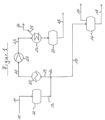
- Figure 1 a schematically simplified flow diagram of an exemplary system according to the invention.
- FIG. 1 shows a simplified flow diagram of an exemplary plant according to the invention for removing inert gases dissolved in liquid ammonia from the ammonia.
- the illustration is highly simplified schematically, and only the plant components essential to the present invention are shown.
- a process stream 10 of liquid ammonia which contains dissolved gases such as inert gases and optionally other gases and which originates from a plant for the production of ammonia (this ammonia plant is not shown here), is fed via line 11 to a tank 12 in which liquid ammonia can be temporarily stored if necessary prior to the processing according to the invention.
- Liquid ammonia is discharged from this tank 12 via line 13, which splits downstream at a branch 14, so that two partial streams of liquid ammonia are created.
- a first, smaller partial stream flows via line 15 and is fed as a cold partial stream of liquid ammonia to another tank 16.
- the ammonia can be expanded to atmospheric pressure, whereby gases dissolved in the ammonia can outgas and be discharged via line 17.
- the cold liquid ammonia can be discharged via line 18 and, for example, exported or, after heating and compression, fed to a urea plant via line 17.
- the majority of the partial stream is processed according to the process according to the invention and fed to an ammonia evaporator 20 via line 19.
- the process stream is fed to an ammonia compressor 22 via line 21.
- the process stream passes via line 23 to an ammonia condenser 24.
- the compressed ammonia can be condensed with the aid of cooling water.
- the temperature of the ammonia after condensation is, for example, approximately 30 °C, and the condensed liquid ammonia is under correspondingly increased pressure. During this condensation, the gases to be separated from the ammonia escape and can therefore be withdrawn from the condenser in gaseous form via line 25 and discharged from the plant via outlet line 26.
- the purified liquid ammonia can, if necessary, be temporarily stored under pressure at the appropriate temperature in a tank 27. From this tank, a warm stream of liquid pressurized ammonia can then be fed to another plant via line 28. , for example, a urea plant. Intermediate storage in tank 27 can also be omitted if, for example, there is an immediate need for a corresponding amount of "warm" liquid ammonia for a further process in which the ammonia is required as a warm, pressurized stream and can thus be processed directly without intermediate cooling.
- the advantage of the process according to the invention is that it can be used to produce a purified "warm” partial stream of liquid ammonia on the one hand and, if necessary, also a “cold” partial stream of liquid ammonia, which does not require any separate treatment.
Landscapes
- Chemical & Material Sciences (AREA)
- Chemical Kinetics & Catalysis (AREA)
- Organic Chemistry (AREA)
- Analytical Chemistry (AREA)
- Inorganic Chemistry (AREA)
- Organic Low-Molecular-Weight Compounds And Preparation Thereof (AREA)
- Industrial Gases (AREA)
Description
- Die vorliegende Erfindung betrifft ein Verfahren zur Entfernung von in flüssigem Ammoniak gelösten Inertgasen.
- Bei der Herstellung von Ammoniak enthält das Synthesegas neben Wasserstoff und Stickstoff zusätzlich üblicherweise Inertgase wie Methan und Edelgase, welche die Ausbeute an Ammoniak beeinträchtigen. Bei diesen Verfahren wird üblicherweise zunächst frisches Synthesegas mehrstufig auf hohen Druck verdichtet. Dann wird das verdichtete, frische Synthesegas in einen Kreislauf eingespeist, der durch einen oder mehrere katalysatorgefüllte Reaktoren geführt wird, in denen Ammoniak erzeugt wird. Im Kreislauf ist ein Abscheidesystem vorgesehen, mit dem das erzeugte Ammoniak aus dem Kreislauf in flüssiger Form entnommen wird.
- Die Inertgase sind in Ammoniak nur in geringer Konzentration löslich und werden daher nur zu einem geringen Teil zusammen mit dem Ammoniak entnommen. Um eine Anreicherung der Inertgase im Kreislauf zu vermeiden, wird bei diesen herkömmlichen Verfahren beständig ein Teil des im Kreislauf geführten Gases als Spülgas (Purge) ausgeschleust. Aus diesem ausgeschleusten Spülgas werden anschließend Reste von Ammoniak ausgewaschen. Wasserstoff sowie ggf. auch Stickstoff werden abgeschieden und zurückgewonnen, beispielsweise über Membranen oder durch Zerlegung bei tiefen Temperaturen. Die verbleibenden Inertgase, insbesondere Methan, Argon und Helium werden verworfen oder anderweitig verwertet, insbesondere zu Heizzwecken. Der zurückgewonnene Wasserstoff sowie ggf. auch der zurückgewonnene Stickstoff werden dem frischen Synthesegas vor der Verdichtung beigemischt und auf diese Weise verwertet.
- Ein Abtrennen von höhersiedenden Gasen aus verflüssigtem Ammoniak mittels Verdampfen des Ammoniaks ist aus
WO 03/008333 A1 US 2 050 511 A bekannt. -
DE 100 57 863 A1 offenbart ein Verfahren zur Herstellung von Ammoniak aus frischem Synthesegas, welches außer Wasserstoff und Stickstoff inerte Bestandteile enthält, in mindestens zwei Reaktionssystemen, wobei die Synthese von Ammoniak aus Synthesegas nacheinander in verschiedenen Synthesesystemen erfolgt. Dabei werden Inertgasbestandteile über einen Spülgasstrom (Purge) abgetrennt und ausgeschleust. Als Inertgase oder "Inerte" werden bei der Herstellung von Ammoniak solche Komponenten bezeichnet, die sich bei der Umsetzung von Wasserstoff und Stickstoff zu Ammoniak inert verhalten. Zu diesen Inertgasen zählen beispielsweise die Edelgase und Methan. - Soweit der Begriff "Inertgase" in der vorliegenden Anmeldung verwendet wird, soll dieser Begriff im Sinne der obigen Definition verstanden werden.
- Es ist energetisch jedoch ungünstig, Spülgas aus dem Kreislauf auszuschleusen, da somit große Mengen an Gas bei der Trennung einem Druckverlust unterworfen werden und danach wieder aufwändig rückverdichtet werden müssen. Aus diesem Grund wird häufig eine Anreicherung der Inertgase von ursprünglich 1 bis 2 Vol.-% im frischen Synthesegas bis auf 10 bis 20 Vol.-% innerhalb des im Kreislauf geführten Gases in Kauf genommen, obwohl damit zwangsläufig der Nachteil verbunden ist, dass die Partialdrücke von Wasserstoff und Stickstoff beträchtlich niedriger liegen als in einem Synthesekreislauf, welcher weniger oder keine Inertgase enthält. Aus diesem Grund müssen auch die Katalysatorvolumina und die sie enthaltenden Reaktoren deutlich größer dimensioniert werden, als dies ohne Inertgase im Synthesekreislauf erforderlich wäre.
- Bei der Ammoniaksynthese entsteht im Reaktor aus dem Synthesegas ein Gasgemisch, welches neben dem nicht umgesetzten Wasserstoff und Stickstoff das gebildete Ammoniak sowie die Inertgase enthält. Am Ausgang des Reaktors liegt das erzeugte Ammoniak gasförmig vor. Um das Ammoniak vom Eduktgas zu trennen, wird es kondensiert, damit es flüssig aus dem Kreislauf abgezogen werden kann. Da der Taupunkt des Ammoniaks von dessen Partialdruck abhängt, wird die Kondensation von Ammoniak begünstigt durch einen hohen Synthesedruck, eine hohe Ammoniakkonzentration und eine niedrige Temperatur. Eine hohe Ammoniakkonzentration lässt sich mit großen Katalysatorvolumina sowie geringen Konzentrationen an Inertgas erzielen. Ein hoher Synthesedruck bedeutet entsprechenden Energieaufwand für die Synthesegasverdichtung und eine niedrige Abkühltemperatur setzt die entsprechenden Kühlvorrichtungen für das im Kreislauf geführte Gas voraus.
- Es ist aus der Druckschrift
DE 100 57 863 A1 bekannt, die Herstellung von Ammoniak gegebenenfalls in mehreren hintereinander geschalteten Reaktionssystemen vorzunehmen. Auch in diesem Fall wird das Ammoniak jeweils auskondensiert und als flüssiges Ammoniak aus dem Synthesekreislauf ausgeschleust. - Ein weiteres Verfahren zur Herstellung von Ammoniak aus einem Stickstoff-Wasserstoff-Gemisch, welches aus Erdgas gewonnen wurde, ist aus der
DE 100 55 818 A1 bekannt. Hier wird das rohe Produktgasgemisch einer mehrstufigen Kühlung unterworfen und gelangt dann in einen Separator, aus dem rohes Ammoniak flüssig abgezogen wird. Die dabei abgetrennten gasförmigen Komponenten führt man in der Regel als Kreislaufgas in das Reaktionssystem zurück. Aus dieser Druckschrift ist es auch bekannt, das rohe Ammoniak anschließend einer Harnstoffsynthese zuzuführen. - Das bei der Ammoniaksynthese nach den herkömmlichen Verfahren erzeugte flüssige Ammoniak enthält jedoch in der Regel immer noch gelöste Gase, die beispielsweise bei einer sich anschließenden Harnstoffsynthese störend sind, da es zur Entstehung explosionsfähiger Abgase in der Harnstoffanlage kommen kann. Um dies zu vermeiden, ist es vorteilhaft, wenn in dem bei der Harnstoffsynthese als Einsatzstoff zugeführten flüssigen Ammoniak möglichst wenig an Gasen gelöst ist.
- Die Aufgabe der vorliegenden Erfindung besteht somit darin, ein effektives Verfahren zur Entfernung von gelösten Inertgasen aus dem flüssigen Ammoniak, welches bei der Ammoniaksynthese anfällt, zur Verfügung zu stellen.
- Die Lösung der vorgenannten Aufgabe liefert ein Verfahren zur Entfernung von gelösten Inertgasen aus flüssigem Ammoniak der eingangs genannten Art mit den Merkmalen des Anspruchs 1.
- Erfindungsgemäß ist vorgesehen, dass das flüssige Ammoniak mit den darin gelösten Inertgasen zunächst in wenigstens einem ersten Verfahrensschritt verdampft, dann in wenigstens einem zweiten Verfahrensschritt verdichtet und anschließend in wenigstens einem dritten Verfahrensschritt wieder kondensiert wird.
- Bei den im flüssigen Ammoniak, welches dem System zugeführt wird, gelösten Gasen handelt es sich in erster Linie um Inertgase gemäß obiger Definition, d.h. Gase, die sich bei der Synthese von Ammoniak neutral verhalten, wie insbesondere die Edelgase Helium und Argon sowie Methan. Jedoch können in dem Ammoniak nach der Synthese beispielsweise auch noch geringe Mengen an Wasserstoff und Stickstoff gelöst sein, die Eduktgase der Ammoniaksynthese. Diese Gase fallen nicht unter den Begriff "Inertgase" (und damit unter Anspruch 1), können aber ebenfalls bei der erfindungsgemäßen Vorgehensweise aus dem flüssigen Ammoniak entfernt werden. Die Inertgase sowie Wasserstoff und Stickstoff sind in der Regel in Mengen in dem flüssigen Ammoniak gelöst enthalten, die beispielsweise im Bereich von nicht mehr als etwa einigen hundert ppm liegen.
- Ein Vorteil des erfindungsgemäßen Verfahrens liegt insbesondere darin, dass ein von den Inertgasen (und weiteren Gasen) befreiter Produktstrom von "warmem" flüssigen Ammoniak erhalten wird, welches unter gegenüber Normaldruck erhöhtem Druck steht und somit zur sofortigen Verwendung geeignet ist in Verfahren, in denen reines flüssiges unter Druck stehendes Ammoniak benötigt wird, beispielsweise für die Harnstoffsynthese oder dergleichen. Würde man hingegen das Ammoniak zunächst abkühlen, beispielsweise unter die Siedetemperatur, die für Ammoniak bei - 33 °C liegt und es auf Normaldruck entspannen, um es dann als flüssiges Ammoniak bei tiefen Temperaturen in Tanks zu lagern, müsste man es für weitere Verarbeitungsprozesse der genannten Art zunächst wieder erwärmen und komprimieren. Dazu müsste Energie aufgewandt werden, so dass das erfindungsgemäße Verfahren zu einer wesentlichen Energieeinsparung führt. Außerdem wird durch das erfindungsgemäße Verfahren das Ammoniak in einem größeren Reinheitsgrad zur Verfügung gestellt als es bei der Ammoniaksynthese üblicherweise anfällt, so dass weitere Reinigungsschritte zur Entfernung störender Restmengen im flüssigen Ammoniak gelöster Inertgase bei einer direkten Verarbeitung des aus der Ammoniaksynthese stammenden Ammoniaks nicht erforderlich sind.
- Eine bevorzugte Weiterbildung der Erfindung sieht vor, dass die Kondensation des Ammoniaks im dritten Verfahrensschritt bei einem erhöhten Druck und bei einer Temperatur oberhalb von + 10 °C, vorzugsweise bei einer Temperatur im Bereich von + 10 °C bis + 30 °C erfolgt. Wenn hierin von einem Produktstrom von "warmem" flüssigem Ammoniak die Rede ist, dann ist damit gemeint, dass es sich um flüssiges Ammoniak bei einer Temperatur oberhalb der Siedetemperatur von Ammoniak unter Normaldruck handelt (diese liegt bei -33 °C), das heißt das flüssige Ammoniak liegt beispielsweise etwa bei Raumtemperatur und folglich unter erhöhtem Druck vor. Die genaue Temperatur des von gelösten Gasen gereinigten warmen flüssigen Ammoniaks hängt von der Temperatur des Kühlwassers ab, mittels dessen die Kondensation des Ammoniaks im dritten Verfahrensschritt erfolgt.
- Unter "kaltem" flüssigem Ammoniak wird hingegen flüssiges Ammoniak verstanden, welches entweder unterhalb der Siedetemperatur von - 33 °C und somit bei Normaldruck flüssig vorliegt oder bei etwas höheren Temperaturen von beispielsweise zwischen - 33 °C und + 10 °C und entsprechend erhöhtem Druck flüssig vorliegt. Dieses "kalte" flüssige Ammoniak im Sinne der vorliegenden Erfindung liegt somit bei einer niedrigeren Temperatur vor als was oben erwähnte "warme" flüssige Ammoniak.
- Gemäß einer bevorzugten Weiterbildung der Erfindung wird die in dem Verfahrensschritt des Verdampfens von dem Ammoniak aufgenommene Wärme zur Kühlung eines Prozessstroms verwendet. Der Verfahrensschritt des Verdampfens, bei dem der Umgebung Wärme entzogen wird, kann somit beispielsweise genutzt werden, um Prozessströme außerhalb des Systems zu kühlen, für die dann folglich kein gesondertes Kühlmittel zur Verfügung gestellt werden muss.
- Gemäß einer bevorzugten Weiterbildung der Erfindung wird beispielsweise die in dem Verfahrensschritt des Verdampfens von dem Ammoniak aufgenommene Wärme zur Kondensation von Ammoniak in einer Ammoniaksyntheseanlage verwendet. Der erfindungsgemäße Prozessschritt des Verdampfens ermöglicht bei dieser Variante eine Kopplung mit dem Schritt der Kondensation von Ammoniak in einer Ammoniaksyntheseanlage. Beide Verfahrensschritte können in energetisch günstiger Weise miteinander verknüpft werden.
- Gemäß einer bevorzugten Weiterbildung der vorliegenden Erfindung erfolgt die Kondensation des Ammoniaks im dritten Verfahrensschritt bei einem erhöhten Druck im Bereich von zum Beispiel etwa 10 bar bis etwa 30 bar, vorzugsweise im Bereich von etwa 15 bar bis etwa 25 bar. Der hier erforderliche Druck hängt wie oben erwähnt wurde von der jeweiligen Temperatur ab, bei der das Ammoniak kondensiert wird.
- Gemäß einer bevorzugten Weiterbildung der Erfindung wird das verdampfte Ammoniak nach dem Verdampfen gemeinsam mit den zuvor im Ammoniak gelösten Gasen verdichtet. Dies bedeutet, die Entfernung der gelösten Gase erfolgt erst danach im Ammoniakkondensator.
- Gemäß einer bevorzugten Weiterbildung der Erfindung ist es so, dass das verdichtete Ammoniak nach dem Verdichten mit Hilfe von Kühlwasser kondensiert wird. Die Kondensationstemperatur hängt folglich von der Temperatur des verwendeten Kühlwassers ab.
- Eine bevorzugte Weiterbildung der Erfindung sieht vor, dass die bei der Kondensation des Ammoniaks im Ammoniak unlöslichen Gase aus der zur Kondensation verwendeten Vorrichtung abgezogen werden. Bei der Kondensation werden die Temperatur und der Druck bevorzugt so gewählt, dass das Ammoniak gerade kondensiert. Bei der Siedetemperatur oder nahe dieser ist die Löslichkeit der Gase in dem flüssigen Ammoniak am geringsten, so dass die Gase dann nicht mehr im Ammoniak gelöst sind und folglich als Gase von dem flüssigen Ammoniak getrennt vorliegen und abgezogen werden können.
- Gemäß einer möglichen Weiterbildung der Erfindung kann es vorgesehen sein, dass die in dem zuvor beschriebenen Verfahren abgezogenen Gase zurückgeführt werden. Dies ist beispielsweise dann sinnvoll, wenn diese Gase noch Anteile der Eduktgase Wasserstoff und/oder Stickstoff enthalten, welche dann in die Anlage zur Herstellung von Ammoniak zurückgeführt und dort zur Herstellung von weiterem Ammoniak verwendet werden können.
- Gemäß einer bevorzugten Weiterbildung der Erfindung wird von einem Eduktstrom an flüssigem Ammoniak nur ein erster Teilstrom in dem ersten Verfahrensschritt verdampft, danach verdichtet, anschließend kondensiert und als von den Gasen, insbesondere Inertgasen, befreiter Ammoniak in einem flüssigen, unter Druck stehenden warmen Strom aus dem System abgeführt, während ein zweiter Teilstrom von dem Eduktstrom abgezweigt und zunächst ohne weitere Aufarbeitung als flüssiger kalter Strom aus dem System abgezweigt wird. Bezüglich der hier verwendeten Begriffe "warmer" Strom bzw. "kalter" Strom wird auf die oben angegebenen Definitionen verwiesen. Der "warme" Teilstrom wird in der Regel einer Anlage zugeführt, in der eine weitere Verarbeitung des Ammoniaks vorgesehen ist, beispielsweise einer Harnstoffsyntheseanlage. Dies hat den Vorteil, dass dort das gereinigte Ammoniak, welches bei einer erhöhten Temperatur und entsprechend erhöhtem Druck vorliegt, direkt weiterverarbeitet werden kann, so dass keine Erwärmung und Verdichtung des Ammoniaks notwendig ist. Somit vermeidet man hier auch einen Energieverlust, der dann auftreten würde, wenn man zunächst das Ammoniak unter seinen Siedepunkt (-33 °C) abkühlen und gekühlt bei Normaldruck zwischenlagern würde.
- Der zweite Teilstrom, der von dem Eduktstrom abgezweigt wird, kann hingegen als kalter Strom von flüssigem Ammoniak zunächst zwischengelagert werden und muss daher nicht die erfindungsgemäß vorgesehenen Reinigungsschritte Verdampfen, Verdichten und Kondensation durchlaufen. Man kann diesen zweiten Teilstrom kalt beispielsweise in einem Tank zwischenlagern. Dazu wird dieser Teilstrom entspannt und unter die Kondensationstemperatur des Ammoniaks von -33 °C abgekühlt. Bei dieser Entspannung gasen die im Ammoniak gelösten Gase aus, so dass für diesen Teilstrom der erfindungsgemäße Reinigungsprozess zur Entfernung von im Ammoniak gelösten Gasen nicht erforderlich ist. Mit anderen Worten, ein Teil des Ammoniaks, bei dem von vornherein bekannt ist, dass dieser nicht warm und unter erhöhtem Druck weiterverarbeitet wird, sondern für diesen Teil eine kalte Zwischenlagerung vorgesehen ist, kann als kalter Teilstrom abgezweigt werden.
- Gemäß einer bevorzugten Weiterbildung der Erfindung stellt der erste warme Teilstrom des Ammoniaks, welcher kondensiert und von den Inertgasen befreit wird, einen Hauptstrom des aus dem System abgeführten Ammoniaks dar. Je nachdem, welche Verwendung für das Ammoniak vorgesehen ist und wie die Anbindung des erfindungsgemäßen Verfahrens an nachfolgende Verfahren zur weiteren Verarbeitung des Ammoniaks erfolgt, kann der warme Teilstrom, der den Hauptstrom ausmacht, beispielsweise 70 % bis 100 %, vorzugsweise bis zu etwa 90 %, des im System verarbeiteten Ammoniaks ausmachen, so dass der nicht weiter aufbereitete Teilstrom, der als kalter Teilstrom abgeführt wird, beispielsweise einen geringeren Teilstrom von 0 % bis 30 %, vorzugsweise von wenigstens etwa 10 %, des der Anlage insgesamt zugeführten Eduktstroms ausmacht.
- Gegenstand der vorliegenden Erfindung ist weiterhin eine Anlage zur Entfernung von in flüssigem Ammoniak gelösten Inertgasen, umfassend wenigstens eine Leitung für die Zuführung von flüssigem Ammoniak zu wenigstens einem Ammoniakverdampfer, wenigstens einen mit diesem Ammoniakverdampfer in Wirkverbindung stehenden Ammoniakverdichter, wenigstens einen mit dem Ammoniakverdichter in Wirkverbindung stehenden Ammoniakkondensator mit Mitteln zum Abführen eines Stroms von im Ammoniakkondensator abgetrennten Inertgasen sowie wenigstens einen mit dem Ammoniakkondensator in Wirkverbindung stehenden Sammelbehälter zur Aufnahme von von Inertgasen befreitem flüssigen Ammoniak.
- Gemäß einer weiteren bevorzugten Weiterbildung der erfindungsgemäßen Anlage ist die Leitung für die Zuführung von flüssigem Ammoniak mit einer Ausgangsleitung einer Anlage zur Herstellung von Ammoniak verbunden oder ist eine solche Ausgangsleitung. Bei dieser bevorzugten Variante kann somit Ammoniak direkt aus der Herstellung ohne Zwischenkühlung unter dem Druck und mit der Temperatur, bei der es in diesem Herstellungsprozess anfällt, in der erfindungsgemäßen Anlage von den im Ammoniak gelösten Gasen befreit und so weiter gereinigt werden.
- Gemäß einer weiteren bevorzugten Weiterbildung der Erfindung umfasst die Anlage einen Behälter für die Aufnahme von mit Inertgasen verunreinigtem Ammoniak, von dem aus eine erste Leitung zu dem Ammoniakverdampfer führt, wobei von dieser ersten Leitung wenigstens eine Zweigleitung abzweigt, mittels derer ein Teilstrom von flüssigem Ammoniak aus der Anlage abgeführt wird. Auf diese Weise ist es möglich, den Ammoniak nur teilweise, in der Regel zum überwiegenden Teil, in der erfindungsgemäßen Anlage von den im Ammoniak gelösten Gasen zu befreien und als warmen gereinigten Teilstrom abzuführen, während man einen kleineren Teilstrom über die Zweigleitung ohne den Reinigungsprozess als kalten Strom von flüssigem Ammoniak weiterleitet, um diesen dann in der Regel kalt zu speichern.
- Nachfolgend wird die vorliegende Erfindung anhand eines Ausführungsbeispiels unter Bezugnahme auf die beiliegende Zeichnung näher erläutert. Dabei zeigt:
Figur 1 ein schematisch vereinfachtes Fließbild einer beispielhaften erfindungsgemäßen Anlage. - Nachfolgend wird unter Bezugnahme auf
Figur 1 ein mögliches Ausführungsbeispiel der vorliegenden Erfindung näher erläutert. Die Darstellung zeigt ein vereinfachtes Fließschema einer beispielhaften erfindungsgemäßen Anlage zur Entfernung von in flüssigem Ammoniak gelösten Inertgasen aus dem Ammoniak. Die Darstellung ist schematisch stark vereinfacht und es sind nur die im Rahmen der vorliegenden Erfindung wesentlichen Anlagenteile dargestellt. - Ein Prozessstrom 10 von flüssigem Ammoniak, welcher gelöste Gase wie Inertgase und gegebenenfalls weitere Gase enthält und welcher von einer Anlage zur Herstellung von Ammoniak stammt (diese Ammoniakanlage ist hier nicht dargestellt), wird über die Leitung 11 einem Behälter 12 zugeführt, in dem flüssiges Ammoniak vor der erfindungsgemäßen Aufbereitung gegebenenfalls zwischengespeichert werden kann. Aus diesem Behälter 12 wird flüssiges Ammoniak über die Leitung 13 abgeführt, wobei sich diese Leitung stromabwärts an einer Abzweigung 14 teilt, so dass zwei Teilströme von flüssigem Ammoniak entstehen. Ein erster geringerer Teilstrom strömt über die Leitung 15 und wird als kalter Teilstrom von flüssigem Ammoniak einem weiteren Tank 16 zugeführt. Dort kann das Ammoniak auf Normaldruck entspannt werden, wobei im Ammoniak gelöste Gase ausgasen und über die Leitung 17 abgeführt werden können. Das kalte flüssige Ammoniak kann über Leitung 18 abgeführt werden und z.B. exportiert oder nach Erwärmen und Komprimieren über Leitung 17 einer Harnstoffanlage zugeführt werden.
- Von der Abzweigung 14 ausgehend wird hingegen der überwiegende Teilstrom nach dem erfindungsgemäßen Verfahren aufbereitet und dazu über die Leitung 19 einem Ammoniakverdampfer 20 zugeführt. Nach dem Verdampfen wird der Prozessstrom über die Leitung 21 einem Ammoniakverdichter 22 zugeführt. Nach der Verdichtung gelangt der Prozessstrom über die Leitung 23 zu einem Ammoniakkondensator 24. Dort kann das verdichtete Ammoniak mit Hilfe von Kühlwasser kondensiert werden. Die Temperatur des Ammoniaks liegt nach der Kondensation beispielsweise bei etwa 30 °C und das kondensierte flüssige Ammoniak steht entsprechend unter erhöhtem Druck. Bei dieser Kondensation treten die aus dem Ammoniak abzutrennenden Gase aus und können daher gasförmig über die Leitung 25 aus dem Kondensator abgezogen und über die Ausgangsleitung 26 aus der Anlage abgeführt werden.
- Das gereinigte flüssige Ammoniak kann gegebenenfalls unter Druck bei der entsprechenden Temperatur in einem Tank 27 zwischengespeichert werden. Aus diesem Tank kann dann ein warmer Strom von flüssigem unter Druck stehendem Ammoniak über die Leitung 28 einer weiteren Anlage zugeführt werden, beispielsweise einer Harnstoffanlage. Es kann auch die Zwischenspeicherung in dem Tank 27 entfallen, wenn beispielsweise unmittelbar Bedarf an einer entsprechenden Menge an "warmem" flüssigem Ammoniak für einen weiteren Prozess besteht, in dem das Ammoniak als warmer unter Druck stehender Strom benötigt wird und somit ohne zwischenzeitliche Kühlung direkt weiterverarbeitet werden kann.
- Der Vorteil des erfindungsgemäßen Verfahrens besteht somit darin, dass mittels dieses ein gereinigter "warmer" Teilstrom von flüssigem Ammoniak einerseits und gegebenenfalls außerdem ein "kalter" Teilstrom von flüssigem Ammoniak erzeugt werden kann, welcher keiner gesonderten Aufbereitung bedarf.
-
- 10
- Prozessstrom
- 11
- Leitung
- 12
- Behälter
- 13
- Leitung
- 14
- Abzweigung
- 15
- Leitung
- 16
- Tank
- 17
- Leitung
- 18
- Leitung
- 19
- Leitung/ erster Teilstrom
- 20
- Ammoniakverdampfer
- 21
- Leitung
- 22
- Ammoniakverdichter
- 23
- Leitung
- 24
- Ammoniakkondensator
- 25
- Leitung
- 26
- Ausgangsleitung
- 27
- Tank
- 28
- Leitung
Claims (15)
- Verfahren zur Entfernung von in flüssigem Ammoniak gelösten Inertgasen, wie die Edelgase Helium, und Argon sowie Methan, dadurch gekennzeichnet, dass das flüssige Ammoniak mit den darin gelösten Gasen zunächst in wenigstens einem ersten Verfahrensschritt verdampft, dann in wenigstens einem zweiten Verfahrensschritt verdichtet und anschließend in wenigstens einem dritten Verfahrensschritt wieder kondensiert wird.
- Verfahren nach Anspruch 1, dadurch gekennzeichnet, dass die Kondensation des Ammoniaks im dritten Verfahrensschritt bei einem erhöhten Druck und bei einer Temperatur oberhalb von + 10 °C, vorzugsweise bei einer Temperatur im Bereich von + 10 °C bis + 30 °C erfolgt.
- Verfahren nach Anspruch 1 oder 2, dadurch gekennzeichnet, dass die Kondensation des Ammoniaks im dritten Verfahrensschritt bei einem erhöhten Druck im Bereich von 10 bar bis 30 bar, vorzugsweise im Bereich von 15 bar bis 25 bar erfolgt.
- Verfahren nach einem der Ansprüche 1 bis 3, dadurch gekennzeichnet, dass die in dem Verfahrensschritt des Verdampfens von dem Ammoniak aufgenommene Wärme zur Kühlung eines Prozessstroms verwendet wird.
- Verfahren nach Anspruch 4, dadurch gekennzeichnet, dass die in dem Verfahrensschritt des Verdampfens von dem Ammoniak aufgenommene Wärme zur Kondensation von Ammoniak in einer Ammoniaksyntheseanlage verwendet wird.
- Verfahren nach einem der Ansprüche 1 bis 5, dadurch gekennzeichnet, dass das verdampfte Ammoniak gemeinsam mit den im Ammoniak gelösten Gasen verdichtet wird.
- Verfahren nach einem der Ansprüche 1 bis 6, dadurch gekennzeichnet, dass das verdichtete Ammoniak anschließend mit Hilfe von Kühlwasser kondensiert wird.
- Verfahren nach einem der Ansprüche 1 bis 7, dadurch gekennzeichnet, dass die bei der Kondensation des Ammoniaks im Ammoniak unlöslichen Gase aus der zur Kondensation verwendeten Vorrichtung (24) abgezogen werden.
- Verfahren nach Anspruch 8, dadurch gekennzeichnet, dass die abgezogenen Gase in eine Anlage zur Herstellung von Ammoniak zurückgeführt werden.
- Verfahren nach einem der Ansprüche 1 bis 9, dadurch gekennzeichnet, dass von einem Eduktstrom an flüssigem Ammoniak nur ein erster Teilstrom (19) in dem ersten Verfahrensschritt verdampft, danach verdichtet, anschließend kondensiert und als von den Gasen, insbesondere Inertgasen, befreiter Ammoniak in einem flüssigen, unter Druck stehenden warmen Strom (28) aus dem System abgeführt wird, während ein zweiter Teilstrom (15) von dem Eduktstrom abgezweigt und zunächst ohne weitere Aufarbeitung als flüssiger kalter Strom aus dem System abgezweigt wird.
- Verfahren nach Anspruch 10, dadurch gekennzeichnet, dass der erste Teilstrom (19) des Ammoniaks, welcher kondensiert und von den Inertgasen befreit wird, einen Hauptstrom des aus dem System abgeführten Ammoniaks darstellt.
- Verfahren nach Anspruch 10 oder 11, dadurch gekennzeichnet, dass der zweite kalte Teilstrom (15) einem Tank (16) zugeführt, in diesem Tank auf Normaldruck entspannt wird und dabei die zuvor in dem Ammoniak gelösten Gase, insbesondere Inertgase ausgasen und danach aus dem Tank (16) abgezogen werden.
- Anlage zur Entfernung von in flüssigem Ammoniak gelösten Inertgasen, wie die Edelgase Helium, und Argon sowie Methan, umfassend wenigstens eine Leitung (11, 13, 19) für die Zuführung von flüssigem Ammoniak zu wenigstens einem Ammoniakverdampfer (20), wenigstens einen mit diesem Ammoniakverdampfer (20) in Wirkverbindung stehenden Ammoniakverdichter (22), wenigstens einen mit dem Ammoniakverdichter (22) in Wirkverbindung stehenden Ammoniakkondensator (24) mit Mitteln (25) zum Abführen eines Stroms von im Ammoniakkondensator (24) abgetrennten Inertgasen sowie wenigstens einen mit dem Ammoniakkondensator (24) in Wirkverbindung stehenden Sammelbehälter (27) zur Aufnahme von Inertgasen befreitem flüssigen Ammoniak.
- Anlage nach Anspruch 13, dadurch gekennzeichnet, dass die Leitung (11) für die Zuführung von flüssigem Ammoniak mit einer Ausgangsleitung einer Anlage zur Herstellung von Ammoniak verbunden ist oder eine solche Ausgangsleitung ist.
- Anlage nach einem der Ansprüche 13 oder 14, dadurch gekennzeichnet, dass diese einen Behälter (12) für die Aufnahme von mit Inertgasen verunreinigtem Ammoniak umfasst, von dem aus eine erste Leitung (13) zu dem Ammoniakverdampfer (20) führt, wobei von dieser ersten Leitung wenigstens eine Zweigleitung (15) abzweigt, mittels derer ein Teilstrom von kaltem flüssigem Ammoniak aus der Anlage abgeführt und vorzugsweise einem weiteren Tank (16) zugeführt wird, in dem das Ammoniak auf Normaldruck entspannt wird.
Applications Claiming Priority (2)
| Application Number | Priority Date | Filing Date | Title |
|---|---|---|---|
| DE102018215884.3A DE102018215884A1 (de) | 2018-09-19 | 2018-09-19 | Verfahren zur Entfernung von Inertgasen aus flüssigem Ammoniak |
| PCT/EP2019/074484 WO2020058117A1 (de) | 2018-09-19 | 2019-09-13 | Verfahren zur entfernung von inertgasen aus flüssigem ammoniak |
Publications (3)
| Publication Number | Publication Date |
|---|---|
| EP3853176A1 EP3853176A1 (de) | 2021-07-28 |
| EP3853176C0 EP3853176C0 (de) | 2025-03-26 |
| EP3853176B1 true EP3853176B1 (de) | 2025-03-26 |
Family
ID=67988980
Family Applications (1)
| Application Number | Title | Priority Date | Filing Date |
|---|---|---|---|
| EP19769763.4A Active EP3853176B1 (de) | 2018-09-19 | 2019-09-13 | Verfahren zur entfernung von inertgasen aus flüssigem ammoniak |
Country Status (4)
| Country | Link |
|---|---|
| US (1) | US12138564B2 (de) |
| EP (1) | EP3853176B1 (de) |
| DE (1) | DE102018215884A1 (de) |
| WO (1) | WO2020058117A1 (de) |
Families Citing this family (1)
| Publication number | Priority date | Publication date | Assignee | Title |
|---|---|---|---|---|
| CN114377438A (zh) * | 2020-10-20 | 2022-04-22 | 鸿蒙科技(浙江)有限公司 | 一种脱除溶于制冷剂中不凝性气体的综合法 |
Family Cites Families (17)
| Publication number | Priority date | Publication date | Assignee | Title |
|---|---|---|---|---|
| US2050511A (en) | 1934-05-09 | 1936-08-11 | Lee S Twomey | Method of separating and purifying gases |
| DE1592350B1 (de) * | 1967-01-30 | 1970-12-17 | Linde Ag | Verfahren und Anlage zum Regenerieren beladener Waschfluessigkeiten |
| US4311856A (en) * | 1980-12-31 | 1982-01-19 | Toyo Engineering Corp. | Process for synthesizing urea |
| EP0214991A1 (de) * | 1984-06-30 | 1987-03-25 | Stamicarbon B.V. | Verfahren zur herstellung von ammoniak |
| US4568531A (en) * | 1984-10-16 | 1986-02-04 | The M. W. Kellogg Company | Ammonia purge gas conversion |
| US4594233A (en) * | 1985-01-04 | 1986-06-10 | Parrish Roger W | Process for manufacture of ammonia |
| DD295741A7 (de) * | 1989-04-05 | 1991-11-14 | Stickstoffwerke Ag Wittenberg,De | Verfahren zur steuerung des methan- und edelgasgehaltes eines ammoniak-wasserstoffrueckgewinnung-edelgas-komplexes |
| US6749819B2 (en) * | 2000-07-28 | 2004-06-15 | Japan Pionics Co., Ltd. | Process for purifying ammonia |
| DE10055818A1 (de) | 2000-11-10 | 2002-05-23 | Ammonia Casale Sa | Verfahren zum Herstellen von Ammoniak aus einem Stickstoff-Wasserstoff-Gemisch aus Erdgas |
| DE10057863C2 (de) | 2000-11-21 | 2002-10-24 | Uhde Gmbh | Mehrdruckverfahren zur Herstellung von Ammoniak |
| DE10133788A1 (de) | 2001-07-16 | 2003-02-06 | Basf Ag | Verfahren zur Abtrennung von Ammoniak aus einem Gemisch |
| JP2004142987A (ja) * | 2002-10-24 | 2004-05-20 | Japan Pionics Co Ltd | アンモニアの精製方法 |
| JP5355062B2 (ja) * | 2008-12-15 | 2013-11-27 | 東洋エンジニアリング株式会社 | メタノール及びアンモニアの併産方法 |
| JP2013163599A (ja) * | 2011-03-31 | 2013-08-22 | Sumitomo Seika Chem Co Ltd | アンモニアの精製方法およびアンモニア精製システム |
| JP5815968B2 (ja) | 2011-03-31 | 2015-11-17 | 住友精化株式会社 | アンモニア精製システムおよびアンモニアの精製方法 |
| US9772129B2 (en) * | 2012-08-17 | 2017-09-26 | Vinod Kumar Arora | Ammonia plant upgrading-multistage integrated chilling of process air compressor with ammonia compressor followed by air flow split and multistage air preheating to secondary ammonia reformer |
| CN102923733B (zh) * | 2012-11-27 | 2014-07-30 | 天津衡创工大现代塔器技术有限公司 | 一种氨分离装置及方法 |
-
2018
- 2018-09-19 DE DE102018215884.3A patent/DE102018215884A1/de active Pending
-
2019
- 2019-09-13 WO PCT/EP2019/074484 patent/WO2020058117A1/de not_active Ceased
- 2019-09-13 EP EP19769763.4A patent/EP3853176B1/de active Active
- 2019-09-13 US US17/277,499 patent/US12138564B2/en active Active
Also Published As
| Publication number | Publication date |
|---|---|
| EP3853176C0 (de) | 2025-03-26 |
| US20220023775A1 (en) | 2022-01-27 |
| US12138564B2 (en) | 2024-11-12 |
| DE102018215884A1 (de) | 2020-03-19 |
| EP3853176A1 (de) | 2021-07-28 |
| WO2020058117A1 (de) | 2020-03-26 |
Similar Documents
| Publication | Publication Date | Title |
|---|---|---|
| EP2281793B1 (de) | Verfahren und Anlage zur Herstellung von Methanol | |
| EP3307675B1 (de) | Mehrdruckverfahren zur herstellung von ammoniak | |
| EP0331028B1 (de) | Verfahren zur Reinigung von Rohargon | |
| EP3390354B1 (de) | Verfahren zur bereitstellung von kohlendioxid für die synthese von harnstoff | |
| EP1339641A1 (de) | Mehrdruckverfahren zur herstellung von ammoniak | |
| EP3147612B1 (de) | Verfahren und anlage zur trenntechnischen bearbeitung eines gasgemischs | |
| EP1135366B1 (de) | Verfahren zur einbindung der melamin-offgase in eine harnstoffanlage | |
| EP3115336B1 (de) | Verfahren und anlage zur kühlung von synthesegas | |
| DE3428968A1 (de) | Verfahren und vorrichtung zur zerlegung von rohargon | |
| EP3541751B1 (de) | Verfahren zur herstellung von ammoniak und harnstoff in einem gemeinsamen anlagenkomplex | |
| EP4245402B1 (de) | Verfahren und anlage zur entfernung von kohlendioxid und wasser aus synthesegas | |
| EP3853176A1 (de) | Verfahren zur entfernung von inertgasen aus flüssigem ammoniak | |
| EP2809644B1 (de) | Verfahren und anlage zur herstellung von nitrobenzol | |
| DE3133765A1 (de) | Verfahren zur herstellung von harnstoff | |
| EP3645462B1 (de) | Energieeffizientes verfahren zur bereitstellung von gereinigtem phosgen-dampf | |
| EP3423432B1 (de) | Integrierte synthese von ammoniak und harnstoff | |
| WO2008141784A2 (de) | Verfahren zum kühlen eines wasserstoff und wasserdampf enthaltenden prozessgases aus einer wasserstoffgewinnungsanlage | |
| EP2042471B1 (de) | Verfahren zum Konzentrieren von Schwefelsäure | |
| DE102021117030B4 (de) | Gasgemisch-Zerlegungsanlage sowie Verfahren zum Abtrennen von wenigstens einem Hauptfluid aus einem Gasgemisch | |
| DE102024115868A1 (de) | Verfahren und Vorrichtung zur elektrochemischen Reduktion von Kohlenstoffdioxid | |
| DE102015014185A1 (de) | Verfahren zur Herstellung von Peroxosalpetersäure | |
| DE3216502A1 (de) | Verfahren und vorrichtung zur gewinnung von gasfoermigem sauerstoff unter erhoehtem druck | |
| WO2026062110A1 (de) | Anlage und verfahren zur aufbereitung von rohmethanol | |
| DD146183A5 (de) | Verfahren zur gewinnung von cyanurchlorid(ii) | |
| DD146180A5 (de) | Verfahren zur gewinnung von cyanurchlorid |
Legal Events
| Date | Code | Title | Description |
|---|---|---|---|
| STAA | Information on the status of an ep patent application or granted ep patent |
Free format text: STATUS: UNKNOWN |
|
| STAA | Information on the status of an ep patent application or granted ep patent |
Free format text: STATUS: THE INTERNATIONAL PUBLICATION HAS BEEN MADE |
|
| PUAI | Public reference made under article 153(3) epc to a published international application that has entered the european phase |
Free format text: ORIGINAL CODE: 0009012 |
|
| STAA | Information on the status of an ep patent application or granted ep patent |
Free format text: STATUS: REQUEST FOR EXAMINATION WAS MADE |
|
| 17P | Request for examination filed |
Effective date: 20210419 |
|
| AK | Designated contracting states |
Kind code of ref document: A1 Designated state(s): AL AT BE BG CH CY CZ DE DK EE ES FI FR GB GR HR HU IE IS IT LI LT LU LV MC MK MT NL NO PL PT RO RS SE SI SK SM TR |
|
| DAV | Request for validation of the european patent (deleted) | ||
| DAX | Request for extension of the european patent (deleted) | ||
| STAA | Information on the status of an ep patent application or granted ep patent |
Free format text: STATUS: EXAMINATION IS IN PROGRESS |
|
| 17Q | First examination report despatched |
Effective date: 20220330 |
|
| RAP1 | Party data changed (applicant data changed or rights of an application transferred) |
Owner name: THYSSENKRUPP AG Owner name: THYSSENKRUPP UHDE GMBH |
|
| GRAP | Despatch of communication of intention to grant a patent |
Free format text: ORIGINAL CODE: EPIDOSNIGR1 |
|
| STAA | Information on the status of an ep patent application or granted ep patent |
Free format text: STATUS: GRANT OF PATENT IS INTENDED |
|
| INTG | Intention to grant announced |
Effective date: 20241104 |
|
| RAP3 | Party data changed (applicant data changed or rights of an application transferred) |
Owner name: THYSSENKRUPP AG Owner name: THYSSENKRUPP UHDE GMBH |
|
| GRAS | Grant fee paid |
Free format text: ORIGINAL CODE: EPIDOSNIGR3 |
|
| GRAA | (expected) grant |
Free format text: ORIGINAL CODE: 0009210 |
|
| STAA | Information on the status of an ep patent application or granted ep patent |
Free format text: STATUS: THE PATENT HAS BEEN GRANTED |
|
| AK | Designated contracting states |
Kind code of ref document: B1 Designated state(s): AL AT BE BG CH CY CZ DE DK EE ES FI FR GB GR HR HU IE IS IT LI LT LU LV MC MK MT NL NO PL PT RO RS SE SI SK SM TR |
|
| REG | Reference to a national code |
Ref country code: GB Ref legal event code: FG4D Free format text: NOT ENGLISH |
|
| REG | Reference to a national code |
Ref country code: CH Ref legal event code: EP |
|
| REG | Reference to a national code |
Ref country code: DE Ref legal event code: R081 Ref document number: 502019013122 Country of ref document: DE Owner name: THYSSENKRUPP UHDE GMBH, DE Free format text: FORMER OWNER: ANMELDERANGABEN UNKLAR / UNVOLLSTAENDIG, 80297 MUENCHEN, DE Ref country code: DE Ref legal event code: R081 Ref document number: 502019013122 Country of ref document: DE Owner name: THYSSENKRUPP AG, DE Free format text: FORMER OWNER: ANMELDERANGABEN UNKLAR / UNVOLLSTAENDIG, 80297 MUENCHEN, DE |
|
| REG | Reference to a national code |
Ref country code: DE Ref legal event code: R096 Ref document number: 502019013122 Country of ref document: DE |
|
| REG | Reference to a national code |
Ref country code: IE Ref legal event code: FG4D Free format text: LANGUAGE OF EP DOCUMENT: GERMAN |
|
| U01 | Request for unitary effect filed |
Effective date: 20250417 |
|
| U07 | Unitary effect registered |
Designated state(s): AT BE BG DE DK EE FI FR IT LT LU LV MT NL PT RO SE SI Effective date: 20250424 |
|
| PG25 | Lapsed in a contracting state [announced via postgrant information from national office to epo] |
Ref country code: RS Free format text: LAPSE BECAUSE OF FAILURE TO SUBMIT A TRANSLATION OF THE DESCRIPTION OR TO PAY THE FEE WITHIN THE PRESCRIBED TIME-LIMIT Effective date: 20250626 |
|
| PG25 | Lapsed in a contracting state [announced via postgrant information from national office to epo] |
Ref country code: NO Free format text: LAPSE BECAUSE OF FAILURE TO SUBMIT A TRANSLATION OF THE DESCRIPTION OR TO PAY THE FEE WITHIN THE PRESCRIBED TIME-LIMIT Effective date: 20250626 |
|
| PG25 | Lapsed in a contracting state [announced via postgrant information from national office to epo] |
Ref country code: HR Free format text: LAPSE BECAUSE OF FAILURE TO SUBMIT A TRANSLATION OF THE DESCRIPTION OR TO PAY THE FEE WITHIN THE PRESCRIBED TIME-LIMIT Effective date: 20250326 |
|
| PG25 | Lapsed in a contracting state [announced via postgrant information from national office to epo] |
Ref country code: GR Free format text: LAPSE BECAUSE OF FAILURE TO SUBMIT A TRANSLATION OF THE DESCRIPTION OR TO PAY THE FEE WITHIN THE PRESCRIBED TIME-LIMIT Effective date: 20250627 |
|
| REG | Reference to a national code |
Ref country code: CH Ref legal event code: U11 Free format text: ST27 STATUS EVENT CODE: U-0-0-U10-U11 (AS PROVIDED BY THE NATIONAL OFFICE) Effective date: 20251001 |
|
| PG25 | Lapsed in a contracting state [announced via postgrant information from national office to epo] |
Ref country code: SM Free format text: LAPSE BECAUSE OF FAILURE TO SUBMIT A TRANSLATION OF THE DESCRIPTION OR TO PAY THE FEE WITHIN THE PRESCRIBED TIME-LIMIT Effective date: 20250326 |
|
| PG25 | Lapsed in a contracting state [announced via postgrant information from national office to epo] |
Ref country code: ES Free format text: LAPSE BECAUSE OF FAILURE TO SUBMIT A TRANSLATION OF THE DESCRIPTION OR TO PAY THE FEE WITHIN THE PRESCRIBED TIME-LIMIT Effective date: 20250326 |
|
| PG25 | Lapsed in a contracting state [announced via postgrant information from national office to epo] |
Ref country code: PL Free format text: LAPSE BECAUSE OF FAILURE TO SUBMIT A TRANSLATION OF THE DESCRIPTION OR TO PAY THE FEE WITHIN THE PRESCRIBED TIME-LIMIT Effective date: 20250326 |
|
| PGFP | Annual fee paid to national office [announced via postgrant information from national office to epo] |
Ref country code: CZ Payment date: 20250908 Year of fee payment: 7 |
|
| PG25 | Lapsed in a contracting state [announced via postgrant information from national office to epo] |
Ref country code: SK Free format text: LAPSE BECAUSE OF FAILURE TO SUBMIT A TRANSLATION OF THE DESCRIPTION OR TO PAY THE FEE WITHIN THE PRESCRIBED TIME-LIMIT Effective date: 20250326 |
|
| PG25 | Lapsed in a contracting state [announced via postgrant information from national office to epo] |
Ref country code: IS Free format text: LAPSE BECAUSE OF FAILURE TO SUBMIT A TRANSLATION OF THE DESCRIPTION OR TO PAY THE FEE WITHIN THE PRESCRIBED TIME-LIMIT Effective date: 20250726 |
|
| U20 | Renewal fee for the european patent with unitary effect paid |
Year of fee payment: 7 Effective date: 20250924 |
|
| PGFP | Annual fee paid to national office [announced via postgrant information from national office to epo] |
Ref country code: CH Payment date: 20251001 Year of fee payment: 7 |
|
| PLBE | No opposition filed within time limit |
Free format text: ORIGINAL CODE: 0009261 |
|
| STAA | Information on the status of an ep patent application or granted ep patent |
Free format text: STATUS: NO OPPOSITION FILED WITHIN TIME LIMIT |
|
| REG | Reference to a national code |
Ref country code: CH Ref legal event code: L10 Free format text: ST27 STATUS EVENT CODE: U-0-0-L10-L00 (AS PROVIDED BY THE NATIONAL OFFICE) Effective date: 20260211 |
|
| 26N | No opposition filed |
Effective date: 20260105 |