EP3852932B1 - Verfahren zur wiederverwertung eines bituminösen abfallprodukts wie z. b. eines abfallprodukts einer bituminösen membran - Google Patents
Verfahren zur wiederverwertung eines bituminösen abfallprodukts wie z. b. eines abfallprodukts einer bituminösen membran Download PDFInfo
- Publication number
- EP3852932B1 EP3852932B1 EP20811657.4A EP20811657A EP3852932B1 EP 3852932 B1 EP3852932 B1 EP 3852932B1 EP 20811657 A EP20811657 A EP 20811657A EP 3852932 B1 EP3852932 B1 EP 3852932B1
- Authority
- EP
- European Patent Office
- Prior art keywords
- batch
- bituminous
- product
- bitumen
- waste
- Prior art date
- Legal status (The legal status is an assumption and is not a legal conclusion. Google has not performed a legal analysis and makes no representation as to the accuracy of the status listed.)
- Active
Links
Images


Classifications
-
- B—PERFORMING OPERATIONS; TRANSPORTING
- B03—SEPARATION OF SOLID MATERIALS USING LIQUIDS OR USING PNEUMATIC TABLES OR JIGS; MAGNETIC OR ELECTROSTATIC SEPARATION OF SOLID MATERIALS FROM SOLID MATERIALS OR FLUIDS; SEPARATION BY HIGH-VOLTAGE ELECTRIC FIELDS
- B03B—SEPARATING SOLID MATERIALS USING LIQUIDS OR USING PNEUMATIC TABLES OR JIGS
- B03B9/00—General arrangement of separating plant, e.g. flow sheets
- B03B9/06—General arrangement of separating plant, e.g. flow sheets specially adapted for refuse
- B03B9/061—General arrangement of separating plant, e.g. flow sheets specially adapted for refuse the refuse being industrial
-
- B—PERFORMING OPERATIONS; TRANSPORTING
- B02—CRUSHING, PULVERISING, OR DISINTEGRATING; PREPARATORY TREATMENT OF GRAIN FOR MILLING
- B02C—CRUSHING, PULVERISING, OR DISINTEGRATING IN GENERAL; MILLING GRAIN
- B02C18/00—Disintegrating by knives or other cutting or tearing members which chop material into fragments
- B02C18/0084—Disintegrating by knives or other cutting or tearing members which chop material into fragments specially adapted for disintegrating garbage, waste or sewage
-
- B—PERFORMING OPERATIONS; TRANSPORTING
- B02—CRUSHING, PULVERISING, OR DISINTEGRATING; PREPARATORY TREATMENT OF GRAIN FOR MILLING
- B02C—CRUSHING, PULVERISING, OR DISINTEGRATING IN GENERAL; MILLING GRAIN
- B02C18/00—Disintegrating by knives or other cutting or tearing members which chop material into fragments
- B02C18/06—Disintegrating by knives or other cutting or tearing members which chop material into fragments with rotating knives
-
- B—PERFORMING OPERATIONS; TRANSPORTING
- B02—CRUSHING, PULVERISING, OR DISINTEGRATING; PREPARATORY TREATMENT OF GRAIN FOR MILLING
- B02C—CRUSHING, PULVERISING, OR DISINTEGRATING IN GENERAL; MILLING GRAIN
- B02C19/00—Other disintegrating devices or methods
- B02C19/0056—Other disintegrating devices or methods specially adapted for specific materials not otherwise provided for
-
- B—PERFORMING OPERATIONS; TRANSPORTING
- B02—CRUSHING, PULVERISING, OR DISINTEGRATING; PREPARATORY TREATMENT OF GRAIN FOR MILLING
- B02C—CRUSHING, PULVERISING, OR DISINTEGRATING IN GENERAL; MILLING GRAIN
- B02C23/00—Auxiliary methods or auxiliary devices or accessories specially adapted for crushing or disintegrating not provided for in preceding groups or not specially adapted to apparatus covered by a single preceding group
- B02C23/08—Separating or sorting of material, associated with crushing or disintegrating
-
- B—PERFORMING OPERATIONS; TRANSPORTING
- B02—CRUSHING, PULVERISING, OR DISINTEGRATING; PREPARATORY TREATMENT OF GRAIN FOR MILLING
- B02C—CRUSHING, PULVERISING, OR DISINTEGRATING IN GENERAL; MILLING GRAIN
- B02C23/00—Auxiliary methods or auxiliary devices or accessories specially adapted for crushing or disintegrating not provided for in preceding groups or not specially adapted to apparatus covered by a single preceding group
- B02C23/18—Adding fluid, other than for crushing or disintegrating by fluid energy
- B02C23/38—Adding fluid, other than for crushing or disintegrating by fluid energy in apparatus having multiple crushing or disintegrating zones
-
- C—CHEMISTRY; METALLURGY
- C08—ORGANIC MACROMOLECULAR COMPOUNDS; THEIR PREPARATION OR CHEMICAL WORKING-UP; COMPOSITIONS BASED THEREON
- C08J—WORKING-UP; GENERAL PROCESSES OF COMPOUNDING; AFTER-TREATMENT NOT COVERED BY SUBCLASSES C08B, C08C, C08F, C08G or C08H
- C08J11/00—Recovery or working-up of waste materials
- C08J11/04—Recovery or working-up of waste materials of polymers
- C08J11/06—Recovery or working-up of waste materials of polymers without chemical reactions
-
- C—CHEMISTRY; METALLURGY
- C08—ORGANIC MACROMOLECULAR COMPOUNDS; THEIR PREPARATION OR CHEMICAL WORKING-UP; COMPOSITIONS BASED THEREON
- C08L—COMPOSITIONS OF MACROMOLECULAR COMPOUNDS
- C08L95/00—Compositions of bituminous materials, e.g. asphalt, tar, pitch
-
- C—CHEMISTRY; METALLURGY
- C10—PETROLEUM, GAS OR COKE INDUSTRIES; TECHNICAL GASES CONTAINING CARBON MONOXIDE; FUELS; LUBRICANTS; PEAT
- C10C—WORKING-UP PITCH, ASPHALT, BITUMEN, TAR; PYROLIGNEOUS ACID
- C10C3/00—Working-up pitch, asphalt, bitumen
- C10C3/007—Working-up pitch, asphalt, bitumen winning and separation of asphalt from mixtures with aggregates, fillers and other products, e.g. winning from natural asphalt and regeneration of waste asphalt
-
- B—PERFORMING OPERATIONS; TRANSPORTING
- B02—CRUSHING, PULVERISING, OR DISINTEGRATING; PREPARATORY TREATMENT OF GRAIN FOR MILLING
- B02C—CRUSHING, PULVERISING, OR DISINTEGRATING IN GENERAL; MILLING GRAIN
- B02C23/00—Auxiliary methods or auxiliary devices or accessories specially adapted for crushing or disintegrating not provided for in preceding groups or not specially adapted to apparatus covered by a single preceding group
- B02C23/08—Separating or sorting of material, associated with crushing or disintegrating
- B02C23/14—Separating or sorting of material, associated with crushing or disintegrating with more than one separator
-
- C—CHEMISTRY; METALLURGY
- C08—ORGANIC MACROMOLECULAR COMPOUNDS; THEIR PREPARATION OR CHEMICAL WORKING-UP; COMPOSITIONS BASED THEREON
- C08J—WORKING-UP; GENERAL PROCESSES OF COMPOUNDING; AFTER-TREATMENT NOT COVERED BY SUBCLASSES C08B, C08C, C08F, C08G or C08H
- C08J2395/00—Bituminous materials, e.g. asphalt, tar or pitch
-
- C—CHEMISTRY; METALLURGY
- C08—ORGANIC MACROMOLECULAR COMPOUNDS; THEIR PREPARATION OR CHEMICAL WORKING-UP; COMPOSITIONS BASED THEREON
- C08L—COMPOSITIONS OF MACROMOLECULAR COMPOUNDS
- C08L2555/00—Characteristics of bituminous mixtures
- C08L2555/30—Environmental or health characteristics, e.g. energy consumption, recycling or safety issues
- C08L2555/34—Recycled or waste materials, e.g. reclaimed bitumen, asphalt, roads or pathways, recycled roof coverings or shingles, recycled aggregate, recycled tires, crumb rubber, glass or cullet, fly or fuel ash, or slag
-
- Y—GENERAL TAGGING OF NEW TECHNOLOGICAL DEVELOPMENTS; GENERAL TAGGING OF CROSS-SECTIONAL TECHNOLOGIES SPANNING OVER SEVERAL SECTIONS OF THE IPC; TECHNICAL SUBJECTS COVERED BY FORMER USPC CROSS-REFERENCE ART COLLECTIONS [XRACs] AND DIGESTS
- Y02—TECHNOLOGIES OR APPLICATIONS FOR MITIGATION OR ADAPTATION AGAINST CLIMATE CHANGE
- Y02W—CLIMATE CHANGE MITIGATION TECHNOLOGIES RELATED TO WASTEWATER TREATMENT OR WASTE MANAGEMENT
- Y02W30/00—Technologies for solid waste management
- Y02W30/50—Reuse, recycling or recovery technologies
- Y02W30/52—Mechanical processing of waste for the recovery of materials, e.g. crushing, shredding, separation or disassembly
-
- Y—GENERAL TAGGING OF NEW TECHNOLOGICAL DEVELOPMENTS; GENERAL TAGGING OF CROSS-SECTIONAL TECHNOLOGIES SPANNING OVER SEVERAL SECTIONS OF THE IPC; TECHNICAL SUBJECTS COVERED BY FORMER USPC CROSS-REFERENCE ART COLLECTIONS [XRACs] AND DIGESTS
- Y02—TECHNOLOGIES OR APPLICATIONS FOR MITIGATION OR ADAPTATION AGAINST CLIMATE CHANGE
- Y02W—CLIMATE CHANGE MITIGATION TECHNOLOGIES RELATED TO WASTEWATER TREATMENT OR WASTE MANAGEMENT
- Y02W30/00—Technologies for solid waste management
- Y02W30/50—Reuse, recycling or recovery technologies
- Y02W30/62—Plastics recycling; Rubber recycling
Definitions
- the present invention relates to a process for recycling a bituminous waste product such as for example a bituminous waste membrane product having at least a bituminous layer and optionally at least one reinforcement layer in a recycling unit comprising a first rotor housed in a first stator, and a chamber delimited by an external wall of the first rotor and also relates to a recycling plant as well as to bituminous products.
- a bituminous waste product such as for example a bituminous waste membrane product having at least a bituminous layer and optionally at least one reinforcement layer in a recycling unit comprising a first rotor housed in a first stator, and a chamber delimited by an external wall of the first rotor and also relates to a recycling plant as well as to bituminous products.
- Bitumen is a very complex material which can be obtained by different kind of processes treating crude oil. Depending on the origin of crude oil and on the process applied, several kinds of bitumen can be obtained with different properties in terms of viscosity, penetrability, shelf life and softening point. For example, a bitumen produced by a crude oil coming from Venezuela, Middle East or Mexico will have different physical properties, which also depend on the kind of process applied for producing the bitumen.
- bitumen is produced during the refining of crude oil.
- the refining of crude oil comprises two steps.
- the first step consists to realize an atmospheric distillation in a first fractionating column to produce mainly liquefied petroleum gas, gasoline and kerosene.
- the second step consists in realizing a distillation under vacuum in a second column for producing gasoil and distillates.
- the bottom fraction recovered at the output of the second column can be processed according to a deasphalting process or by distillation to separate the lubricants from the bitumen.
- the deasphalting process corresponds to a physical separation of the remaining components of crude oil by using solvents. Indeed, this step is based on the different solubility of the remaining components of crude oil.
- the obtained bitumen will have different physical properties.
- the distillation of the obtained bottom fraction consists in cracking the crude oil to obtain bitumen on one hand and lubricants on the other hand.
- bitumen will have properties which will depend on the origin of crude oil and on the process applied to produce it.
- bitumen When bitumen is produced according to the aforementioned process comprising the first and second distillation steps, it has a crystalline structure corresponding to a sol.
- This process produces a bitumen with a maintained flexibility when it is used, at an ambient temperature.
- the bitumen When the bitumen is processed by air blowing, its viscosity is modified and the equilibrium mentioned above is therefore different. More precisely, the sum of the proportions of the saturated oils and asphaltenes are greater to the one of the aromatic oils and resins.
- the colloidal structure is therefore a gel structure where the amount of asphaltenes in the bitumen is doubled with respect to the initial quantity of asphaltenes in the sol structure.
- a bitumen can also be modified by mixing it with a polymer to form a modified bitumen.
- the bitumen is preferably a bitumen with a sol structure.
- the addition of a polymer to bitumen will lead to a phase inversion when the amount of the polymer will be sufficient to obtain the phase inversion corresponding to the formation of a polymeric matrix wherein bitumen is retained.
- the bitumen having the behavior of a Newtonian liquid will have the properties of a viscoelastic fluid.
- the polymer and the bitumen have particular chemical interactions.
- the polymer forms a continuous phase (polymeric matrix) and the bitumen forms a dispersed phase.
- the phase inversion occurs, the bitumen is retained into the polymeric matrix giving the adequate viscoelastic properties and the stability to the composition comprising the bitumen and the polymer.
- Such a modified bitumen can be used for manufacturing a waterproofing membrane having an appropriate flexibility which is an advantageous criteria, for example when the waterproofing membrane is applied on a roof.
- the phase inversion phenomenon depends on the ratios of the polymer and the bitumen in the composition.
- bitumen Two main categories of modified bitumen exist today for forming roof-membranes. Either the bitumen is modified with SBS (Styrene-butadiene-styrene) and form a SBS-modified bitumen or the bitumen is modified with APP (atactic polypropylene) and form APP-modified bitumen.
- SBS Styrene-butadiene-styrene
- APP atactic polypropylene
- the modified bitumen will have different properties depending on the category of its modifying polymer but also thanks to any additives supplemented to the bitumen composition.
- the modification of bitumen through SBS or APP allows manufacturers to create a longer-lasting, more durable product-giving it either plastic (APP) or rubber properties (SBS). Modifying bitumen gives it the ability to withstand a wide temperature range, and superior weather proofing.
- APP-modified bitumen begins to melt at about 130°-150°C, it melts into a liquid wax like substance which acts as an almost free-flowing liquid which can then be mopped across a surface allowing an easy torch-application.
- SBS-modified bitumen is a sticky melt which is more flexible when compared to the plastic used in APP.
- SBS-modified bitumen roofing membrane are provided with slate glitter or gravels, sand and their mixture.
- bitumen for waterproofing membrane is produced with vegetal oil, like crude tall oil pitch or modified tall oil pitch.
- bitumen membranes with different nature and diversified composition with production waste that need to be recycled.
- bituminous waterproofing or watertight membrane which are delivered onsite in rolls.
- the bituminous membranes usually are applied to the roof by torching or hot air welding or subjected to a cold application of the waterproofing or watertight membrane by self-adhesive, glue or by mechanic fixing means.
- At least one reinforcement is fed and is covered by bitumen on both sides and sometimes finally surfaced with mineral granules, flakes, sand and/or thin foils.
- the reinforcement can be made by a reinforcement structure which is typically flat and thin of a material chosen in the group comprising polyester nonwoven, glass grid or fleece, combination reinforcements (glass and polyester), metal foils (e.g. copper, aluminium)) and their combination.
- a recycling unit for bituminous products is known from the patent U.S. Pat. No. 4,185,784 .
- the material to be recycled is introduced into the recycling unit provided with heating means.
- the material to be recycled thus melts under the effect of the heat and friction with the rotor of the unit.
- the rotation of the rotor disintegrates the reinforcements present in the material to be recycled so that the product thus obtained is recyclable.
- the known unit comprises a chamber that is arranged in the wall of the stator so that the width of this chamber is reduced from the input thus causing a funnel effect that pushes the material towards the rotor.
- this known recycling unit and method are not entirely appropriate for recycling bituminous products such as membranes provided with at least one reinforcement layer, which comprises fibers.
- the fibers are difficult to destroy completely yielding to masses of fibers remaining in the product resulting from the recycling method and prevent this product being used, as a raw material, for the manufacture of new membranes.
- the non-cylindrical construction of the stator imposes a fairly complex technique for manufacturing the stator.
- EP1534434 which includes a micronization chamber formed by a recess arranged in a counter-element mounted on the stator which is substantially cylindrical.
- the micronization chamber comprises an adjustment means organized to adjust the volume and/or shape of the chamber and in that at least one scraper organized to scrape the external wall of the rotor is mounted downstream of the micronization chamber, which scraper extends over at least part of the length of the first rotor and has a stepped profile having at least a first and a second step, the first step, which is situated close to an output of the recycling unit, being disposed closest to the external wall of the first rotor.
- the bituminous binder contained in the pieces can thus be melted which makes it possible to recover it more easily and obtain a recycled material allowing an increased use, in particular as a raw material.
- the presence of the scraper makes it possible to clean the wall of the rotor and ensures that the recycled bitumen is guided out of the grinder.
- the stepped profile of the scraper makes it possible to make a distinction between the sufficiently triturated material which is then discharged through the output and the insufficiently triturated material which is not discharged and thus continues to be processed.
- This recycling process and unit has proven its efficiency in recycling production waste, which waste are quite clean waste products and for a restricted number of source of bituminous products, thereby needing a quite simple recycling process.
- contaminating products creates a pressure increase in the micronization chamber and a degradation of the several joints therefore creating leakage of bituminous products, resulting in fouling and dirt build-up around the roller bearing of the rotor element and vibration of the recycling unit.
- this leads to the requirement to stop frequently the recycling unit for undergoing maintenance and replacement of roller bearing, being expensive wearing pieces. Due to the frequent stop, the recycling unit do not allow to carry out efficiently recycling bituminous products.
- the present invention encounters to solve at least a part of these drawbacks by providing a process for recycling a broad diversity of waste products containing bituminous products and optionally reinforcement layers, including, without being limited thereto, bituminous membrane production waste, bituminous membrane cutting waste, roofing waste products collected from demolition worksite having many different composition and contamination; which is efficient and optimized to ensure enough profitability to the industrial player, while requiring a lower maintenance and at least less frequent maintenance operations and providing a recycled bituminous product usable in a large variety of new bituminous final products.
- a process of recycling a bituminous product optionally containing reinforcement layers comprising the steps of:
- each grinding step provides a material reduced in pieces as a result of grinding.
- Each piece has dimensions characterizing the size of the pieces, called herein particle size. Accordingly, piece, particle, or grain can be used throughout this patent application interchangeably.
- mean particle size distribution represents a diameter, expressed in ⁇ m, in relation to which 50% of the measured particles or grains are smaller or equal to.
- the present invention allows to recycle the broad diversity of production waste of bituminous membrane while also being able to recycle used bituminous membrane but also watertight membrane residues in a robust and efficient process, but also where the production CO 2 footprint is reduced with respect to the production of a virgin bitumen thereby providing a recycled bitumen that can be introduced back to the production process, for example of bituminous membrane with a high ratio, such as with more than 25%, preferably more than 30%, more preferably more than 50% of the bitumen is a recycled bitumen, while being also possible to use a drastically lower amount if wished.
- the recycled bituminous product obtained by the process according to the present invention can be diluted with other carrier substances before being used in a final bituminous product.
- the process according to the present invention comprises a dilution step of the melted product in fresh carrier, which avoid to store the melted product in buckets and having to cool them for reheating them further.
- the recycled bitumen can be pumped and filtered in line or even used immediately depending on its purity or can be stored in storage tanks having heating means to keep the temperature substantially constant to keep it under a pumpable form.
- the recycled bitumen is stored in heated and agitated storage tank for immediate use and do not have to undergo mandatorily further purification steps.
- the recycled bitumen already comprises a portion of polymer originating from the waste product which does not prevent the bitumen product to be stored over time and does not interfere with further process, while reducing the consumption of polymer needed to realize the phase inversion in the further process when the recycled bitumen is used.
- the viscosity due to the dilution step has been optimized to allow the pumping and filtration in a fluent way, but also without causing any problems when mixed with other fresh carrier in subsequent production step of bitumen product such as waterproofing membranes or watertight membranes.
- bituminous product melted product
- bituminous membrane in the contrary, it has been shown that it allows to advantageously reduce polymer consumption during the manufacturing process, due to the fact that a significant portion is already present in the waste product.
- a polymer is added to the bitumen to reach the phase inversion.
- the level of polymer with respect to the amount of bitumen is typically comprised between 12 and 25 w%.
- the level of polymer with respect to the amount of bitumen is comprised between 2 and 20w%, typically between 4 and 12w%.
- the process according to the present invention allows to produce a recycled bitumen, containing already an amount of polymer, meaning that the amount to be added to reach the phase inversion is reduced, and sometimes drastically up to less than 50% of the normal required amount. It should be indeed noted that when a melted product is obtained by the process according to the present invention, this melted product can contain even more polymer than the amount required for reaching the phase inversion, which is not a problem, and even an advantage because when preparing modified bitumen, the substance being the most expensive one is not the bitumen, but the polymer.
- the polymer will be then diluted in the mixture with fresh carrier or another carrier in order to reduce the ratio between polymer and bitumen (or bitumen + carrier).
- the polymer used in the manufacture of the membrane can play again its role in the bitumen inversion of phase, Finally, the quality of the bitumen obtained by the process according to the present invention is high enough to be reintroduced in a bituminous membrane at a level as high as more than 50 weight % or 75% even 100% with respect to the total bitumen weight in the final product.
- the process according to the present invention therefore allows efficient way to produce recycled bituminous waste product that can be used again in a production process for bituminous membrane.
- the process according to the present invention is very robust.
- the grinding and sorting steps upstream entering the recycling unit allows a continuous recycling of bituminous waste product despite the variety of origin, age and impurities and with a positive energetic balance with respect to fresh carrier production which is even more kept positive thanks to the fact that the maintenance is reduced and hence restarting(and reheating) steps of the recycling unit.
- the process according to the present invention further includes at least one grinding step comprises :
- the at least one grinding step comprises a sequence of 3 specific grinding steps allowing to feed the recycling unit with a fine ground batch having a mean particle size distribution between 20 and 50 mm, preferably between 25 and 40 mm, more preferably between 27 and 35 mm, which is continuously fed at high feed rate and allowing to continuously produce efficiently a recycled bitumen at a constant frequency.
- the process according to the present invention provides a good balance of not too small particles and not too big particles, yielding to optimal shear stress on the particles for recovering bitumen, thereby ensuring the right temperature inside the recycling unit.
- the temperature inside the recycling unit is more easy to control, but also a huge diversity of existing roof can be recycled, together with production and cutting waste can be recycled, meaning that the process can manage waste product being at one side diversified, but also quite dirty.
- said fine ground batch is conveyed on a vibrating sieve to collect a fine ground batch substantially depleted from dust and particles having a particle size d100 lower than 8mm, further contributing to feed the recycling unit with a fine ground fraction, depleted in dusts continuously at high feed rate and allowing to continuously produce efficiently a recycled bitumen at a constant frequency.
- said fine ground batch before being fed to said recycling unit, undergoes a step of separating metal pieces from non-metal pieces by application of Foucault current to said fine ground batch and collecting a fine ground batch substantially depleted from metal pieces.
- the said fine ground batch of said series of n waste bituminous product batch(es) is stored in at least one tank.
- each series of n waste bituminous product batch(es) is stored under the form its said fine ground batch in a tank, thereby providing n tank of waste bituminous product, containing each a waste bituminous product.
- said step of introducing at least one grinding batch into a recycling unit is a step of introducing a mixture of x ground batch(es), where x is an integer comprised between 1 and n and preferably being 1, 2 or 3.
- the waste membrane product will be sorted in n batch(es) for example SBS-modified membranes will be separated from APP-modified membranes and each will be sorted by kind of waste product such as production waste, cutting waste from construction site and waste membrane products from demolition site and will be grinded separately and stored in a tank. A mixture will then be prepared with specific ratio of each origin waste membrane product before entering the recycling unit. Some examples of mixtures depending on the availability of the source of the product are shown in table 1: Table 1 .
- the recycled bitumen fraction is further withdrawn by pumping in batch(es) and filtrated in a bag filter, optionally before or after being stored in a storage tank, at a temperature preferably comprised between 170 and 190°C.
- said fine ground batch is melted at a temperature comprised between 110 and 260°C.
- said melted product overflowing along the driving axis of the recycling unit is collected in a vessel by flowing through a space provided between the stator and a coupling element provided to couple the rotor of the recycling unit and a motor.
- said melted product overflowing along the driving axis is collected in a vessel by flowing through a space provided between the stator and an end of a rotation axis at a side opposite to a side connected to the motor.
- the melted product can escape in a vessel when overflowing along the driving axis when the tightening is degraded or when more drastic conditions are happening inside the recycling unit causing high pressure point.
- This avoid to degrade the roller bearing and having to undertake expensive and extensive maintenance action and allow the process according to the present invention to be more robust and be pursued for a longer time between two normal maintenance operations. It was indeed surprisingly observed that despite the very high strength and very high shear stress applied inside the recycling unit, it was possible to discard the rotor/stator couple and the motor and have a longer driving axis without distorting the rotation of the rotor inside the stator.
- the present application also relates to a recycling plant for recycling a waste bituminous products preferably waste bituminous products preferably waste bituminous membrane products containing reinforcement material, comprising :
- said mixing tank is provided with a first zone and a second zone, said first zone being above said second zone, said second zone being a bottom zone, said mixing tank having a second horizontal screw with conveying baffles inside said bottom zone, said at least first horizontal screw with mixing blades being provided inside said first zone, said second horizontal screw with conveying baffles being provided to empty the residues and the bitumen product accumulated and having sedimented in said bottom zone while said at least first horizontal screw with mixing blades being provided to agitate said bituminous product located in the first zone, each first zone and second zone being provided with an exit equipped with a valve, eventually connected to a pump.
- At least a bag filter is connected to the exit of the first zone of the mixing tank.
- the recycling plant further comprises a vibrating sieve provided to convey and sieve the fine ground batch and to provide the fine ground batch substantially depleted from dust and particles having a particle size d 100 lower than 8mm, preferably lower than 7mm, more preferably less than 6mm.
- a vibrating sieve provided to convey and sieve the fine ground batch and to provide the fine ground batch substantially depleted from dust and particles having a particle size d 100 lower than 8mm, preferably lower than 7mm, more preferably less than 6mm.
- the recycling plan further comprises a separator provided for separating metal pieces from non-metal pieces by application of Foucault current to said fine ground batch and for producing a fine ground batch substantially depleted from metal pieces.
- said micronization chamber formed by a recess is arranged in a cleat block between two counter-elements mounted on the stator.
- the recycling unit comprises comprising a second micronization chamber or cavity delimited by an external wall of the first rotor, said cavity being formed in a recess arranged in a cleat block between two counter elements, said counter elements and the two cleat block being made solidar one to each other and connected to a support element comprising adjustment means organized to adjust the volume and/or shape of the chamber and move the cleat blocks along the counter elements.
- the external wall of the rotor has a grooved profile to drive the recycled product and guide it towards the micronization chamber, thereby improving the efficiency of the unit.
- said at least one scrapper extends over at least part of the length of the first rotor and has a stepped profile having at least a first and a second step, the first step, which is situated close to an output of the recycling unit, being disposed closest to the external wall of the first rotor.
- the counter element comprises a first knife blade mounted on a first supporting element so as to make it possible to adjust its distance with respect to the external wall of the rotor and a second knife blade mounted on a second supporting element so as to make it possible to adjust its distance with respect to the external wall of the rotor, said first and second supporting element being fixedly connected to a solidarization element allowing to adjust the distance of both the first and second supporting element together with respect to the external wall of the rotor.
- the first and second knife blade are organized, preferably downstream of the chamber, to disintegrate the reinforcement and to increase its disintegration, but also to pulverize the flakes and granules provided on the surface of bituminous membrane as mineral covers.
- the rotor is operated by a motor driving a rotation axis connected by a tight connection to the rotor, said motor being coupled to the rotation axis by a coupling element, said rotation axis passing through a roller bearing block disposed between the tight connection and the coupling element, said tight connection and said roller bearing block being separated by a distance d comprised between 6 and 20 cm, preferably between 7,5 cm and 15 cm.
- the space provided between the tight connection and the roller bearing block allows hot bitumen overflowing from the rotor along the rotation axis to flow downwards, and hereby prevent the roller bearing getting dirt and contaminated by recycled bitumen, which latter would be very detrimental to its lifetime.
- the rotor is on one end connect to a motor driving a rotation axis and on the other end connected to a dead end of said rotation axis by a tight connection to the rotor, said rotation axis dead end passing through a roller bearing block disposed between the tight connection and the end of the rotation axis, said tight connection and said roller bearing block being separated by a distance e comprised between 6 and 20 cm, preferably between 7,5 cm and 15 cm.
- said tight connection comprising a O-ring cord surrounding a metal ring located around said rotation axis, said O-ring cord extending over a length of said rotation axis defined between 2 flanges.
- At least one the 2 flanges comprises one mobile flange provided to move along a direction parallel to the rotation axis, for example with a tightening clamp.
- a deflector is disposed in an output opening of the recycling unit, said deflector being disposed along part of the external wall of the rotor, to keep the recycled material in contact with the rotor for longer and thus lubricate the latter with the recycled material.
- the presence of the deflector downstream of the micronization chamber and the fact that this deflector makes it possible to keep material against the rotor has the additional advantage of extinguishing, in the recycled material, any sparks which might have been created during the grinding of the mineral covering.
- the counter-element and/or the stator are treated with a wear-resistant substance, in particular tungsten carbide.
- a wear-resistant substance in particular tungsten carbide.
- the recycling plant comprises an input opening and an output opening, disposed along the same axis that is offset with respect to a vertical central axis of the rotor.
- a suction effect is thus created on the material by the actual rotation of the rotor. This allows a better passage of the material in the recycling unit.
- the recycling plant comprises a second recycling unit provided with a second rotor housed in a second stator provided with an interchangeable micronization chamber, which second stator and rotor are mounted downstream of the first stator and rotor.
- the presence of two rotors placed in series allows the grinding to be carried out in two stages.
- the pulverization of the flakes and granules will take place in successive granulometric phases if the size of the micronization chamber in the second stator in comparison with that in the first stator is smaller.
- Another embodiment of a plant includes first and second stators that have a central input and the other a lateral input, the stator having the central input has an output situated at one end of the rotor, with each of the rotors there is associated one of said scrapers, the scraper associated with the rotor situated in the stator having its output at the end of the rotor is disposed so that the scraping is carried out at said end, and the scraper associated with the rotor whose stator has a lateral input is disposed at the center of the rotor with which it is associated.
- the capacity of the two rotors and the two stators is thus used to the maximum.
- At least one of the scrapers is mounted on a pivot organized to make the scraper pivot between a first position where the scraper scrapes along the rotor, a second position where the scraper closes off.
- At least one end of the rotor is equipped with an Archimedes screw oriented in the reverse direction to that along which the material to be recycled circulates.
- the recycling plant comprises:
- the recycling plant further comprises : a mixing tank located below the exit of the recycling unit having a predetermined volume, and comprising at least a first horizontal screw with mixing blades, provided to agitate a bitumen product contained in said mixing tank.
- said mixing tank is provided with a first zone and a second zone, said first zone being above said second zone, said second zone being a bottom zone, said mixing tank having a second horizontal screw with conveying baffles inside said bottom zone, said at least first horizontal screw with blades being provided inside said first zone, said second horizontal screw with conveying baffles being provided to empty residues and bitumen product accumulated and having sedimented in said bottom zone while said at least first horizontal screw with mixing blades being provided to agitate said bituminous product located in the first zone, each first zone and second zone being provided with an exit equipped with a valve, eventually connected to a pump.
- the recycling plant also comprises at least a bag filter, connected to the exit of the first zone of the mixing tank.
- the present application also relates to a Fluxed recycled bitumen having a predefined viscosity for pumpability comprised between 500 and 45000 cPS as measured by a parallel plate rheometer at 180°C, said recycled bitumen containing an organic phase at a content comprised between 70 and 99,5 w%, preferably between 80 and 99 w%, preferably between 85 and 95 w%, preferably between 90 and 95% with the respect to the weight of recycled bitumen and inorganic residues such as fiber, filler, flake, slate and the like, at a content comprised between 0,5 and 30 w%, preferably between 1 and 20 w%, preferably between 2 and 15 w%, preferably between 5 and 10 w% with respect to the weight of the recycled bitumen measured by the residues weight content upon calcination at 800°C, the organic phase content being determined by calculation of the difference with respect to 100 w%, said recycled bitumen further showing a ash residue comprised between 1 and 40 w%,
- viscosity means the viscosity has been measured at 180°C by a parallel plate rheometer (Anton Paar - Physica MCR101) comprising two parallels discs, one of which rotates.
- the parallel discs have a diameter of 10mm and a gap between the discs is 1,3 mm at a rotation speed higher than sweeping the shear rate from 1 to 60s-1.
- the fluxed recycled bitumen presents a 25°C penetrability comprised between 0,2 cm and 0,4 cm as a mean value between the internal face and superior face in a molded sample.
- the penetrability has been measured by a penetrometer PNR12 according to the standard ASTM D5 (version dating 2006) for measuring the distance in mm that a standard needle vertically penetrates a sample of the material under know conditions of loading, time and temperature.
- the weight of the needle and the load is 100 g and the duration time of the penetration test is 5 seconds at a temperature of 25°C and 60°C.
- the measures were done 5 times and the two extreme values are removed while a mean is calculated for the 3 remaining measures.
- the sample was poured in a mold of 5 cm * 5 cm * 5 cm and the thickness of the sample should be at least 3.5 cm.
- the fluxed recycled bitumen presents a softening point between 45/65 and 55/80 as measured by the bead anneal test according to the following method. More particularly, the recycled bitumen according to the present invention has a fiber content between 2 and 12% as measured by the bead anneal test.
- the term "density” means the density has been measured in and out of H 2 O for a penetration cube (5*5*5cm) sample by a scale L420P.
- the present invention also relates to a recycled bituminous phase containing the fluxed recycled bitumen according to the present invention at a content comprised between 10 and 100 w% with respect to the weight of the recycled bituminous phase, a fresh bitumen compound at a content comprised between 0 and 90 w% with respect to the weight of the recycled bituminous phase, additives at a content comprised between 0 and 5 w% with respect to the weight of the recycled bituminous phase such as polymer, plasticizer, and the like.
- the present invention also relates to bituminous membrane containing a bitumen phase and a reinforcement layer, said bitumen phase containing a fluxed recycled bitumen according to the present invention at a content comprised between 4 and 90 w%, preferably between 10 and 85 w% with respect to the weight of said bitumen phase, a fresh bitumen compound at a content comprised between 0 and 90 w% with respect to the weight of said bitumen phase, additives at a content comprised between 0 and 50 w% with respect to the weight of said bitumen phase and a fresh polymer content comprised between 5 and 30 w%, preferably between 10 and 25 w% with respect to the weight of said bitumen phase, said recycled bitumen and fresh bitumen forming together a total bitumen content comprised between 30 and 95 w% with respect to the weight of said bitumen phase.
- bituminous membrane further comprising at least one finishing layer such as a mineral layer, an adhesive layer, a polymer film layer and their combination.
- the present application also relates to the use of use of a fluxed recycled bitumen according to the aforementioned for an indoor or outdoor bituminous product, such as for flooring applications, roofing application, wall application or road application.
- the process comprises a first step of collecting waste bituminous products preferably waste bituminous products preferably waste bituminous membrane products containing bituminous layers and optionally reinforcement layers (A).
- the collected waste bituminous used in this example contains only APP-modified bitumen waste product and can contain a) pure production waste bituminous products and/or b) cutting waste bituminous products and/or c) aged and/or degraded roofing membranes.
- the waste bituminous product collected is then sorted in n batch(es) for example batch (b 1 ), batch (b x ) and batch (b n ).
- n batch(es) for example batch (b 1 ), batch (b x ) and batch (b n ).
- Each batch will be treated in the plant separately even if, in some cases, it is possible to treat together waste product which are close to each other. Further in some cases, samples will be analyzed to determine the nature and the number of batch(es) (b 1 , b x , b n ) into which the collected waste bituminous product will be sorted.
- the result of the sorting step and optionally the analysis step is a series of n batch(es) of waste bituminous products (b 1 , b x , b n ).
- the batch(es) can therefore have different composition (chemical composition, age, level of contamination) with respect to each other or not depending on the nature of the collected waste bituminous product.
- the collected waste bituminous products preferably the collected waste bituminous products A will be inspected and will be considered enough homogeneous to be sorted in a single batch b 1 .
- Each batch to recycle will be subjected to a first grinding step in a knife shedder where a size reduction to a mean particle size distribution (d50) comprised between 20 and 50 cm to form a first shredded batch B.
- a size reduction to a mean particle size distribution (d50) comprised between 20 and 50 cm to form a first shredded batch B.
- n batch(es) to be recycled (b 1 , ....,b x ,....,b n ) will form intermediately n first shredded batch(es) (B 1 ,bo; Bx,..., Bn).
- the n first shredded batch(es) (B 1 ,..., B X ,..., Bn) will be conveyed by a conveying means 10 to a second grinding step.
- Each n first shredded batch(es) (B 1 ,..., B X ,..., B n ) will be reduced in size to a n first crushed batch(es) (C 1 ,..., C x ,....,C n ) where the particles have a mean particle size distribution between 5 and 25 cm, preferably between 8 and 20 cm.
- first crushed batch(es) ((C 1 ,..., C x ,....,C n ) will be conveyed by a conveying means 11 to a third grinding step.
- Each n first crushed batch(es) (C 1 ,..., C x ,....,C n ) will be reduced in size into a first grand batch (D 1 ,..., D x , D, D a ) where the mean particle size distribution is between 20 and 50 mm, typically between 25 and 40 mm and more particularly between 27 and 35 mm.
- Each first ground batch (D 1 ,..., D x ,....,D n ) is then conveyed on a vibrating sieve 12 independently where dust and particles having a d100 lower than 8 mm, preferably lower than 7 mm, more preferably lower than 6 mm will be removed.
- n second ground batch(es) (E 1 ,..., E x ,....,E n ) are therefore obtained respectively from the n first ground batch(es) (D 1 ,..., D x ,....,D n ).
- Each n second ground batch(es) (E 1 ,..., E x ,....,E n ) is then passed through a Foucault cage where Foucault current is applied to remove the metallic elements from each second batch(es) ((E 1 ,..., E x ,....,E n ).
- the ferrous metal contaminants Fe, Ni, Cu,..
- the non-ferrous metal contaminants Al, Mg
- the remaining particles form the third ground batch (F 1 ,..., F x ,....,F n ) which is the second ground batch depleted from metal contamination.
- Each third ground batch (F 1 ,..., F x ,....,F n ) is then stored in a storage tank or silo 60.
- the mixture stored in the storage tank or silo is analyzed (before or after being placed in the silo) in order to collect data pertaining to the chemical composition of the bitumen, the physical properties but also level of polymer contained.
- the operator will then withdraw from silo's predetermined amount and prepare in a mixer 61 a mixture of several third ground batch(es) chosen amongst (B 1 ,..., B x ,....,B n ) to be introduced and fed into the recycling unit 1.
- a melted product will be collected at the end of the recycling unit in a vessel 14.
- the batch(es) are mixed together based on predetermined ratio before being stored as a mixture of predetermined ratio of third ground batch(es) in a silo's or a storage tank 61 in order to feed the recycling unit 1 and obtain the recycled product in melted form in vessel 14.
- a waste bituminous membrane product containing reinforcement material comprises at least one recycling unit 1 comprising a housing 2' and a feeding means 3.
- the housing encloses a first stator and a first rotor driven by a motor 4.
- the recycling plant comprises further a first grinding means 5, such as a knife shredder provided for grinding each first batch of waste bituminous product batch 6 in a first shredded batch having a mean particle size distribution comprised between 20 and 50 cm, preferably between 20 and 40 cm.
- the first grinding means 5 have a first inlet for receiving the waste bituminous products 6 and a first exit for exiting the first shredded batch.
- the recycling plant also comprises a second grinding means 7 such as a rotor granulator, which is, in this shown embodiment, while not being limited thereto, fed by said first shredded batch.
- the second grinding means 7 is provided for grinding said first shredded batch in a first crushed batch having a mean particle size distribution between 5 and 25 cm, preferably between 8 and 20 cm.
- the second grinding means 7 has a second inlet for accommodating the first shredded batch and a second exit for exiting the first crushed batch.
- the second inlet of the second grinding means is connected to the first exit of the first grinding means 5 at least by conveying means 10.
- connection it is meant according to the present invention that the flow of matter follows the pathway from an element A to an element B, being the same or different than A, which is connected directly or indirectly to the element A, with physical means of simply flowing from element A to element B, even if passing inside another equipment in between as additional element can be introduced between element A and B.
- the recycling plant further comprises a third grinding means 8, such as a rotor granulator, provided for grinding said first crushed batch in a first ground batch having a mean particle size distribution between 20 and 50 mm, preferably between 25 and 40 mm, more preferably between 27 and 35 mm.
- the third grinding means 8 has a third inlet and a third exit. The third inlet is connected to the second exit of the second grinding means at least by conveying means 11.
- the plant is also provided with c vibrating sieve 12 provided to convey and sieve the first ground batch originating from the third grinding means 8 and to provide a second ground batch, being the first ground batch substantially depleted from dust and particles having a particle size d 100 lower than 8 mm, preferably lower than 7 mm and more.
- the vibrating sieve 12 conveys the second ground batch to a separator 9 provided for separating metal pieces from non-metal pieces by application of Foucault current to said second ground batch and for producing a fine ground batch, being said second ground batch substantially depleted from metal pieces.
- the third ground batch is further conveyed by means of a conveying means 13 to the feeding means 3 of the recycling unit 1.
- a vessel 14 for collecting the recycled bituminous product is provided below the recycling unit 1 where an exit is foreseen.
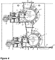
- each recycling unit 1, 1' comprises comprising a first rotor 15 housed in a first stator 2.
- the stator 2 has a substantially cylindrical geometry that facilitates its manufacture.
- the input 16 and the output 17 are situated along the same vertical axis 18 which is offset with respect to the central vertical axis 19 of the rotor 15. This offset has the effect of creating, by the rotation of the rotor 15, a suction effect on the pieces of the third ground batch introduced into the input 16. It is also possible to offset the input 16 and the output 17 with respect to one another within the scope of the present invention.
- the stator 2 is provided with a chamber 20 delimited by an external wall of the first rotor 15.
- the chamber 20 is a micronization chamber 20 formed by a recess arranged between two counter-elements 21, 21' mounted on the stator 2 which is substantially cylindrical and comprises an adjustment means 24 organized to adjust the volume and/or shape of the chamber.
- a good compromise shall be found between a good level of grinding of the fibers and an acceptable flowrate. If the distance between the rotor and the counter-element 21, 21' is too low, the recycled product present a too small particle size of the fibers spread in the melted product (i.e. from reinforcement layer if present) and the flowrate of the recycling unit is too low. If the distance between the rotor and the counter-element 21, 21' is too high, the recycled product contain long fibers but present a high flowrate in the exit.
- the micronization chamber 20 allows the mass of the third ground batch introduced into the input opening 16 to accumulate there temporarily. Since the chamber 20 is delimited by the external wall of the rotor 15, the bituminous mass, which is situated in this chamber, will be driven rotationally by the rotation of the rotor 15 and thus swirl around in the chamber 20. Thus, the introduced cold third ground batch will heat up more quickly and will be triturated more easily. This is because the centrifugal force imposed on the mass by the rotor 15 will make it heat up more quickly.
- the mass thus presents in the chamber 20 will be mixed and/or ground in order to melt it.
- the recycling unit 1 is equipped with heating means, the latter contribute towards heating said mass.
- the passage 22 that extends between the input opening 16 and the micronization chamber 20 is chosen to be sufficiently wide so as to facilitate access to the micronization chamber 20.
- the micronization chamber 20 is mounted in an adjustable and removable manner in the stator 2. To that end, the micronization chamber 20 is mounted between two supports 23, each being provided with an adjustment means 24, for example formed by a screw and a bolt.
- the adjustment means 24 allow not only mounting and removal of the chamber, but also make it possible to vary of the size of the chamber by moving it nearer or further away with respect to the external wall of the rotor 15.
- One end of the counter-element 21, situated downstream of the chamber 20, forms the tip of the blade of a knife which is used to shear the pieces of the third ground batch triturated in the chamber 20 more and to disintegrate the reinforcement if present in the pieces.
- the blade of the knife is also used to shear and pulverize the mineral covering provided on the surface of the bituminous membrane.
- a deflector 25 is mounted downstream of the micronization chamber.
- the deflector 25 is mounted on the stator 2 and disposed in the output opening 21, along part of the external wall of the rotor 11.
- the deflector 25 is preferably trapezoidal in shape and delimits a first cavity 26, formed between the lower part of the support 23, the upper part of the deflector 25, the stator 2 and the rotor 15.
- the bituminous mass that has passed through the chamber 20 can accumulate temporarily in this first cavity 26 which thus forms a buffer. From this buffer, the melted mass will then be conveyed by the deflector 25 along the rotor 15 and will lubricate the latter.
- a scraper 27 is mounted downstream of the deflector 25 also in the output opening 21.
- the scraper 27 and the deflector 25 are disposed so as to be at a distance from each other on opposite sides of the output opening 17. Thus, a corridor is created between the deflector 25 and the scraper 27 through which the processed material can reach the output opening 17.
- the scraper 27 is mounted on a support 28, using adjustment means 29.
- the scraper 27 is used to scrape the external wall of the rotor 15 so as to scrape the bituminous material which accumulates on this wall.
- the scraper 27 extends over at least part of the length of the rotor 15.
- two recycling unit 1 are comprised where the first and second stators 2 and rotors 15 preferably have a substantially identical construction and are placed in series so that the second recycling unit 1' is downstream of the first recycling unit 1.
- an output 17 of the first recycling unit 1 opens into an input 16 of the second recycling unit 1'.
- the identical elements of the second member have been indicated using the same reference as that used for the first.
- the third ground batch is introduced into the input opening 16 of the first recycling unit 1.
- the rotation, indicated by the arrow 30, of the rotor 15 and the offset of the opening 16 with respect to the central axis 19 cause the suction towards the rotor 15 of the introduced third ground batch.
- This will at first accumulate in the opening on the external wall of the rotor which passes through the opening during its rotation. The mass can heat up more quickly if the stator 2 and rotor 15 are heated using a heating body.
- the heated third ground batch will then, by the rotation of the rotor 15, be driven towards the micronization chamber 20 and if applicable towards the first knife blade 21.
- the counter-element 21 and/or the stator 2 are treated with a wear-resistant substance, in particular tungsten carbide.
- the hot mass After having passed the knife blades 21, the hot mass will temporarily accumulate in the cavity 26 in order to heat up more and reach its melting point in order to be next conveyed along the external wall of the rotor 15. The hot mass thus lubricates the rotor 15. Next, the mass reaches the corridor between the deflector 25 and the scraper 27 in order to fall into the output opening 17 under the effect of gravity.
- the scraper 27 takes care of scraping the external wall of the rotor, so as to prevent the mass, which is sticky because of the presence of hot bitumen, accumulating on the rotor 15 and thus preventing its rotation.
- the distance between the scraper 27 and the external wall of the rotor is chosen so that a little bituminous mass remains on the rotor 15 and lubricates its movement.
- the central vertical axis 19 of the rotor 15 of the first recycling unit 1 is aligned with the central vertical axis 19 of the rotor 15 of the second recycling unit 1'.
- the central vertical axis 19 of the rotor 15 of the first recycling unit 1 is offset with the central vertical axis 19 of the rotor 15 of the second recycling unit 1'.
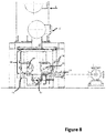
- each recycling unit 1, 1' comprises the same elements as illustrated for the embodiment in figure 1 .
- the stator 2 is provided with a chamber 20 delimited by an external wall of the first rotor 15.
- the chamber 20 is a micronization chamber 20 formed by a recess arranged in a cleat block 31 between two counter-elements 21, 21' mounted on the stator 2.
- a second micronization chamber or cavity 26 is provided delimited by an external wall of the first rotor 15.
- the cavity 26 is formed in a recess arranged in a cleat block 31 between two counter elements 21' and 21".
- the two cleat block are made solidary one to each other and connected to a support element 23 comprising adjustment means 24 organized to adjust the volume and/or shape of the chamber.
- the adjustment means 24 can be operated manually with a wheel 34 (handwheel) or motorized wheel 34.
- the counter elements 21, 21' and 21" are a structural portion of the recycling plant and guide the cleat blocks 31 an 31' when going forward or backward
- the micronization chamber 20 allows the mass of the third ground batch introduced into the input opening 16 to accumulate there temporarily. Since the chamber 20 is delimited by the external wall of the rotor 15, the bituminous mass, which is situated in this chamber, will be driven rotationally by the rotation of the rotor 15 and thus swirl around in the chamber 20.
- a sliding trapdoor 32 can be manually driven by a motor 33.
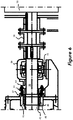
- the rotor 15 is operated by a motor 35 driving a rotation axis 36 connected by a tight connection 37 to the rotor 15.
- the motor 35 is coupled to the rotation axis 36 by a coupling element 38.
- the rotation axis 36 further passes through a roller bearing block 39 disposed between the tight connection 37 and the coupling element 38.
- the tight connection 37 and the roller bearing block 39 are separated by a distance d comprised between 6 and 20 cm, preferably between 7,5 and 15 cm.
- the rotor 15 is on one end connect to a motor 35 driving a rotation axis 36 and on the other end connected to a dead end of said rotation axis 36 by a tight connection 37 to the rotor 15.
- the rotation axis dead end passing through a roller bearing block 46, on the opposite side of the recycling unit 1, 1' with respect to the side connected to the motor 35.
- the roller bearing block 46 is disposed between the tight connection 37 and an end of the rotation axis 36.
- the tight connection 37 and the roller bearing block 39 are separated by a distance e comprised between 6 and 20 cm, preferably between 7,5 and 15 cm.
- the space of a distance d or the space of a distance e allows said melted product overflowing along the driving axis (rotation axis) 36 to be collected in a vessel by flowing through the space provided between the stator and the coupling element provided to couple the rotor of the recycling unit and a motor or on the opposite side between the stator 2 and the end of the driving axis (rotation axis) 36.
- the space of a distance d provided between the tight connection 37 and the roller bearing block 39 allows hot bitumen overflowing from the rotor 15 along the rotation axis 36 to flow downwards, and hereby prevent the roller bearing 40 getting dirt and contaminated by recycled bitumen, which latter would be very detrimental to its lifetime.
- the tight connection 37 comprises an O-ring cord 41 surrounding a metal ring 42 located around said rotation axis 36 and extending over a length of said rotation axis 36 defined between 2 flanges 44, 45.
- At least one the 2 flanges 44, 45 comprises one mobile flange 44 which can move along a direction parallel to the rotation axis 36 in order to reduce or to increase the distance between said 2 flanges 44, 45, for example with a tightening clamp 43.
- a mixing tank 14 is located below the recycling units 1, 1'.
- the mixing tank 14 located below the exit 17 of the recycling unit 1' has a predetermined volume, and comprise at least a first horizontal screw 47 with mixing blades 48, provided to agitate a bitumen product contained in said mixing tank 14.
- the mixing tank comprises heating means to provide a residence temperature comprised between 160 and 200°C, preferably between 170 and 190°C, more preferably around 180°C
- the mixing tank 14 is provided with a first zone 49 and a second zone 50.
- the first zone 49 is located above said second zone 50, being a bottom zone 50.
- the at least first horizontal screw 47 with mixing blades 48 is provided inside said first zone and the number of first horizontal screw can be higher than 1, depending on the size of the horizontal section of the first zone 49. In this preferred illustrated embodiment, the number of horizontal screw 47 with mixing blades 48 is 2.
- the second horizontal screw 51 acts as a conveying means with a baffles 52 and is provided to remove any waste product located in said bottom zone 50.
- the crank 53 allows to open a trapdoor on the side of the recycling unit. By rotating the screw 51, the waste products is evacuated from the mixing tank. This operation is performed after having discharged the mixing tank 14.
- 10 tons of APP waste bituminous membrane product was collected from the production facility.
- the collected waste product was sorted in one single batch.
- the batch was introduced in the plant according to the present invention and was therefore ground 3 times.
- the first grinding step allows to reduce the mean particle size distribution (dso) to 300mm;
- the second grinding step allows to reduce the mean particle size distribution (dso) to 150mm while
- the third grinding step allows to reduce the mean particle size distribution (dso) to 30 mm forming bituminous flakes.
- the batch was melted in the recycling plant at a temperature of about 200°C and form the collected melted material.
- the recycled bitumen was collected in a mixing tank containing 50% of regular bitumen 70/100 as carrier with respect to the volume of the mixing tank. After another 50% of the volume of the mixing tank was filled in with the recycled bitumen, the final recycled bituminous product was obtained after continuous agitation during filling in.
- Example 1 was reproduced except that the particles were depleted in fine particles lower than 6mm.
- Example 1 was reproduced except that the waste bituminous membrane product collected was mainly used and aged APP roofing membrane from demolition site. The collected material was sorted in a single batch.
- Example 3 was reproduced except that the particles were depleted in fine particles lower than 6mm.
- 10 tons of SBS waste bituminous membrane product was collected from the production facility.
- the collected waste product was sorted in one single batch.
- the batch was introduced in the plant according to the present invention and was therefore ground 3 times.
- the first grinding step allows to reduce the mean particle size distribution (dso) to 300mm;
- the second grinding step allows to reduce the mean particle size distribution (dso) to 150mm while
- the third grinding step allows to reduce the mean particle size distribution (dso) to 30 mm forming bituminous flakes.
- the batch was melted in the recycling unit at a temperature of about 200°C and form the collected melted material.
Landscapes
- Chemical & Material Sciences (AREA)
- Engineering & Computer Science (AREA)
- Food Science & Technology (AREA)
- Chemical Kinetics & Catalysis (AREA)
- Organic Chemistry (AREA)
- Civil Engineering (AREA)
- Materials Engineering (AREA)
- Structural Engineering (AREA)
- Polymers & Plastics (AREA)
- Medicinal Chemistry (AREA)
- Health & Medical Sciences (AREA)
- Analytical Chemistry (AREA)
- General Chemical & Material Sciences (AREA)
- Oil, Petroleum & Natural Gas (AREA)
- Environmental & Geological Engineering (AREA)
- Life Sciences & Earth Sciences (AREA)
- Sustainable Development (AREA)
- Processing Of Solid Wastes (AREA)
- Crushing And Pulverization Processes (AREA)
- Separation, Recovery Or Treatment Of Waste Materials Containing Plastics (AREA)
Claims (5)
- Verfahren zum Recyceln eines bituminösen Produkts, vorzugsweise eines bituminösen Membranprodukts, das Verstärkungsschichten enthält, mit den Schritten: :- Sammeln von bituminösen Abfallprodukten, vorzugsweise von bituminösen Membranprodukten, die bituminöse Schichten und Armierungsschichten enthalten, und Sortieren der bituminösen Abfallprodukte in einer Reihe von n Chargen bituminöser Abfallprodukte,- Mindestens ein Mahlschritt jeder Charge der Reihe von n bitumenhaltigen Abfallprodukten oder einer Mischung von n bitumenhaltigen Abfallprodukten, wodurch eine fein gemahlene Charge gebildet wird,- Einführen der fein gemahlenen Charge in eine Recyclingeinheit (1, 1') mit mindestens einem Rotor (15) und einem Stator (2) und einer Mikronisierungskammer (20), wobei die fein gemahlene Charge durch Scherkraft beim Betrieb des Stators, des Rotors und der Mikronisierungskammer (20) erhitzt und geschmolzen wird und ein geschmolzenes Produkt gesammelt wird.- Zuführen des geschmolzenen Produkts in einen Mischtank (14) mit einem vorbestimmten Volumen, der frischen Träger in einem Anteil zwischen 25 und 75 Gew.-%, vorzugsweise zwischen 30 und 60 Gew.-%, bezogen auf das vorbestimmte Volumen, bei einer Verweiltemperatur zwischen 160 und 200°C, vorzugsweise zwischen 170 und 190°C, besonders bevorzugt um 180°C, enthält, wobei der Mischtank (14) kontinuierlich mit einer horizontalen Schnecke (47) mit Mischflügeln (48) gerührt wird, wobei das geschmolzene Produkt in den Mischtank (14) eingespeist wird, bis das Volumen des geschmolzenen Produkts zwischen 25 und 75 %, vorzugsweise zwischen 40 und 70 Gew.-%, in Bezug auf das vorbestimmte Volumen umfasst, um ein recyceltes Bitumen mit einer vordefinierten Viskosität bei 180°C für eine Pumpbarkeit zwischen 500 und 45000 cPS bereitzustellen, wobei der mindestens eine Mahlschritt umfasst:- Erste Zerkleinerung jeder Charge der Serie von n Chargen bituminöser Abfallprodukte in einem Messerzerkleinerer (5) zur Verringerung der Größe jeder Charge in einer ersten zerkleinerten Charge mit einer mittleren Partikelgrößenverteilung zwischen 20 und 50 cm, vorzugsweise zwischen 20 und 40 cm,- Zweite Zerkleinerung jeder ersten geschredderten Charge in einem Rotorgranulator (7), wobei jede erste geschredderte Charge zu einer ersten zerkleinerten Charge mit einer mittleren Partikelgrößenverteilung zwischen 5 und 25 cm, vorzugsweise zwischen 8 und 20 cm, zerkleinert wird,- Eine dritte Zerkleinerung jeder ersten zerkleinerten Charge in einem Rotorgranulator (8, 9), wobei jede erste zerkleinerte Charge zu einer ersten gemahlenen Charge mit einer mittleren Partikelgrößenverteilung zwischen 20 und 50 mm, vorzugsweise zwischen 25 und 40 mm, besonders bevorzugt zwischen 27 und 35 mm, zerkleinert wird.
- Verfahren nach Anspruch 1, bei dem die feingemahlene Charge vor der Zuführung zu der Recycling-Einheit auf einem Vibrationssieb befördert wird, um eine feingemahlene Charge zu sammeln, die im Wesentlichen von Staub und Teilchen mit einer Teilchengröße d100 von weniger als 8 mm, vorzugsweise weniger als 7 mm, besonders bevorzugt weniger als 6 mm, befreit ist.
- Verfahren nach einem der Ansprüche 1 oder 2, wobei die feingemahlene Charge, bevor sie der Recycling-Einheit zugeführt wird, einem Schritt der Trennung von Metallstücken von Nicht-Metallstücken durch Anlegen von Foucault-Strom an die feingemahlene Mischung unterzogen wird und eine feingemahlene Mischung gesammelt wird, die im Wesentlichen von Metallstücken befreit ist.
- Verfahren nach Anspruch 1, bei dem die recycelte Bitumenfraktion durch Pumpen in Chargen entnommen und in einem Schlauchfilter filtriert wird, gegebenenfalls vor oder nach der Lagerung in einem Lagertank.
- Verfahren nach einem der Ansprüche 1 bis 5, wobei die fein gemahlene Mischung bei einer Temperaturzwischen 110°C und 260°C geschmolzen wird.
Priority Applications (2)
| Application Number | Priority Date | Filing Date | Title |
|---|---|---|---|
| PL20811657T PL3852932T3 (pl) | 2019-11-29 | 2020-11-27 | Proces recyklingu odpadów bitumicznych, takich jak odpady bitumiczne w postaci membrany |
| EP21199020.5A EP3967405A1 (de) | 2019-11-29 | 2020-11-27 | Verfahren zur wiederverwertung eines bituminösen abfallprodukts wie z. b. eines abfallprodukts einer bituminösen membran |
Applications Claiming Priority (2)
| Application Number | Priority Date | Filing Date | Title |
|---|---|---|---|
| PCT/EP2019/083184 WO2021104655A1 (en) | 2019-11-29 | 2019-11-29 | Process of recycling a bituminous waste product such as a waste bituminous membrane product |
| PCT/EP2020/083766 WO2021105451A1 (en) | 2019-11-29 | 2020-11-27 | Process of recycling a bituminous waste product such as a waste bituminous membrane product |
Related Child Applications (2)
| Application Number | Title | Priority Date | Filing Date |
|---|---|---|---|
| EP21199020.5A Division-Into EP3967405A1 (de) | 2019-11-29 | 2020-11-27 | Verfahren zur wiederverwertung eines bituminösen abfallprodukts wie z. b. eines abfallprodukts einer bituminösen membran |
| EP21199020.5A Division EP3967405A1 (de) | 2019-11-29 | 2020-11-27 | Verfahren zur wiederverwertung eines bituminösen abfallprodukts wie z. b. eines abfallprodukts einer bituminösen membran |
Publications (2)
| Publication Number | Publication Date |
|---|---|
| EP3852932A1 EP3852932A1 (de) | 2021-07-28 |
| EP3852932B1 true EP3852932B1 (de) | 2022-01-12 |
Family
ID=68806733
Family Applications (2)
| Application Number | Title | Priority Date | Filing Date |
|---|---|---|---|
| EP20811657.4A Active EP3852932B1 (de) | 2019-11-29 | 2020-11-27 | Verfahren zur wiederverwertung eines bituminösen abfallprodukts wie z. b. eines abfallprodukts einer bituminösen membran |
| EP21199020.5A Pending EP3967405A1 (de) | 2019-11-29 | 2020-11-27 | Verfahren zur wiederverwertung eines bituminösen abfallprodukts wie z. b. eines abfallprodukts einer bituminösen membran |
Family Applications After (1)
| Application Number | Title | Priority Date | Filing Date |
|---|---|---|---|
| EP21199020.5A Pending EP3967405A1 (de) | 2019-11-29 | 2020-11-27 | Verfahren zur wiederverwertung eines bituminösen abfallprodukts wie z. b. eines abfallprodukts einer bituminösen membran |
Country Status (10)
| Country | Link |
|---|---|
| US (1) | US12214362B2 (de) |
| EP (2) | EP3852932B1 (de) |
| JP (1) | JP7361211B2 (de) |
| CA (1) | CA3153333A1 (de) |
| DK (1) | DK3852932T3 (de) |
| ES (1) | ES2904976T3 (de) |
| HU (1) | HUE057399T2 (de) |
| PL (1) | PL3852932T3 (de) |
| PT (1) | PT3852932T (de) |
| WO (2) | WO2021104655A1 (de) |
Cited By (1)
| Publication number | Priority date | Publication date | Assignee | Title |
|---|---|---|---|---|
| WO2024056670A1 (en) | 2022-09-14 | 2024-03-21 | Imberbel | Bituminous waterproofing membrane comprising a recycled bituminous binder, a reinforcement and a rejuvenator |
Families Citing this family (1)
| Publication number | Priority date | Publication date | Assignee | Title |
|---|---|---|---|---|
| CN116773572A (zh) * | 2023-06-26 | 2023-09-19 | 浙江师范大学 | 一种扫描电镜试验中新-旧沥青胶浆双层试件成型装置 |
Family Cites Families (10)
| Publication number | Priority date | Publication date | Assignee | Title |
|---|---|---|---|---|
| US4185784A (en) | 1978-07-03 | 1980-01-29 | Eberhard Flita | Heat treatment apparatus for waste containing thermoplastic material |
| US4726846A (en) * | 1986-04-25 | 1988-02-23 | Bird Incorporated | Method of reclaiming waste fiber reinforced asphalt sheet material and reclaimed products of such waste |
| DE4128014A1 (de) * | 1991-08-23 | 1993-02-25 | Ruetgerswerke Ag | Verfahren zur wiederverwendung von reststoffen bituminoeser dichtungsmaterialien |
| BE1015015A3 (fr) | 2002-06-28 | 2004-08-03 | Performance Roof Systems S A E | Procede et unite de recyclage d'une membrane bitumineuse. |
| US7891590B2 (en) * | 2005-11-16 | 2011-02-22 | Tagpap Recycling Aps | Method and apparatus for reusing bituminous products |
| DE102006004148B4 (de) * | 2006-01-27 | 2010-07-29 | Rco Recycling-Centrum Gmbh | Verfahren und Recyclinganlage zur Verwertung bitumenhaltiger Materialien und neuartiges Bitumenmaterial |
| NL1033423C2 (nl) * | 2007-02-19 | 2008-08-20 | Esha Group B V | Inrichting en werkwijze voor het recyclen van bitumineus dakafval. |
| US9574137B2 (en) * | 2013-02-04 | 2017-02-21 | Jan-Niels Pochert | Apparatus and method for recycling bituminous material bodies by melting |
| JP6497899B2 (ja) * | 2014-11-20 | 2019-04-10 | 竹内工業株式會社 | アスファルト材溶解装置 |
| WO2021104652A1 (en) * | 2019-11-29 | 2021-06-03 | Imperbel | Process for recycling a bituminous waste product such as a bituminous waste membrane product |
-
2019
- 2019-11-29 WO PCT/EP2019/083184 patent/WO2021104655A1/en not_active Ceased
-
2020
- 2020-11-27 HU HUE20811657A patent/HUE057399T2/hu unknown
- 2020-11-27 ES ES20811657T patent/ES2904976T3/es active Active
- 2020-11-27 US US17/776,077 patent/US12214362B2/en active Active
- 2020-11-27 EP EP20811657.4A patent/EP3852932B1/de active Active
- 2020-11-27 EP EP21199020.5A patent/EP3967405A1/de active Pending
- 2020-11-27 DK DK20811657.4T patent/DK3852932T3/da active
- 2020-11-27 WO PCT/EP2020/083766 patent/WO2021105451A1/en not_active Ceased
- 2020-11-27 PT PT208116574T patent/PT3852932T/pt unknown
- 2020-11-27 JP JP2022521756A patent/JP7361211B2/ja active Active
- 2020-11-27 CA CA3153333A patent/CA3153333A1/en active Pending
- 2020-11-27 PL PL20811657T patent/PL3852932T3/pl unknown
Cited By (1)
| Publication number | Priority date | Publication date | Assignee | Title |
|---|---|---|---|---|
| WO2024056670A1 (en) | 2022-09-14 | 2024-03-21 | Imberbel | Bituminous waterproofing membrane comprising a recycled bituminous binder, a reinforcement and a rejuvenator |
Also Published As
| Publication number | Publication date |
|---|---|
| US20220388010A1 (en) | 2022-12-08 |
| EP3967405A1 (de) | 2022-03-16 |
| JP7361211B2 (ja) | 2023-10-13 |
| PT3852932T (pt) | 2022-01-27 |
| JP2022553515A (ja) | 2022-12-23 |
| ES2904976T3 (es) | 2022-04-06 |
| US12214362B2 (en) | 2025-02-04 |
| DK3852932T3 (da) | 2022-02-07 |
| HUE057399T2 (hu) | 2022-05-28 |
| WO2021104655A1 (en) | 2021-06-03 |
| PL3852932T3 (pl) | 2022-03-07 |
| EP3852932A1 (de) | 2021-07-28 |
| CA3153333A1 (en) | 2021-06-03 |
| WO2021105451A1 (en) | 2021-06-03 |
Similar Documents
| Publication | Publication Date | Title |
|---|---|---|
| EP3853306B1 (de) | Verfahren zur wiederverwertung eines bituminösen abfallprodukts wie z. b. eines bituminösen abfallmembranprodukts | |
| EP3852932B1 (de) | Verfahren zur wiederverwertung eines bituminösen abfallprodukts wie z. b. eines abfallprodukts einer bituminösen membran | |
| CA3078989A1 (en) | Methods for reclaiming or recycling asphalt and asphalt and asphalt components produced thereby | |
| EP2707458B1 (de) | Geschlossenes koksaufschlämmungssystem und verfahren zur gewinnung von vermakrtungsfähigen koksstücken aus verfestigtem petrolkoks in einer kokstrommel | |
| US7159804B2 (en) | Unit and method for recycling a bituminous membrane | |
| US20230150172A1 (en) | Installation and method for treating composite materials based on thermoplastic materials | |
| JP2008208606A (ja) | 再生骨材製造方法および再生ポーラスアスファルト混合物製造方法 | |
| US20240247124A1 (en) | Method, process and system for recycling an asphalt-based roofing material | |
| KR101816302B1 (ko) | 골재의 파쇄 및 입자별 수집이 가능한 파쇄시스템. | |
| EP0531622B1 (de) | Verfahren zur Wiederverwendung von Reststoffen bituminöser Dichtungsmaterialien | |
| DE102017130315B4 (de) | Granulatbehandlungsvorrichtung und Verfahren zum Betreiben einer Granulatbehandlungsvorrichtung | |
| KR101808854B1 (ko) | 골재의 파쇄 및 입자별 수집이 가능한 파쇄기. | |
| DE19635941C2 (de) | Recyclat auf Basis thermisch aufbereiteter, kunstharzgebundener Schleifkörperreste bzw. -abfälle, Verfahren zu dessen Herstellung und Verwendung dieses Recyclates | |
| CN205700890U (zh) | 一种旧木料粉碎系统 | |
| US12391883B1 (en) | Method, process and system for recycling an asphalt-based roofing material | |
| CN115787399B (zh) | 一种沥青路面回收料精细分离再生系统及分离方法 | |
| US20260042242A1 (en) | System and method for recycling asphalt shingles |
Legal Events
| Date | Code | Title | Description |
|---|---|---|---|
| STAA | Information on the status of an ep patent application or granted ep patent |
Free format text: STATUS: UNKNOWN |
|
| STAA | Information on the status of an ep patent application or granted ep patent |
Free format text: STATUS: THE INTERNATIONAL PUBLICATION HAS BEEN MADE |
|
| PUAI | Public reference made under article 153(3) epc to a published international application that has entered the european phase |
Free format text: ORIGINAL CODE: 0009012 |
|
| STAA | Information on the status of an ep patent application or granted ep patent |
Free format text: STATUS: REQUEST FOR EXAMINATION WAS MADE |
|
| 17P | Request for examination filed |
Effective date: 20210305 |
|
| AK | Designated contracting states |
Kind code of ref document: A1 Designated state(s): AL AT BE BG CH CY CZ DE DK EE ES FI FR GB GR HR HU IE IS IT LI LT LU LV MC MK MT NL NO PL PT RO RS SE SI SK SM TR |
|
| STAA | Information on the status of an ep patent application or granted ep patent |
Free format text: STATUS: EXAMINATION IS IN PROGRESS |
|
| 17Q | First examination report despatched |
Effective date: 20210902 |
|
| GRAP | Despatch of communication of intention to grant a patent |
Free format text: ORIGINAL CODE: EPIDOSNIGR1 |
|
| STAA | Information on the status of an ep patent application or granted ep patent |
Free format text: STATUS: GRANT OF PATENT IS INTENDED |
|
| GRAS | Grant fee paid |
Free format text: ORIGINAL CODE: EPIDOSNIGR3 |
|
| GRAA | (expected) grant |
Free format text: ORIGINAL CODE: 0009210 |
|
| STAA | Information on the status of an ep patent application or granted ep patent |
Free format text: STATUS: THE PATENT HAS BEEN GRANTED |
|
| DAV | Request for validation of the european patent (deleted) | ||
| DAX | Request for extension of the european patent (deleted) | ||
| INTG | Intention to grant announced |
Effective date: 20211202 |
|
| AK | Designated contracting states |
Kind code of ref document: B1 Designated state(s): AL AT BE BG CH CY CZ DE DK EE ES FI FR GB GR HR HU IE IS IT LI LT LU LV MC MK MT NL NO PL PT RO RS SE SI SK SM TR |
|
| REG | Reference to a national code |
Ref country code: GB Ref legal event code: FG4D |
|
| REG | Reference to a national code |
Ref country code: CH Ref legal event code: EP |
|
| REG | Reference to a national code |
Ref country code: PT Ref legal event code: SC4A Ref document number: 3852932 Country of ref document: PT Date of ref document: 20220127 Kind code of ref document: T Free format text: AVAILABILITY OF NATIONAL TRANSLATION Effective date: 20220121 Ref country code: DE Ref legal event code: R096 Ref document number: 602020001625 Country of ref document: DE |
|
| REG | Reference to a national code |
Ref country code: IE Ref legal event code: FG4D |
|
| REG | Reference to a national code |
Ref country code: DK Ref legal event code: T3 Effective date: 20220202 |
|
| REG | Reference to a national code |
Ref country code: FI Ref legal event code: FGE |
|
| REG | Reference to a national code |
Ref country code: AT Ref legal event code: REF Ref document number: 1462012 Country of ref document: AT Kind code of ref document: T Effective date: 20220215 |
|
| REG | Reference to a national code |
Ref country code: NL Ref legal event code: FP |
|
| REG | Reference to a national code |
Ref country code: SE Ref legal event code: TRGR |
|
| REG | Reference to a national code |
Ref country code: NO Ref legal event code: T2 Effective date: 20220112 |
|
| REG | Reference to a national code |
Ref country code: ES Ref legal event code: FG2A Ref document number: 2904976 Country of ref document: ES Kind code of ref document: T3 Effective date: 20220406 |
|
| REG | Reference to a national code |
Ref country code: LT Ref legal event code: MG9D |
|
| REG | Reference to a national code |
Ref country code: SK Ref legal event code: T3 Ref document number: E 39221 Country of ref document: SK |
|
| REG | Reference to a national code |
Ref country code: HU Ref legal event code: AG4A Ref document number: E057399 Country of ref document: HU |
|
| PG25 | Lapsed in a contracting state [announced via postgrant information from national office to epo] |
Ref country code: RS Free format text: LAPSE BECAUSE OF FAILURE TO SUBMIT A TRANSLATION OF THE DESCRIPTION OR TO PAY THE FEE WITHIN THE PRESCRIBED TIME-LIMIT Effective date: 20220112 Ref country code: LT Free format text: LAPSE BECAUSE OF FAILURE TO SUBMIT A TRANSLATION OF THE DESCRIPTION OR TO PAY THE FEE WITHIN THE PRESCRIBED TIME-LIMIT Effective date: 20220112 Ref country code: HR Free format text: LAPSE BECAUSE OF FAILURE TO SUBMIT A TRANSLATION OF THE DESCRIPTION OR TO PAY THE FEE WITHIN THE PRESCRIBED TIME-LIMIT Effective date: 20220112 Ref country code: BG Free format text: LAPSE BECAUSE OF FAILURE TO SUBMIT A TRANSLATION OF THE DESCRIPTION OR TO PAY THE FEE WITHIN THE PRESCRIBED TIME-LIMIT Effective date: 20220412 |
|
| PG25 | Lapsed in a contracting state [announced via postgrant information from national office to epo] |
Ref country code: LV Free format text: LAPSE BECAUSE OF FAILURE TO SUBMIT A TRANSLATION OF THE DESCRIPTION OR TO PAY THE FEE WITHIN THE PRESCRIBED TIME-LIMIT Effective date: 20220112 Ref country code: GR Free format text: LAPSE BECAUSE OF FAILURE TO SUBMIT A TRANSLATION OF THE DESCRIPTION OR TO PAY THE FEE WITHIN THE PRESCRIBED TIME-LIMIT Effective date: 20220413 |
|
| PG25 | Lapsed in a contracting state [announced via postgrant information from national office to epo] |
Ref country code: IS Free format text: LAPSE BECAUSE OF FAILURE TO SUBMIT A TRANSLATION OF THE DESCRIPTION OR TO PAY THE FEE WITHIN THE PRESCRIBED TIME-LIMIT Effective date: 20220512 |
|
| REG | Reference to a national code |
Ref country code: DE Ref legal event code: R097 Ref document number: 602020001625 Country of ref document: DE |
|
| PG25 | Lapsed in a contracting state [announced via postgrant information from national office to epo] |
Ref country code: SM Free format text: LAPSE BECAUSE OF FAILURE TO SUBMIT A TRANSLATION OF THE DESCRIPTION OR TO PAY THE FEE WITHIN THE PRESCRIBED TIME-LIMIT Effective date: 20220112 Ref country code: RO Free format text: LAPSE BECAUSE OF FAILURE TO SUBMIT A TRANSLATION OF THE DESCRIPTION OR TO PAY THE FEE WITHIN THE PRESCRIBED TIME-LIMIT Effective date: 20220112 Ref country code: EE Free format text: LAPSE BECAUSE OF FAILURE TO SUBMIT A TRANSLATION OF THE DESCRIPTION OR TO PAY THE FEE WITHIN THE PRESCRIBED TIME-LIMIT Effective date: 20220112 |
|
| PLBE | No opposition filed within time limit |
Free format text: ORIGINAL CODE: 0009261 |
|
| STAA | Information on the status of an ep patent application or granted ep patent |
Free format text: STATUS: NO OPPOSITION FILED WITHIN TIME LIMIT |
|
| PG25 | Lapsed in a contracting state [announced via postgrant information from national office to epo] |
Ref country code: AL Free format text: LAPSE BECAUSE OF FAILURE TO SUBMIT A TRANSLATION OF THE DESCRIPTION OR TO PAY THE FEE WITHIN THE PRESCRIBED TIME-LIMIT Effective date: 20220112 |
|
| 26N | No opposition filed |
Effective date: 20221013 |
|
| REG | Reference to a national code |
Ref country code: DE Ref legal event code: R081 Ref document number: 602020001625 Country of ref document: DE Owner name: IMPERBEL, BE Free format text: FORMER OWNER: IMPERBEL, LOT, BE |
|
| REG | Reference to a national code |
Ref country code: NO Ref legal event code: CHAD Owner name: IMPERBEL, BE |
|
| REG | Reference to a national code |
Ref country code: LU Ref legal event code: HC Owner name: IMPERBEL; BE Free format text: FORMER OWNER: IMPERBEL Effective date: 20230309 |
|
| REG | Reference to a national code |
Ref country code: SK Ref legal event code: TC4A Ref document number: E 39221 Country of ref document: SK Owner name: IMPERBEL, BEERSEL, BE Effective date: 20230406 |
|
| REG | Reference to a national code |
Ref country code: HU Ref legal event code: HC9C Owner name: IMPERBEL, BE Free format text: FORMER OWNER(S): IMPERBEL, BE |
|
| PG25 | Lapsed in a contracting state [announced via postgrant information from national office to epo] |
Ref country code: MC Free format text: LAPSE BECAUSE OF FAILURE TO SUBMIT A TRANSLATION OF THE DESCRIPTION OR TO PAY THE FEE WITHIN THE PRESCRIBED TIME-LIMIT Effective date: 20220112 |
|
| P01 | Opt-out of the competence of the unified patent court (upc) registered |
Effective date: 20230626 |
|
| PG25 | Lapsed in a contracting state [announced via postgrant information from national office to epo] |
Ref country code: IE Free format text: LAPSE BECAUSE OF NON-PAYMENT OF DUE FEES Effective date: 20221127 |
|
| REG | Reference to a national code |
Ref country code: BE Ref legal event code: PD Owner name: IMPERBEL; BE Free format text: DETAILS ASSIGNMENT: CHANGE OF OWNER(S), OTHER; FORMER OWNER NAME: IMPERBEL Effective date: 20230314 Ref country code: BE Ref legal event code: HC Owner name: IMPERBEL; BE Free format text: DETAILS ASSIGNMENT: CHANGE OF OWNER(S), CHANGE OF OWNER(S) NAME Effective date: 20230314 |
|
| REG | Reference to a national code |
Ref country code: SK Ref legal event code: TB4A Ref document number: E 39221 Country of ref document: SK Free format text: CORRECTION TO GAZETTE 8/2023 - ZMENY V UDAJOCH O MAJITELOCH EUROPSKYCH PATENTOV #HEADERMARGIN_5376:(73) IMPERBEL, BEERSEL, BE |
|
| PG25 | Lapsed in a contracting state [announced via postgrant information from national office to epo] |
Ref country code: CY Free format text: LAPSE BECAUSE OF FAILURE TO SUBMIT A TRANSLATION OF THE DESCRIPTION OR TO PAY THE FEE WITHIN THE PRESCRIBED TIME-LIMIT Effective date: 20220112 |
|
| PG25 | Lapsed in a contracting state [announced via postgrant information from national office to epo] |
Ref country code: MK Free format text: LAPSE BECAUSE OF FAILURE TO SUBMIT A TRANSLATION OF THE DESCRIPTION OR TO PAY THE FEE WITHIN THE PRESCRIBED TIME-LIMIT Effective date: 20220112 |
|
| PG25 | Lapsed in a contracting state [announced via postgrant information from national office to epo] |
Ref country code: MT Free format text: LAPSE BECAUSE OF FAILURE TO SUBMIT A TRANSLATION OF THE DESCRIPTION OR TO PAY THE FEE WITHIN THE PRESCRIBED TIME-LIMIT Effective date: 20220112 |
|
| PGFP | Annual fee paid to national office [announced via postgrant information from national office to epo] |
Ref country code: FR Payment date: 20250909 Year of fee payment: 6 |
|
| PGFP | Annual fee paid to national office [announced via postgrant information from national office to epo] |
Ref country code: SK Payment date: 20250917 Year of fee payment: 6 |
|
| REG | Reference to a national code |
Ref country code: CH Ref legal event code: U11 Free format text: ST27 STATUS EVENT CODE: U-0-0-U10-U11 (AS PROVIDED BY THE NATIONAL OFFICE) Effective date: 20251201 |
|
| PGFP | Annual fee paid to national office [announced via postgrant information from national office to epo] |
Ref country code: PT Payment date: 20251106 Year of fee payment: 6 |
|
| PGFP | Annual fee paid to national office [announced via postgrant information from national office to epo] |
Ref country code: HU Payment date: 20251121 Year of fee payment: 6 |
|
| PGFP | Annual fee paid to national office [announced via postgrant information from national office to epo] |
Ref country code: NL Payment date: 20251124 Year of fee payment: 6 Ref country code: LU Payment date: 20251124 Year of fee payment: 6 |
|
| PGFP | Annual fee paid to national office [announced via postgrant information from national office to epo] |
Ref country code: DE Payment date: 20250909 Year of fee payment: 6 |
|
| PGFP | Annual fee paid to national office [announced via postgrant information from national office to epo] |
Ref country code: GB Payment date: 20251001 Year of fee payment: 6 |
|
| PGFP | Annual fee paid to national office [announced via postgrant information from national office to epo] |
Ref country code: NO Payment date: 20251023 Year of fee payment: 6 |
|
| PGFP | Annual fee paid to national office [announced via postgrant information from national office to epo] |
Ref country code: AT Payment date: 20250917 Year of fee payment: 6 |
|
| PGFP | Annual fee paid to national office [announced via postgrant information from national office to epo] |
Ref country code: IT Payment date: 20251121 Year of fee payment: 6 Ref country code: FI Payment date: 20251124 Year of fee payment: 6 Ref country code: DK Payment date: 20251023 Year of fee payment: 6 |
|
| PGFP | Annual fee paid to national office [announced via postgrant information from national office to epo] |
Ref country code: TR Payment date: 20251106 Year of fee payment: 6 Ref country code: BE Payment date: 20251124 Year of fee payment: 6 |
|
| PGFP | Annual fee paid to national office [announced via postgrant information from national office to epo] |
Ref country code: SE Payment date: 20251020 Year of fee payment: 6 Ref country code: CH Payment date: 20251201 Year of fee payment: 6 |
|
| PGFP | Annual fee paid to national office [announced via postgrant information from national office to epo] |
Ref country code: CZ Payment date: 20251113 Year of fee payment: 6 |
|
| PGFP | Annual fee paid to national office [announced via postgrant information from national office to epo] |
Ref country code: PL Payment date: 20251107 Year of fee payment: 6 |
|
| PGFP | Annual fee paid to national office [announced via postgrant information from national office to epo] |
Ref country code: ES Payment date: 20251209 Year of fee payment: 6 |
|
| PG25 | Lapsed in a contracting state [announced via postgrant information from national office to epo] |
Ref country code: SI Free format text: LAPSE BECAUSE OF FAILURE TO SUBMIT A TRANSLATION OF THE DESCRIPTION OR TO PAY THE FEE WITHIN THE PRESCRIBED TIME-LIMIT Effective date: 20220112 |