EP3852592B1 - Cleaning head for a surface treatment apparatus having one or more stabilizers and surface treatment apparatus having the same - Google Patents
Cleaning head for a surface treatment apparatus having one or more stabilizers and surface treatment apparatus having the same Download PDFInfo
- Publication number
- EP3852592B1 EP3852592B1 EP19863315.8A EP19863315A EP3852592B1 EP 3852592 B1 EP3852592 B1 EP 3852592B1 EP 19863315 A EP19863315 A EP 19863315A EP 3852592 B1 EP3852592 B1 EP 3852592B1
- Authority
- EP
- European Patent Office
- Prior art keywords
- stabilizer
- cleaning head
- surface cleaning
- neck
- main body
- Prior art date
- Legal status (The legal status is an assumption and is not a legal conclusion. Google has not performed a legal analysis and makes no representation as to the accuracy of the status listed.)
- Active
Links
Images






Classifications
-
- A—HUMAN NECESSITIES
- A47—FURNITURE; DOMESTIC ARTICLES OR APPLIANCES; COFFEE MILLS; SPICE MILLS; SUCTION CLEANERS IN GENERAL
- A47L—DOMESTIC WASHING OR CLEANING; SUCTION CLEANERS IN GENERAL
- A47L9/00—Details or accessories of suction cleaners, e.g. mechanical means for controlling the suction or for effecting pulsating action; Storing devices specially adapted to suction cleaners or parts thereof; Carrying-vehicles specially adapted for suction cleaners
- A47L9/02—Nozzles
- A47L9/04—Nozzles with driven brushes or agitators
- A47L9/0455—Bearing means therefor
-
- A—HUMAN NECESSITIES
- A47—FURNITURE; DOMESTIC ARTICLES OR APPLIANCES; COFFEE MILLS; SPICE MILLS; SUCTION CLEANERS IN GENERAL
- A47L—DOMESTIC WASHING OR CLEANING; SUCTION CLEANERS IN GENERAL
- A47L5/00—Structural features of suction cleaners
- A47L5/12—Structural features of suction cleaners with power-driven air-pumps or air-compressors, e.g. driven by motor vehicle engine vacuum
- A47L5/22—Structural features of suction cleaners with power-driven air-pumps or air-compressors, e.g. driven by motor vehicle engine vacuum with rotary fans
- A47L5/28—Suction cleaners with handles and nozzles fixed on the casings, e.g. wheeled suction cleaners with steering handle
-
- A—HUMAN NECESSITIES
- A47—FURNITURE; DOMESTIC ARTICLES OR APPLIANCES; COFFEE MILLS; SPICE MILLS; SUCTION CLEANERS IN GENERAL
- A47L—DOMESTIC WASHING OR CLEANING; SUCTION CLEANERS IN GENERAL
- A47L9/00—Details or accessories of suction cleaners, e.g. mechanical means for controlling the suction or for effecting pulsating action; Storing devices specially adapted to suction cleaners or parts thereof; Carrying-vehicles specially adapted for suction cleaners
- A47L9/0009—Storing devices ; Supports, stands or holders
- A47L9/0054—Stands or the like for temporary interruption of work
-
- A—HUMAN NECESSITIES
- A47—FURNITURE; DOMESTIC ARTICLES OR APPLIANCES; COFFEE MILLS; SPICE MILLS; SUCTION CLEANERS IN GENERAL
- A47L—DOMESTIC WASHING OR CLEANING; SUCTION CLEANERS IN GENERAL
- A47L9/00—Details or accessories of suction cleaners, e.g. mechanical means for controlling the suction or for effecting pulsating action; Storing devices specially adapted to suction cleaners or parts thereof; Carrying-vehicles specially adapted for suction cleaners
- A47L9/009—Carrying-vehicles; Arrangements of trollies or wheels; Means for avoiding mechanical obstacles
Definitions
- the present invention is generally directed to surface treatment apparatuses and more specifically to a cleaning head for a surface treatment apparatus having one or more stabilizers.
- Surface treatment apparatuses may include vacuum cleaners configured to suction debris from a surface (e.g., a floor).
- the vacuum cleaner may include a surface cleaning head having one or more brush rolls configured to agitate a surface (e.g., a carpet) to urge debris into an airflow generated by the vacuum cleaner. The debris within the airflow may then be deposited in a debris collector for later disposal.
- US 8,429,791 B2 disclosed an upright surface treating appliance including a main body and a stand pivotable relative to the main body between a supporting position and a retracted position.
- a stand retaining mechanism for releasably retaining the stand in the supporting position, and which includes a locking member pivotably moveable about a first axis to release the stand as it is moved from the supporting position to the retracted position, and about a second axis spaced from the first axis to retain the stand as it is returned to the supporting position.
- US 2015/0067981 A1 discloses an upright vacuum cleaner having a nozzle and a support moveable between a projected state and a retracted state. The support, in its projected state, is adapted to support the vacuum cleaner in a self-standing position. The support is mounted to the nozzle and projects from the nozzle in its projected state.
- JP 2003102663 A discloses a floor surface washing cleaner in which an auxiliary plate is fitted to a brush case fitted with an operation handle rotatable with respect to the floor surface and an extensible damper is fitted between the operation handle and the auxiliary plate.
- US 2010/0088842 A1 discloses a surface treating appliance including a device generating a flow of fluid in the form of a motor and a fan, housed in a main body.
- a hose and wand assembly, a surface treating head and a rotary change over valve are also provided. The valve is selectively rotatable to allow fluid flow from either the surface-treating head or the hose.
- a support assembly is moveable between a supporting position in which it supports the main body and a retracted position.
- US 2009/064450 A1 discloses a surface-treating appliance including a main body, a surface-treating head and a stand.
- the stand is located on a rear portion of the appliance and is moveable between a supporting position in which is supports the main body in an upright position and a stored position.
- the stand is moveable between the supporting and stored positions in response to movement of the main body between its upright position and an inclined position.
- the present disclosure is generally directed to a surface treatment apparatus having an upright portion and a surface cleaning head pivotally coupled to the upright portion.
- the upright portion is transitionable between an in-use position and a storage position by pivoting the upright portion relative to the surface cleaning head.
- the surface cleaning head includes at least one stabilizer configured to transition from an extended position to a retracted position in response to, for example, transitioning the upright portion between the storage position and the in-use position.
- the stabilizer may improve the stability of the surface treatment apparatus when, for example, the surface treatment apparatus is not in-use without substantially interfering with the usage of the surface treatment apparatus. This may prevent the surface treatment apparatus from inadvertently tipping over and causing damage to, for example, itself, other objects, an animal, and/or a person.
- FIG. 1 shows a schematic view of a vacuum cleaner 100 including a surface cleaning head 102 having one or more wheels 103 rotatably coupled thereto, an upright section 104, a dust cup 106, and a suction motor 108.
- the suction motor 108 is configured generate an airflow into an inlet 110 of the surface cleaning head 102 such that debris can be suctioned from a surface to be cleaned (e.g., a floor). At least a portion of debris that is entrained within the airflow is deposited in the dust cup 106 for later disposal by a user of the vacuum cleaner 100. After passing through the dust cup 106, the airflow is exhausted from the suction motor 108 at an exhaust outlet 112.
- the suction motor 108 can be powered by, for example, one or more batteries and/or an electrical grid.
- the upright section 104 is in a storage (or upright) position.
- the upright section 104 is pivotally coupled to a main body 101 of the surface cleaning head 102 such that the upright section 104 can be pivoted to an in-use (or reclined) position (e.g., as shown FIG. 2 ).
- An axis about which the upright section 104 pivots when transitioning between the storage and in-use positions can extend substantially parallel to an axis about which the one or more wheels 103 rotate.
- One or more stabilizers 114 can be provided that are configured to transition between an extended (e.g., as shown in FIG. 1 ) and retracted (e.g., as shown in FIG. 2 ) position in response to, for example, the upright section 104 transitioning between the storage and in-use positions and/or in response to a user interaction.
- the stabilizer 114 can be configured to extend from the vacuum cleaner 100 and engage (e.g., contact) a surface (e.g., a floor) when the upright section 104 is in the storage position. Such a configuration may improve the stability of the vacuum cleaner 100 when compared to a vacuum cleaner 100 that does not include the stabilizer 114.
- the stabilizer 114 can move towards the retracted position for at least a portion of the pivotal movement such that the stabilizer 114 does not substantially interfere with the use of the vacuum cleaner 100.
- the surface cleaning head 102 can be moved across a surface to be cleaned (e.g., a floor) without the stabilizer 114 engaging (e.g., contacting) the surface to be cleaned.
- the stability of the vacuum cleaner 100 can be improved without substantially interfering with the maneuverability of the vacuum cleaner 100.
- FIG. 3 shows a perspective view of a surface cleaning head 300, which may be an example of the surface cleaning head 102 of FIG. 1 .
- the surface cleaning head 300 includes a neck 302 pivotally coupled to a main body 303 of the surface cleaning head 300.
- the neck 302 is configured to receive a wand 304 such that the neck 302 and the wand 304 can be described as collectively forming at least a portion of an upright section of a vacuum cleaner such as, for example, the vacuum cleaner 100 of FIG. 1 .
- the surface cleaning head 300 can include one or more main wheels 306 that are configured to rotate about a rotation axis 308 in response to the surface cleaning head 300 being urged across a surface to be cleaned 301 (e.g., a floor).
- the neck 302 can be configured to pivot about one or more axes.
- the neck 302 can be configured to pivot about a first pivot axis 310 that extends substantially parallel to the rotation axis 308 of the one or more wheels 306.
- the neck 302 and the wand 304 can be transitioned between a storage position (e.g., as shown in FIG. 3 ) and an in-use position (e.g., as shown in FIG. 4 ) in response to pivoting about the first pivot axis 310.
- the neck 302 can be configured to pivot side-to-side about a second pivot axis 312 that extends transverse to (e.g., perpendicular to) the rotation axis 308 of the one or more wheels 306.
- a second pivot axis 312 that extends transverse to (e.g., perpendicular to) the rotation axis 308 of the one or more wheels 306.
- the wand 304 can define a fluid channel 314 such that air drawn into the surface cleaning head 300 through an air inlet 316 can pass through the wand 304.
- the wand 304 can be fluidly coupled to the surface cleaning head 300.
- the wand 304 can be removably coupled to the neck 302 such that the wand 304 can be used independently of the surface cleaning head 300 (e.g., the wand 304 may be configured to couple to a surface cleaning accessory).
- the surface cleaning head 300 includes at least one stabilizer 318 configured to transition between an extended position (e.g., as shown in FIG. 3 ) in which the stabilizer 318 engages (e.g., contacts) the surface to be cleaned 301 and a retracted position (e.g., as shown in FIG. 4 ) in which the stabilizer 318 is configured to be disengaged from the surface to be cleaned 301.
- the stabilizer 318 is configured to transition between the extended position and the retracted position in response to the neck 302 being pivoted between the storage position and the in-use position.
- the stabilizer 318 can transition from the extended position to the retracted position.
- the stabilizer 318 should not substantially interfere with the movement of the surface cleaning head 300 across a surface to be cleaned 301 when the neck 302 is in the in-use position.
- the stabilizer 318 can transition from the retracted position to the extended position.
- the stabilizers 318 can improve the stability of the surface cleaning head 300 such that, for example, it is less likely to tip over.
- the stabilizer 318 can include one or more wheels coupled thereto (e.g., the at least one wheel 306 and/or an additional wheel).
- the one or more wheels can be configured to engage (e.g., contact) the surface to be cleaned 301 such that the wheels can rollingly engage the surface to be cleaned 301.
- the stabilizer 318 can be configured to extend or retract for only a portion of the pivotal movement of the neck 302. For example, the stabilizer 318 can begin to extend when the neck 302 is being transitioned towards the storage position and when the neck 302 is within a predetermined number of degrees (e.g., 2°, 5°, 7°, 10°, 15°, and/or any other suitable number of degrees) of the storage position. In other words, the stabilizer 318 can be configured to transition between extended and retracted positions in response to the neck 302 pivoting within a predetermined range.
- a predetermined number of degrees e.g., 2°, 5°, 7°, 10°, 15°, and/or any other suitable number of degrees
- the stabilizer 318 when the stabilizer 318 is in the extended position, the stabilizer 318 extends behind the one or more wheels 306 such that the one or more wheels 306 are disposed between at least a portion of the stabilizer 318 and the air inlet 316 of the surface cleaning head 300. Additionally, or alternatively, when the stabilizer 318 is in the extended position, the wand 304 can be positioned between the main body 303 of the surface cleaning head 300 and a distal most portion of the stabilizer 318 (e.g., a portion of the stabilizer 318 configured to engage the surface to be cleaned 301).
- the stabilizer 318 When the stabilizer 318 is in the retracted position, at least a portion of the stabilizer 318 can transition into a cavity defined within the main body 303 of the surface cleaning head 300 such that the one or more wheels 306 are disposed between the surface to be cleaned 301 and at least a portion of the stabilizer 318.
- a plurality of stabilizers 318 can be provided.
- a longitudinal axis 320 of each stabilizer 318 extends transverse to a forward movement direction 322 of the surface cleaning head 300.
- the longitudinal axes 320 extend transverse to each other.
- a separation distance 324 extending between the stabilizers 318 increases as the stabilizers 318 approach the surface to be cleaned 301 such that the stability of the surface cleaning head 300 may be improved.
- the longitudinal axes 320 can extend parallel to each other and/or the forward movement direction 322.
- the surface cleaning head 500 may include a protrusion 504 (shown in hidden lines) configured to urge the stabilizer 318 between the extended and retracted position.
- the protrusion 504 can extend from the neck 302.
- the protrusion 504 can be configured to rotate in response to transitioning the neck 302 between the storage and in-use positions.
- the protrusion 504 can be coupled to a linkage 600 that is configured to engage (e.g., contact) the stabilizer 318.
- the linkage 600 can be pivotally coupled to the protrusion 504 such that, as the protrusion 504 is rotated in response to the transitioning of the neck 302 between the in-use and storage positions, the linkage 600 urges the stabilizer 318 to transition between the retracted and extended positions.
- the linkage 600 can include a pivot arm 602 and a plunger 604 slidably disposed therein such that, as the linkage 600 pivots, the plunger 604 slides within the pivot arm 602.
- a biasing mechanism e.g., a spring
- a biasing mechanism can be provided to urge the plunger 604 into engagement with the stabilizer 318.
- the stabilizer 318 can include a rib 506 that is configured to retain the stabilizer 318 in the extended position until the neck 302 is transitioned towards the storage position.
- the rib 506 can be configured to engage (e.g., contact) a detent.
- FIGS. 7-9 show multiple views of a surface cleaning head 700, which may be an example of the surface cleaning head 300 of FIG. 3 .
- the stabilizer 318 can include a plurality of teeth 702 configured to engage a corresponding gear such that a rack and pinion is formed.
- the plurality of teeth 702 can be configured to engage a gear that rotates in response to the neck 302 transitioning between a storage and an in-use position.
- FIG. 10 shows an example of a surface cleaning head 1000, which may be an example of the surface cleaning head 102 of FIG. 1 .
- the surface cleaning head 1000 includes a neck 1002 pivotally coupled to a main body 1001 of the surface cleaning head 1000.
- the neck 1002 can be configured to pivot relative to the main body 1001 of the surface cleaning head 1000 about one or more axes.
- the neck 1002 can be configured to pivot between an upright position (e.g., as shown in FIG. 10 ) and an in-use position (e.g., as shown in FIG. 11 ).
- the neck 1002 can also be configured to pivot side-to-side.
- the neck 1002 includes one or more stabilizers 1004 configured to transition between an extended position (e.g., as shown in FIG. 10 ) and a retracted position (e.g., as shown in FIG. 11 ).
- an extended position e.g., as shown in FIG. 10
- a retracted position e.g., as shown in FIG. 11
- the stabilizer 1004 is configured to move towards the main body 1001 of the surface cleaning head 1000.
- a portion of the stabilizer 1004 slides within a slot 1006 formed within the neck 1002, wherein the slot 1006 extends longitudinally along the neck 1002.
- the stabilizer 1004 when transitioning to the retracted position, at least a portion of the stabilizer 1004 moves in a direction of the main body 1001 and at least a portion of the stabilizer moves away from the main body 1001 such that the stabilizer 1004 comes out of engagement with a surface to be cleaned (e.g., a floor).
- a surface to be cleaned e.g., a floor
- a pivot arm 1008 can also be provided to constrain the extension distance of the stabilizer 1004.
- the pivot arm 1008 can be pivotally coupled to the stabilizer 1004 and to the neck 1002 or the main body 1001 of the surface cleaning head 1000. As such, as the stabilizer 1004 slides along the slot 1006, the pivot arm 1008 pivots relative to the stabilizer 1004 and the neck 1002 or the main body 1001.
- the stabilizer 1004 can be configured to extend or retract for only a portion of the pivotal movement of the neck 1002. For example, the stabilizer 1004 can begin to extend when the neck 1002 is being transitioned towards the storage position and when the neck 1002 is within a predetermined number of degrees (e.g., 2°, 5°, 7°, 10°, 15°, and/or any other suitable number of degrees) of the storage position. In other words, the stabilizer 1004 can be configured to transition between extended and retracted positions in response to the neck 1002 pivoting within a predetermined range.
- a predetermined number of degrees e.g., 2°, 5°, 7°, 10°, 15°, and/or any other suitable number of degrees
- FIG. 12 is a perspective view of the surface cleaning head 1000 of FIG. 10 .
- the neck 1002 can include a plurality of stabilizers 1004 configured to extend therefrom.
- a longitudinal axis 1200 of each of the stabilizers 1004 can extend transverse to a forward direction of travel 1202.
- the longitudinal axes 1200 can extend transverse to each other.
- a separation distance 1204 extending between the stabilizers 1004 can increase as the stabilizers 1004 extend in a direction away from the main body 1001 of the surface cleaning head 1000.
- the longitudinal axes 1200 can extend parallel to each other.
- FIG. 13 shows a perspective view of the neck 1002 of FIG. 10 having the stabilizers 1004 in the retracted position and
- FIG. 14 shows a perspective view of the neck 1002 having the stabilizers 1004 in the extended position.
- FIG. 15 shows a side view of the surface cleaning head 1000 having the neck 1002 in an in-use position.
- FIG. 16 shows a perspective view of a surface cleaning head 1600, which may be an example of the surface cleaning head 102 of FIG. 1 .
- the surface cleaning head 1600 includes a neck 1602 pivotally coupled to a main body 1601 of the surface cleaning head 1600.
- the neck 1602 is configured to pivot between a storage and an in-use position. In some instances, the neck 1602 can also be configured to pivot side-to-side.
- One or more stabilizers 1604 are coupled to the neck 1602 and configured to transition between an extended position (e.g., as shown in FIG. 16 ) and a retracted position (e.g., as shown in FIG. 17 ).
- the stabilizers 1604 can be configured to transition from the retracted position to the extended position in response to actuation of a lever 1606.
- the lever 1606 can be configured to be actuated by a user (e.g., in response to a user depressing the lever 1606 using a foot).
- the one or more stabilizers 1604 can be configured to transition from the extended position to the retracted position in response to a subsequent actuation of the lever 1606.
- the stabilizers 1604 can be configured such that a subsequent actuation of the lever 1606 causes a biasing mechanism (e.g., a spring) to urge the stabilizers 1604 towards the retracted position.
- a biasing mechanism e.g., a spring
- the stabilizers 1604 can be configured to transition from the extended position to the retracted position in response to transitioning the neck 1602 from a storage position towards an in-use position.
- a pivot arm 1610 may also be pivotally coupled to the stabilizer 1604 and the neck 1602 or the main body 1601 of the surface cleaning head 1600.
- the pivot arm 1610 limits the distance that the stabilizer 1604 can extend from the main body 1601 of the surface cleaning head 1600.
- a plurality of stabilizers 1604 can be coupled to the neck 1602.
- a longitudinal axis 1612 of each stabilizer 1604 can extend transverse to a forward movement direction 1614 of the surface cleaning head 1600.
- the longitudinal axes 1612 can extend transverse to each other.
- the longitudinal axes 1612 can extend parallel to each other.
- the stabilizers 1604 and lever 1606 may be part of a stabilizer assembly that is removably coupled to the neck 1602. As such, the stabilizer assembly can be installed by a user of the vacuum cleaner.
- FIG. 18 shows a perspective view of a surface cleaning head 1800, which may be an example of the surface cleaning head 102 of FIG. 1 .
- the surface cleaning head 1800 includes a neck 1802 pivotally coupled to a main body 1801 of the surface cleaning head 1800.
- the neck 1802 can be configured to pivot side-to-side and between a storage position (e.g., as shown in FIG. 18 ) and an in-use position (e.g., as shown in FIG. 19 ).
- a stabilizer 1804 is configured to extend from the main body 1801 of the surface cleaning head 1800.
- the stabilizer 1804 can be configured such that it transitions to an extended position (e.g., as shown in FIG. 18 ) when the neck 1802 transitions to the storage position.
- the stabilizer 1804 can include a biasing mechanism that urges the stabilizer 1804 towards the extended position.
- the neck 1802 may cause a latch to be released such that the stabilizer 1804 extends.
- the stabilizer 1804 includes a plurality of telescoping parts 1806, wherein at least one of the telescoping parts 1806 is configured to receive at least one other telescoping part 1806.
- a distal most telescoping part 1806 can include a support 1808 extending therefrom. The support 1808 can extend from the distal most telescoping part 1806 at an angle such that the support 1808 extends substantially parallel to a surface on which the surface cleaning head 1800 rests (e.g., a floor).
- the stabilizer 1804 may transition from the extended position to a retracted position (e.g., as shown in FIG. 19 ) in response to a user exerting a force on the telescoping parts 1806 such that one or more of the telescoping parts 1806 are received within at least one other telescoping part 1806. In some instances, the stabilizer 1804 may be transitioned from the extended position to the retracted position in response to the neck 1802 being transitioned from the in-use position to the storage position.
- FIG. 20 shows a perspective view of the stabilizer 1804 in the extended position
- FIG. 21 shows a perspective view of the stabilizer 1804 in the retracted position.
- the stabilizer 1804 can include a first plurality of telescoping parts 2000 and a second plurality of telescoping parts 2002.
- the first and second plurality of telescoping parts 2000 and 2002 are disposed on opposing sides of the surface cleaning head 1800.
- the neck 1802 and one or more wheels 2004 can be disposed between at least a portion of the first and second plurality of telescoping parts 2000 and 2002.
- the support 1808 can extend between the first and second plurality of telescoping parts 2000 and 2002.
- a user may exert a force on the support 1808 (e.g., using a foot).
- a user may, while causing the neck 1802 to be transitioned into an in-use position, transition the stabilizer 1804 into the retracted position.
- FIG. 22 shows a perspective view of a surface cleaning head 2200, which may be an example of the surface cleaning head 102 of FIG. 1 .
- the surface cleaning head 2200 includes a neck 2202 pivotally coupled to a main body 2204 of the surface cleaning head 2200.
- the neck 2202 can be configured to pivot side-to-side and between a storage position (e.g., as shown in FIG. 22 ) and an in-use position (e.g., as shown in FIG. 23 ).
- the surface cleaning head 2200 can include a stabilizer 2206 configured to transition between an extended position (e.g., as shown in FIG. 22 ) and a retracted position (e.g., as shown in FIG. 23 ).
- the stabilizer 2206 can transition between the extended and retracted positions in response to, for example, the transitioning of the neck 2202 between the storage and in-use positions.
- the stabilizer 2206 can be configured to extend or retract for only a portion of the pivotal movement of the neck 2202. For example, the stabilizer 2206 can begin to extend when the neck 2202 is being transitioned towards the storage position and when the neck 2202 is within a predetermined number of degrees (e.g., 2°, 5°, 7°, 10°, 15°, and/or any other suitable number of degrees) of the storage position. In other words, the stabilizer 2206 can be configured to transition between extended and retracted positions in response to the neck 2202 pivoting within a predetermined range.
- a predetermined number of degrees e.g., 2°, 5°, 7°, 10°, 15°, and/or any other suitable number of degrees
- the stabilizer 2206 can be coupled to one or more wheels 2208. As such, when the stabilizer 2206 transitions between the extended and retracted positions, the stabilizer 2206 urges the one or more wheels 2208 between an extended position (e.g., as shown in FIG. 22 ) and a retracted position (e.g., as shown in FIG. 23 ). When in the retracted position, the one or more wheels 2208 can be used to maneuver the surface cleaning head 2200 over a surface (e.g., a floor) during a cleaning operation.
- a surface e.g., a floor
- the one or more wheels 2208 may improve the stability of the surface cleaning head 2200 when the neck 2202 is in the storage position while still allowing the surface cleaning head 2200 to be maneuvered over the surface using the one or more wheels 2208 (e.g., as shown in FIG. 24 ).
- the stabilizer 2206 can be configured to slideably engage a track 2210 defined in at least a portion of the main body 2204 of the surface cleaning head 2200. Additionally, or alternatively, the track 2210 can be defined in at least a portion of the neck 2202. In some instances, and as shown, the track 2210 can be configured to extend beyond a rearward most portion of the one or more wheels 2208 when the one or more wheels 2208 are in the retracted position. In other words, when in the retracted position, the one or more wheels 2208 can be disposed between the main body 2204 of the surface cleaning head 2200 and a distal most portion of the track 2210. In other instances, the track 2210 may be defined within the main body 2204 such that the track does not extend beyond the one or more wheels 2208 when the one or more wheels 2208 are in the retracted position.
- FIG. 25 shows a schematic view of a surface cleaning head 2500, which may be an example of the surface cleaning head 102 of FIG. 1 .
- the surface cleaning head 2500 includes a plurality of stabilizers 2502 configured to rotate about a rotation axis 2504.
- the rotation axis 2504 may be the axis about which one or more wheels 2506 rotatably coupled to a main body 2508 of the surface cleaning head 2500 rotate.
- the one or more wheels 2506 When in the extended position (e.g., as shown in FIG. 25 ) the one or more wheels 2506 are disposed between at least a portion of the stabilizers 2502 and the main body 2508 of the surface cleaning head 2500.
- the stabilizers 2502 When in the retracted position, the stabilizers 2502 are received within a corresponding receptacle 2510 defined within the main body 2508 of the surface cleaning head 2500.
- the stabilizers 2502 are shown as having an "L” shape, other configurations are possible.
- the stabilizers 2502 may have a "J" shape, a "P” shape, a “T” shape, and/or any other suitable shape.
- the stabilizers 2502 may be substantially straight and may not include a portion that is configured to extend behind the one or more wheels 2506.
- the stabilizers 2502 may be coupled together such that the stabilizers 2502 collectively form a "U" shaped stabilizer.
- the "U" shaped stabilizer maybe configured such that is extends between the wheels 2506 or such that the wheels 2506 are disposed within the area defined within the "U" shaped stabilizer.
- FIGS. 26 and 27 show perspective side views of a surface cleaning head 2600, which may be an example of the surface cleaning head 102 of FIG. 1 .
- the surface cleaning head 2600 includes a main body 2602, a neck 2604 that is pivotally coupled to the main body 2602 and that is configured to receive a wand (e.g., the wand 304 of FIG. 3 ), a plurality of main wheels 2606 (e.g., wheels used to maneuver the surface cleaning head 2600 during use while cleaning) rotatably coupled to the main body 2602, and a plurality of stabilizers 2608 configured to transition between an extended position (e.g., as shown in FIG. 26 ) and a retracted position (e.g., as shown in FIG.
- a wand e.g., the wand 304 of FIG. 3
- main wheels 2606 e.g., wheels used to maneuver the surface cleaning head 2600 during use while cleaning
- stabilizers 2608 configured to transition between an extended position (
- the stabilizers 2608 can each include a respective stabilizer wheel 2610.
- a substantial portion of the stabilizer wheels 2610 e.g., at least 95% of a diameter of the stabilizer wheels 2610 can extend beyond a rearmost surface 2609 of the main body 2602 and, when in the retracted position, the stabilizer wheels 2610 can extend substantially between the rearmost surface 2609 and a forwardmost surface 2611 of the neck 2604 (e.g., a measure of a length of the stabilizer wheel 2610 extending beyond a respective surface measures less than 5% of a diameter of the stabilizer wheels 2610).
- the stabilizers 2608 extend from a respective stabilizer opening 2612 defined in the main body 2602.
- Each stabilizer opening 2612 can be configured to be angled in a direction of a surface to be cleaned 2616 and may be defined in the main body 2602 at a location between a top surface 2614 of the main body 2602 and a respective main wheel 2606. As such, at least a portion of each stabilizer 2608 can extend over at least a portion of a respective main wheel 2606.
- the stabilizer opening 2612 can be defined in the main body 2602 such that at least a portion is disposed on opposing sides of a central longitudinal axis 2613 of the neck 2604.
- the stabilizer wheels 2610 transition into engagement (e.g., contact) with the surface to be cleaned 2616.
- the stabilizer wheels 2610 transition out of engagement (e.g., contact) with the surface to be cleaned 2616.
- the stabilizers 2608 can extend from the main body 2602 at an angle and in a direction of the surface to be cleaned 2616 such that the stabilizer wheels 2610 transition into and out of engagement with the surface to be cleaned 2616.
- the stabilizers 2608 extend outwardly from the main body 2602 along respective extension axes 2802 and 2804.
- the first extension axis 2802 extends transverse to the second extension axis 2804.
- a stabilizer width 2806 increases with increasing distance from the main body 2602.
- a separation distance 2807 extending between the stabilizers 2608 increases with increasing distance from the main body 2602.
- the stabilizer width 2806 extends between outermost surfaces of the stabilizer wheels 2610.
- the stabilizer width 2806 may measure substantially equal to a surface cleaning head width 2808.
- the stabilizer width 2608 may, for example, measure less than the surface cleaning head width 2808.
- FIG. 30 shows an exploded perspective view of a portion of the surface cleaning head 2600, wherein the stabilizers 2608 are in the extended position. As shown, each stabilizer 2608 is configured to be urged between the extended and retracted position in response to the neck 2604 engaging a linkage 3000.
- the linkage 3000 can be pivotally coupled to a portion of the main body 2602 of the surface cleaning head 2600 and the neck 2604 can include a protrusion 3002 configured to engage at least a portion of the linkage 3000. The engagement between the protrusion 3002 and the linkage 3000 causes the linkage 3000 to pivot relative to the main body 2602 in response to pivotal movement of the neck 2604.
- each linkage 3000 is configured to cause a respective stabilizer 2608 to transition between the extended and retracted positions in response to the pivotal movement of the neck 2604.
- the linkage 3000 can be configured to resist pivotal movement when the linkage 3000 is in the first pivot position and/or the second pivot position such that the stabilizers 2608 are maintained in a respective one of the extended or retracted positions.
- the linkage 3000 may be configured to engage and/or form a portion of a mechanical locking mechanism (e.g., a detent, a snap fit, a friction fit, and/or any other mechanical locking mechanism) and, when the stabilizers 2608 are in the retracted position and the linkage 3000 is in the second pivot position, the linkage 3000 may be biased to the second pivot position by a biasing mechanism (e.g., a spring, an elastic material, such as a rubber, and/or any other biasing mechanism).
- a biasing mechanism e.g., a spring, an elastic material, such as a rubber, and/or any other biasing mechanism
- Such a configuration may allow the stabilizers 2608 to be urged into the retracted position by the biasing force exerted on the linkage 3000 by the biasing mechanism.
- the linkage 3000 may be retained in the first and second pivot positions using a mechanical locking mechanism.
- the protrusion 3002 can extend from the neck 2604 and engage a recess 3004 defined in the linkage 3000.
- the recess 3004 can be defined in an outer surface 3006 of a pivot arm 3008 of the linkage 3000.
- the protrusion 3002 engages at least a portion of the recess 3004 such that at least a portion of the linkage 3000 is caused to pivot in a direction opposite that of the neck 2604.
- FIG. 31 shows a perspective view of the linkage 3000 of FIG. 30 .
- the pivot arm 3008 defines a channel 3102 configured to slideably receive a plunger 3104.
- the plunger 3104 slides within the channel 3102.
- the recess 3004 can have a generally arcuate shape. Additionally, or alternatively, at least a portion of the recess 3004 can be tapered.
- the plunger 3104 can define a plunger opening 3106.
- the plunger opening 3106 can be configured to receive a shaft therethrough such that the shaft rotates relative to the plunger opening 3106.
- the plunger 3104 can be pivotally coupled to a respective stabilizer 2608 using a shaft that extends through the stabilizer 2608 and the plunger opening 3106.
- the linkage 3000 can generally be described as being pivotally coupled to the stabilizer 2608.
- the plunger opening 3106 can include a bearing to facilitate rotation of the shaft relative to the plunger opening 3106.
- the pivot arm 3008 can include a pivot arm opening 3108.
- the pivot arm opening 3108 can be configured to receive a shaft therethrough such that the shaft rotates relative to the pivot arm opening 3108.
- the pivot arm 3008 can be coupled to the main body 2602 of the surface cleaning head 2600 using a shaft that extends from the main body 2602 such that the pivot arm 3008 can be pivotally coupled to the main body 2602 of the surface cleaning head 2600.
- the linkage 3000 can generally be described as being pivotally coupled to the main body 2602 and the stabilizer 2608.
- the pivot arm opening 3108 can include a bearing to facilitate rotation of the shaft relative to the pivot arm opening 3108.
- the pivot arm 3008 can also include a rib 3110 that extends proximate to and radially outward from the pivot arm opening 3108. As shown, the rib 3110 extends between a boss 3112 that extends around the pivot arm opening 3108 and the recess 3004. The rib 3110 can be configured to engage one or more detents configured to retain the linkage in the first and/or second pivot positions.
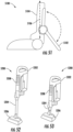
- FIGS. 32 and 33 show a perspective view of the stabilizer 2608 and a linkage 3000 coupled thereto.
- the linkage 3000 is pivotally coupled to the stabilizer 2608.
- the plunger 3104 can be pivotally coupled to the stabilizer 2608.
- an extension distance 3202 of the plunger 3104 may increase as the stabilizer 2608 transitions from the extended position (e.g., as shown in FIG. 32 ) to the retracted position (e.g., as shown in FIG. 33 ).
- FIG. 34 shows a perspective view of the stabilizer 2608.
- the stabilizer 2608 includes a stabilizer body 3400 pivotally coupled to the stabilizer wheel 2610.
- the stabilizer body 3400 includes a longitudinal portion 3402 that extends along a stabilizer longitudinal axis 3404 of the stabilizer 2608 and a wheel coupling portion 3406 that extends in a direction transverse to the stabilizer longitudinal axis 3404.
- the longitudinal portion 3402 can have an arcuate shape, wherein the concave portion of the arc faces the surface to be cleaned 2616.
- the wheel coupling portion 3406 includes a wheel receptacle 3408 configured to receive at least a portion of the stabilizer wheel 2610. As shown, the wheel receptacle 3408 extends at least partially around the stabilizer wheel 2610 and is vertically spaced apart from the longitudinal portion 3402 of the stabilizer body 3400.
- the stabilizer wheel 2610 is rotatably coupled to the wheel receptacle 3408 such that the stabilizer wheel 2610 rotates about a stabilizer wheel rotation axis 3410.
- the wheel receptacle 3408 is configured such that the stabilizer wheel rotation axis 3410 extends transverse to the stabilizer longitudinal axis 3404 at a non-perpendicular angle. Such a configuration may orient the stabilizer wheel 2610 such that the stabilizer wheel rotation axis 3410 is perpendicular to a forward movement direction of the surface cleaning head 2600.
- FIGS. 35 and 36 show a schematic view of a surface cleaning head 3500, which may be an example of the surface cleaning head 102 of FIG. 1 .
- the surface cleaning head 3500 includes a main body 3502, a neck 3504 pivotally coupled to the main body 3502, at least one wheel 3506, and a stabilizer 3508.
- the stabilizer 3508 is pivotally coupled to the main body 3502 of the surface cleaning head 3500 at a first pivot point 3510.
- the at least one wheel 3506 is rotatably coupled to the stabilizer 3508 at a second pivot point 3512.
- the first pivot point 3510 is spaced apart from the second pivot point 3512 such that, as the stabilizer 3508 rotates about the first pivot point 3510, the at least one wheel transitions between an extended position (e.g., as shown in FIG. 35 ) and a retracted position (e.g., as shown in FIG. 36 ) by being rotated around the first pivot point 3510.
- the stabilizer 3508 can be caused to rotate about the first pivot point 3510 in response to, for example, the neck 3504 being transitioned between a storage position (e.g., as shown in FIG. 35 ) and an in-use position (e.g., as shown in FIG. 36 ).
- the at least one wheel 3506 when transitioning between the extended position and the retracted position, can be rotated 180° around the first pivot point 3510 (e.g., in a clockwise or a counter-clockwise direction). Additionally, or alternatively, when transitioning between the extended position and the retracted position the at least one wheel 3506 can be rotated less than or greater than 180° around the first pivot point 3510 (e.g., in a clockwise or a counter-clockwise direction).
- the at least one wheel 3506 can be rotated around the first pivot point 3510 such that a floor facing surface 3514 of the main body 3502 extends transverse to a surface to be cleaned 3516 (e.g., a floor).
- FIGS. 37 and 38 show a perspective view of a surface cleaning head 3700, which may be an example of the surface cleaning head 2200 of FIG. 22 .
- the surface cleaning head 3700 includes a main body 3702, a neck 3704 pivotally coupled to the main body 3702, at least one stabilizer 3706, and at least one wheel 3708 rotatably coupled to the at least one stabilizer 3706.
- the neck 3704 is configured to pivot side-to-side and between a storage position (e.g., as shown in FIG. 37 ) and an in-use position (e.g., as shown in FIG. 38 ).
- the at least one stabilizer 3706 urges the at least one wheel 3708 from an extended position (e.g., as shown in FIG. 37 ) towards a retracted position (e.g., as shown in FIG. 38 ).
- the neck 3704 includes at least one protrusion 3710 configured to engage (e.g., contact) a swivel 3712 pivotally coupled to the main body 3702 of the surface cleaning head 3700.
- the protrusion 3710 is configured to cause the swivel 3712 to pivot in response to the neck 3704 being transitioned between the storage and in-use positions.
- the swivel 3712 is configured to urge the stabilizer 3706 along a track 3714 such that the at least one wheel 3708 is transitioned between the extended and retracted positions in response to the neck 3704 being transitioned between the storage and in-use positions.
- the swivel 3712 can be biased such that the swivel 3712 urges the stabilizer 3706 towards the main body 3702 of the surface cleaning head 3700.
- the swivel can be configured to urge the at least one wheel 3708 towards the retracted position.
- the swivel 3712 can be biased by a spring (e.g., a torsion spring, a compression spring, an extension spring, and/or any other spring).
- the stabilizer 3706 can be coupled to a biasing mechanism (e.g., a spring such as a torsion spring, a compression spring, an extension spring, and/or any other spring).
- a biasing mechanism e.g., a spring such as a torsion spring, a compression spring, an extension spring, and/or any other spring.
- an extension spring 3900 can be coupled to a main body 3902 of a surface cleaning head 3901 and a stabilizer 3906 such that, as the stabilizer 3906 is urged along a track 3914 in a direction away from the main body 3902 of the surface cleaning head 3901, the extension spring 3900 is extended. As the extension spring 3900 extends, the extension spring 3900 exerts a force on the stabilizer 3906 that urges the stabilizer 3906 towards the main body 3902 of the surface cleaning head 3901.
- FIGS. 44 and 45 show a schematic view of a surface cleaning head 4401, which may be an example of the surface cleaning head 102 of FIG. 1 .
- the surface cleaning head 4401 includes a stabilizer 4400 configured to transition between an extended position (e.g., as shown in FIG. 44 ) and a retracted position (e.g., as shown in FIG. 45 ).
- the stabilizer 4400 can include a plurality of links 4402.
- the links 4402 are pivotally coupled to each other such that stabilizer 4400 can transition between the extended position and the retracted position.
- the stabilizer 4400 may generally be referred to as being a scissor mechanism.
- At least one wheel 4404 is coupled to the stabilizer 4400 (e.g., a distal most one of the plurality of links 4402) such that as the stabilizer 4400 is transitioned between the extended and retracted positions, the wheel 4404 is urged between an extended positioned (e.g., as shown in FIG. 44 ) and a retracted position (e.g., as shown in FIG. 45 ).
- FIGS. 46 and 47 show a schematic view of a surface cleaning head 4600, which may be an example of the surface cleaning head 102 of FIG. 1 .
- the surface cleaning head 4600 includes a stabilizer 4602 configured to transition between an extended position (e.g., as shown in FIG. 46 ) and a retracted position (e.g., as shown in FIG. 47 ).
- the stabilizer 4602 includes a lever 4604 configured to pivot about a pivot point 4606 in response to a neck 4608 transitioning between an in-use position (e.g., as shown in FIG. 46 ) and a storage position (e.g., as shown in FIG. 47 ).
- a protrusion 4610 coupled to the neck 4608 engages (e.g., contacts) the lever 4604 such that the lever 4604 is caused to pivot about the pivot point 4606.
- the lever 4604 urges a plunger 4612 along a track 4614.
- the plunger 4612 can be coupled to at least one wheel 4616 such that the plunger 4612 urges the at least one wheel 4616 between an extended position (e.g., as shown in FIG. 46 ) and a retracted position (e.g., as shown in FIG. 47 ).
- FIG. 48 shows a side view of a surface cleaning head 4800, which may be an example of the surface cleaning head 102 of FIG. 1 .
- the surface cleaning head 4800 includes a main body 4802, a neck 4804 pivotally coupled to the main body 4802, and a stabilizer 4806 configured to transition between an extended and retracted position.
- the stabilizer 4806 includes a pivot arm 4808 pivotally coupled to the main body 4802 such that, as the pivot arm 4808 pivots about a pivot point 4810, the pivot arm 4808 urges a plunger 4812 along a track 4814.
- the pivot arm 4808 may be biased (e.g., using a spring) such that the pivot arm urges the plunger 4812 towards the main body 4802 of the surface cleaning head 4800.
- the neck 4804 may include a protrusion 4816 configured to engage (e.g., contact) the pivot arm 4808 such that the plunger 4812 moves along the track 4814 in response to transitioning the neck 4804 between a storage and in-use position.
- at least one wheel 4818 can be coupled to the plunger 4812 such that the at least one wheel 4818 transitions between extended and retracted positions in response to the neck 4804 being transitioned between the storage and in-use positions.
- FIGS. 49 and 50 show a schematic example of a stabilizer 4900, which may be an example of the stabilizer 114 of FIG. 1 , coupled to a portion of a main body 4902 of a surface cleaning head 4904.
- the stabilizer 4900 can include one or more struts 4906 pivotally coupled to the main body 4902 and a wheel 4908.
- the wheel 4908 can be a main wheel of the surface cleaning head 4904.
- the one or more struts 4906 may extend generally parallel to a surface of the main body 4902 of the surface cleaning head 4904 and, when the stabilizer is in the extended position (e.g., as shown in FIG. 50 ), the struts 4906 may extend in a direction away from and behind the main body 4902.
- FIG. 51 shows a schematic example of a surface cleaning head 5100, which may be an example of the surface cleaning head 102 of FIG. 1 .
- the surface cleaning head 5100 includes a stabilizer 5102 pivotally coupled to a neck 5104 of the surface cleaning head 5100.
- the stabilizer 5102 is configured to pivot between an extended and a retracted position (both positions being illustrated in FIG. 51 for purposes of clarity). When in the retracted position, the stabilizer 5102 extends generally parallel to a longitudinal axis 5106 of the neck 5104 and, when in the extended position, the stabilizer 5102 extends in a direction away from the neck 5104 and towards a surface to be cleaned (e.g., a floor).
- the stabilizer 5102 can be configured to be removably coupled to the neck 5104, which may facilitate use of the stabilizer 5102 between multiple surface treatment apparatuses (e.g., vacuum cleaners).
- FIGS. 52 and 53 show a schematic view of an example of a stabilizing system configured to improve the stability of a vacuum cleaner 5200.
- a suction body 5202 e.g., having a suction motor and dust cup
- the vacuum cleaner 5200 is configured to slide along a wand 5204 in a direction of a surface cleaning head 5206 such that a location of a center of mass of the vacuum cleaner can be positioned closer to the surface cleaning head 5206.
- the wand 5204 can be received at least partially within a flexible hose 5208.
- the flexible hose 5208 extends along the suction body 5202.
- An example of a surface cleaning head may include a main body, a neck pivotally coupled to the main body, a stabilizer, and a linkage pivotally coupled to the main body and the stabilizer.
- the linkage may be configured to cause the stabilizer to transition between an extended position and a retracted position in response to a pivotal movement of the neck.
- the neck may include a protrusion configured to engage at least a portion of the linkage.
- the protrusion may be configured to urge the linkage to pivot in response to the pivotal movement of the neck.
- the linkage may include a pivot arm and a plunger.
- the pivot arm may define a channel for receiving the plunger.
- the plunger is configured to slide within the channel in response to the pivotal movement of the neck.
- the stabilizer may include a wheel.
- the surface cleaning head includes a plurality of stabilizers, wherein each stabilizer extends along a respective one of a first axis and a second axis.
- the first axis may extend transverse to the second axis such that a separation distance between the stabilizers increases with increasing distance from the main body.
- the main body may include an opening from which the stabilizer extends.
- the opening may be disposed between a top surface of the main body and a main wheel.
- at least a portion of the stabilizer may extend over at least a portion of the main wheel.
- An example of a vacuum cleaner may include a wand and a surface cleaning head.
- the surface cleaning head may include a main body, a neck, a stabilizer, and a linkage.
- the neck may be configured to receive the wand.
- the neck may be pivotally coupled to the main body such that the wand is configured to transition between a storage position and an in-use position.
- the linkage may be pivotally coupled to the main body and the stabilizer.
- the linkage may be configured to cause the stabilizer to transition between an extended position and a retracted position in response to a pivotal movement of the neck.
- the neck may include a protrusion configured to engage at least a portion of the linkage.
- the protrusion may be configured to urge the linkage to pivot in response to the pivotal movement of the neck.
- the linkage may include a pivot arm and a plunger.
- the pivot arm may define a channel for receiving the plunger.
- the plunger may be configured to slide within the channel in response to the pivotal movement of the neck.
- the stabilizer may include a wheel.
- the surface cleaning head may include a plurality of stabilizers, wherein each stabilizer extends along a respective one of a first axis and a second axis.
- the first axis may extend transverse to the second axis such that a separation distance between the stabilizers increases with increasing distance from the main body.
- the main body may include an opening from which the stabilizer extends.
- the opening may be disposed between a top surface of the main body and a main wheel.
- at least a portion of the stabilizer may extend over at least a portion of the main wheel.
Landscapes
- Engineering & Computer Science (AREA)
- Mechanical Engineering (AREA)
- Nozzles For Electric Vacuum Cleaners (AREA)
- Cleaning Implements For Floors, Carpets, Furniture, Walls, And The Like (AREA)
Description
- The present invention is generally directed to surface treatment apparatuses and more specifically to a cleaning head for a surface treatment apparatus having one or more stabilizers.
- Surface treatment apparatuses may include vacuum cleaners configured to suction debris from a surface (e.g., a floor). The vacuum cleaner may include a surface cleaning head having one or more brush rolls configured to agitate a surface (e.g., a carpet) to urge debris into an airflow generated by the vacuum cleaner. The debris within the airflow may then be deposited in a debris collector for later disposal.
US 8,429,791 B2 disclosed an upright surface treating appliance including a main body and a stand pivotable relative to the main body between a supporting position and a retracted position. A stand retaining mechanism is provided for releasably retaining the stand in the supporting position, and which includes a locking member pivotably moveable about a first axis to release the stand as it is moved from the supporting position to the retracted position, and about a second axis spaced from the first axis to retain the stand as it is returned to the supporting position.
US 2015/0067981 A1 discloses an upright vacuum cleaner having a nozzle and a support moveable between a projected state and a retracted state. The support, in its projected state, is adapted to support the vacuum cleaner in a self-standing position. The support is mounted to the nozzle and projects from the nozzle in its projected state.
JP 2003102663 A
US 2010/0088842 A1 discloses a surface treating appliance including a device generating a flow of fluid in the form of a motor and a fan, housed in a main body. A hose and wand assembly, a surface treating head and a rotary change over valve are also provided. The valve is selectively rotatable to allow fluid flow from either the surface-treating head or the hose. A support assembly is moveable between a supporting position in which it supports the main body and a retracted position. The change over valve and support assembly are arranged so that motion of the support assembly between the supporting and retracted positions induces rotary motion of the change over valve.
US 2009/064450 A1 discloses a surface-treating appliance including a main body, a surface-treating head and a stand. The stand is located on a rear portion of the appliance and is moveable between a supporting position in which is supports the main body in an upright position and a stored position. The stand is moveable between the supporting and stored positions in response to movement of the main body between its upright position and an inclined position. - In accordance with the invention there is provided a surface cleaning head and a vacuum cleaner according to the appended claims.
- These and other features and advantages will be better understood by reading the following detailed description, taken together with the drawings, wherein:
-
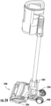
FIG. 1 shows a schematic view of a vacuum cleaner in a storage position. -
FIG. 2 shows a schematic view of the vacuum cleaner ofFIG. 1 in an in-use position. -
FIG. 3 shows a perspective view of a surface cleaning head according to the invention coupled to a wand, wherein the wand is in a storage position. -
FIG. 4 shows a perspective view of the surface cleaning head ofFIG. 3 having the wand in an in-use position. -
FIG. 5 shows a perspective cutaway view of an example embodiment of the surface cleaning head ofFIG. 3 . -
FIG. 6 shows a cross-sectional view of the surface cleaning head ofFIG. 5 , consistent with embodiments of the invention. -
FIG. 7 shows a perspective view of another example of the surface cleaning head ofFIG. 3 , consistent with embodiments of the invention. -
FIG. 8 shows a perspective view of the surface cleaning head ofFIG. 7 , consistent with embodiments of the invention. -
FIG. 9 shows a side view of the surface cleaning head ofFIG. 7 , consistent with embodiments of the invention. -
FIG. 10 shows a side view of a surface cleaning head having a neck in a storage position. -
FIG. 11 shows a side view of the surface cleaning head ofFIG. 10 having the neck in an in-use position. -
FIG. 12 shows a perspective view of the surface cleaning head ofFIG. 10 having the neck in the storage position. -
FIG. 13 shows a perspective view of the neck ofFIG. 10 . -
FIG. 14 shows another perspective view of the neck ofFIG. 10 . -
FIG. 15 shows a side view of the surface cleaning head ofFIG. 10 , wherein the neck is in an in-use position. -
FIG. 16 shows a perspective view of a surface cleaning head. -
FIG. 17 shows another perspective view of the surface cleaning head ofFIG. 16 . -
FIG. 18 shows a side view of a surface cleaning head in a storage position. -
FIG. 19 shows a side view of the surface cleaning head ofFIG. 18 in an in-use position. -
FIG. 20 shows a perspective view of the surface cleaning head ofFIG. 18 . -
FIG. 21 shows another perspective view of the surface cleaning head ofFIG. 18 . -
FIG. 22 shows a perspective view of a surface cleaning head in a storage position. -
FIG. 23 shows a perspective view of the surface cleaning head ofFIG. 22 in an in-use position. -
FIG. 24 shows a perspective view of the surface cleaning head ofFIG. 22 coupled to a suction device. -
FIG. 25 shows a schematic view of a surface cleaning head. -
FIG. 26 shows a perspective view of a surface cleaning head having a plurality of stabilizers in an extended position, consistent with embodiments of the present disclosure. -
FIG. 27 shows a perspective view of the surface cleaning head ofFIG. 26 having the plurality of stabilizers in the retracted position, consistent with embodiments of the present disclosure. -
FIG. 28 shows a top view of the surface cleaning head ofFIG. 26 , consistent with embodiments of the present disclosure. -
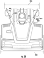
FIG. 29 shows a top view of the surface cleaning head ofFIG. 27 , consistent with embodiments of the present disclosure. -
FIG. 30 shows an exploded perspective view of a portion of the surface cleaning head ofFIG. 26 , consistent with embodiments of the present disclosure. -
FIG. 31 shows a perspective view of a linkage of the surface cleaning head ofFIG. 26 , consistent with embodiments of the present disclosure. -
FIG. 32 shows a perspective view of the linkage ofFIG. 31 in a first pivot position engaging the stabilizer ofFIG. 26 , consistent with embodiments of the present disclosure. -
FIG. 33 shows a perspective view of the linkage ofFIG. 31 in a second pivot position engaging the stabilizer ofFIG. 26 , consistent with embodiments of the present disclosure. -
FIG. 34 shows a perspective view of the stabilizer ofFIG. 26 , consistent with embodiments of the present disclosure. -
FIG. 35 shows a schematic side view of a surface cleaning head having a stabilizer in an extended position. -
FIG. 36 shows a schematic side view of the surface cleaning head ofFIG. 35 having the stabilizer in a retracted position. -
FIG. 37 shows a perspective view of a surface cleaning head having a stabilizer in an extended position. -
FIG. 38 shows a perspective view of the surface cleaning head ofFIG. 37 having the stabilizer in a retracted position. -
FIG. 39 shows a perspective view of a surface cleaning head having a stabilizer in an extended position. -
FIG. 40 shows a perspective view of the surface cleaning head ofFIG. 39 having the stabilizer in a retracted position. -
FIG. 41 shows a perspective view of a portion of a main body of the surface cleaning head ofFIG. 37 . -
FIG. 42 shows another perspective view of a portion of the main body ofFIG. 41 . -
FIG. 43 shows a cross-sectional view of a surface cleaning head. -
FIG. 44 shows a schematic side view of a surface cleaning head having a stabilizer in an extended position. -
FIG. 45 shows a schematic side view of the surface cleaning head ofFIG. 44 having the stabilizer in a retracted position. -
FIG. 46 shows a schematic side view of a surface cleaning head having a stabilizer in an extended position. -
FIG. 47 shows a schematic side view of the surface cleaning head ofFIG. 46 having the stabilizer in a retracted position. -
FIG. 48 shows a side view of a surface cleaning head having a stabilizer in an extended position. -
FIG. 49 shows a schematic perspective view of a stabilizer in a retracted position. -
FIG. 50 shows a schematic perspective view of the stabilizer ofFIG. 49 in an extended position. -
FIG. 51 shows a schematic side view of a surface cleaning head having a stabilizer. -
FIG. 52 shows a schematic perspective view of a vacuum cleaner having a stabilizing system in a first position. -
FIG. 53 shows a schematic perspective view of the vacuum cleaner ofFIG. 52 having the stabilizing system in a second position. - The present disclosure is generally directed to a surface treatment apparatus having an upright portion and a surface cleaning head pivotally coupled to the upright portion. The upright portion is transitionable between an in-use position and a storage position by pivoting the upright portion relative to the surface cleaning head. The surface cleaning head includes at least one stabilizer configured to transition from an extended position to a retracted position in response to, for example, transitioning the upright portion between the storage position and the in-use position. The stabilizer may improve the stability of the surface treatment apparatus when, for example, the surface treatment apparatus is not in-use without substantially interfering with the usage of the surface treatment apparatus. This may prevent the surface treatment apparatus from inadvertently tipping over and causing damage to, for example, itself, other objects, an animal, and/or a person.
-
FIG. 1 shows a schematic view of avacuum cleaner 100 including asurface cleaning head 102 having one ormore wheels 103 rotatably coupled thereto, anupright section 104, adust cup 106, and asuction motor 108. Thesuction motor 108 is configured generate an airflow into aninlet 110 of thesurface cleaning head 102 such that debris can be suctioned from a surface to be cleaned (e.g., a floor). At least a portion of debris that is entrained within the airflow is deposited in thedust cup 106 for later disposal by a user of thevacuum cleaner 100. After passing through thedust cup 106, the airflow is exhausted from thesuction motor 108 at anexhaust outlet 112. Thesuction motor 108 can be powered by, for example, one or more batteries and/or an electrical grid. - As shown in
FIG. 1 , theupright section 104 is in a storage (or upright) position. Theupright section 104 is pivotally coupled to amain body 101 of thesurface cleaning head 102 such that theupright section 104 can be pivoted to an in-use (or reclined) position (e.g., as shownFIG. 2 ). An axis about which theupright section 104 pivots when transitioning between the storage and in-use positions can extend substantially parallel to an axis about which the one ormore wheels 103 rotate. - One or
more stabilizers 114 can be provided that are configured to transition between an extended (e.g., as shown inFIG. 1 ) and retracted (e.g., as shown inFIG. 2 ) position in response to, for example, theupright section 104 transitioning between the storage and in-use positions and/or in response to a user interaction. Thestabilizer 114 can be configured to extend from thevacuum cleaner 100 and engage (e.g., contact) a surface (e.g., a floor) when theupright section 104 is in the storage position. Such a configuration may improve the stability of thevacuum cleaner 100 when compared to avacuum cleaner 100 that does not include thestabilizer 114. - As the
upright section 104 is pivoted towards the in-use position, thestabilizer 114 can move towards the retracted position for at least a portion of the pivotal movement such that thestabilizer 114 does not substantially interfere with the use of thevacuum cleaner 100. As such, thesurface cleaning head 102 can be moved across a surface to be cleaned (e.g., a floor) without thestabilizer 114 engaging (e.g., contacting) the surface to be cleaned. In other words, the stability of thevacuum cleaner 100 can be improved without substantially interfering with the maneuverability of thevacuum cleaner 100. -
FIG. 3 shows a perspective view of asurface cleaning head 300, which may be an example of thesurface cleaning head 102 ofFIG. 1 . As shown, thesurface cleaning head 300 includes aneck 302 pivotally coupled to amain body 303 of thesurface cleaning head 300. Theneck 302 is configured to receive awand 304 such that theneck 302 and thewand 304 can be described as collectively forming at least a portion of an upright section of a vacuum cleaner such as, for example, thevacuum cleaner 100 ofFIG. 1 . As also shown, thesurface cleaning head 300 can include one or moremain wheels 306 that are configured to rotate about arotation axis 308 in response to thesurface cleaning head 300 being urged across a surface to be cleaned 301 (e.g., a floor). - The
neck 302 can be configured to pivot about one or more axes. For example, theneck 302 can be configured to pivot about afirst pivot axis 310 that extends substantially parallel to therotation axis 308 of the one ormore wheels 306. As such, theneck 302 and thewand 304 can be transitioned between a storage position (e.g., as shown inFIG. 3 ) and an in-use position (e.g., as shown inFIG. 4 ) in response to pivoting about thefirst pivot axis 310. Additionally, or alternatively, theneck 302 can be configured to pivot side-to-side about asecond pivot axis 312 that extends transverse to (e.g., perpendicular to) therotation axis 308 of the one ormore wheels 306. Such a configuration may allow thesurface cleaning head 300 to be more easily maneuvered. - The
wand 304 can define afluid channel 314 such that air drawn into thesurface cleaning head 300 through anair inlet 316 can pass through thewand 304. In other words, thewand 304 can be fluidly coupled to thesurface cleaning head 300. In some instances, thewand 304 can be removably coupled to theneck 302 such that thewand 304 can be used independently of the surface cleaning head 300 (e.g., thewand 304 may be configured to couple to a surface cleaning accessory). - As shown, the
surface cleaning head 300 includes at least onestabilizer 318 configured to transition between an extended position (e.g., as shown inFIG. 3 ) in which thestabilizer 318 engages (e.g., contacts) the surface to be cleaned 301 and a retracted position (e.g., as shown inFIG. 4 ) in which thestabilizer 318 is configured to be disengaged from the surface to be cleaned 301. Thestabilizer 318 is configured to transition between the extended position and the retracted position in response to theneck 302 being pivoted between the storage position and the in-use position. - When the
neck 302 is transitioned from the storage position towards the in-use position, thestabilizer 318 can transition from the extended position to the retracted position. As such, thestabilizer 318 should not substantially interfere with the movement of thesurface cleaning head 300 across a surface to be cleaned 301 when theneck 302 is in the in-use position. By way of further example, when theneck 302 is transitioned from the in-use position to the storage position, thestabilizer 318 can transition from the retracted position to the extended position. As such, when theneck 302 is in the storage position, thestabilizers 318 can improve the stability of thesurface cleaning head 300 such that, for example, it is less likely to tip over. - In some instances, the
stabilizer 318 can include one or more wheels coupled thereto (e.g., the at least onewheel 306 and/or an additional wheel). For example, when thestabilizer 318 is in the extended position, the one or more wheels can be configured to engage (e.g., contact) the surface to be cleaned 301 such that the wheels can rollingly engage the surface to be cleaned 301. - In some instances, the
stabilizer 318 can be configured to extend or retract for only a portion of the pivotal movement of theneck 302. For example, thestabilizer 318 can begin to extend when theneck 302 is being transitioned towards the storage position and when theneck 302 is within a predetermined number of degrees (e.g., 2°, 5°, 7°, 10°, 15°, and/or any other suitable number of degrees) of the storage position. In other words, thestabilizer 318 can be configured to transition between extended and retracted positions in response to theneck 302 pivoting within a predetermined range. - As shown, when the
stabilizer 318 is in the extended position, thestabilizer 318 extends behind the one ormore wheels 306 such that the one ormore wheels 306 are disposed between at least a portion of thestabilizer 318 and theair inlet 316 of thesurface cleaning head 300. Additionally, or alternatively, when thestabilizer 318 is in the extended position, thewand 304 can be positioned between themain body 303 of thesurface cleaning head 300 and a distal most portion of the stabilizer 318 (e.g., a portion of thestabilizer 318 configured to engage the surface to be cleaned 301). - When the
stabilizer 318 is in the retracted position, at least a portion of thestabilizer 318 can transition into a cavity defined within themain body 303 of thesurface cleaning head 300 such that the one ormore wheels 306 are disposed between the surface to be cleaned 301 and at least a portion of thestabilizer 318. - As also shown, in some instances, a plurality of
stabilizers 318 can be provided. In these instances, alongitudinal axis 320 of eachstabilizer 318 extends transverse to aforward movement direction 322 of thesurface cleaning head 300. In other words, thelongitudinal axes 320 extend transverse to each other. As a result, aseparation distance 324 extending between thestabilizers 318 increases as thestabilizers 318 approach the surface to be cleaned 301 such that the stability of thesurface cleaning head 300 may be improved. In other instances, thelongitudinal axes 320 can extend parallel to each other and/or theforward movement direction 322. -
FIG. 5 shows a perspective view of an example of asurface cleaning head 500, which may be an example of thesurface cleaning head 300 ofFIG. 3 having a portion of a top cover removed therefrom for purposes of illustration. As shown, amain body 501 of thesurface cleaning head 500 defines acavity 502 for receiving at least a portion of thestabilizer 318. Thestabilizer 318 can be configured to slideably engage thecavity 502 such that, in response to transitioning theneck 302 between the storage position and the in-use position, thestabilizer 318 slides within thecavity 502. - For example, the
surface cleaning head 500 may include a protrusion 504 (shown in hidden lines) configured to urge thestabilizer 318 between the extended and retracted position. For example, theprotrusion 504 can extend from theneck 302. Theprotrusion 504 can be configured to rotate in response to transitioning theneck 302 between the storage and in-use positions. As shown inFIG. 6 , theprotrusion 504 can be coupled to alinkage 600 that is configured to engage (e.g., contact) thestabilizer 318. Thelinkage 600 can be pivotally coupled to theprotrusion 504 such that, as theprotrusion 504 is rotated in response to the transitioning of theneck 302 between the in-use and storage positions, thelinkage 600 urges thestabilizer 318 to transition between the retracted and extended positions. As shown, thelinkage 600 can include apivot arm 602 and aplunger 604 slidably disposed therein such that, as thelinkage 600 pivots, theplunger 604 slides within thepivot arm 602. In some instances, a biasing mechanism (e.g., a spring) can be provided to urge theplunger 604 into engagement with thestabilizer 318. - As also shown in
FIG. 5 , thestabilizer 318 can include arib 506 that is configured to retain thestabilizer 318 in the extended position until theneck 302 is transitioned towards the storage position. For example, therib 506 can be configured to engage (e.g., contact) a detent. -
FIGS. 7-9 show multiple views of asurface cleaning head 700, which may be an example of thesurface cleaning head 300 ofFIG. 3 . As shown, thestabilizer 318 can include a plurality ofteeth 702 configured to engage a corresponding gear such that a rack and pinion is formed. For example, the plurality ofteeth 702 can be configured to engage a gear that rotates in response to theneck 302 transitioning between a storage and an in-use position. -
FIG. 10 shows an example of asurface cleaning head 1000, which may be an example of thesurface cleaning head 102 ofFIG. 1 . As shown, thesurface cleaning head 1000 includes aneck 1002 pivotally coupled to amain body 1001 of thesurface cleaning head 1000. Theneck 1002 can be configured to pivot relative to themain body 1001 of thesurface cleaning head 1000 about one or more axes. For example, theneck 1002 can be configured to pivot between an upright position (e.g., as shown inFIG. 10 ) and an in-use position (e.g., as shown inFIG. 11 ). In some instances, theneck 1002 can also be configured to pivot side-to-side. - As shown, the
neck 1002 includes one ormore stabilizers 1004 configured to transition between an extended position (e.g., as shown inFIG. 10 ) and a retracted position (e.g., as shown inFIG. 11 ). As theneck 1002 is transitioned from the storage position towards the in-use position, at least a portion of thestabilizer 1004 is configured to move towards themain body 1001 of thesurface cleaning head 1000. As thestabilizer 1004 moves towards themain body 1001 of thesurface cleaning head 1000, a portion of thestabilizer 1004 slides within aslot 1006 formed within theneck 1002, wherein theslot 1006 extends longitudinally along theneck 1002. As such, when transitioning to the retracted position, at least a portion of thestabilizer 1004 moves in a direction of themain body 1001 and at least a portion of the stabilizer moves away from themain body 1001 such that thestabilizer 1004 comes out of engagement with a surface to be cleaned (e.g., a floor). - A
pivot arm 1008 can also be provided to constrain the extension distance of thestabilizer 1004. Thepivot arm 1008 can be pivotally coupled to thestabilizer 1004 and to theneck 1002 or themain body 1001 of thesurface cleaning head 1000. As such, as thestabilizer 1004 slides along theslot 1006, thepivot arm 1008 pivots relative to thestabilizer 1004 and theneck 1002 or themain body 1001. - In some instances, the
stabilizer 1004 can be configured to extend or retract for only a portion of the pivotal movement of theneck 1002. For example, thestabilizer 1004 can begin to extend when theneck 1002 is being transitioned towards the storage position and when theneck 1002 is within a predetermined number of degrees (e.g., 2°, 5°, 7°, 10°, 15°, and/or any other suitable number of degrees) of the storage position. In other words, thestabilizer 1004 can be configured to transition between extended and retracted positions in response to theneck 1002 pivoting within a predetermined range. -
FIG. 12 is a perspective view of thesurface cleaning head 1000 ofFIG. 10 . As shown, theneck 1002 can include a plurality ofstabilizers 1004 configured to extend therefrom. As shown, alongitudinal axis 1200 of each of thestabilizers 1004 can extend transverse to a forward direction oftravel 1202. In other words, thelongitudinal axes 1200 can extend transverse to each other. As such, aseparation distance 1204 extending between thestabilizers 1004 can increase as thestabilizers 1004 extend in a direction away from themain body 1001 of thesurface cleaning head 1000. Such a configuration may increase the stability of thesurface cleaning head 1000. In other instances, thelongitudinal axes 1200 can extend parallel to each other. -
FIG. 13 shows a perspective view of theneck 1002 ofFIG. 10 having thestabilizers 1004 in the retracted position andFIG. 14 shows a perspective view of theneck 1002 having thestabilizers 1004 in the extended position.FIG. 15 shows a side view of thesurface cleaning head 1000 having theneck 1002 in an in-use position. -
FIG. 16 shows a perspective view of asurface cleaning head 1600, which may be an example of thesurface cleaning head 102 ofFIG. 1 . As shown, thesurface cleaning head 1600 includes aneck 1602 pivotally coupled to amain body 1601 of thesurface cleaning head 1600. Theneck 1602 is configured to pivot between a storage and an in-use position. In some instances, theneck 1602 can also be configured to pivot side-to-side. - One or
more stabilizers 1604 are coupled to theneck 1602 and configured to transition between an extended position (e.g., as shown inFIG. 16 ) and a retracted position (e.g., as shown inFIG. 17 ). For example, thestabilizers 1604 can be configured to transition from the retracted position to the extended position in response to actuation of alever 1606. Thelever 1606 can be configured to be actuated by a user (e.g., in response to a user depressing thelever 1606 using a foot). By way of further example, the one ormore stabilizers 1604 can be configured to transition from the extended position to the retracted position in response to a subsequent actuation of thelever 1606. For example, thestabilizers 1604 can be configured such that a subsequent actuation of thelever 1606 causes a biasing mechanism (e.g., a spring) to urge thestabilizers 1604 towards the retracted position. By allowing a user to determine when to extend the one ormore stabilizers 1604, it may allow the user to more easily maneuver the vacuum cleaner when, for example, theneck 1602 is in the storage position. Additionally, or alternatively, thestabilizers 1604 can be configured to transition from the extended position to the retracted position in response to transitioning theneck 1602 from a storage position towards an in-use position. - As also shown, when transitioning between the extended and retracted position, the
stabilizer 1604 slides within aslot 1608 formed within theneck 1602. Apivot arm 1610 may also be pivotally coupled to thestabilizer 1604 and theneck 1602 or themain body 1601 of thesurface cleaning head 1600. Thepivot arm 1610 limits the distance that thestabilizer 1604 can extend from themain body 1601 of thesurface cleaning head 1600. - In some instances, and as shown, a plurality of
stabilizers 1604 can be coupled to theneck 1602. Alongitudinal axis 1612 of eachstabilizer 1604 can extend transverse to aforward movement direction 1614 of thesurface cleaning head 1600. In other words, thelongitudinal axes 1612 can extend transverse to each other. In other instances, thelongitudinal axes 1612 can extend parallel to each other. - In some instances, the
stabilizers 1604 andlever 1606 may be part of a stabilizer assembly that is removably coupled to theneck 1602. As such, the stabilizer assembly can be installed by a user of the vacuum cleaner. -
FIG. 18 shows a perspective view of asurface cleaning head 1800, which may be an example of thesurface cleaning head 102 ofFIG. 1 . As shown, thesurface cleaning head 1800 includes aneck 1802 pivotally coupled to amain body 1801 of thesurface cleaning head 1800. Theneck 1802 can be configured to pivot side-to-side and between a storage position (e.g., as shown inFIG. 18 ) and an in-use position (e.g., as shown inFIG. 19 ). - As shown in
FIG. 18 , when theneck 1802 is in the storage position, astabilizer 1804 is configured to extend from themain body 1801 of thesurface cleaning head 1800. Thestabilizer 1804 can be configured such that it transitions to an extended position (e.g., as shown inFIG. 18 ) when theneck 1802 transitions to the storage position. For example, thestabilizer 1804 can include a biasing mechanism that urges thestabilizer 1804 towards the extended position. As such, when theneck 1802 transitions to the storage position, theneck 1802 may cause a latch to be released such that thestabilizer 1804 extends. - As also shown, the
stabilizer 1804 includes a plurality oftelescoping parts 1806, wherein at least one of thetelescoping parts 1806 is configured to receive at least oneother telescoping part 1806. A distalmost telescoping part 1806 can include asupport 1808 extending therefrom. Thesupport 1808 can extend from the distalmost telescoping part 1806 at an angle such that thesupport 1808 extends substantially parallel to a surface on which thesurface cleaning head 1800 rests (e.g., a floor). - The
stabilizer 1804 may transition from the extended position to a retracted position (e.g., as shown inFIG. 19 ) in response to a user exerting a force on thetelescoping parts 1806 such that one or more of thetelescoping parts 1806 are received within at least oneother telescoping part 1806. In some instances, thestabilizer 1804 may be transitioned from the extended position to the retracted position in response to theneck 1802 being transitioned from the in-use position to the storage position. -
FIG. 20 shows a perspective view of thestabilizer 1804 in the extended position andFIG. 21 shows a perspective view of thestabilizer 1804 in the retracted position. As shown, thestabilizer 1804 can include a first plurality oftelescoping parts 2000 and a second plurality oftelescoping parts 2002. The first and second plurality oftelescoping parts surface cleaning head 1800. For example, theneck 1802 and one ormore wheels 2004 can be disposed between at least a portion of the first and second plurality oftelescoping parts - As shown, the
support 1808 can extend between the first and second plurality oftelescoping parts stabilizer 1804 from the extended position to the retracted position, a user may exert a force on the support 1808 (e.g., using a foot). For example, a user may, while causing theneck 1802 to be transitioned into an in-use position, transition thestabilizer 1804 into the retracted position. -
FIG. 22 shows a perspective view of asurface cleaning head 2200, which may be an example of thesurface cleaning head 102 ofFIG. 1 . As shown, thesurface cleaning head 2200 includes aneck 2202 pivotally coupled to amain body 2204 of thesurface cleaning head 2200. Theneck 2202 can be configured to pivot side-to-side and between a storage position (e.g., as shown inFIG. 22 ) and an in-use position (e.g., as shown inFIG. 23 ). - As shown, the
surface cleaning head 2200 can include astabilizer 2206 configured to transition between an extended position (e.g., as shown inFIG. 22 ) and a retracted position (e.g., as shown inFIG. 23 ). Thestabilizer 2206 can transition between the extended and retracted positions in response to, for example, the transitioning of theneck 2202 between the storage and in-use positions. - In some instances, the
stabilizer 2206 can be configured to extend or retract for only a portion of the pivotal movement of theneck 2202. For example, thestabilizer 2206 can begin to extend when theneck 2202 is being transitioned towards the storage position and when theneck 2202 is within a predetermined number of degrees (e.g., 2°, 5°, 7°, 10°, 15°, and/or any other suitable number of degrees) of the storage position. In other words, thestabilizer 2206 can be configured to transition between extended and retracted positions in response to theneck 2202 pivoting within a predetermined range. - The
stabilizer 2206 can be coupled to one ormore wheels 2208. As such, when thestabilizer 2206 transitions between the extended and retracted positions, thestabilizer 2206 urges the one ormore wheels 2208 between an extended position (e.g., as shown inFIG. 22 ) and a retracted position (e.g., as shown inFIG. 23 ). When in the retracted position, the one ormore wheels 2208 can be used to maneuver thesurface cleaning head 2200 over a surface (e.g., a floor) during a cleaning operation. When in the extended position, the one ormore wheels 2208 may improve the stability of thesurface cleaning head 2200 when theneck 2202 is in the storage position while still allowing thesurface cleaning head 2200 to be maneuvered over the surface using the one or more wheels 2208 (e.g., as shown inFIG. 24 ). - As shown, the
stabilizer 2206 can be configured to slideably engage atrack 2210 defined in at least a portion of themain body 2204 of thesurface cleaning head 2200. Additionally, or alternatively, thetrack 2210 can be defined in at least a portion of theneck 2202. In some instances, and as shown, thetrack 2210 can be configured to extend beyond a rearward most portion of the one ormore wheels 2208 when the one ormore wheels 2208 are in the retracted position. In other words, when in the retracted position, the one ormore wheels 2208 can be disposed between themain body 2204 of thesurface cleaning head 2200 and a distal most portion of thetrack 2210. In other instances, thetrack 2210 may be defined within themain body 2204 such that the track does not extend beyond the one ormore wheels 2208 when the one ormore wheels 2208 are in the retracted position. -
FIG. 25 shows a schematic view of asurface cleaning head 2500, which may be an example of thesurface cleaning head 102 ofFIG. 1 . As shown, thesurface cleaning head 2500 includes a plurality ofstabilizers 2502 configured to rotate about arotation axis 2504. In some instances, therotation axis 2504 may be the axis about which one ormore wheels 2506 rotatably coupled to amain body 2508 of thesurface cleaning head 2500 rotate. When in the extended position (e.g., as shown inFIG. 25 ) the one ormore wheels 2506 are disposed between at least a portion of thestabilizers 2502 and themain body 2508 of thesurface cleaning head 2500. When in the retracted position, thestabilizers 2502 are received within a correspondingreceptacle 2510 defined within themain body 2508 of thesurface cleaning head 2500. - While the
stabilizers 2502 are shown as having an "L" shape, other configurations are possible. For example, thestabilizers 2502 may have a "J" shape, a "P" shape, a "T" shape, and/or any other suitable shape. In some instances, thestabilizers 2502 may be substantially straight and may not include a portion that is configured to extend behind the one ormore wheels 2506. - In some instances, the
stabilizers 2502 may be coupled together such that thestabilizers 2502 collectively form a "U" shaped stabilizer. In these instances, the "U" shaped stabilizer maybe configured such that is extends between thewheels 2506 or such that thewheels 2506 are disposed within the area defined within the "U" shaped stabilizer. -
FIGS. 26 and 27 show perspective side views of asurface cleaning head 2600, which may be an example of thesurface cleaning head 102 ofFIG. 1 . As shown, thesurface cleaning head 2600 includes amain body 2602, aneck 2604 that is pivotally coupled to themain body 2602 and that is configured to receive a wand (e.g., thewand 304 ofFIG. 3 ), a plurality of main wheels 2606 (e.g., wheels used to maneuver thesurface cleaning head 2600 during use while cleaning) rotatably coupled to themain body 2602, and a plurality ofstabilizers 2608 configured to transition between an extended position (e.g., as shown inFIG. 26 ) and a retracted position (e.g., as shown inFIG. 27 ). Thestabilizers 2608 can each include arespective stabilizer wheel 2610. When in the extended position, a substantial portion of the stabilizer wheels 2610 (e.g., at least 95% of a diameter of the stabilizer wheels 2610) can extend beyond arearmost surface 2609 of themain body 2602 and, when in the retracted position, thestabilizer wheels 2610 can extend substantially between therearmost surface 2609 and aforwardmost surface 2611 of the neck 2604 (e.g., a measure of a length of thestabilizer wheel 2610 extending beyond a respective surface measures less than 5% of a diameter of the stabilizer wheels 2610). - As shown, the
stabilizers 2608 extend from arespective stabilizer opening 2612 defined in themain body 2602. Eachstabilizer opening 2612 can be configured to be angled in a direction of a surface to be cleaned 2616 and may be defined in themain body 2602 at a location between atop surface 2614 of themain body 2602 and a respectivemain wheel 2606. As such, at least a portion of eachstabilizer 2608 can extend over at least a portion of a respectivemain wheel 2606. In some instances, thestabilizer opening 2612 can be defined in themain body 2602 such that at least a portion is disposed on opposing sides of a centrallongitudinal axis 2613 of theneck 2604. - When the
stabilizers 2608 transition to the extended position, thestabilizer wheels 2610 transition into engagement (e.g., contact) with the surface to be cleaned 2616. When thestabilizers 2608 transition to the retracted position, thestabilizer wheels 2610 transition out of engagement (e.g., contact) with the surface to be cleaned 2616. As such, in some instances, thestabilizers 2608 can extend from themain body 2602 at an angle and in a direction of the surface to be cleaned 2616 such that thestabilizer wheels 2610 transition into and out of engagement with the surface to be cleaned 2616. - As shown in
FIG. 28 , thestabilizers 2608 extend outwardly from themain body 2602 alongrespective extension axes first extension axis 2802 extends transverse to thesecond extension axis 2804. As such, astabilizer width 2806 increases with increasing distance from themain body 2602. In other words, aseparation distance 2807 extending between thestabilizers 2608 increases with increasing distance from themain body 2602. As shown, thestabilizer width 2806 extends between outermost surfaces of thestabilizer wheels 2610. In some instances, for example, when thestabilizers 2608 are in the extended position, thestabilizer width 2806 may measure substantially equal to a surface cleaninghead width 2808. When transitioned to the retracted position, as shown inFIG. 29 , thestabilizer width 2608 may, for example, measure less than the surface cleaninghead width 2808. -
FIG. 30 shows an exploded perspective view of a portion of thesurface cleaning head 2600, wherein thestabilizers 2608 are in the extended position. As shown, eachstabilizer 2608 is configured to be urged between the extended and retracted position in response to theneck 2604 engaging alinkage 3000. Thelinkage 3000 can be pivotally coupled to a portion of themain body 2602 of thesurface cleaning head 2600 and theneck 2604 can include aprotrusion 3002 configured to engage at least a portion of thelinkage 3000. The engagement between theprotrusion 3002 and thelinkage 3000 causes thelinkage 3000 to pivot relative to themain body 2602 in response to pivotal movement of theneck 2604. - As the
linkage 3000 pivots between a first pivot position and a second pivot position, thestabilizer 2608 is caused to transition between the extended and retracted position. In other words, eachlinkage 3000 is configured to cause arespective stabilizer 2608 to transition between the extended and retracted positions in response to the pivotal movement of theneck 2604. As such, thelinkage 3000 can be configured to resist pivotal movement when thelinkage 3000 is in the first pivot position and/or the second pivot position such that thestabilizers 2608 are maintained in a respective one of the extended or retracted positions. For example, when thestabilizers 2608 are in the extended position and the linkage is in the first pivot position, thelinkage 3000 may be configured to engage and/or form a portion of a mechanical locking mechanism (e.g., a detent, a snap fit, a friction fit, and/or any other mechanical locking mechanism) and, when thestabilizers 2608 are in the retracted position and thelinkage 3000 is in the second pivot position, thelinkage 3000 may be biased to the second pivot position by a biasing mechanism (e.g., a spring, an elastic material, such as a rubber, and/or any other biasing mechanism). Such a configuration may allow thestabilizers 2608 to be urged into the retracted position by the biasing force exerted on thelinkage 3000 by the biasing mechanism. By way of further example, thelinkage 3000 may be retained in the first and second pivot positions using a mechanical locking mechanism. - The
protrusion 3002 can extend from theneck 2604 and engage arecess 3004 defined in thelinkage 3000. Therecess 3004 can be defined in an outer surface 3006 of apivot arm 3008 of thelinkage 3000. As theneck 2604 pivots between a storage and in-use position, theprotrusion 3002 engages at least a portion of therecess 3004 such that at least a portion of thelinkage 3000 is caused to pivot in a direction opposite that of theneck 2604. -
FIG. 31 shows a perspective view of thelinkage 3000 ofFIG. 30 . As shown, thepivot arm 3008 defines achannel 3102 configured to slideably receive aplunger 3104. As thelinkage 3000 pivots in response to theneck 2604 transitioning between the storage and in-use positions, theplunger 3104 slides within thechannel 3102. As also shown, therecess 3004 can have a generally arcuate shape. Additionally, or alternatively, at least a portion of therecess 3004 can be tapered. - As shown, the
plunger 3104 can define aplunger opening 3106. Theplunger opening 3106 can be configured to receive a shaft therethrough such that the shaft rotates relative to theplunger opening 3106. For example, theplunger 3104 can be pivotally coupled to arespective stabilizer 2608 using a shaft that extends through thestabilizer 2608 and theplunger opening 3106. As such, thelinkage 3000 can generally be described as being pivotally coupled to thestabilizer 2608. In some instances, theplunger opening 3106 can include a bearing to facilitate rotation of the shaft relative to theplunger opening 3106. - As also shown, the
pivot arm 3008 can include apivot arm opening 3108. Thepivot arm opening 3108 can be configured to receive a shaft therethrough such that the shaft rotates relative to thepivot arm opening 3108. For example, thepivot arm 3008 can be coupled to themain body 2602 of thesurface cleaning head 2600 using a shaft that extends from themain body 2602 such that thepivot arm 3008 can be pivotally coupled to themain body 2602 of thesurface cleaning head 2600. As such, thelinkage 3000 can generally be described as being pivotally coupled to themain body 2602 and thestabilizer 2608. In some instances, thepivot arm opening 3108 can include a bearing to facilitate rotation of the shaft relative to thepivot arm opening 3108. - The
pivot arm 3008 can also include arib 3110 that extends proximate to and radially outward from thepivot arm opening 3108. As shown, therib 3110 extends between aboss 3112 that extends around thepivot arm opening 3108 and therecess 3004. Therib 3110 can be configured to engage one or more detents configured to retain the linkage in the first and/or second pivot positions. -
FIGS. 32 and 33 show a perspective view of thestabilizer 2608 and alinkage 3000 coupled thereto. As shown, thelinkage 3000 is pivotally coupled to thestabilizer 2608. For example, theplunger 3104 can be pivotally coupled to thestabilizer 2608. As also shown, anextension distance 3202 of theplunger 3104 may increase as thestabilizer 2608 transitions from the extended position (e.g., as shown inFIG. 32 ) to the retracted position (e.g., as shown inFIG. 33 ). -
FIG. 34 shows a perspective view of thestabilizer 2608. As shown, thestabilizer 2608 includes astabilizer body 3400 pivotally coupled to thestabilizer wheel 2610. Thestabilizer body 3400 includes alongitudinal portion 3402 that extends along a stabilizerlongitudinal axis 3404 of thestabilizer 2608 and awheel coupling portion 3406 that extends in a direction transverse to the stabilizerlongitudinal axis 3404. In some instances, thelongitudinal portion 3402 can have an arcuate shape, wherein the concave portion of the arc faces the surface to be cleaned 2616. - The
wheel coupling portion 3406 includes awheel receptacle 3408 configured to receive at least a portion of thestabilizer wheel 2610. As shown, thewheel receptacle 3408 extends at least partially around thestabilizer wheel 2610 and is vertically spaced apart from thelongitudinal portion 3402 of thestabilizer body 3400. Thestabilizer wheel 2610 is rotatably coupled to thewheel receptacle 3408 such that thestabilizer wheel 2610 rotates about a stabilizerwheel rotation axis 3410. As shown, thewheel receptacle 3408 is configured such that the stabilizerwheel rotation axis 3410 extends transverse to the stabilizerlongitudinal axis 3404 at a non-perpendicular angle. Such a configuration may orient thestabilizer wheel 2610 such that the stabilizerwheel rotation axis 3410 is perpendicular to a forward movement direction of thesurface cleaning head 2600. -
FIGS. 35 and 36 show a schematic view of asurface cleaning head 3500, which may be an example of thesurface cleaning head 102 ofFIG. 1 . As shown, thesurface cleaning head 3500 includes amain body 3502, aneck 3504 pivotally coupled to themain body 3502, at least onewheel 3506, and astabilizer 3508. - As shown, the
stabilizer 3508 is pivotally coupled to themain body 3502 of thesurface cleaning head 3500 at afirst pivot point 3510. As also shown, the at least onewheel 3506 is rotatably coupled to thestabilizer 3508 at asecond pivot point 3512. Thefirst pivot point 3510 is spaced apart from thesecond pivot point 3512 such that, as thestabilizer 3508 rotates about thefirst pivot point 3510, the at least one wheel transitions between an extended position (e.g., as shown inFIG. 35 ) and a retracted position (e.g., as shown inFIG. 36 ) by being rotated around thefirst pivot point 3510. Thestabilizer 3508 can be caused to rotate about thefirst pivot point 3510 in response to, for example, theneck 3504 being transitioned between a storage position (e.g., as shown inFIG. 35 ) and an in-use position (e.g., as shown inFIG. 36 ). - In some instances, and as shown, when transitioning between the extended position and the retracted position, the at least one
wheel 3506 can be rotated 180° around the first pivot point 3510 (e.g., in a clockwise or a counter-clockwise direction). Additionally, or alternatively, when transitioning between the extended position and the retracted position the at least onewheel 3506 can be rotated less than or greater than 180° around the first pivot point 3510 (e.g., in a clockwise or a counter-clockwise direction). For example, when in the retracted position, the at least onewheel 3506 can be rotated around thefirst pivot point 3510 such that afloor facing surface 3514 of themain body 3502 extends transverse to a surface to be cleaned 3516 (e.g., a floor). -
FIGS. 37 and 38 show a perspective view of asurface cleaning head 3700, which may be an example of thesurface cleaning head 2200 ofFIG. 22 . As shown, thesurface cleaning head 3700 includes amain body 3702, aneck 3704 pivotally coupled to themain body 3702, at least onestabilizer 3706, and at least onewheel 3708 rotatably coupled to the at least onestabilizer 3706. Theneck 3704 is configured to pivot side-to-side and between a storage position (e.g., as shown inFIG. 37 ) and an in-use position (e.g., as shown inFIG. 38 ). When theneck 3704 transitions from the storage position to the in-use position, the at least onestabilizer 3706 urges the at least onewheel 3708 from an extended position (e.g., as shown inFIG. 37 ) towards a retracted position (e.g., as shown inFIG. 38 ). - As shown, the
neck 3704 includes at least oneprotrusion 3710 configured to engage (e.g., contact) aswivel 3712 pivotally coupled to themain body 3702 of thesurface cleaning head 3700. Theprotrusion 3710 is configured to cause theswivel 3712 to pivot in response to theneck 3704 being transitioned between the storage and in-use positions. Theswivel 3712 is configured to urge thestabilizer 3706 along atrack 3714 such that the at least onewheel 3708 is transitioned between the extended and retracted positions in response to theneck 3704 being transitioned between the storage and in-use positions. - The
swivel 3712 can be biased such that theswivel 3712 urges thestabilizer 3706 towards themain body 3702 of thesurface cleaning head 3700. In other words, the swivel can be configured to urge the at least onewheel 3708 towards the retracted position. For example, theswivel 3712 can be biased by a spring (e.g., a torsion spring, a compression spring, an extension spring, and/or any other spring). - Additionally, or alternatively, the
stabilizer 3706 can be coupled to a biasing mechanism (e.g., a spring such as a torsion spring, a compression spring, an extension spring, and/or any other spring). For example, as shown inFIGS. 39 and 40 , anextension spring 3900 can be coupled to amain body 3902 of asurface cleaning head 3901 and astabilizer 3906 such that, as thestabilizer 3906 is urged along atrack 3914 in a direction away from themain body 3902 of thesurface cleaning head 3901, theextension spring 3900 is extended. As theextension spring 3900 extends, theextension spring 3900 exerts a force on thestabilizer 3906 that urges thestabilizer 3906 towards themain body 3902 of thesurface cleaning head 3901. -
FIG. 41 shows a perspective view of a portion of themain body 3702, wherein an upper portion of themain body 3702 is shown as being transparent for purposes of clarity.FIG. 42 shows another perspective view of the portion of themain body 3702 shown inFIG. 41 . As shown, theswivel 3712 is configured to pivot about apivot axis 4100 that extends transverse (e.g., perpendicular) to a direction of forward travel. In other words, thepivot axis 4100 extends substantially parallel to awheel rotation axis 4102. As shown, thewheel rotation axis 4102 is vertically spaced apart from thepivot axis 4100. In some instances, a torsion spring can be configured to exert a force on the swivel 3712 (e.g., the torsion spring can extend around the wheel rotation axis 4102). -
FIG. 43 shows a cross-sectional view of asurface cleaning head 4300, which may be an example of thesurface cleaning head 102 ofFIG. 1 . As shown, thesurface cleaning head 4300 includes asingle stabilizer 4302 having a plurality ofwheels 4304 coupled thereto. Thestabilizer 4302 is configured to transition between an extended and a retracted position in response to aneck 4303 transitioning between a storage and an in-use position. As shown, thestabilizer 4302 is configured to engage a track 4306 (e.g., a T-slot) that extends along abottom surface 4308 of thesurface cleaning head 4300. In some instances, and as shown, thetrack 4306 can be defined in amain body 4310 of thesurface cleaning head 4300. -
FIGS. 44 and 45 show a schematic view of asurface cleaning head 4401, which may be an example of thesurface cleaning head 102 ofFIG. 1 . As shown, thesurface cleaning head 4401 includes astabilizer 4400 configured to transition between an extended position (e.g., as shown inFIG. 44 ) and a retracted position (e.g., as shown inFIG. 45 ). Thestabilizer 4400 can include a plurality oflinks 4402. Thelinks 4402 are pivotally coupled to each other such thatstabilizer 4400 can transition between the extended position and the retracted position. As such, thestabilizer 4400 may generally be referred to as being a scissor mechanism. As shown, at least onewheel 4404 is coupled to the stabilizer 4400 (e.g., a distal most one of the plurality of links 4402) such that as thestabilizer 4400 is transitioned between the extended and retracted positions, thewheel 4404 is urged between an extended positioned (e.g., as shown inFIG. 44 ) and a retracted position (e.g., as shown inFIG. 45 ). -
FIGS. 46 and 47 show a schematic view of asurface cleaning head 4600, which may be an example of thesurface cleaning head 102 ofFIG. 1 . As shown, thesurface cleaning head 4600 includes astabilizer 4602 configured to transition between an extended position (e.g., as shown inFIG. 46 ) and a retracted position (e.g., as shown inFIG. 47 ). As shown, thestabilizer 4602 includes alever 4604 configured to pivot about apivot point 4606 in response to aneck 4608 transitioning between an in-use position (e.g., as shown inFIG. 46 ) and a storage position (e.g., as shown inFIG. 47 ). As shown, as theneck 4608 transitions between the in-use and storage positions, aprotrusion 4610 coupled to theneck 4608 engages (e.g., contacts) thelever 4604 such that thelever 4604 is caused to pivot about thepivot point 4606. As thelever 4604 pivots, thelever 4604 urges aplunger 4612 along atrack 4614. Theplunger 4612 can be coupled to at least onewheel 4616 such that theplunger 4612 urges the at least onewheel 4616 between an extended position (e.g., as shown inFIG. 46 ) and a retracted position (e.g., as shown inFIG. 47 ). -
FIG. 48 shows a side view of asurface cleaning head 4800, which may be an example of thesurface cleaning head 102 ofFIG. 1 . As shown, thesurface cleaning head 4800 includes amain body 4802, aneck 4804 pivotally coupled to themain body 4802, and astabilizer 4806 configured to transition between an extended and retracted position. As shown, thestabilizer 4806 includes apivot arm 4808 pivotally coupled to themain body 4802 such that, as thepivot arm 4808 pivots about apivot point 4810, thepivot arm 4808 urges aplunger 4812 along atrack 4814. Thepivot arm 4808 may be biased (e.g., using a spring) such that the pivot arm urges theplunger 4812 towards themain body 4802 of thesurface cleaning head 4800. As such, theneck 4804 may include aprotrusion 4816 configured to engage (e.g., contact) thepivot arm 4808 such that theplunger 4812 moves along thetrack 4814 in response to transitioning theneck 4804 between a storage and in-use position. As also shown, at least onewheel 4818 can be coupled to theplunger 4812 such that the at least onewheel 4818 transitions between extended and retracted positions in response to theneck 4804 being transitioned between the storage and in-use positions. -
FIGS. 49 and 50 show a schematic example of astabilizer 4900, which may be an example of thestabilizer 114 ofFIG. 1 , coupled to a portion of amain body 4902 of asurface cleaning head 4904. Thestabilizer 4900 can include one ormore struts 4906 pivotally coupled to themain body 4902 and awheel 4908. Thewheel 4908 can be a main wheel of thesurface cleaning head 4904. As shown, when thestabilizer 4900 is in the retracted position (e.g., as shown inFIG. 49 ) the one ormore struts 4906 may extend generally parallel to a surface of themain body 4902 of thesurface cleaning head 4904 and, when the stabilizer is in the extended position (e.g., as shown inFIG. 50 ), thestruts 4906 may extend in a direction away from and behind themain body 4902. -
FIG. 51 shows a schematic example of asurface cleaning head 5100, which may be an example of thesurface cleaning head 102 ofFIG. 1 . As shown, thesurface cleaning head 5100 includes astabilizer 5102 pivotally coupled to aneck 5104 of thesurface cleaning head 5100. As shown, thestabilizer 5102 is configured to pivot between an extended and a retracted position (both positions being illustrated inFIG. 51 for purposes of clarity). When in the retracted position, thestabilizer 5102 extends generally parallel to alongitudinal axis 5106 of theneck 5104 and, when in the extended position, thestabilizer 5102 extends in a direction away from theneck 5104 and towards a surface to be cleaned (e.g., a floor). In some instances, thestabilizer 5102 can be configured to be removably coupled to theneck 5104, which may facilitate use of thestabilizer 5102 between multiple surface treatment apparatuses (e.g., vacuum cleaners). -
FIGS. 52 and 53 show a schematic view of an example of a stabilizing system configured to improve the stability of avacuum cleaner 5200. As shown, a suction body 5202 (e.g., having a suction motor and dust cup) of thevacuum cleaner 5200 is configured to slide along awand 5204 in a direction of asurface cleaning head 5206 such that a location of a center of mass of the vacuum cleaner can be positioned closer to thesurface cleaning head 5206. As shown, thewand 5204 can be received at least partially within aflexible hose 5208. Theflexible hose 5208 extends along thesuction body 5202. - An example of a surface cleaning head may include a main body, a neck pivotally coupled to the main body, a stabilizer, and a linkage pivotally coupled to the main body and the stabilizer. The linkage may be configured to cause the stabilizer to transition between an extended position and a retracted position in response to a pivotal movement of the neck.
- In some instances, the neck may include a protrusion configured to engage at least a portion of the linkage. The protrusion may be configured to urge the linkage to pivot in response to the pivotal movement of the neck. In some instances, the linkage may include a pivot arm and a plunger. The pivot arm may define a channel for receiving the plunger. In some instances, the plunger is configured to slide within the channel in response to the pivotal movement of the neck. In some instances, the stabilizer may include a wheel. In some instances, the surface cleaning head includes a plurality of stabilizers, wherein each stabilizer extends along a respective one of a first axis and a second axis. In some instances, the first axis may extend transverse to the second axis such that a separation distance between the stabilizers increases with increasing distance from the main body. In some instances, the main body may include an opening from which the stabilizer extends. In some instances, the opening may be disposed between a top surface of the main body and a main wheel. In some instances, at least a portion of the stabilizer may extend over at least a portion of the main wheel.
- An example of a vacuum cleaner may include a wand and a surface cleaning head. The surface cleaning head may include a main body, a neck, a stabilizer, and a linkage. The neck may be configured to receive the wand. The neck may be pivotally coupled to the main body such that the wand is configured to transition between a storage position and an in-use position. The linkage may be pivotally coupled to the main body and the stabilizer. The linkage may be configured to cause the stabilizer to transition between an extended position and a retracted position in response to a pivotal movement of the neck.
- In some instances, the neck may include a protrusion configured to engage at least a portion of the linkage. The protrusion may be configured to urge the linkage to pivot in response to the pivotal movement of the neck. In some instances, the linkage may include a pivot arm and a plunger. The pivot arm may define a channel for receiving the plunger. In some instances, the plunger may be configured to slide within the channel in response to the pivotal movement of the neck. In some instances, the stabilizer may include a wheel. In some instances, the surface cleaning head may include a plurality of stabilizers, wherein each stabilizer extends along a respective one of a first axis and a second axis. In some instances, the first axis may extend transverse to the second axis such that a separation distance between the stabilizers increases with increasing distance from the main body. In some instances, the main body may include an opening from which the stabilizer extends. In some instances, the opening may be disposed between a top surface of the main body and a main wheel. In some instances, at least a portion of the stabilizer may extend over at least a portion of the main wheel.
- While the principles of the invention have been described herein, it is to be understood by those skilled in the art that this description is made only by way of example and not as a limitation as to the scope of the invention. Other embodiments are contemplated within the scope of the present invention in addition to the exemplary embodiments shown and described herein. Modifications and substitutions by one of ordinary skill in the art are considered to be within the scope of the present invention, which is not to be limited except by the following claims.
Claims (15)
- A surface cleaning head (300, 500) comprising:a main body (303, 501);a neck (302) pivotally coupled to the main body (303, 501);a stabilizer (318); anda linkage (600) pivotally coupled to the main body (303, 501) and the stabilizer (318), wherein the linkage (600) is configured to cause the stabilizer (318) to transition between an extended position and a retracted position in response to a pivotal movement of the neck (302) between a storage position and an in-use position,characterized in that the linkage (600) includes a pivot arm (602) and a plunger (604), the pivot arm (602) defining a channel for receiving the plunger (604).
- The surface cleaning head (300, 500) of claim 1, wherein the neck (302) includes a protrusion (504) configured to engage at least a portion of the linkage (600), the protrusion (504) being configured to urge the linkage (600) to pivot in response to the pivotal movement of the neck (302).
- The surface cleaning head (300, 500) of claim 1, wherein the plunger (604) is configured to slide within the channel in response to the pivotal movement of the neck (302).
- The surface cleaning head (300, 500) of claim 1, wherein the stabilizer (318) includes a wheel.
- The surface cleaning head (300, 500) of claim 1 further comprising a plurality of stabilizers (318), wherein each stabilizer (318) extends along a respective one of a first axis (320) and a second axis (320).
- The surface cleaning head (300, 500) of claim 5, wherein the first axis (320) extends transverse to the second axis (320) such that a separation distance (324) between the stabilizers (318) increases with increasing distance from the main body (303, 501).
- The surface cleaning head (300, 500) of claim 1, wherein the main body (303, 501) includes an opening from which the stabilizer (318) extends.
- The surface cleaning head (300, 500) of claim 7, wherein the opening is disposed between a top surface of the main body (303, 501) and a main wheel (306); and optionally or preferably wherein at least a portion of the stabilizer (318) extends over at least a portion of the main wheel (306).
- A vacuum cleaner (100) comprising:a wand (304); anda surface cleaning head (300, 500) according to claim 1, wherein the neck (302) is configured to receive the wand (304), the neck (302) being pivotally coupled to the main body (303, 501) such that the wand (304) is configured to transition between a storage position and an in-use position.
- The vacuum cleaner (100) of claim 9, wherein the neck (302) includes a protrusion (504) configured to engage at least a portion of the linkage (600), the protrusion (504) being configured to urge the linkage (600) to pivot in response to the pivotal movement of the neck (302).
- The vacuum cleaner (100) of claim 9, wherein the plunger (604) is configured to slide within the channel in response to the pivotal movement of the neck (302).
- The vacuum cleaner (100) of claim 9, wherein the stabilizer (318) includes a wheel.
- The vacuum cleaner (100) of claim 9 further comprising a plurality of stabilizers (318), wherein each stabilizer (318) extends along a respective one of a first axis (320) and a second axis (320); and optionally or preferably wherein the first axis (320) extends transverse to the second axis (320) such that a separation distance (324) between the stabilizers (318) increases with increasing distance from the main body (303, 501).
- The vacuum cleaner (100) of claim 9, wherein the main body (303, 501) includes an opening from which the stabilizer (318) extends.
- The vacuum cleaner (100) of claim 14, wherein the opening is disposed between a top surface of the main body (303, 501) and a main wheel (306); and optionally or preferably wherein at least a portion of the stabilizer (318) extends over at least a portion of the main wheel (306).
Applications Claiming Priority (3)
| Application Number | Priority Date | Filing Date | Title |
|---|---|---|---|
| US201862733239P | 2018-09-19 | 2018-09-19 | |
| US201962862436P | 2019-06-17 | 2019-06-17 | |
| PCT/US2019/051889 WO2020061285A1 (en) | 2018-09-19 | 2019-09-19 | Cleaning head for a surface treatment apparatus having one or more stabilizers and surface treatment apparatus having the same |
Publications (3)
| Publication Number | Publication Date |
|---|---|
| EP3852592A1 EP3852592A1 (en) | 2021-07-28 |
| EP3852592A4 EP3852592A4 (en) | 2022-06-29 |
| EP3852592B1 true EP3852592B1 (en) | 2025-03-05 |
Family
ID=69773659
Family Applications (1)
| Application Number | Title | Priority Date | Filing Date |
|---|---|---|---|
| EP19863315.8A Active EP3852592B1 (en) | 2018-09-19 | 2019-09-19 | Cleaning head for a surface treatment apparatus having one or more stabilizers and surface treatment apparatus having the same |
Country Status (8)
| Country | Link |
|---|---|
| US (2) | US12053140B2 (en) |
| EP (1) | EP3852592B1 (en) |
| JP (1) | JP7200362B2 (en) |
| KR (1) | KR102481702B1 (en) |
| CN (2) | CN113015473B (en) |
| AU (1) | AU2019342737B2 (en) |
| CA (1) | CA3113028C (en) |
| WO (1) | WO2020061285A1 (en) |
Families Citing this family (26)
| Publication number | Priority date | Publication date | Assignee | Title |
|---|---|---|---|---|
| US12622553B2 (en) | 2019-10-18 | 2026-05-12 | Sharkninja Operating Llc | Agitator for a surface treatment apparatus and a surface treatment apparatus having the same |
| US11647881B2 (en) | 2015-10-21 | 2023-05-16 | Sharkninja Operating Llc | Cleaning apparatus with combing unit for removing debris from cleaning roller |
| CN114403741B (en) | 2017-03-10 | 2024-02-27 | 尚科宁家运营有限公司 | Blender with cleaner and hair removal |
| US11202542B2 (en) | 2017-05-25 | 2021-12-21 | Sharkninja Operating Llc | Robotic cleaner with dual cleaning rollers |
| CA3076636C (en) | 2017-09-22 | 2021-10-12 | Sharkninja Operating Llc | Hand-held surface cleaning device |
| CN111246786B (en) | 2018-07-20 | 2022-07-29 | 尚科宁家运营有限公司 | Robot cleaner debris removal docking station |
| USD906609S1 (en) * | 2018-07-31 | 2020-12-29 | Sharkninja Operating Llc | Vacuum body for a vacuum cleaner |
| US11399675B2 (en) | 2018-07-31 | 2022-08-02 | Sharkninja Operating Llc | Upright surface treatment apparatus having removable pod |
| CA3113028C (en) * | 2018-09-19 | 2023-09-05 | Sharkninja Operating Llc | Cleaning head for a surface treatment apparatus having one or more stabilizers and surface treatment apparatus having the same |
| CN114072032B (en) | 2019-05-01 | 2023-04-14 | 尚科宁家运营有限公司 | Vacuum cleaners and docking stations for use with vacuum cleaners |
| JP2022540232A (en) | 2019-07-11 | 2022-09-14 | シャークニンジャ オペレーティング エルエルシー | Smart nozzles and surface cleaning devices that implement smart nozzles |
| WO2021207139A1 (en) | 2020-04-06 | 2021-10-14 | Sharkninja Operating Llc | Allergen reduction device |
| WO2021211551A1 (en) | 2020-04-13 | 2021-10-21 | Sharkninja Operating Llc | Caster locking arrangement and surface cleaning device implementing same |
| US11832778B2 (en) | 2020-07-29 | 2023-12-05 | Sharkninja Operating Llc | Nozzle for a surface treatment apparatus and a surface treatment apparatus having the same |
| GB2605743B (en) * | 2020-12-18 | 2023-11-22 | Numatic Int Ltd | Floor treatment machine |
| EP4322812A4 (en) | 2021-04-12 | 2025-04-23 | SharkNinja Operating LLC | ROBOT CLEANER |
| GB2620092A (en) | 2021-04-23 | 2023-12-27 | Sharkninja Operating Llc | Determining state of charge for battery powered devices including battery powered surface treatment apparatuses |
| US12433461B2 (en) | 2022-07-05 | 2025-10-07 | Sharkninja Operating Llc | Vacuum cleaner |
| US20230043567A1 (en) | 2021-08-03 | 2023-02-09 | Sharkninja Operating Llc | Surface cleaning device with odor management |
| WO2023018947A1 (en) | 2021-08-13 | 2023-02-16 | Sharkninja Operating Llc | Robotic cleaner |
| EP4398781A4 (en) | 2021-09-07 | 2025-10-15 | Sharkninja Operating Llc | CLEANING ROBOT |
| CN220144215U (en) | 2021-11-05 | 2023-12-08 | 尚科宁家运营有限公司 | Surface cleaning device |
| EP4570153A3 (en) * | 2021-12-20 | 2025-10-15 | Bissell Inc. | Surface cleaning apparatus |
| US12329350B2 (en) | 2022-05-09 | 2025-06-17 | Sharkninja Operating Llc | Robotic cleaner |
| WO2024011479A1 (en) | 2022-07-14 | 2024-01-18 | Sharkninja Operating Llc | Robotic cleaner |
| AU2023444663A1 (en) | 2023-04-20 | 2025-10-30 | Sharkninja Operating Llc | System and method for detecting walls or objects within a specific proximity of a vacuum floor nozzle |
Family Cites Families (66)
| Publication number | Priority date | Publication date | Assignee | Title |
|---|---|---|---|---|
| US1983567A (en) | 1932-04-09 | 1934-12-11 | Citizens Trust Company Of Tole | Support for air-method cleaners |
| US2120011A (en) * | 1936-04-11 | 1938-06-07 | P A Geier Co | Suction cleaner |
| US2784441A (en) * | 1951-06-22 | 1957-03-12 | Hoover Co | Nozzle adjustment for suction cleaners |
| US3939518A (en) * | 1973-11-30 | 1976-02-24 | Clarke-Gravely Corporation | Floor treatment machine |
| US4156952A (en) | 1977-10-04 | 1979-06-05 | Chemko Industries, Inc. | Carpet soil extractor having a powered brush |
| US4513472A (en) | 1983-11-07 | 1985-04-30 | Wells R Leon | Height adjustment mechanism |
| JPS60194919A (en) | 1984-03-16 | 1985-10-03 | 松下電器産業株式会社 | Electric cleaner |
| DE3422152A1 (en) | 1984-06-14 | 1985-12-19 | Alfred Teves Gmbh, 6000 Frankfurt | HYDRAULIC SERVO VEHICLE BRAKE |
| JPS62151835A (en) | 1985-12-26 | 1987-07-06 | Matsushita Electric Ind Co Ltd | copying device |
| DE3834686C1 (en) | 1988-10-12 | 1989-12-07 | Rowenta-Werke Gmbh, 6050 Offenbach, De | Floor-type vacuum cleaner (cylinder vacuum cleaner) |
| JPH02172427A (en) | 1988-12-26 | 1990-07-04 | Tokyo Electric Co Ltd | Electric cleaner |
| JPH02234733A (en) | 1989-03-08 | 1990-09-17 | Tokyo Electric Co Ltd | Upright vacuum cleaner |
| JPH034825A (en) | 1989-05-31 | 1991-01-10 | Tokyo Electric Co Ltd | Upright type vacuum cleaner |
| JPH033956A (en) | 1989-05-31 | 1991-01-10 | Suzuki Motor Corp | Air-fuel ratio control device |
| US5101615A (en) | 1989-08-18 | 1992-04-07 | Fassauer Arthur L | Air-floated apparatus |
| JPH04258730A (en) | 1991-02-12 | 1992-09-14 | Kyowa Electron Instr Co Ltd | Diaphragm type converter |
| JPH07322972A (en) | 1994-06-01 | 1995-12-12 | Matsushita Electric Ind Co Ltd | Vertical vacuum cleaner |
| CN1118241A (en) | 1994-06-22 | 1996-03-13 | 大宇电子株式会社 | Dual mode vacuum cleaner |
| GB2304549A (en) | 1995-09-04 | 1997-03-26 | Black & Decker Inc | A wheeled blower vacuum device |
| US5850666A (en) | 1997-01-10 | 1998-12-22 | Royal Appliance Mfg. Co. | Upright vacuum cleaner |
| CN2303758Y (en) | 1997-01-18 | 1999-01-13 | 田锦霞 | Suitcase handling device |
| KR100274436B1 (en) | 1997-12-05 | 2000-12-15 | 배길성 | Upright vacuum cleaner |
| CN2324840Y (en) | 1998-02-18 | 1999-06-23 | 王敏玲 | Support device to prevent the box from tipping over |
| JP2000116574A (en) | 1998-10-19 | 2000-04-25 | Sharp Corp | Electric vacuum cleaner |
| CA2289808A1 (en) | 1998-11-18 | 2000-05-18 | Arnold L. Sepke | Battery power combination vacuum cleaner |
| US6173474B1 (en) | 1999-01-08 | 2001-01-16 | Fantom Technologies Inc. | Construction of a vacuum cleaner head |
| US6256833B1 (en) | 1999-01-20 | 2001-07-10 | Bissell Homecare, Inc. | Upright vacuum cleaner with handle-mounted lamp assembly and height adjustment |
| CN1225222C (en) | 2000-01-31 | 2005-11-02 | 松下电器产业株式会社 | electric vacuum cleaner |
| JP4000249B2 (en) | 2001-09-28 | 2007-10-31 | アマノ株式会社 | Floor cleaning machine |
| KR100774508B1 (en) | 2001-10-18 | 2007-11-08 | 엘지전자 주식회사 | Self-contained vacuum cleaner |
| GB2391459A (en) | 2002-08-09 | 2004-02-11 | Dyson Ltd | A surface treating appliance with increased manoeuverability |
| US7150068B1 (en) | 2002-08-12 | 2006-12-19 | Gary Dean Ragner | Light-weight self-propelled vacuum cleaner |
| ITMO20030277A1 (en) | 2003-10-09 | 2005-04-10 | T P A Impex Spa | ASPIRATING ELECTRIC APPLIANCES WITH MANEUVERING HANDLE. |
| ATE371400T1 (en) | 2004-04-28 | 2007-09-15 | Gmca Pty Ltd | DEVICE FOR SUCTIONING AND/OR BLOWING OFF DEBRIS |
| DE102004029832A1 (en) | 2004-06-19 | 2005-12-29 | Vorwerk & Co. Interholding Gmbh | Device such as in particular a movable vacuum cleaner and roller for such a device |
| US7987552B2 (en) * | 2004-11-17 | 2011-08-02 | Techtronic Floor Care Technology Limited | Floor care appliance with a plurality of cleaning modes |
| CN100539920C (en) | 2004-11-29 | 2009-09-16 | 乐金电子(天津)电器有限公司 | Telescoping stand wheels for upright vacuum cleaners |
| US7805804B2 (en) * | 2004-12-21 | 2010-10-05 | Royal Appliance Mfg. Co. | Steerable upright vacuum cleaner |
| GB2422094B8 (en) * | 2005-01-18 | 2008-06-05 | Dyson Technology Ltd | Surface-treating appliance |
| EP1709897A1 (en) * | 2005-04-04 | 2006-10-11 | JohnsonDiversey, Inc. | Floor cleaning machine comprising a vertically movable water slider |
| CN100574833C (en) | 2006-08-01 | 2009-12-30 | 乔山健康科技股份有限公司 | Treadmill capable of being in flat folding form |
| GB0619181D0 (en) * | 2006-09-29 | 2006-11-08 | Dyson Technology Ltd | Surface treating appliance |
| WO2008142642A1 (en) | 2007-05-22 | 2008-11-27 | Koninklijke Philips Electronics N.V. | Motor driven stair-climbing device |
| DE102007040960B4 (en) | 2007-08-30 | 2012-08-16 | Miele & Cie. Kg | Upright vacuum cleaner |
| DE102007040954A1 (en) | 2007-08-30 | 2009-03-05 | Miele & Cie. Kg | Upright vacuum cleaner |
| GB2452549B (en) * | 2007-09-08 | 2012-03-21 | Dyson Technology Ltd | A surface treating appliance |
| GB2452548B (en) * | 2007-09-08 | 2011-11-30 | Dyson Technology Ltd | A surface treating appliance |
| KR101390924B1 (en) | 2007-10-08 | 2014-05-07 | 삼성전자주식회사 | Upright Vacuum Cleaner having Steering Unit |
| KR20090043383A (en) | 2007-10-29 | 2009-05-06 | 삼성광주전자 주식회사 | Wheel connection device and cleaner having same |
| KR101457430B1 (en) | 2008-01-02 | 2014-11-06 | 삼성전자주식회사 | Upright Vacuum Cleaner having Steering Unit |
| KR101003601B1 (en) | 2008-04-16 | 2010-12-23 | 엘지전자 주식회사 | Vacuum cleaner |
| KR101052161B1 (en) | 2008-04-16 | 2011-07-26 | 엘지전자 주식회사 | Vacuum cleaner |
| DE202008017137U1 (en) | 2008-12-31 | 2009-03-19 | National Kaohsiung First University Of Science And Technology | Mobile cleaning device |
| GB2474471B (en) * | 2009-10-15 | 2013-10-23 | Dyson Technology Ltd | A surface treating appliance |
| GB2474478B (en) | 2009-10-15 | 2013-10-23 | Dyson Technology Ltd | An upright cleaning appliance |
| DE102011001631A1 (en) | 2010-03-30 | 2011-10-06 | Vorwerk & Co. Interholding Gmbh | Damp cleaning device, particularly ground wiping devices for damp cleaning of hard floor mats, e.g. tile grounds or parquet floor, has guiding part and damp element, which has cloth |
| KR101199397B1 (en) | 2010-07-06 | 2012-11-09 | 엘지전자 주식회사 | An upright type vacuum cleaner |
| KR101187078B1 (en) | 2010-08-09 | 2012-09-27 | 엘지전자 주식회사 | Upright type vacuum cleaner |
| KR101660987B1 (en) | 2010-08-17 | 2016-09-28 | 엘지전자 주식회사 | Upright vacuum cleaner |
| US8627545B2 (en) * | 2011-03-18 | 2014-01-14 | Panasonic Corporation Of North America | Vacuum cleaner with enhanced maneuverability |
| US9622630B2 (en) * | 2012-03-19 | 2017-04-18 | Aktiebolaget Electrolux | Upright vacuum cleaner having a support |
| DE102012110182A1 (en) * | 2012-10-25 | 2014-04-30 | Miele & Cie. Kg | Upright vacuum cleaner |
| US9364127B2 (en) * | 2013-02-28 | 2016-06-14 | Omachron Intellectual Property Inc. | Surface cleaning apparatus |
| US8978207B2 (en) * | 2013-03-15 | 2015-03-17 | Electrolux Home Care Products, Inc. | Vacuum cleaner edge cleaning system |
| WO2016022270A1 (en) * | 2014-07-25 | 2016-02-11 | Euro-Pro Operating Llc | Surface cleaning apparatus with a sideways pivoting handle |
| CA3113028C (en) * | 2018-09-19 | 2023-09-05 | Sharkninja Operating Llc | Cleaning head for a surface treatment apparatus having one or more stabilizers and surface treatment apparatus having the same |
-
2019
- 2019-09-19 CA CA3113028A patent/CA3113028C/en active Active
- 2019-09-19 US US16/575,891 patent/US12053140B2/en active Active
- 2019-09-19 EP EP19863315.8A patent/EP3852592B1/en active Active
- 2019-09-19 WO PCT/US2019/051889 patent/WO2020061285A1/en not_active Ceased
- 2019-09-19 CN CN201980074896.9A patent/CN113015473B/en active Active
- 2019-09-19 JP JP2021515189A patent/JP7200362B2/en active Active
- 2019-09-19 CN CN201921560474.6U patent/CN212186355U/en active Active
- 2019-09-19 KR KR1020217011620A patent/KR102481702B1/en active Active
- 2019-09-19 AU AU2019342737A patent/AU2019342737B2/en active Active
-
2024
- 2024-07-03 US US18/763,290 patent/US20250031925A1/en active Pending
Also Published As
| Publication number | Publication date |
|---|---|
| US20200085267A1 (en) | 2020-03-19 |
| KR102481702B1 (en) | 2022-12-26 |
| CN113015473B (en) | 2023-10-03 |
| CN113015473A (en) | 2021-06-22 |
| EP3852592A4 (en) | 2022-06-29 |
| EP3852592A1 (en) | 2021-07-28 |
| US12053140B2 (en) | 2024-08-06 |
| KR20210057810A (en) | 2021-05-21 |
| CA3113028C (en) | 2023-09-05 |
| JP2022500183A (en) | 2022-01-04 |
| JP7200362B2 (en) | 2023-01-06 |
| US20250031925A1 (en) | 2025-01-30 |
| AU2019342737B2 (en) | 2023-02-09 |
| CN212186355U (en) | 2020-12-22 |
| WO2020061285A1 (en) | 2020-03-26 |
| CA3113028A1 (en) | 2020-03-26 |
| AU2019342737A1 (en) | 2021-04-15 |
Similar Documents
| Publication | Publication Date | Title |
|---|---|---|
| US20250031925A1 (en) | Cleaning head for a surface treatment apparatus having one or more stabilizers and surface treatment apparatus having the same | |
| EP3749159B1 (en) | Accessories for a surface treatment apparatus | |
| US20230200604A1 (en) | Vacuum cleaner | |
| CN100593387C (en) | vacuum cleaner | |
| US20190357740A1 (en) | Vacuum cleaner having reconfigurable weight distribution | |
| CN109715018B (en) | Cleaning head for a vacuum cleaner | |
| CA2765319C (en) | Canister vacuum cleaner incorporating a control handle and nozzle assembly with upright swivel lock | |
| CN115381329A (en) | Surface cleaning device with brake assembly | |
| JP6940324B2 (en) | Vacuum cleaner suction tool | |
| CN116269032A (en) | Surface cleaning device | |
| KR102268576B1 (en) | Vacuum cleaner | |
| TW201716024A (en) | Cleaning tool and vacuum cleaner | |
| JP6800048B2 (en) | Suction port for bedding of vacuum cleaner | |
| JP4091514B2 (en) | Electric vacuum cleaner | |
| US20090056055A1 (en) | Upright vacuum cleaner | |
| JP4946727B2 (en) | Suction tool and electric vacuum cleaner used therefor | |
| JP2014221130A (en) | Electric vacuum cleaner | |
| JP2006025920A (en) | Electric vacuum cleaner | |
| JP2020069109A (en) | Support member for vacuum cleaner and vacuum cleaner | |
| US10178930B2 (en) | Maneuverable cordless stick vacuum | |
| JP7400858B2 (en) | Cleaning tools, vacuum cleaners, and cordless vacuum cleaners | |
| JP2019141734A (en) | Cleaner and vacuum cleaner | |
| CN116158686A (en) | Vacuum cleaners with suction heads movable between retracted and extended positions |
Legal Events
| Date | Code | Title | Description |
|---|---|---|---|
| STAA | Information on the status of an ep patent application or granted ep patent |
Free format text: STATUS: THE INTERNATIONAL PUBLICATION HAS BEEN MADE |
|
| PUAI | Public reference made under article 153(3) epc to a published international application that has entered the european phase |
Free format text: ORIGINAL CODE: 0009012 |
|
| STAA | Information on the status of an ep patent application or granted ep patent |
Free format text: STATUS: REQUEST FOR EXAMINATION WAS MADE |
|
| 17P | Request for examination filed |
Effective date: 20210401 |
|
| AK | Designated contracting states |
Kind code of ref document: A1 Designated state(s): AL AT BE BG CH CY CZ DE DK EE ES FI FR GB GR HR HU IE IS IT LI LT LU LV MC MK MT NL NO PL PT RO RS SE SI SK SM TR |
|
| DAV | Request for validation of the european patent (deleted) | ||
| DAX | Request for extension of the european patent (deleted) | ||
| A4 | Supplementary search report drawn up and despatched |
Effective date: 20220527 |
|
| RIC1 | Information provided on ipc code assigned before grant |
Ipc: A47L 5/28 20060101ALI20220520BHEP Ipc: A47L 9/00 20060101AFI20220520BHEP |
|
| GRAP | Despatch of communication of intention to grant a patent |
Free format text: ORIGINAL CODE: EPIDOSNIGR1 |
|
| STAA | Information on the status of an ep patent application or granted ep patent |
Free format text: STATUS: GRANT OF PATENT IS INTENDED |
|
| INTG | Intention to grant announced |
Effective date: 20241018 |
|
| GRAS | Grant fee paid |
Free format text: ORIGINAL CODE: EPIDOSNIGR3 |
|
| GRAA | (expected) grant |
Free format text: ORIGINAL CODE: 0009210 |
|
| STAA | Information on the status of an ep patent application or granted ep patent |
Free format text: STATUS: THE PATENT HAS BEEN GRANTED |
|
| AK | Designated contracting states |
Kind code of ref document: B1 Designated state(s): AL AT BE BG CH CY CZ DE DK EE ES FI FR GB GR HR HU IE IS IT LI LT LU LV MC MK MT NL NO PL PT RO RS SE SI SK SM TR |
|
| REG | Reference to a national code |
Ref country code: GB Ref legal event code: FG4D |
|
| REG | Reference to a national code |
Ref country code: CH Ref legal event code: EP |
|
| REG | Reference to a national code |
Ref country code: DE Ref legal event code: R096 Ref document number: 602019067017 Country of ref document: DE |
|
| REG | Reference to a national code |
Ref country code: IE Ref legal event code: FG4D |
|
| PG25 | Lapsed in a contracting state [announced via postgrant information from national office to epo] |
Ref country code: RS Free format text: LAPSE BECAUSE OF FAILURE TO SUBMIT A TRANSLATION OF THE DESCRIPTION OR TO PAY THE FEE WITHIN THE PRESCRIBED TIME-LIMIT Effective date: 20250605 |
|
| PG25 | Lapsed in a contracting state [announced via postgrant information from national office to epo] |
Ref country code: FI Free format text: LAPSE BECAUSE OF FAILURE TO SUBMIT A TRANSLATION OF THE DESCRIPTION OR TO PAY THE FEE WITHIN THE PRESCRIBED TIME-LIMIT Effective date: 20250305 |
|
| REG | Reference to a national code |
Ref country code: NL Ref legal event code: MP Effective date: 20250305 |
|
| PG25 | Lapsed in a contracting state [announced via postgrant information from national office to epo] |
Ref country code: ES Free format text: LAPSE BECAUSE OF FAILURE TO SUBMIT A TRANSLATION OF THE DESCRIPTION OR TO PAY THE FEE WITHIN THE PRESCRIBED TIME-LIMIT Effective date: 20250305 |
|
| REG | Reference to a national code |
Ref country code: LT Ref legal event code: MG9D |
|
| PG25 | Lapsed in a contracting state [announced via postgrant information from national office to epo] |
Ref country code: NO Free format text: LAPSE BECAUSE OF FAILURE TO SUBMIT A TRANSLATION OF THE DESCRIPTION OR TO PAY THE FEE WITHIN THE PRESCRIBED TIME-LIMIT Effective date: 20250605 |
|
| PG25 | Lapsed in a contracting state [announced via postgrant information from national office to epo] |
Ref country code: HR Free format text: LAPSE BECAUSE OF FAILURE TO SUBMIT A TRANSLATION OF THE DESCRIPTION OR TO PAY THE FEE WITHIN THE PRESCRIBED TIME-LIMIT Effective date: 20250305 |
|
| PG25 | Lapsed in a contracting state [announced via postgrant information from national office to epo] |
Ref country code: LV Free format text: LAPSE BECAUSE OF FAILURE TO SUBMIT A TRANSLATION OF THE DESCRIPTION OR TO PAY THE FEE WITHIN THE PRESCRIBED TIME-LIMIT Effective date: 20250305 |
|
| PG25 | Lapsed in a contracting state [announced via postgrant information from national office to epo] |
Ref country code: BG Free format text: LAPSE BECAUSE OF FAILURE TO SUBMIT A TRANSLATION OF THE DESCRIPTION OR TO PAY THE FEE WITHIN THE PRESCRIBED TIME-LIMIT Effective date: 20250305 Ref country code: GR Free format text: LAPSE BECAUSE OF FAILURE TO SUBMIT A TRANSLATION OF THE DESCRIPTION OR TO PAY THE FEE WITHIN THE PRESCRIBED TIME-LIMIT Effective date: 20250606 |
|
| REG | Reference to a national code |
Ref country code: AT Ref legal event code: MK05 Ref document number: 1772093 Country of ref document: AT Kind code of ref document: T Effective date: 20250305 |
|
| PG25 | Lapsed in a contracting state [announced via postgrant information from national office to epo] |
Ref country code: NL Free format text: LAPSE BECAUSE OF FAILURE TO SUBMIT A TRANSLATION OF THE DESCRIPTION OR TO PAY THE FEE WITHIN THE PRESCRIBED TIME-LIMIT Effective date: 20250305 |
|
| PG25 | Lapsed in a contracting state [announced via postgrant information from national office to epo] |
Ref country code: SE Free format text: LAPSE BECAUSE OF FAILURE TO SUBMIT A TRANSLATION OF THE DESCRIPTION OR TO PAY THE FEE WITHIN THE PRESCRIBED TIME-LIMIT Effective date: 20250305 |
|
| PG25 | Lapsed in a contracting state [announced via postgrant information from national office to epo] |
Ref country code: SM Free format text: LAPSE BECAUSE OF FAILURE TO SUBMIT A TRANSLATION OF THE DESCRIPTION OR TO PAY THE FEE WITHIN THE PRESCRIBED TIME-LIMIT Effective date: 20250305 |
|
| PG25 | Lapsed in a contracting state [announced via postgrant information from national office to epo] |
Ref country code: PT Free format text: LAPSE BECAUSE OF FAILURE TO SUBMIT A TRANSLATION OF THE DESCRIPTION OR TO PAY THE FEE WITHIN THE PRESCRIBED TIME-LIMIT Effective date: 20250707 |
|
| PGFP | Annual fee paid to national office [announced via postgrant information from national office to epo] |
Ref country code: DE Payment date: 20250702 Year of fee payment: 7 |
|
| PG25 | Lapsed in a contracting state [announced via postgrant information from national office to epo] |
Ref country code: IT Free format text: LAPSE BECAUSE OF FAILURE TO SUBMIT A TRANSLATION OF THE DESCRIPTION OR TO PAY THE FEE WITHIN THE PRESCRIBED TIME-LIMIT Effective date: 20250305 Ref country code: PL Free format text: LAPSE BECAUSE OF FAILURE TO SUBMIT A TRANSLATION OF THE DESCRIPTION OR TO PAY THE FEE WITHIN THE PRESCRIBED TIME-LIMIT Effective date: 20250305 |
|
| PGFP | Annual fee paid to national office [announced via postgrant information from national office to epo] |
Ref country code: GB Payment date: 20250703 Year of fee payment: 7 |
|
| PG25 | Lapsed in a contracting state [announced via postgrant information from national office to epo] |
Ref country code: AT Free format text: LAPSE BECAUSE OF FAILURE TO SUBMIT A TRANSLATION OF THE DESCRIPTION OR TO PAY THE FEE WITHIN THE PRESCRIBED TIME-LIMIT Effective date: 20250305 |
|
| PGFP | Annual fee paid to national office [announced via postgrant information from national office to epo] |
Ref country code: FR Payment date: 20250708 Year of fee payment: 7 |
|
| PG25 | Lapsed in a contracting state [announced via postgrant information from national office to epo] |
Ref country code: CZ Free format text: LAPSE BECAUSE OF FAILURE TO SUBMIT A TRANSLATION OF THE DESCRIPTION OR TO PAY THE FEE WITHIN THE PRESCRIBED TIME-LIMIT Effective date: 20250305 Ref country code: EE Free format text: LAPSE BECAUSE OF FAILURE TO SUBMIT A TRANSLATION OF THE DESCRIPTION OR TO PAY THE FEE WITHIN THE PRESCRIBED TIME-LIMIT Effective date: 20250305 |
|
| PG25 | Lapsed in a contracting state [announced via postgrant information from national office to epo] |
Ref country code: RO Free format text: LAPSE BECAUSE OF FAILURE TO SUBMIT A TRANSLATION OF THE DESCRIPTION OR TO PAY THE FEE WITHIN THE PRESCRIBED TIME-LIMIT Effective date: 20250305 |
|
| PG25 | Lapsed in a contracting state [announced via postgrant information from national office to epo] |
Ref country code: SK Free format text: LAPSE BECAUSE OF FAILURE TO SUBMIT A TRANSLATION OF THE DESCRIPTION OR TO PAY THE FEE WITHIN THE PRESCRIBED TIME-LIMIT Effective date: 20250305 |
|
| PG25 | Lapsed in a contracting state [announced via postgrant information from national office to epo] |
Ref country code: IS Free format text: LAPSE BECAUSE OF FAILURE TO SUBMIT A TRANSLATION OF THE DESCRIPTION OR TO PAY THE FEE WITHIN THE PRESCRIBED TIME-LIMIT Effective date: 20250705 |
|
| REG | Reference to a national code |
Ref country code: DE Ref legal event code: R097 Ref document number: 602019067017 Country of ref document: DE |
|
| PLBE | No opposition filed within time limit |
Free format text: ORIGINAL CODE: 0009261 |
|
| STAA | Information on the status of an ep patent application or granted ep patent |
Free format text: STATUS: NO OPPOSITION FILED WITHIN TIME LIMIT |
|
| PG25 | Lapsed in a contracting state [announced via postgrant information from national office to epo] |
Ref country code: DK Free format text: LAPSE BECAUSE OF FAILURE TO SUBMIT A TRANSLATION OF THE DESCRIPTION OR TO PAY THE FEE WITHIN THE PRESCRIBED TIME-LIMIT Effective date: 20250305 |
|
| REG | Reference to a national code |
Ref country code: CH Ref legal event code: L10 Free format text: ST27 STATUS EVENT CODE: U-0-0-L10-L00 (AS PROVIDED BY THE NATIONAL OFFICE) Effective date: 20260114 |
|
| 26N | No opposition filed |
Effective date: 20251208 |
|
| REG | Reference to a national code |
Ref country code: CH Ref legal event code: H13 Free format text: ST27 STATUS EVENT CODE: U-0-0-H10-H13 (AS PROVIDED BY THE NATIONAL OFFICE) Effective date: 20260504 |