EP3852183A1 - Button lithium ion battery and manufacturing method therefor - Google Patents
Button lithium ion battery and manufacturing method therefor Download PDFInfo
- Publication number
- EP3852183A1 EP3852183A1 EP20873336.0A EP20873336A EP3852183A1 EP 3852183 A1 EP3852183 A1 EP 3852183A1 EP 20873336 A EP20873336 A EP 20873336A EP 3852183 A1 EP3852183 A1 EP 3852183A1
- Authority
- EP
- European Patent Office
- Prior art keywords
- shell
- pole
- lithium ion
- ion battery
- button
- Prior art date
- Legal status (The legal status is an assumption and is not a legal conclusion. Google has not performed a legal analysis and makes no representation as to the accuracy of the status listed.)
- Granted
Links
Images


Classifications
-
- H—ELECTRICITY
- H01—ELECTRIC ELEMENTS
- H01M—PROCESSES OR MEANS, e.g. BATTERIES, FOR THE DIRECT CONVERSION OF CHEMICAL ENERGY INTO ELECTRICAL ENERGY
- H01M10/00—Secondary cells; Manufacture thereof
- H01M10/04—Construction or manufacture in general
- H01M10/0422—Cells or battery with cylindrical casing
- H01M10/0427—Button cells
-
- H—ELECTRICITY
- H01—ELECTRIC ELEMENTS
- H01M—PROCESSES OR MEANS, e.g. BATTERIES, FOR THE DIRECT CONVERSION OF CHEMICAL ENERGY INTO ELECTRICAL ENERGY
- H01M10/00—Secondary cells; Manufacture thereof
- H01M10/05—Accumulators with non-aqueous electrolyte
- H01M10/052—Li-accumulators
- H01M10/0525—Rocking-chair batteries, i.e. batteries with lithium insertion or intercalation in both electrodes; Lithium-ion batteries
-
- H—ELECTRICITY
- H01—ELECTRIC ELEMENTS
- H01M—PROCESSES OR MEANS, e.g. BATTERIES, FOR THE DIRECT CONVERSION OF CHEMICAL ENERGY INTO ELECTRICAL ENERGY
- H01M10/00—Secondary cells; Manufacture thereof
- H01M10/05—Accumulators with non-aqueous electrolyte
- H01M10/058—Construction or manufacture
-
- H—ELECTRICITY
- H01—ELECTRIC ELEMENTS
- H01M—PROCESSES OR MEANS, e.g. BATTERIES, FOR THE DIRECT CONVERSION OF CHEMICAL ENERGY INTO ELECTRICAL ENERGY
- H01M10/00—Secondary cells; Manufacture thereof
- H01M10/05—Accumulators with non-aqueous electrolyte
- H01M10/058—Construction or manufacture
- H01M10/0587—Construction or manufacture of accumulators having only wound construction elements, i.e. wound positive electrodes, wound negative electrodes and wound separators
-
- H—ELECTRICITY
- H01—ELECTRIC ELEMENTS
- H01M—PROCESSES OR MEANS, e.g. BATTERIES, FOR THE DIRECT CONVERSION OF CHEMICAL ENERGY INTO ELECTRICAL ENERGY
- H01M50/00—Constructional details or processes of manufacture of the non-active parts of electrochemical cells other than fuel cells, e.g. hybrid cells
- H01M50/10—Primary casings; Jackets or wrappings
- H01M50/102—Primary casings; Jackets or wrappings characterised by their shape or physical structure
- H01M50/109—Primary casings; Jackets or wrappings characterised by their shape or physical structure of button or coin shape
-
- H—ELECTRICITY
- H01—ELECTRIC ELEMENTS
- H01M—PROCESSES OR MEANS, e.g. BATTERIES, FOR THE DIRECT CONVERSION OF CHEMICAL ENERGY INTO ELECTRICAL ENERGY
- H01M50/00—Constructional details or processes of manufacture of the non-active parts of electrochemical cells other than fuel cells, e.g. hybrid cells
- H01M50/10—Primary casings; Jackets or wrappings
- H01M50/147—Lids or covers
- H01M50/148—Lids or covers characterised by their shape
- H01M50/153—Lids or covers characterised by their shape for button or coin cells
-
- H—ELECTRICITY
- H01—ELECTRIC ELEMENTS
- H01M—PROCESSES OR MEANS, e.g. BATTERIES, FOR THE DIRECT CONVERSION OF CHEMICAL ENERGY INTO ELECTRICAL ENERGY
- H01M50/00—Constructional details or processes of manufacture of the non-active parts of electrochemical cells other than fuel cells, e.g. hybrid cells
- H01M50/10—Primary casings; Jackets or wrappings
- H01M50/183—Sealing members
-
- H—ELECTRICITY
- H01—ELECTRIC ELEMENTS
- H01M—PROCESSES OR MEANS, e.g. BATTERIES, FOR THE DIRECT CONVERSION OF CHEMICAL ENERGY INTO ELECTRICAL ENERGY
- H01M50/00—Constructional details or processes of manufacture of the non-active parts of electrochemical cells other than fuel cells, e.g. hybrid cells
- H01M50/50—Current conducting connections for cells or batteries
-
- H—ELECTRICITY
- H01—ELECTRIC ELEMENTS
- H01M—PROCESSES OR MEANS, e.g. BATTERIES, FOR THE DIRECT CONVERSION OF CHEMICAL ENERGY INTO ELECTRICAL ENERGY
- H01M50/00—Constructional details or processes of manufacture of the non-active parts of electrochemical cells other than fuel cells, e.g. hybrid cells
- H01M50/50—Current conducting connections for cells or batteries
- H01M50/531—Electrode connections inside a battery casing
-
- H—ELECTRICITY
- H01—ELECTRIC ELEMENTS
- H01M—PROCESSES OR MEANS, e.g. BATTERIES, FOR THE DIRECT CONVERSION OF CHEMICAL ENERGY INTO ELECTRICAL ENERGY
- H01M50/00—Constructional details or processes of manufacture of the non-active parts of electrochemical cells other than fuel cells, e.g. hybrid cells
- H01M50/50—Current conducting connections for cells or batteries
- H01M50/543—Terminals
- H01M50/552—Terminals characterised by their shape
- H01M50/559—Terminals adapted for cells having curved cross-section, e.g. round, elliptic or button cells
-
- H—ELECTRICITY
- H01—ELECTRIC ELEMENTS
- H01M—PROCESSES OR MEANS, e.g. BATTERIES, FOR THE DIRECT CONVERSION OF CHEMICAL ENERGY INTO ELECTRICAL ENERGY
- H01M50/00—Constructional details or processes of manufacture of the non-active parts of electrochemical cells other than fuel cells, e.g. hybrid cells
- H01M50/50—Current conducting connections for cells or batteries
- H01M50/543—Terminals
- H01M50/564—Terminals characterised by their manufacturing process
- H01M50/566—Terminals characterised by their manufacturing process by welding, soldering or brazing
-
- H—ELECTRICITY
- H01—ELECTRIC ELEMENTS
- H01M—PROCESSES OR MEANS, e.g. BATTERIES, FOR THE DIRECT CONVERSION OF CHEMICAL ENERGY INTO ELECTRICAL ENERGY
- H01M50/00—Constructional details or processes of manufacture of the non-active parts of electrochemical cells other than fuel cells, e.g. hybrid cells
- H01M50/60—Arrangements or processes for filling or topping-up with liquids; Arrangements or processes for draining liquids from casings
-
- Y—GENERAL TAGGING OF NEW TECHNOLOGICAL DEVELOPMENTS; GENERAL TAGGING OF CROSS-SECTIONAL TECHNOLOGIES SPANNING OVER SEVERAL SECTIONS OF THE IPC; TECHNICAL SUBJECTS COVERED BY FORMER USPC CROSS-REFERENCE ART COLLECTIONS [XRACs] AND DIGESTS
- Y02—TECHNOLOGIES OR APPLICATIONS FOR MITIGATION OR ADAPTATION AGAINST CLIMATE CHANGE
- Y02E—REDUCTION OF GREENHOUSE GAS [GHG] EMISSIONS, RELATED TO ENERGY GENERATION, TRANSMISSION OR DISTRIBUTION
- Y02E60/00—Enabling technologies; Technologies with a potential or indirect contribution to GHG emissions mitigation
- Y02E60/10—Energy storage using batteries
-
- Y—GENERAL TAGGING OF NEW TECHNOLOGICAL DEVELOPMENTS; GENERAL TAGGING OF CROSS-SECTIONAL TECHNOLOGIES SPANNING OVER SEVERAL SECTIONS OF THE IPC; TECHNICAL SUBJECTS COVERED BY FORMER USPC CROSS-REFERENCE ART COLLECTIONS [XRACs] AND DIGESTS
- Y02—TECHNOLOGIES OR APPLICATIONS FOR MITIGATION OR ADAPTATION AGAINST CLIMATE CHANGE
- Y02P—CLIMATE CHANGE MITIGATION TECHNOLOGIES IN THE PRODUCTION OR PROCESSING OF GOODS
- Y02P70/00—Climate change mitigation technologies in the production process for final industrial or consumer products
- Y02P70/50—Manufacturing or production processes characterised by the final manufactured product
Definitions
- the disclosure pertains to the field of lithium ion batteries, and particularly to a button-type lithium ion battery and a method for fabricating the same.
- lithium ion batteries lithium ion polymer batteries and the like
- lithium batteries can be applied to electronic products, electric tools, electric cars, smart wearing equipment, even in aviation industry and armament industry.
- a button-type lithium battery also called a coin-type lithium battery, refers to a lithium battery whose shape is like a button. In general, it has a large diameter and is of a thin pancake shape having a thin thickness.
- the button-type lithium battery is obtained by dividing the lithium battery based on the shape, equivalently corresponding lithium batteries are classified as columnar batteries, square batteries, special-shaped batteries and the like.
- the button-type lithium battery not only can supply power in a form of single battery, but also can be used by combining a plurality of batteries into one or more battery packs, and has the advantages of small size, high specific capacity, stable voltage, durability and the like.
- the disclosure provides a button-type lithium ion battery.
- the technical problem to be solved by the disclosure is how to improve the battery capacity of the button-type lithium ion battery.
- a button-type lithium ion battery including a shell, a winding core, a center uptight, a pole and tabs, wherein the shell is internally provided with a cavity; the winding core is arranged in the cavity; at least one end of the center uptight is provided with an opening; the pole is arranged on the shell, and one end of the pole extends to the inside of the opening, and the other end of the pole extends to the outside of the shell; the tabs are connected with the winding core, and the tabs extend to the inside of the opening and are electrically connected with the pole.
- the button-type lithium ion battery further includes an upper insulating sheet and a lower insulating sheet, which are respectively attached to the upper bottom surface and the lower bottom surface of the winding core.
- the shell includes a pedestal and a cover body, which are mutually cooperated to form the cavity.
- the cover body is provided with a liquid injection port and a seal which is capable of sealing the liquid injection port.
- the pole is arranged on the cover body.
- the material of the shell is aluminum.
- Another object of the disclosure is to provide a method for fabricating a button-type lithium ion battery, the method including the following steps:
- the shell includes a pedestal, the pedestal is shaped by stretching and the cavity accommodating the winding core is formed.
- the shell further includes a cover body, and a liquid injection port and a through hole used for installing the pole are formed on the cover body by punching.
- the pole is embedded into the through hole, and sealant is injected between the outer wall surface of the pole and the inner wall surface of the through hole.
- the relatively thick pole is connected with the winding core and then embedded into the center uptight so that the space inside the center upright is sufficiently utilized, the effect of reducing the whole thickness of the shell is taken and the effective utilization space of the battery is increased, thereby improving the capacity of the lithium ion battery.
- equivalent battery volume has higher battery capacity.
- the meaning of several is single or plurality, the meaning of plurality is more than two, greater than, less than, exceeding and the like are understood as excluding the number itself, and the above, below and within are understood as including the number itself. If there is a description that the first and the second are only for the purpose of distinguishing the technical features, it cannot be understood as indicating or implying the relative importance or implicitly indicating the quantity of the indicated technical features or implicitly indicating the order of the indicated technical features.
- the button-type lithium ion battery includes a shell 4, a winding core 1, a center uptight 2, a pole 3 and tabs 5, wherein the shell 4 is internally provided with a cavity 43; the winding core 1 is arranged in the cavity 43; at least one end of the center uptight 2 is provided with an opening 21; the pole 3 is arranged on the shell 4, and one end of the pole 3 extends to the inside of the opening 21, and the other end of the pole 3 extends to the outside of the shell 4; the tabs 5 are connected with the winding core 1, and the tabs 5 extend to the inside of the opening 21 and are electrically connected with the pole 3.
- the shell 4 includes a pedestal 41 and a cover body 42, which are mutually cooperated to form the cavity 43.
- the pedestal 41 and the cover body 42 which are of separation type allow the winding core 1 in the inside to be more easily encapsulated.
- the space inside the center upright 2 is skillfully utilized, and the relatively thick pole 3 is connected with the winding core 1 and then embedded into the inside of the center upright 2.
- the top of the cover body 42 can be tightly arranged with the winding core 1, so as to relatively reduce the whole thickness of the cover body 42 and increase the utilization space of the battery.
- the equivalent battery volume has higher battery capacity.
- the lithium ion battery further includes an upper insulating sheet 6 and a lower insulating sheet 7, which are respectively attached to the upper bottom surface of the lower bottom surface of the winding core 1.
- the insulating sheets can effectively isolate the winding core 1 from the cover body 42, thereby avoiding the accident short circuit inside the winding core 1 caused by exterior physical factors and increasing the stability of the winding core 1.
- the pole 3 is arranged on the cover body 42.
- the pole 3 is fixed and installed on the cover body 42 in advance, which is convenient for insulating treatment of the pole 3 and the cover body 42 in the process of production and improves the quality of the finished product.
- the cover body 42 is provided with a liquid injection port 422 and a seal 421 which is capable of sealing the liquid injection port 422. Electrolyte is injected into the winding core 1 through the liquid injection port 422. After the injection of electrolyte is completed, the seal 421 is used to seal the liquid injection port 422, so as to form the button-type lithium ion battery.
- the liquid injection port 422 is a small through hole.
- the seal 421 is a steel ball, and the liquid injection port 422 can be sealed by using the steel ball. It is expected that in practical application, the seal 421 can be an aluminum ball, or the sealant can also be used to seal the opening, but not limited thereto.
- the material of the cover body 42 is aluminum.
- the material of the cover body 42 can also be stainless steel, but not limited thereto.
- Aluminum is low in resistivity and small in density, so that the electrode has good conductivity and relatively small weight.
- the material of the pole 3 is copper.
- the pole 3 in this example is long and thin, but selection of copper having good conductive performance as the pole 3 can also make the pole 3 have good conductive performance, thereby greatly reducing the internal resistance of the pole 3.
- the material of the pole 3 can also be other metal, for example, stainless steel, but not limited thereto.
- the center upright 2 is cylindrical.
- the cylindrical center upright 2 decreases the fabricating difficulty of the winding core 1 and meanwhile reduces the difference in positions between various components and increases the stability of installation.
- the center upright 2 can also be of other shapes, for example, can be rectangular, but not limited thereto.
- the material of the center upright 2 is plastic.
- the plastic has the advantages of corrosion resistance, insulation and aging resistance, and prevents the components inside the center upright 2 from being damaged.
- the center upright 2 can also be made of other insulating materials, for example, rubber, but not limited thereto.
- the disclosure further discloses a method for fabricating the above button-type lithium ion battery, including the following steps:
- the relatively thick pole is connected with the winding core and then embedded into the center uptight so that the space of the center upright is sufficiently utilized, the effect of reducing the whole thickness of the shell is taken and the effective utilization space of the battery is increased.
- equivalent battery volume has higher battery capacity.
- the shell 4 includes a pedestal 41, as shown in Fig.1 .
- the pedestal 41 is molded by using a stretching method, and the cavity 43 accommodating the winding core 1 is formed. Stretch molding has the advantages of high productivity and high material utilization rate.
- the shell 4 further includes a cover body 42, as shown in Fig.4 .
- a liquid injection port 422 and a through hole 423 used for installing the pole 3 are formed on the cover body 42 by using a punching method. Punching is high in production efficiency, convenient to operate, and easy to implement mechanization and automation.
- the pole 3 is embedded into the through hole, and sealant is injected in a gap between the outer wall surface of the pole 3 and the through hole 423 through an injection molding manner.
- the sealant insulates the pole 3 from the shell 4 to prevent the short circuit inside the battery from occurring.
- step F the following step is also included: electrolyte is injected from the liquid injection port 422 which is sealed by using the seal 421.
- the pole 3 is protruded from the surface of the cover body 42.
- the protruded pole 3 can ensure good electrical contact with the exterior.
- the pole 3 can also be embedded into the cover body 42, but not limited thereto.
Landscapes
- Chemical & Material Sciences (AREA)
- Chemical Kinetics & Catalysis (AREA)
- Electrochemistry (AREA)
- General Chemical & Material Sciences (AREA)
- Engineering & Computer Science (AREA)
- Manufacturing & Machinery (AREA)
- Materials Engineering (AREA)
- Sealing Battery Cases Or Jackets (AREA)
- Secondary Cells (AREA)
- Filling, Topping-Up Batteries (AREA)
- Primary Cells (AREA)
- Connection Of Batteries Or Terminals (AREA)
- Cell Separators (AREA)
Abstract
Description
- The disclosure pertains to the field of lithium ion batteries, and particularly to a button-type lithium ion battery and a method for fabricating the same.
- With the development and evolution of electronic techniques, electronic devices, such as smart phones and new energy vehicles, have increasing demands on power supplies and rechargeable batteries. Where application of lithium ion batteries, lithium ion polymer batteries and the like is especially widespread, and lithium batteries can be applied to electronic products, electric tools, electric cars, smart wearing equipment, even in aviation industry and armament industry.
- A button-type lithium battery, also called a coin-type lithium battery, refers to a lithium battery whose shape is like a button. In general, it has a large diameter and is of a thin pancake shape having a thin thickness. The button-type lithium battery is obtained by dividing the lithium battery based on the shape, equivalently corresponding lithium batteries are classified as columnar batteries, square batteries, special-shaped batteries and the like. The button-type lithium battery not only can supply power in a form of single battery, but also can be used by combining a plurality of batteries into one or more battery packs, and has the advantages of small size, high specific capacity, stable voltage, durability and the like.
- However, nowadays, people more and more depend on electronic products and put forward higher requirement on endurance of electronic product themselves, and the capacity of the battery becomes a bottleneck limiting the development of electronic products. The pole of the negative electrode of the button-type lithium battery in the prior art is large in whole thickness and almost occupies the whole metal cover body, leading to small effective utilization space of the inner cavity, low battery capacity and low actual commercial value.
- Aiming at the technical problem existing in the prior art, the disclosure provides a button-type lithium ion battery. The technical problem to be solved by the disclosure is how to improve the battery capacity of the button-type lithium ion battery.
- The object of the disclosure can be realized through the following technical solution:
- A button-type lithium ion battery, including a shell, a winding core, a center uptight, a pole and tabs, wherein the shell is internally provided with a cavity; the winding core is arranged in the cavity; at least one end of the center uptight is provided with an opening; the pole is arranged on the shell, and one end of the pole extends to the inside of the opening, and the other end of the pole extends to the outside of the shell; the tabs are connected with the winding core, and the tabs extend to the inside of the opening and are electrically connected with the pole.
- Preferably, the button-type lithium ion battery further includes an upper insulating sheet and a lower insulating sheet, which are respectively attached to the upper bottom surface and the lower bottom surface of the winding core.
- Preferably, the shell includes a pedestal and a cover body, which are mutually cooperated to form the cavity.
- Preferably, the cover body is provided with a liquid injection port and a seal which is capable of sealing the liquid injection port.
- Preferably, the pole is arranged on the cover body.
- Preferably, the material of the shell is aluminum.
- Another object of the disclosure is to provide a method for fabricating a button-type lithium ion battery, the method including the following steps:
- A, fabricating a winding core whose center is provided with a round hole, a center uptight whose at least one end is provided with an opening, a pole and a shell which is internally provided with a cavity;
- B, inserting the center uptight into the round hole;
- C, leading out a positive tab and a negative tab from the winding core;
the positive tab being welded on the shell through laser welding or ultrasonic welding;
the negative tab being welded on the pole through laser welding or ultrasonic welding or resistance welding; - D, putting the winding core in the cavity of the shell;
- E, embedding the pole and a part of negative tab into the opening of the center upright; and
- F, sealing the cavity of the shell.
- Preferably, the shell includes a pedestal, the pedestal is shaped by stretching and the cavity accommodating the winding core is formed.
- Preferably, the shell further includes a cover body, and a liquid injection port and a through hole used for installing the pole are formed on the cover body by punching.
- Preferably, the pole is embedded into the through hole, and sealant is injected between the outer wall surface of the pole and the inner wall surface of the through hole.
- The disclosure at least has the following beneficial effects:
- According to the disclosure, the relatively thick pole is connected with the winding core and then embedded into the center uptight so that the space inside the center upright is sufficiently utilized, the effect of reducing the whole thickness of the shell is taken and the effective utilization space of the battery is increased, thereby improving the capacity of the lithium ion battery. Compared with the prior art, equivalent battery volume has higher battery capacity.
-
-
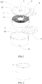
Fig.1 is a sectional view of a button-type lithium ion battery; -
Fig.2 is an exploded view of a button-type lithium ion battery; -
Fig.3 is a three-dimensional structure diagram of a center upright; -
Fig.4 is a three-dimensional structure diagram of a cover body of a shell. - This part will describe embodiments of the disclosure in detail, preferred embodiments of the disclosure are shown in drawings, and the function of drawings is to supplement the description of the word parts of the specification with drawings, so that people can intuitively and vividly understand each technical feature and the overall technical solution of the disclosure, but it cannot be understood as limiting the protective scope of the disclosure.
- In the description of the disclosure, it is to be understood that the description of the orientation, for example, the orientation or position relationship indicated by upper, lower, front, back, left, right and others is based on the orientation or position relationship shown in the drawings, which is only for conveniently describing the disclosure and simplifying the description, rather than indicating or implying that the device or element must have a specific orientation and is constructed and operated in a specific orientation, and therefore cannot be understood as limiting the disclosure.
- In the description of the disclosure, the meaning of several is single or plurality, the meaning of plurality is more than two, greater than, less than, exceeding and the like are understood as excluding the number itself, and the above, below and within are understood as including the number itself. If there is a description that the first and the second are only for the purpose of distinguishing the technical features, it cannot be understood as indicating or implying the relative importance or implicitly indicating the quantity of the indicated technical features or implicitly indicating the order of the indicated technical features.
- In the description of the disclosure, unless otherwise specified, phrases such as setting, installation and connection shall be understood in a broad sense. Those skilled in the art can reasonably determine the specific meaning of the above phrases in the disclosure in combination with the specific content of the technical solution.
- Referring to
Fig.1 andFig.2 , the button-type lithium ion battery includes ashell 4, awinding core 1, acenter uptight 2, apole 3 andtabs 5, wherein theshell 4 is internally provided with acavity 43; the windingcore 1 is arranged in thecavity 43; at least one end of thecenter uptight 2 is provided with anopening 21; thepole 3 is arranged on theshell 4, and one end of thepole 3 extends to the inside of theopening 21, and the other end of thepole 3 extends to the outside of theshell 4; thetabs 5 are connected with thewinding core 1, and thetabs 5 extend to the inside of theopening 21 and are electrically connected with thepole 3. - Referring to
Fig.2 , in this example, theshell 4 includes apedestal 41 and acover body 42, which are mutually cooperated to form thecavity 43. Thepedestal 41 and thecover body 42 which are of separation type allow the windingcore 1 in the inside to be more easily encapsulated. - In this example, the space inside the center upright 2 is skillfully utilized, and the relatively
thick pole 3 is connected with thewinding core 1 and then embedded into the inside of the center upright 2. Without limitation of thepole 3, the top of thecover body 42 can be tightly arranged with the windingcore 1, so as to relatively reduce the whole thickness of thecover body 42 and increase the utilization space of the battery. Compared with the prior art, the equivalent battery volume has higher battery capacity. - Referring to
Fig.2 , in this example, the lithium ion battery further includes anupper insulating sheet 6 and alower insulating sheet 7, which are respectively attached to the upper bottom surface of the lower bottom surface of the windingcore 1. The insulating sheets can effectively isolate the windingcore 1 from thecover body 42, thereby avoiding the accident short circuit inside the windingcore 1 caused by exterior physical factors and increasing the stability of the windingcore 1. - Referring to
Fig.1 , in this example, thepole 3 is arranged on thecover body 42. Thepole 3 is fixed and installed on thecover body 42 in advance, which is convenient for insulating treatment of thepole 3 and thecover body 42 in the process of production and improves the quality of the finished product. - Referring to
Fig.1 , in this example, thecover body 42 is provided with aliquid injection port 422 and aseal 421 which is capable of sealing theliquid injection port 422. Electrolyte is injected into the windingcore 1 through theliquid injection port 422. After the injection of electrolyte is completed, theseal 421 is used to seal theliquid injection port 422, so as to form the button-type lithium ion battery. Theliquid injection port 422 is a small through hole. By adopting a manner of injecting electrolyte via the small through hole, the electrolyte is more sufficiently injected, thereby effectively avoiding that bubbles occur inside the lithium battery and improving the rate of finished products. As an example, theseal 421 is a steel ball, and theliquid injection port 422 can be sealed by using the steel ball. It is expected that in practical application, theseal 421 can be an aluminum ball, or the sealant can also be used to seal the opening, but not limited thereto. - As an example, the material of the
cover body 42 is aluminum. In addition, the material of thecover body 42 can also be stainless steel, but not limited thereto. Aluminum is low in resistivity and small in density, so that the electrode has good conductivity and relatively small weight. - As an example, the material of the
pole 3 is copper. Thepole 3 in this example is long and thin, but selection of copper having good conductive performance as thepole 3 can also make thepole 3 have good conductive performance, thereby greatly reducing the internal resistance of thepole 3. Of course, the material of thepole 3 can also be other metal, for example, stainless steel, but not limited thereto. - As an example, as shown in
Fig.3 , thecenter upright 2 is cylindrical. The cylindrical center upright 2 decreases the fabricating difficulty of the windingcore 1 and meanwhile reduces the difference in positions between various components and increases the stability of installation. Of course, thecenter upright 2 can also be of other shapes, for example, can be rectangular, but not limited thereto. - As an example, the material of the
center upright 2 is plastic. The plastic has the advantages of corrosion resistance, insulation and aging resistance, and prevents the components inside the center upright 2 from being damaged. Of course, thecenter upright 2 can also be made of other insulating materials, for example, rubber, but not limited thereto. - The disclosure further discloses a method for fabricating the above button-type lithium ion battery, including the following steps:
- A, fabricating a winding
core 1 whose center is provided with around hole 11, a center uptight 2 whose at least one end is provided with anopening 21, apole 3 and ashell 4 which is internally provided with acavity 43; - B, inserting the center uptight 2 into the
round hole 11; - C, leading out a positive tab and a negative tab from the winding
core 1;
the positive tab being welded on theshell 4 through laser welding or ultrasonic welding;
the negative tab being welded on thepole 3 through laser welding or ultrasonic welding or resistance welding; - D, putting the winding
core 1 in thecavity 43 of theshell 4; - E, embedding the
pole 3 and a part of negative tab into theopening 21 of thecenter upright 2; and - F, sealing the
cavity 43 of theshell 4. - Through the method, the relatively thick pole is connected with the winding core and then embedded into the center uptight so that the space of the center upright is sufficiently utilized, the effect of reducing the whole thickness of the shell is taken and the effective utilization space of the battery is increased. Compared with the prior art, equivalent battery volume has higher battery capacity.
- As an example, the
shell 4 includes apedestal 41, as shown inFig.1 . Thepedestal 41 is molded by using a stretching method, and thecavity 43 accommodating the windingcore 1 is formed. Stretch molding has the advantages of high productivity and high material utilization rate. - As an example, the
shell 4 further includes acover body 42, as shown inFig.4 . Aliquid injection port 422 and a throughhole 423 used for installing thepole 3 are formed on thecover body 42 by using a punching method. Punching is high in production efficiency, convenient to operate, and easy to implement mechanization and automation. - As an example, the
pole 3 is embedded into the through hole, and sealant is injected in a gap between the outer wall surface of thepole 3 and the throughhole 423 through an injection molding manner. The sealant insulates thepole 3 from theshell 4 to prevent the short circuit inside the battery from occurring. - As an example, in step F, the following step is also included: electrolyte is injected from the
liquid injection port 422 which is sealed by using theseal 421. - As an example, the
pole 3 is protruded from the surface of thecover body 42. The protrudedpole 3 can ensure good electrical contact with the exterior. Of course, thepole 3 can also be embedded into thecover body 42, but not limited thereto. - Examples of the disclosure are described in detail above in combination with drawings, but the disclosure is not limited to the above examples. Within the knowledge scope of a person of ordinary skill in the art, various variations can also be made without departing from the spirit of the disclosure.
Claims (10)
- A button-type lithium ion battery, comprising:a shell (4) which is internally provided with a cavity (43);a winding core (1) which is arranged in the cavity (43);a center uptight (2) whose at least one end is provided with an opening (21);a pole (3) which is arranged on the shell (4), and whose one end extends to the inside of the opening (21) and whose other end extends to the outside of the shell (4);tabs (5) which are connected with the winding core (1), and which extend to the inside of the opening (21) and are electrically connected with the pole (3).
- The button-type lithium ion battery according to claim 1, further comprising an upper insulating sheet (6) and a lower insulating sheet (7), which are respectively attached to the upper bottom surface and the lower bottom surface of the winding core (1).
- The button-type lithium ion battery according to claim 1, wherein the shell (4) comprises a pedestal (41) and a cover body (42), which are mutually cooperated to form the cavity (43).
- The button-type lithium ion battery according to claim 3, wherein the cover body (42) is provided with a liquid injection port (422) and a seal (421) which is capable of sealing the liquid injection port (422).
- The button-type lithium ion battery according to claim 3, wherein the pole (3) is arranged on the cover body (42).
- The button-type lithium ion battery according to claim 1, wherein the material of the shell (4) is aluminum.
- A method for fabricating a button-type lithium ion battery, comprising the following steps:A, fabricating a winding core (1) whose center is provided with a round hole (11), a center uptight (2) whose at least one end is provided with an opening (21), a pole (3) and a shell (4) which is internally provided with a cavity (43);B, inserting the center uptight (2) into the round hole (11);C, leading out a positive tab and a negative tab from the winding core (1);
the positive tab being welded on the shell (4) through laser welding or ultrasonic welding;
the negative tab being welded on the pole (3) through laser welding or ultrasonic welding or resistance welding;D, putting the winding core (1) in the cavity (43) of the shell (4);E, embedding the pole (3) and a part of negative tab into the opening (21) of the center upright (2); andF, sealing the cavity (43) of the shell (4). - The method for fabricating the button-type lithium ion battery according to claim 7, wherein the shell (4) comprises a pedestal (41), the pedestal (41) is shaped by stretching, and the cavity (43) accommodating the winding core (1) is formed.
- The method for fabricating the button-type lithium ion battery according to claim 7, wherein the shell (4) further comprises a cover body (42), and a liquid injection port (422) and a through hole (423) used for installing the pole (3) are formed on the cover body (42) by punching.
- The method for fabricating the button-type lithium ion battery according to claim 9, wherein the pole (3) is embedded into the through hole (423), and sealant is injected between the outer wall surface of the pole (3) and the inner wall surface of the through hole (423).
Applications Claiming Priority (2)
| Application Number | Priority Date | Filing Date | Title |
|---|---|---|---|
| CN201911094423.3A CN110828885A (en) | 2019-11-11 | 2019-11-11 | Button-type cylindrical lithium-ion battery and manufacturing method thereof |
| PCT/CN2020/087693 WO2021093279A1 (en) | 2019-11-11 | 2020-04-29 | Button lithium ion battery and manufacturing method therefor |
Publications (4)
| Publication Number | Publication Date |
|---|---|
| EP3852183A1 true EP3852183A1 (en) | 2021-07-21 |
| EP3852183A4 EP3852183A4 (en) | 2022-01-12 |
| EP3852183B1 EP3852183B1 (en) | 2023-06-28 |
| EP3852183C0 EP3852183C0 (en) | 2023-06-28 |
Family
ID=69553889
Family Applications (1)
| Application Number | Title | Priority Date | Filing Date |
|---|---|---|---|
| EP20873336.0A Active EP3852183B1 (en) | 2019-11-11 | 2020-04-29 | Button lithium ion battery and manufacturing method therefor |
Country Status (5)
| Country | Link |
|---|---|
| US (1) | US11984558B2 (en) |
| EP (1) | EP3852183B1 (en) |
| JP (1) | JP2022513581A (en) |
| CN (1) | CN110828885A (en) |
| WO (1) | WO2021093279A1 (en) |
Families Citing this family (16)
| Publication number | Priority date | Publication date | Assignee | Title |
|---|---|---|---|---|
| CN110828885A (en) * | 2019-11-11 | 2020-02-21 | 中山市众旺德新能源科技有限公司 | Button-type cylindrical lithium-ion battery and manufacturing method thereof |
| CN211907486U (en) | 2020-03-03 | 2020-11-10 | 珠海冠宇电池股份有限公司 | Shell assembly of button cell, button cell and electronic product |
| JP7381569B2 (en) * | 2020-05-18 | 2023-11-15 | 寧徳新能源科技有限公司 | Batteries and electrical devices equipped with said batteries |
| EP4152489A4 (en) | 2020-06-03 | 2024-02-28 | Zhuhai CosMX Battery Co., Ltd. | BUTTON BATTERY AND MANUFACTURING METHOD THEREFOR, AND ELECTRONIC DEVICE |
| WO2021244272A1 (en) | 2020-06-03 | 2021-12-09 | 珠海冠宇电池股份有限公司 | Button-type battery and electronic device |
| CN112002834A (en) * | 2020-06-12 | 2020-11-27 | 珠海市讯达科技有限公司 | Button battery and manufacturing method thereof |
| CN111900274A (en) * | 2020-08-04 | 2020-11-06 | 珠海冠宇电池股份有限公司 | Button cell and preparation method thereof |
| US11715868B2 (en) * | 2020-09-11 | 2023-08-01 | Greatbatch Ltd. | Electrochemical cell casing having an electrolyte fill port with an embossed rim lid design |
| WO2022065776A1 (en) * | 2020-09-25 | 2022-03-31 | 주식회사 엘지에너지솔루션 | Button-type secondary battery |
| CN114267909A (en) * | 2021-12-17 | 2022-04-01 | 马鞍山大仓精工科技有限公司 | Lithium battery shell and manufacturing method thereof |
| CN114142125B (en) * | 2021-12-28 | 2025-08-08 | 欣旺达动力科技股份有限公司 | Battery cells and battery modules |
| CN216872110U (en) * | 2022-02-18 | 2022-07-01 | 宁德时代新能源科技股份有限公司 | A collet, battery monomer, battery and consumer for battery monomer |
| CN115084796B (en) * | 2022-06-14 | 2025-02-11 | 东莞锂威能源科技有限公司 | A guide pin composite button battery |
| CN115077335A (en) * | 2022-06-22 | 2022-09-20 | 力神(青岛)新能源有限公司 | Rolling needle checking tool for lithium ion power battery pole group |
| CN115377566B (en) * | 2022-08-30 | 2026-04-24 | 中山市众旺德新能源科技有限公司 | A hard-shell arc-shaped battery and a method for manufacturing the arc-shaped battery |
| CN117039102B (en) * | 2023-08-25 | 2025-09-26 | 蜂巢能源科技股份有限公司 | Long cell modules, battery packs and power units |
Family Cites Families (22)
| Publication number | Priority date | Publication date | Assignee | Title |
|---|---|---|---|---|
| JP3752930B2 (en) * | 1999-11-17 | 2006-03-08 | 新神戸電機株式会社 | Cylindrical lithium-ion battery |
| JP4292453B2 (en) * | 2002-01-23 | 2009-07-08 | 株式会社デンソー | Manufacturing method of non-aqueous electrolyte battery |
| US7341802B1 (en) * | 2004-03-25 | 2008-03-11 | Quallion Llc | Feedthrough assembly and method |
| JP2008262827A (en) * | 2007-04-12 | 2008-10-30 | Hitachi Maxell Ltd | Coin type non-aqueous electrolyte secondary battery |
| WO2010089152A1 (en) * | 2009-02-09 | 2010-08-12 | Varta Microbattery Gmbh | Button cells and method for producing same |
| DE102009060800A1 (en) * | 2009-06-18 | 2011-06-09 | Varta Microbattery Gmbh | Button cell with winding electrode and method for its production |
| CN201773903U (en) | 2010-07-02 | 2011-03-23 | 博特科科技(深圳)有限公司 | Button lithium battery |
| WO2012073331A1 (en) * | 2010-11-30 | 2012-06-07 | 日立ビークルエナジー株式会社 | Rechargeable battery and rechargeable battery module |
| CN102064339A (en) * | 2010-12-21 | 2011-05-18 | 王正伟 | Lithium battery and assembling method thereof |
| CN104577192A (en) * | 2015-01-05 | 2015-04-29 | 国家电网公司 | High-rate lithium ion power battery and manufacturing method thereof |
| CN106159350B (en) * | 2015-04-27 | 2019-04-26 | 深圳金山电池有限公司 | A kind of coin shape lithium ion secondary battery and preparation method thereof |
| JP6731831B2 (en) * | 2016-01-15 | 2020-07-29 | セイコーインスツル株式会社 | Electrochemical cell |
| CN206210965U (en) * | 2016-12-01 | 2017-05-31 | 珠海市至力电池有限公司 | Wind the stopper and winding fastening lithium ionic cell of fastening lithium ionic cell |
| CN107394066A (en) * | 2017-06-26 | 2017-11-24 | 湖南三迅新能源科技有限公司 | Battery cover board and its processing method |
| DE212018000351U1 (en) * | 2017-11-17 | 2020-07-23 | Shenzhen Kedali Industry Co., Ltd | aluminum casing |
| CN108023037B (en) * | 2017-12-15 | 2024-06-25 | 珠海微矩实业有限公司 | Button cell |
| CN208045560U (en) * | 2018-03-15 | 2018-11-02 | 天能电池集团有限公司 | A kind of accumulator terminal post sealing structure |
| CN108520936A (en) * | 2018-03-16 | 2018-09-11 | 深圳市沃特玛电池有限公司 | An aluminum shell cylindrical battery |
| CN209133544U (en) * | 2018-11-30 | 2019-07-19 | 苏州宇量电池有限公司 | A kind of column lithium ion battery with resistance dirt insulating trip |
| CN110289451A (en) | 2019-07-03 | 2019-09-27 | 惠州市金芯科技有限公司 | A kind of button lithium battery and preparation method thereof |
| CN210956889U (en) * | 2019-11-11 | 2020-07-07 | 中山市众旺德新能源科技有限公司 | Button type columnar lithium ion battery |
| CN110828885A (en) * | 2019-11-11 | 2020-02-21 | 中山市众旺德新能源科技有限公司 | Button-type cylindrical lithium-ion battery and manufacturing method thereof |
-
2019
- 2019-11-11 CN CN201911094423.3A patent/CN110828885A/en active Pending
-
2020
- 2020-04-29 WO PCT/CN2020/087693 patent/WO2021093279A1/en not_active Ceased
- 2020-04-29 EP EP20873336.0A patent/EP3852183B1/en active Active
- 2020-04-29 JP JP2021521773A patent/JP2022513581A/en active Pending
- 2020-06-20 US US16/907,178 patent/US11984558B2/en active Active
Also Published As
| Publication number | Publication date |
|---|---|
| WO2021093279A1 (en) | 2021-05-20 |
| CN110828885A (en) | 2020-02-21 |
| EP3852183B1 (en) | 2023-06-28 |
| US20210143484A1 (en) | 2021-05-13 |
| EP3852183A4 (en) | 2022-01-12 |
| EP3852183C0 (en) | 2023-06-28 |
| US11984558B2 (en) | 2024-05-14 |
| JP2022513581A (en) | 2022-02-09 |
Similar Documents
| Publication | Publication Date | Title |
|---|---|---|
| US11984558B2 (en) | Button-type lithium ion battery and method for fabricating same | |
| CN212750989U (en) | Button cell | |
| CN107706334B (en) | Soft package battery | |
| CN104377335B (en) | High capacity lithium ion battery bag | |
| CN210224213U (en) | Winding type button battery with integrated insulation tabs | |
| CN203932227U (en) | A kind of lithium ion battery | |
| CN115413384B (en) | Battery and electric device having the battery | |
| CN203521509U (en) | High-capacity lithium ion battery pack | |
| CN207868254U (en) | Battery | |
| CN210956889U (en) | Button type columnar lithium ion battery | |
| CN114069019B (en) | Button battery housing, button battery and assembly method | |
| CN203690393U (en) | Novel lithium battery integration module | |
| CN205609693U (en) | Electrochemistry energy memory | |
| CN204088447U (en) | Secondary cell | |
| CN221282179U (en) | Rechargeable lithium battery capable of being automatically produced | |
| CN221353119U (en) | Battery devices and electronic devices | |
| CN207834478U (en) | A button-type polymer lithium-ion battery | |
| CN209169259U (en) | A kind of anticreep cell reservoir of lithium-ion-power cell production | |
| CN210467971U (en) | Pole for capacitive nickel-hydrogen power battery | |
| CN208722934U (en) | Battery cover plate assembly and battery | |
| CN221727382U (en) | Top cover assembly and battery cell | |
| CN212625986U (en) | Cells, batteries, electronic equipment and molds | |
| CN217062309U (en) | Power battery top cover and power battery module | |
| CN221201477U (en) | Novel lithium ion battery | |
| CN223230476U (en) | Battery cell and charging device |
Legal Events
| Date | Code | Title | Description |
|---|---|---|---|
| STAA | Information on the status of an ep patent application or granted ep patent |
Free format text: STATUS: UNKNOWN |
|
| STAA | Information on the status of an ep patent application or granted ep patent |
Free format text: STATUS: THE INTERNATIONAL PUBLICATION HAS BEEN MADE |
|
| PUAI | Public reference made under article 153(3) epc to a published international application that has entered the european phase |
Free format text: ORIGINAL CODE: 0009012 |
|
| STAA | Information on the status of an ep patent application or granted ep patent |
Free format text: STATUS: REQUEST FOR EXAMINATION WAS MADE |
|
| 17P | Request for examination filed |
Effective date: 20210412 |
|
| AK | Designated contracting states |
Kind code of ref document: A1 Designated state(s): AL AT BE BG CH CY CZ DE DK EE ES FI FR GB GR HR HU IE IS IT LI LT LU LV MC MK MT NL NO PL PT RO RS SE SI SK SM TR |
|
| A4 | Supplementary search report drawn up and despatched |
Effective date: 20211213 |
|
| RIC1 | Information provided on ipc code assigned before grant |
Ipc: H01M 50/531 20210101ALI20211207BHEP Ipc: H01M 10/0587 20100101ALI20211207BHEP Ipc: H01M 10/04 20060101ALI20211207BHEP Ipc: H01M 10/058 20100101ALI20211207BHEP Ipc: H01M 10/0525 20100101AFI20211207BHEP |
|
| STAA | Information on the status of an ep patent application or granted ep patent |
Free format text: STATUS: EXAMINATION IS IN PROGRESS |
|
| 17Q | First examination report despatched |
Effective date: 20220714 |
|
| DAV | Request for validation of the european patent (deleted) | ||
| DAX | Request for extension of the european patent (deleted) | ||
| GRAP | Despatch of communication of intention to grant a patent |
Free format text: ORIGINAL CODE: EPIDOSNIGR1 |
|
| STAA | Information on the status of an ep patent application or granted ep patent |
Free format text: STATUS: GRANT OF PATENT IS INTENDED |
|
| INTG | Intention to grant announced |
Effective date: 20230324 |
|
| GRAS | Grant fee paid |
Free format text: ORIGINAL CODE: EPIDOSNIGR3 |
|
| GRAA | (expected) grant |
Free format text: ORIGINAL CODE: 0009210 |
|
| STAA | Information on the status of an ep patent application or granted ep patent |
Free format text: STATUS: THE PATENT HAS BEEN GRANTED |
|
| AK | Designated contracting states |
Kind code of ref document: B1 Designated state(s): AL AT BE BG CH CY CZ DE DK EE ES FI FR GB GR HR HU IE IS IT LI LT LU LV MC MK MT NL NO PL PT RO RS SE SI SK SM TR |
|
| REG | Reference to a national code |
Ref country code: CH Ref legal event code: EP |
|
| REG | Reference to a national code |
Ref country code: AT Ref legal event code: REF Ref document number: 1583543 Country of ref document: AT Kind code of ref document: T Effective date: 20230715 |
|
| REG | Reference to a national code |
Ref country code: IE Ref legal event code: FG4D |
|
| REG | Reference to a national code |
Ref country code: DE Ref legal event code: R096 Ref document number: 602020013144 Country of ref document: DE |
|
| U01 | Request for unitary effect filed |
Effective date: 20230705 |
|
| U07 | Unitary effect registered |
Designated state(s): AT BE BG DE DK EE FI FR IT LT LU LV MT NL PT SE SI Effective date: 20230718 |
|
| REG | Reference to a national code |
Ref country code: LT Ref legal event code: MG9D |
|
| PG25 | Lapsed in a contracting state [announced via postgrant information from national office to epo] |
Ref country code: NO Free format text: LAPSE BECAUSE OF FAILURE TO SUBMIT A TRANSLATION OF THE DESCRIPTION OR TO PAY THE FEE WITHIN THE PRESCRIBED TIME-LIMIT Effective date: 20230928 |
|
| PG25 | Lapsed in a contracting state [announced via postgrant information from national office to epo] |
Ref country code: RS Free format text: LAPSE BECAUSE OF FAILURE TO SUBMIT A TRANSLATION OF THE DESCRIPTION OR TO PAY THE FEE WITHIN THE PRESCRIBED TIME-LIMIT Effective date: 20230628 Ref country code: HR Free format text: LAPSE BECAUSE OF FAILURE TO SUBMIT A TRANSLATION OF THE DESCRIPTION OR TO PAY THE FEE WITHIN THE PRESCRIBED TIME-LIMIT Effective date: 20230628 Ref country code: GR Free format text: LAPSE BECAUSE OF FAILURE TO SUBMIT A TRANSLATION OF THE DESCRIPTION OR TO PAY THE FEE WITHIN THE PRESCRIBED TIME-LIMIT Effective date: 20230929 |
|
| PG25 | Lapsed in a contracting state [announced via postgrant information from national office to epo] |
Ref country code: SK Free format text: LAPSE BECAUSE OF FAILURE TO SUBMIT A TRANSLATION OF THE DESCRIPTION OR TO PAY THE FEE WITHIN THE PRESCRIBED TIME-LIMIT Effective date: 20230628 |
|
| PG25 | Lapsed in a contracting state [announced via postgrant information from national office to epo] |
Ref country code: ES Free format text: LAPSE BECAUSE OF FAILURE TO SUBMIT A TRANSLATION OF THE DESCRIPTION OR TO PAY THE FEE WITHIN THE PRESCRIBED TIME-LIMIT Effective date: 20230628 |
|
| PG25 | Lapsed in a contracting state [announced via postgrant information from national office to epo] |
Ref country code: IS Free format text: LAPSE BECAUSE OF FAILURE TO SUBMIT A TRANSLATION OF THE DESCRIPTION OR TO PAY THE FEE WITHIN THE PRESCRIBED TIME-LIMIT Effective date: 20231028 |
|
| PG25 | Lapsed in a contracting state [announced via postgrant information from national office to epo] |
Ref country code: SM Free format text: LAPSE BECAUSE OF FAILURE TO SUBMIT A TRANSLATION OF THE DESCRIPTION OR TO PAY THE FEE WITHIN THE PRESCRIBED TIME-LIMIT Effective date: 20230628 Ref country code: SK Free format text: LAPSE BECAUSE OF FAILURE TO SUBMIT A TRANSLATION OF THE DESCRIPTION OR TO PAY THE FEE WITHIN THE PRESCRIBED TIME-LIMIT Effective date: 20230628 Ref country code: RO Free format text: LAPSE BECAUSE OF FAILURE TO SUBMIT A TRANSLATION OF THE DESCRIPTION OR TO PAY THE FEE WITHIN THE PRESCRIBED TIME-LIMIT Effective date: 20230628 Ref country code: IS Free format text: LAPSE BECAUSE OF FAILURE TO SUBMIT A TRANSLATION OF THE DESCRIPTION OR TO PAY THE FEE WITHIN THE PRESCRIBED TIME-LIMIT Effective date: 20231028 Ref country code: ES Free format text: LAPSE BECAUSE OF FAILURE TO SUBMIT A TRANSLATION OF THE DESCRIPTION OR TO PAY THE FEE WITHIN THE PRESCRIBED TIME-LIMIT Effective date: 20230628 Ref country code: CZ Free format text: LAPSE BECAUSE OF FAILURE TO SUBMIT A TRANSLATION OF THE DESCRIPTION OR TO PAY THE FEE WITHIN THE PRESCRIBED TIME-LIMIT Effective date: 20230628 |
|
| PG25 | Lapsed in a contracting state [announced via postgrant information from national office to epo] |
Ref country code: PL Free format text: LAPSE BECAUSE OF FAILURE TO SUBMIT A TRANSLATION OF THE DESCRIPTION OR TO PAY THE FEE WITHIN THE PRESCRIBED TIME-LIMIT Effective date: 20230628 |
|
| REG | Reference to a national code |
Ref country code: DE Ref legal event code: R097 Ref document number: 602020013144 Country of ref document: DE |
|
| U20 | Renewal fee for the european patent with unitary effect paid |
Year of fee payment: 5 Effective date: 20240325 |
|
| PLBE | No opposition filed within time limit |
Free format text: ORIGINAL CODE: 0009261 |
|
| STAA | Information on the status of an ep patent application or granted ep patent |
Free format text: STATUS: NO OPPOSITION FILED WITHIN TIME LIMIT |
|
| 26N | No opposition filed |
Effective date: 20240402 |
|
| PG25 | Lapsed in a contracting state [announced via postgrant information from national office to epo] |
Ref country code: MC Free format text: LAPSE BECAUSE OF FAILURE TO SUBMIT A TRANSLATION OF THE DESCRIPTION OR TO PAY THE FEE WITHIN THE PRESCRIBED TIME-LIMIT Effective date: 20230628 |
|
| PG25 | Lapsed in a contracting state [announced via postgrant information from national office to epo] |
Ref country code: MC Free format text: LAPSE BECAUSE OF FAILURE TO SUBMIT A TRANSLATION OF THE DESCRIPTION OR TO PAY THE FEE WITHIN THE PRESCRIBED TIME-LIMIT Effective date: 20230628 |
|
| REG | Reference to a national code |
Ref country code: CH Ref legal event code: PL |
|
| PG25 | Lapsed in a contracting state [announced via postgrant information from national office to epo] |
Ref country code: CH Free format text: LAPSE BECAUSE OF NON-PAYMENT OF DUE FEES Effective date: 20240430 |
|
| PG25 | Lapsed in a contracting state [announced via postgrant information from national office to epo] |
Ref country code: IE Free format text: LAPSE BECAUSE OF NON-PAYMENT OF DUE FEES Effective date: 20240429 |
|
| U20 | Renewal fee for the european patent with unitary effect paid |
Year of fee payment: 6 Effective date: 20250410 |
|
| PG25 | Lapsed in a contracting state [announced via postgrant information from national office to epo] |
Ref country code: CY Free format text: LAPSE BECAUSE OF FAILURE TO SUBMIT A TRANSLATION OF THE DESCRIPTION OR TO PAY THE FEE WITHIN THE PRESCRIBED TIME-LIMIT; INVALID AB INITIO Effective date: 20200429 |
|
| PG25 | Lapsed in a contracting state [announced via postgrant information from national office to epo] |
Ref country code: HU Free format text: LAPSE BECAUSE OF FAILURE TO SUBMIT A TRANSLATION OF THE DESCRIPTION OR TO PAY THE FEE WITHIN THE PRESCRIBED TIME-LIMIT; INVALID AB INITIO Effective date: 20200429 |
|
| PGFP | Annual fee paid to national office [announced via postgrant information from national office to epo] |
Ref country code: GB Payment date: 20260327 Year of fee payment: 7 |