[utility model content]
The purpose of this utility model is to provide a kind of simple in structure, and simplified manufacturing process, security performance is high, maintenance is quick, and the applicable high capacity lithium ion battery bag of producing in enormous quantities.
To achieve these goals, the utility model adopts following technical scheme: a kind of high capacity lithium ion battery bag, comprises a housing, lid, a plurality of battery core, an electric connection chip module and two poles; In described housing, be provided with a plurality of battery core accepting grooves; Described cover assembling is on described housing; Each battery core comprises that a positive plate and a negative plate and each battery core are contained in a corresponding battery core accepting groove; Described electric connection chip module comprises a plurality of upper contact chips and a plurality of lower contact chip, integrally formed and the part of described a plurality of upper contact chip and described lid is exposed to described lid, one-body molded and the part of described a plurality of lower contact chip and described housing is exposed to described housing, described a plurality of upper contact chip and described a plurality of lower contact chip are arranged at respectively the two ends of described a plurality of battery cores, the exposed part of described a plurality of upper contact chips and described a plurality of lower contact chips and described a plurality of battery cores just and/or negative plate is in electrical contact makes described a plurality of battery core form connection in series-parallel battery core; Described two poles are arranged at respectively total positive pole and total negative pole place of connection in series-parallel battery core.
As a kind of improvement of the utility model high capacity lithium ion battery bag, described battery core accepting groove is the cylinder of independently a plurality of and upper end open, forms a plurality of the first receiving spaces between the sidewall of accepting groove or between the sidewall of accepting groove and housing madial wall.
A kind of improvement as the utility model high capacity lithium ion battery bag, described a plurality of upper contact chip and described a plurality of lower contact chip structure are identical, on each, contact chip comprises the upper matrix of a rectangle sheet and the upper electrical contact site that at least one upper surface from described upper matrix protrudes, and each lower contact chip comprises the lower substrate of a rectangle sheet and the lower portion in electrical contact that at least one upper surface from described lower substrate protrudes.
As a kind of improvement of the utility model high capacity lithium ion battery bag, wherein between adjacent two the upper contact chips in the upper contact chip of a part, be also connected with a upper electrical linking arm; Wherein between adjacent two the lower contact chips in the lower contact chip of a part, be also connected with the next lower arm that is electrically connected.
As a kind of improvement of the utility model high capacity lithium ion battery bag, on each, contact chip is also being provided with rupture pressure disc near electrical contact site place described; Each lower contact chip is also being provided with lower rupture pressure disc near described lower portion in electrical contact place.
As a kind of improvement of the utility model high capacity lithium ion battery bag, the described electrical contact site that the exposed portion after described a plurality of upper contact chips and described lid are one-body molded is described upper contact chip and described upper rupture pressure disc; Portion lower in electrical contact and lower rupture pressure disc that exposed part after described a plurality of lower contact chip and housing are one-body molded is described lower contact chip; The two ends of each battery core are welded with respectively positive flow collection sheet and the negative flow collection sheet being electrically connected to positive plate and negative plate, and on each, positive flow collection sheet or the negative flow collection sheet of electrical contact site and each lower portion in electrical contact and each battery core are in electrical contact.
As a kind of improvement of the utility model high capacity lithium ion battery bag, described lid and described housing offer guiding gutter on opposing surface, offer a plurality of upper welding holes, a plurality of upper safety valve open hole and a plurality of upper return port in described upper guiding gutter; On each, the position of welding hole is corresponding to a upper electrical contact site, and on each, the position of safety valve open hole is corresponding to a upper rupture pressure disc, and the position of each return port is corresponding to first receiving space; The opposing surface of the diapire of described housing and described lid offers lower guiding gutter, in described lower guiding gutter, offer a plurality of lower welding holes, a plurality of lower safety valve open hole and a plurality of lower return port, the position of each lower welding hole is corresponding to portion in electrical contact under, the position of each lower safety valve open hole is corresponding to a lower rupture pressure disc, and the position of each lower return port is corresponding to first receiving space.
A kind of improvement as the utility model high capacity lithium ion battery bag, described lid also comprises that one towards the lower surface of described housing, described lower surface extends a plurality of portions that cover that interconnect, described a plurality of upper contact chip is arranged at described a plurality of covering in portion, and each portion of covering is cylindric and is fastened on a corresponding battery core accepting groove and each covers and in portion, accommodates a conductive pole that is electrically connected to a corresponding battery core.
As a kind of improvement of the utility model high capacity lithium ion battery bag, described conductive pole is welded on described electrical contact site, and described conductive pole comprises base portion and from the outward extending inserting column of base portion; Describedly be contained in battery core in battery core accepting groove the battery core top cover of insulation is installed towards one end of lid, the central position of described battery core top cover is provided with resilient clamp sheet, and described resilient clamp sheet is and does not seal round table-likely, and it is provided with the region of accommodating of inserting for inserting column.
As a kind of improvement of the utility model high capacity lithium ion battery bag, described in accommodate battery core in parallel accepting groove bottom by a radiating tube UNICOM together.
Compared with prior art, the utility model high capacity lithium ion battery bag has following advantage:
1) owing to being electrically connected chip module and lid, housing is one-body molded, belong to a kind of technique of burying underground in advance, the technique that it gets up a plurality of monomer ferric phosphate lithium cell series and parallel connections with respect to the mode of traditional employing lock screw or spot welding, has saved a lot of operations, has improved production efficiency;
2) between described upper contact chip or lower contact chip, be also connected with electrical linking arm or lower electric connection arm, this upper and lower electric connection arm large electric current by time just can fuse, ensured the safe handling of power brick;
3) save box hat and the block of traditional cylindrical battery, reduced Material Cost;
4) between the bottom of battery core in parallel place accepting groove, be UNICOM mutually, be convenient to improve the capacity of cell, meanwhile, when certain cell generates heat because of fault, its heat can be shared by numerous battery cores, prevents the risk of the secure context that battery brings because heat increases severely;
5) convenient maintenance after sale.
[embodiment]
In order to make, the purpose of this utility model, technical scheme and useful technique effect are more clear to be understood, below in conjunction with the drawings and specific embodiments, the utility model is further elaborated.Should be understood that, the embodiment of describing in this specification is only used to explain the utility model, is not in order to limit the utility model.
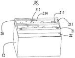
Please refer to shown in Fig. 1 to Fig. 4, the high capacity lithium ion battery bag 100 that the utility model the first execution mode provides, comprise a housing 10, lid 20, a plurality of battery core 30, one be electrically connected chip module 40 and two poles 50.
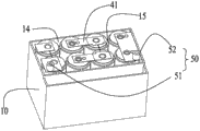
Please refer to Fig. 5 to Fig. 9, the rectangular frame structure of described housing 10 and being made by plastic shaping, it comprises a diapire 11 and the sidewall 12 that extends upward formation from diapire surrounding.In described housing 10, be provided with a plurality of battery core accepting grooves 13 on described diapire 11, each battery core accepting groove 13 is the cylinder of a upper end open.Between the sidewall of described accepting groove 13 or between the sidewall of described accepting groove 13 and the madial wall of described housing 10, form a plurality of the first receiving spaces 14.In present embodiment, between described a plurality of battery core accepting grooves 13, interval arranges, and is also provided with a reinforcement 15 between two battery core accepting grooves 13.Described battery core accepting groove 13 materials are PP or PE, the corrosion of ability lithium-ion electrolyte.The diapire 11 of described housing 10 and described sidewall 12 all offer lower guiding gutter 111 on opposing surface, offer a plurality of lower welding holes 112, a plurality of lower safety valve open hole 113 and a plurality of return port 114 in described lower guiding gutter 111.
The rectangular block structure of described lid 20 and being made by plastic shaping, described lid 20 is for being combined in the opposing side of described housing 10 and described diapire 11.Described lid 20 comprise a upper surface 21 and one for be incorporated into described housing 10 with the opposing lower surface 22 of described upper surface 21.The upper surface 21 of described lid 20 offers guiding gutter 211, offers and be through to a plurality of upper welding hole 212 of described lower surface 22, a plurality of upper safety valve open hole 213 and a plurality of upper return port 214 in described upper guiding gutter 211.
Each battery core 30 is the cylindric and inner electrolyte that contains, and the diameter of each battery core 30 is corresponding to the diameter of each battery core accepting groove 13.In other embodiments, each battery core 30 is rectangular-shaped or other shapes also, corresponding, and the shape of each battery core accepting groove 13 is also rectangular-shaped or other shapes.13 li of described battery cores 30 of accommodating of described battery core accepting groove mainly contain two kinds of connected modes, one is series connection, it two is in parallel, for bottom and/or the top of accommodating the battery core accepting groove 13 of battery core in parallel, be also provided with radiating tube 60, battery core accepting groove 13 UNICOMs that these radiating tubes 60 contain battery core in parallel by these form an integral body, radiating tube 60 can adopt various structures, and in the utility model, it selects the copper pipe of bending to be made.
Each battery core 30 is wound mutually by a positive plate 31 and a negative plate 32, (by the mode of ultrasonic wave, electric resistance welding or Laser Welding) anode collection sheet 71 (as shown in figure 10) being electrically connected to described positive plate 31 in the welding of one end of each battery core 30, (by the mode of ultrasonic wave, electric resistance welding or Laser Welding) negative pole currect collecting sheet 72 (as shown in figure 10) being electrically connected to described negative plate 32 in other end welding.
Described electric connection chip module 40 comprises a plurality of upper contact chips 41 and a plurality of lower contact chip 42, and on each, lower contact chip 42 structures of contact chip 41 and each are identical and be all made of metal.On each, contact chip 41 comprises the upper matrix 411 of a rectangle sheet, on each, the upper surface of matrix 411 protrudes electrical contact site 412 at least one, and described upper electrical contact site 412 its essence is that the surface of matrix 411 is to the vaulted kick of being with of upper process formation.Wherein between adjacent two upper contact chips 41 of the upper contact chip 41 of a part, be also connected with a upper electrical linking arm 413, the area of described upper electrical contact arm 413, much smaller than the area of described upper matrix 411, so surpasses a predetermined value at the electric current by being electrically connected property linking arm 413 on this and just can fuse.On each, matrix 411 is also provided with a upper rupture pressure disc 414 in the side of upper electrical contact site 413, rupture pressure disc 414 and described upper matrix 411 is formed in one and on this, thickness of rupture pressure disc 414 is less than described upper matrix 411 thickness on this.Same, each lower contact chip 42 also comprises the lower substrate 421 of a rectangle sheet, each lower substrate 421 upper surface protrudes at least one lower portion 412 in electrical contact, wherein between adjacent two lower contact chips 42 of the upper contact chip 41 of a part, is also connected with and under one, is electrically connected arm 423.
Described two poles 50 are made of metal and comprise a columniform positive terminal 51 and a columniform negative terminal 52.
In processing and manufacturing and assemble in the process of described high capacity lithium ion battery bag 100, first processing metal part, metalwork comprises electric connection chip module 40, positive and negative pole 51,52, radiating tube 70, again the metalwork of part is put into the injection molding mould that is respectively used to form described housing 10 and described lid 20, wherein, described upper contact chip 41, described positive and negative pole 51,52 are put into the mould that is used to form described lid 20, and described lower contact chip 42 and described radiating tube 60 are put in forming described housing 10 moulds.In other embodiments, described radiating tube 60 also can be put in forming the mould of lid 20 or putting in the mould that forms housing 10 and described lid 20.Then injection mo(u)lding inside is embedded with plastic casing 10 and the lid 20 of metalwork.
In the process of moulding, the opposing surface (being the opposing surface of diapire 11 and described lid 20 after housing 10 and lid 20 combine) of the diapire 11 of housing 10 and described sidewall 12 molds lower guiding gutter 111.In described lower guiding gutter 111, offer a plurality of lower welding holes 112, a plurality of lower safety valve open hole 113 and a plurality of lower return port 114.The upper surface 21 of lid 20 (being the opposing surface of lid 20 and described housing 10 after housing 10 and lid 20 combine) molds upper guiding gutter 211.In described upper guiding gutter 211, offer a plurality of upper welding holes 212, a plurality of upper safety valve open hole 213 and a plurality of upper return port 214.
The position of the concrete setting of described upper contact chip 41 in lid 20 is such: the upper matrix 411 of rectangle sheet is embedded among the plastic material of lid, portion in electrical contact 412 and upper rupture pressure disc 414 out exposed and lower surface in lid 20 22 from lid 20 that upper matrix 411 upper surfaces protrude, it is mutually corresponding with positive plate 31 or the negative plate 32 of battery core 30.The concrete structure of described lower contact chip 42 in housing 10 is such: the lower substrate 421 of rectangle sheet is embedded among the plastic material of housing 10, the portion 4222 lower in electrical contact that lower substrate 421 upper surfaces protrude is the out exposed and bottom in a corresponding battery core accepting groove 13 from housing, and it is mutually corresponding with positive plate 31 or the negative plate 32 of a corresponding battery core 30.For the ease of being assembled into series-parallel battery core, conventionally will between two adjacent upper contact chips 41 of a part, pass through a first mutual rear reshaping in electrical contact of upper electrical linking arm 413 together, will between two adjacent lower contact chips 42 of a part, under one, be electrically connected the first rear reshaping in electrical contact mutually of arm 423 together.
Then, all battery cores 30 are all packed in all battery core accepting grooves 13, then compress, the positive flow collection sheet 71 of each battery core 30 one end or negative pole currect collecting sheet 72 just can butt to portion 412 in electrical contact under of a corresponding lower contact chip 42.The position of each lower welding hole 112 is corresponding to portion 422 in electrical contact under of lower contact chip 41, the position of each lower safety valve open hole 113 is corresponding to one on lower contact chip 42 lower rupture pressure disc 424, and the position of each lower return port 114 is corresponding to first receiving space 14 forming between the sidewall of battery core accepting groove 13 or between the sidewall of battery core accepting groove and the madial wall of housing 11.By the mode of laser spot welding, by the lower welding hole 112 that arranges on lower guiding gutter 111, the plus or minus utmost point flow collection sheet 71,72 of each battery core 30 and the portion 422 lower in electrical contact that is embedded in the lower contact chip 42 in housing 10 are welded together.
Then described lid 20 is incorporated on described housing 10, wherein said lower surface 22 is towards described housing 10, and one end of each battery core 30 is towards described lid 20.On each, the position of welding hole 212 is corresponding to a upper electrical contact site 412 of upper contact chip 41, on each, the position of safety valve open hole 213 is corresponding to one on upper contact chip 41 upper rupture pressure disc 414, and on each, the position of return port 73 is corresponding to first receiving space 14 forming between the sidewall of battery core accepting groove 13 or between the sidewall of battery core accepting groove and the madial wall of housing 11.By the mode of laser spot welding, by the upper welding hole 212 that arranges on upper guiding gutter 211, the plus or minus utmost point flow collection sheet 71,72 of each battery core 30 and the upper electrical contact site 412 that is embedded in the upper contact chip 41 in lid 20 are welded together.
Finally; with sealing strip, upper guiding gutter 111 and lower guiding gutter 211 are sealed again; lid and housing is welded together by the mode of ultrasonic bond; the liquid injection hole of offering from lid again carries out fluid injection to each battery core accepting groove of battery core is housed; with sealing strip, the guiding gutter of lid upper surface is sealed again; load onto baffle, the assembling of a complete described large capacity lithium Guo power brick 100 like this.The exposed part of described a plurality of upper contact chips 41 and described a plurality of lower contact chips 41 and described a plurality of battery cores just and/or negative plate 31,32 (present embodiment, battery core just and/or negative plate 31,32 also in electrical contact by positive and negative flow collection sheet and upper contact chip 41, lower contact chip) in electrical contactly make described a plurality of battery core 30 form connection in series-parallel battery cores; Described two poles 50 are arranged at respectively total positive pole and total negative pole place of connection in series-parallel battery core.Described two poles are connected to load by circuit again.
Please refer to shown in Figure 11-15, the utility model also provides the second execution mode that a kind of high capacity lithium ion battery bag 300 is provided, itself and the first high capacity lithium ion battery bag 100 difference are structurally: the upper contact chip 41 in lid 90 not as the first high capacity lithium ion battery bag, be directly welded on battery core on one end of lid 90, but battery core 30 towards a termination electrode of lid with the mode of plug be electrically connected sheet and be electrically connected.
Specifically: the lid 90 of the high capacity lithium ion battery bag 300 of the second execution mode comprises that one towards the lower surface 91 of described housing 10, described lower surface 91 extends a plurality of portions that cover 92 that interconnect, each covers portion 92 is the cylindric and corresponding metal conductive pole 93 of accommodating, and each covers portion 92 and is fastened on a corresponding battery core accepting groove for cylindric and corresponding.Described conductive pole 93 comprises the base portion 931 of a circle and from the outward extending columniform inserting column 932 of base portion 931.Described in being placed on, described base portion 931 covers portion 92 interior and in electrical contact in a corresponding electrical contact site 412.
The one end towards described lid that is contained in the battery core 30 in battery core accepting groove is provided with the battery core top cover 33 of insulation, the central position of described battery core top cover 33 is provided with holding piece 34, described holding piece 34 be do not seal round table-like, the diameter of the upper-lower section of this round platform is all greater than the diameter in stage casing, its be provided with for conductive pole 34, insert accommodate region 341, also the positive flow collection sheet 71 on one end of described lid 90 or negative pole flow 72 electrically weld together clamping sheet 34 with battery core 30.So, when lid 90 is combined in described housing 10, on each, the upper electrical contact site 412 of contact chip 41 inserts by a corresponding conductive pole 93 positive flow collection sheet 71 or the negative flow collection sheet 72 that is electrically connected to a corresponding battery core 30 in a corresponding holding piece 34.Describedly cover in portion 92 corresponding each battery core and also offer liquid injection hole, can carry out by these liquid injection holes the fluid injection of battery.
Connected mode with the connection in series-parallel battery core in large-capacity battery pack of the present utility model is described as follows Figure 3 shows that example:
This connection in series-parallel battery core comprises 8 cells, and its numbering is designated as respectively I-VIII.First with two respectively have a portion in electrical contact first on contact chip be connected to and be numbered I, the positive pole of two cells of III is also drawn total positive terminal, on aforesaid two first, between contact chip, be also provided with linking arm, to be numbered I subsequently, the negative pole of two cells of III respectively be numbered II, the positive pole of two cells of IV is electrically connected by two first time contact chips, these two first time contact chips include between two portions in electrical contact and two first time contact chips and are connected with linking arm, to be numbered II again, the negative pole of two cells of IV respectively be numbered V, the positive pole of two cells of VII is electrically connected by contact chip on two second, on these two second, contact chip includes on two portions in electrical contact and two second and is connected with linking arm between contact chip, then, to be numbered V, the negative pole of two cells of VII is electrically connected at and is numbered VI by two second time contact chips respectively, the positive pole of two cells of VIII, these two second time contact chips include between two portions in electrical contact and two second time contact chips and are connected with linking arm, finally from being numbered VI, total negative terminal is drawn at the negative pole place of two cells of VIII.
A kind of high capacity lithium ion battery bag of the utility model has obvious advantage with respect to conventional batteries, it is mainly manifested in: 1) owing to being electrically connected chip module and lid, housing is one-body molded, belong to a kind of technique of burying underground in advance, the technique that it gets up a plurality of monomer ferric phosphate lithium cell series and parallel connections with respect to the mode of traditional employing lock screw or spot welding, save a lot of operations, improved production efficiency; 2) between described upper contact chip or lower contact chip, be also connected with electrical linking arm or lower electric connection arm, this upper and lower electric connection arm large electric current by time just can fuse, ensured the safe handling of power brick; 3) save box hat and the block of traditional cylindrical battery, reduced Material Cost; 4) between the bottom of battery core in parallel place accepting groove, be UNICOM mutually, be convenient to improve the capacity of cell, meanwhile, when certain cell generates heat because of fault, its heat can be shared by numerous battery cores, prevents the risk of the secure context that battery brings because heat increases severely; 5) convenient maintenance after sale, specifically, when power brick breaks down, can open the second lid, and block is pulled up, and the conductive pole being installed in like this on block just can be separated with the holding piece being provided with on battery core top cover, is about to battery core and opens circuit.After this, change the battery core of damaging.
A kind of high capacity lithium ion battery bag of the utility model, be not restricted to described in specification and execution mode, therefore for the personnel of familiar field, can easily realize additional advantage and modification, therefore in the situation that do not deviate from the spirit and scope of the universal that claim and equivalency range limit, the utility model is not limited to specific details, representational equipment and illustrates here and the examples shown of describing.