EP3852180A1 - Solid-state battery and solid-state battery group - Google Patents
Solid-state battery and solid-state battery group Download PDFInfo
- Publication number
- EP3852180A1 EP3852180A1 EP19858929.3A EP19858929A EP3852180A1 EP 3852180 A1 EP3852180 A1 EP 3852180A1 EP 19858929 A EP19858929 A EP 19858929A EP 3852180 A1 EP3852180 A1 EP 3852180A1
- Authority
- EP
- European Patent Office
- Prior art keywords
- solid
- battery
- layer
- state
- protective layer
- Prior art date
- Legal status (The legal status is an assumption and is not a legal conclusion. Google has not performed a legal analysis and makes no representation as to the accuracy of the status listed.)
- Pending
Links
Images







Classifications
-
- H—ELECTRICITY
- H01—ELECTRIC ELEMENTS
- H01M—PROCESSES OR MEANS, e.g. BATTERIES, FOR THE DIRECT CONVERSION OF CHEMICAL ENERGY INTO ELECTRICAL ENERGY
- H01M10/00—Secondary cells; Manufacture thereof
- H01M10/05—Accumulators with non-aqueous electrolyte
- H01M10/052—Li-accumulators
-
- H—ELECTRICITY
- H01—ELECTRIC ELEMENTS
- H01M—PROCESSES OR MEANS, e.g. BATTERIES, FOR THE DIRECT CONVERSION OF CHEMICAL ENERGY INTO ELECTRICAL ENERGY
- H01M10/00—Secondary cells; Manufacture thereof
- H01M10/05—Accumulators with non-aqueous electrolyte
- H01M10/052—Li-accumulators
- H01M10/0525—Rocking-chair batteries, i.e. batteries with lithium insertion or intercalation in both electrodes; Lithium-ion batteries
-
- H—ELECTRICITY
- H01—ELECTRIC ELEMENTS
- H01M—PROCESSES OR MEANS, e.g. BATTERIES, FOR THE DIRECT CONVERSION OF CHEMICAL ENERGY INTO ELECTRICAL ENERGY
- H01M10/00—Secondary cells; Manufacture thereof
- H01M10/05—Accumulators with non-aqueous electrolyte
- H01M10/056—Accumulators with non-aqueous electrolyte characterised by the materials used as electrolytes, e.g. mixed inorganic/organic electrolytes
- H01M10/0561—Accumulators with non-aqueous electrolyte characterised by the materials used as electrolytes, e.g. mixed inorganic/organic electrolytes the electrolyte being constituted of inorganic materials only
- H01M10/0562—Solid materials
-
- H—ELECTRICITY
- H01—ELECTRIC ELEMENTS
- H01M—PROCESSES OR MEANS, e.g. BATTERIES, FOR THE DIRECT CONVERSION OF CHEMICAL ENERGY INTO ELECTRICAL ENERGY
- H01M10/00—Secondary cells; Manufacture thereof
- H01M10/05—Accumulators with non-aqueous electrolyte
- H01M10/058—Construction or manufacture
- H01M10/0585—Construction or manufacture of accumulators having only flat construction elements, i.e. flat positive electrodes, flat negative electrodes and flat separators
-
- H—ELECTRICITY
- H01—ELECTRIC ELEMENTS
- H01M—PROCESSES OR MEANS, e.g. BATTERIES, FOR THE DIRECT CONVERSION OF CHEMICAL ENERGY INTO ELECTRICAL ENERGY
- H01M50/00—Constructional details or processes of manufacture of the non-active parts of electrochemical cells other than fuel cells, e.g. hybrid cells
- H01M50/10—Primary casings; Jackets or wrappings
- H01M50/102—Primary casings; Jackets or wrappings characterised by their shape or physical structure
- H01M50/103—Primary casings; Jackets or wrappings characterised by their shape or physical structure prismatic or rectangular
-
- H—ELECTRICITY
- H01—ELECTRIC ELEMENTS
- H01M—PROCESSES OR MEANS, e.g. BATTERIES, FOR THE DIRECT CONVERSION OF CHEMICAL ENERGY INTO ELECTRICAL ENERGY
- H01M50/00—Constructional details or processes of manufacture of the non-active parts of electrochemical cells other than fuel cells, e.g. hybrid cells
- H01M50/10—Primary casings; Jackets or wrappings
- H01M50/116—Primary casings; Jackets or wrappings characterised by the material
- H01M50/117—Inorganic material
-
- H—ELECTRICITY
- H01—ELECTRIC ELEMENTS
- H01M—PROCESSES OR MEANS, e.g. BATTERIES, FOR THE DIRECT CONVERSION OF CHEMICAL ENERGY INTO ELECTRICAL ENERGY
- H01M50/00—Constructional details or processes of manufacture of the non-active parts of electrochemical cells other than fuel cells, e.g. hybrid cells
- H01M50/10—Primary casings; Jackets or wrappings
- H01M50/14—Primary casings; Jackets or wrappings for protecting against damage caused by external factors
- H01M50/141—Primary casings; Jackets or wrappings for protecting against damage caused by external factors for protecting against humidity
-
- H—ELECTRICITY
- H01—ELECTRIC ELEMENTS
- H01M—PROCESSES OR MEANS, e.g. BATTERIES, FOR THE DIRECT CONVERSION OF CHEMICAL ENERGY INTO ELECTRICAL ENERGY
- H01M50/00—Constructional details or processes of manufacture of the non-active parts of electrochemical cells other than fuel cells, e.g. hybrid cells
- H01M50/20—Mountings; Secondary casings or frames; Racks, modules or packs; Suspension devices; Shock absorbers; Transport or carrying devices; Holders
- H01M50/204—Racks, modules or packs for multiple batteries or multiple cells
-
- H—ELECTRICITY
- H01—ELECTRIC ELEMENTS
- H01M—PROCESSES OR MEANS, e.g. BATTERIES, FOR THE DIRECT CONVERSION OF CHEMICAL ENERGY INTO ELECTRICAL ENERGY
- H01M50/00—Constructional details or processes of manufacture of the non-active parts of electrochemical cells other than fuel cells, e.g. hybrid cells
- H01M50/50—Current conducting connections for cells or batteries
-
- H—ELECTRICITY
- H01—ELECTRIC ELEMENTS
- H01M—PROCESSES OR MEANS, e.g. BATTERIES, FOR THE DIRECT CONVERSION OF CHEMICAL ENERGY INTO ELECTRICAL ENERGY
- H01M50/00—Constructional details or processes of manufacture of the non-active parts of electrochemical cells other than fuel cells, e.g. hybrid cells
- H01M50/50—Current conducting connections for cells or batteries
- H01M50/502—Interconnectors for connecting terminals of adjacent batteries; Interconnectors for connecting cells outside a battery casing
- H01M50/509—Interconnectors for connecting terminals of adjacent batteries; Interconnectors for connecting cells outside a battery casing characterised by the type of connection, e.g. mixed connections
- H01M50/512—Connection only in parallel
-
- H—ELECTRICITY
- H01—ELECTRIC ELEMENTS
- H01M—PROCESSES OR MEANS, e.g. BATTERIES, FOR THE DIRECT CONVERSION OF CHEMICAL ENERGY INTO ELECTRICAL ENERGY
- H01M50/00—Constructional details or processes of manufacture of the non-active parts of electrochemical cells other than fuel cells, e.g. hybrid cells
- H01M50/50—Current conducting connections for cells or batteries
- H01M50/531—Electrode connections inside a battery casing
-
- H—ELECTRICITY
- H01—ELECTRIC ELEMENTS
- H01M—PROCESSES OR MEANS, e.g. BATTERIES, FOR THE DIRECT CONVERSION OF CHEMICAL ENERGY INTO ELECTRICAL ENERGY
- H01M2300/00—Electrolytes
- H01M2300/0017—Non-aqueous electrolytes
- H01M2300/0065—Solid electrolytes
- H01M2300/0068—Solid electrolytes inorganic
-
- H—ELECTRICITY
- H01—ELECTRIC ELEMENTS
- H01M—PROCESSES OR MEANS, e.g. BATTERIES, FOR THE DIRECT CONVERSION OF CHEMICAL ENERGY INTO ELECTRICAL ENERGY
- H01M50/00—Constructional details or processes of manufacture of the non-active parts of electrochemical cells other than fuel cells, e.g. hybrid cells
- H01M50/10—Primary casings; Jackets or wrappings
- H01M50/172—Arrangements of electric connectors penetrating the casing
-
- Y—GENERAL TAGGING OF NEW TECHNOLOGICAL DEVELOPMENTS; GENERAL TAGGING OF CROSS-SECTIONAL TECHNOLOGIES SPANNING OVER SEVERAL SECTIONS OF THE IPC; TECHNICAL SUBJECTS COVERED BY FORMER USPC CROSS-REFERENCE ART COLLECTIONS [XRACs] AND DIGESTS
- Y02—TECHNOLOGIES OR APPLICATIONS FOR MITIGATION OR ADAPTATION AGAINST CLIMATE CHANGE
- Y02E—REDUCTION OF GREENHOUSE GAS [GHG] EMISSIONS, RELATED TO ENERGY GENERATION, TRANSMISSION OR DISTRIBUTION
- Y02E60/00—Enabling technologies; Technologies with a potential or indirect contribution to GHG emissions mitigation
- Y02E60/10—Energy storage using batteries
-
- Y—GENERAL TAGGING OF NEW TECHNOLOGICAL DEVELOPMENTS; GENERAL TAGGING OF CROSS-SECTIONAL TECHNOLOGIES SPANNING OVER SEVERAL SECTIONS OF THE IPC; TECHNICAL SUBJECTS COVERED BY FORMER USPC CROSS-REFERENCE ART COLLECTIONS [XRACs] AND DIGESTS
- Y02—TECHNOLOGIES OR APPLICATIONS FOR MITIGATION OR ADAPTATION AGAINST CLIMATE CHANGE
- Y02P—CLIMATE CHANGE MITIGATION TECHNOLOGIES IN THE PRODUCTION OR PROCESSING OF GOODS
- Y02P70/00—Climate change mitigation technologies in the production process for final industrial or consumer products
- Y02P70/50—Manufacturing or production processes characterised by the final manufactured product
Definitions
- the present invention relates to a solid-state battery and a solid-state battery group.
- Patent Documents 1 to 3 disclose a technique to form a protective layer containing a polymer compound on the outermost surface of a battery element having a positive electrode and a negative electrode and a solid electrolyte between them, so as to electrically and physically protect the solid-state battery.
- the inventors of the present invention have found that when the solid-state battery has the protective layer containing the polymer compound on the surface of the battery element, the protective layer expands and cracks and/or falls off due to the polymer compound adsorbing water or gas, and thus the function as the protective layer is lost and battery performance deteriorates.
- the inventors of the present invention have also found that when the surface of the battery element in the solid-state battery is just covered with the protective film containing a polymer compound, the protective layer is likely to fall off due to strong vibration, impact, and the like on the battery, and thus the function as the protective layer will be lost and the battery performance will deteriorate.
- the inventors of the present invention have further found that when a plurality of conventional solid-state batteries is arranged adjacent to a vertical in-plane direction M perpendicular to a stacking direction L of a positive electrode layer, a negative electrode layer, and a solid electrolyte layer, a short circuit can occur between two adjacent solid-state batteries.
- a short circuit can occur between two adjacent solid-state batteries.
- FIG. 23 when a plurality of conventional solid-state batteries (800, 900) was arranged adjacent to each other in the in-plane direction M perpendicular to the stacking direction L, volume expansions 801, 901 occurred in the solid-state batteries 800, 900, respectively, in the direction M between the two adjacent solid-state batteries.
- the two solid-state batteries 800, 900 adjacent in the direction M pressed against each other, and it was possible for a short circuit to occur. It is conceivable that the short circuit is caused by the volume expansion of the positive electrode layer and the negative electrode layer accompanying charging and discharging in each solid-state battery.
- the present invention relates to a solid-state battery including a battery element that includes one or more battery constitutional units including a positive electrode layer and a negative electrode layer facing each other and a solid electrolyte layer arranged between the positive electrode layer and the negative electrode layer, and a protective layer that covers upper and lower surfaces of the battery element, in which the protective layer includes an insulating substance other than resin.
- a solid-state battery according to the present invention has a protective layer that is less likely to adsorb water and gas and has high joint strength with a battery element as compared to a protective layer containing a polymer compound. Consequently, in the solid-state battery according to the present invention, the protective layer is less likely to crack and fall off due to adsorption of water and gas, and is less likely to fall off due to vibration, impact, and the like as compared to the protective layer containing a polymer compound. Therefore, the solid-state battery according to the present invention can further suppress deterioration of battery performance.
- the present invention provides a solid-state battery.
- solid-state battery refers in a broad sense to a battery in which its components (particularly an electrolyte layer) are constituted of solids, and refers in a narrow sense to an "all-solid-state battery” in which its components (particularly all the components) are constituted of solids.
- the “solid-state battery” as used herein includes what is called a “secondary battery” capable of repeating charging and discharging, and a “primary battery” capable of discharging only.
- the “solid-state battery” is preferably the "secondary battery”.
- the “secondary battery” is not overly limited by its name and may include, for example, a "power storage device” and the like.
- plan view refers to a state (top view or bottom view) in which an object is viewed from above or below along a thickness direction based on a stacking direction L of layers to be described later that constitute the solid-state battery.
- sectional view refers to a sectional state (sectional view) when viewed from a direction substantially perpendicular to the thickness direction based on the stacking direction L of the layers to be described later that constitute the solid-state battery.
- the "vertical direction” and “horizontal direction” as used directly or indirectly herein correspond to a vertical direction and a horizontal direction in the drawings, respectively. Unless otherwise specified, the same reference sign or symbol indicates the same member or part or the same meaning and content. In one preferred embodiment, it can be considered that a vertical downward direction (that is, the direction in which gravity acts) corresponds to a "downward direction” and the opposite direction corresponds to an "upward direction”.
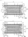
- the solid-state battery according to the present invention has, for example, a layered structure (particularly a stacked structure) as denoted by reference numerals "200A", “200B", “200C”, “200D”, “200E”, and “200F” (hereinafter, simply referred to as "200A to 200F") in FIGS. 1A , 2 , 3 , 4 , 5 , and 6 , respectively.
- the solid-state battery 200A to 200F according to the present invention includes a battery element 100 and a protective layer 5 that covers upper and lower surfaces of the battery element 100.
- FIG. 1A is a schematic sectional view illustrating an example of the solid-state battery according to the present invention having a single battery structure in the battery element 100.
- FIG. 1A is a schematic sectional view illustrating an example of the solid-state battery according to the present invention having a single battery structure in the battery element 100.
- FIG. 2 is a schematic sectional view illustrating an example of the solid-state battery according to the present invention having a series multiple battery structure in the battery element 100.
- FIG. 3 is a schematic sectional view illustrating an example of the solid-state battery according to the present invention having a parallel multiple battery structure in the battery element 100.
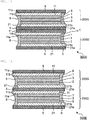
- FIG. 4 is a schematic sectional view illustrating another example of the solid-state battery according to the present invention having a single battery structure in the battery element 100.
- the solid-state battery of FIG. 4 has a structure similar to that of the solid-state battery of FIG.
- FIG. 5 is a schematic sectional view illustrating another example of the solid-state battery according to the present invention having the series multiple battery structure in the battery element 100.
- the solid-state battery of FIG. 5 has a structure similar to that of the solid-state battery of FIG. 2 except that the positive electrode layer 1 does not have the positive electrode current collecting layer 11 and has the electrical connection portion 1a, and the negative electrode layer 2 does not have the negative electrode current collecting layer 21 and has the electrical connection portion 2a.
- FIG. 6 is a schematic sectional view illustrating another example of the solid-state battery according to the present invention having the parallel multiple battery structure in the battery element 100.
- the solid-state battery of FIG. 6 has a structure similar to that of the solid-state battery of FIG. 3 except that the positive electrode layer 1 does not have the positive electrode current collecting layer 11 and has the electrical connection portion 1a, and the negative electrode layer 2 does not have the negative electrode current collecting layer 21 and has the electrical connection portion 2a.
- the battery element 100 is a main body part of the solid-state battery covered with the protective layer 5 and a side surface reinforcing portion 6, which will be described later, and includes one or more battery constitutional units 10.
- the battery constitutional unit 10 means a smallest constitutional unit capable of performing a battery function, and includes one positive electrode layer 1 and one negative electrode layer 2 facing each other, and one solid electrolyte layer 3 arranged between the positive electrode layer 1 and the negative electrode layer 2.
- the battery element 100 may have a single battery structure having only one battery constitutional unit 10, as illustrated in FIGS. 1A and 4 , for example. Further, for example, as illustrated in FIGS. 2, 3 , 5 and 6 , the battery element 100 may have a multiple battery structure having two or more battery constitutional units 10 stacked along the stacking direction L of each layer constituting each battery constitutional unit 10.
- the battery element 100 may have, as illustrated in FIGS. 2 and 5 for example, a series structure in which two or more battery constitutional units 10 (or respective layers constituting the battery constitutional units) are electrically arranged in series, or may have, as illustrated in FIGS. 3 and 6 for example, a parallel structure in which two or more battery constitutional units 10 (or respective layers constituting the battery constitutional units) are electrically arranged in parallel.
- all the layers constituting the battery element 100 be integrally sintered as sintered bodies together between two adjacent layers.
- the part that all the layers are integrally sintered as sintered bodies together between two adjacent layers means that the two adjacent layers are joined by sintering. Specifically, the two adjacent layers are both sintered bodies, but are integrally sintered. Note that the two adjacent layers do not have to be all strictly integrated, and a part of the layers may be not integrated. The two adjacent layers are only required to be integrated as a whole.
- the battery element 100 has one or more battery constitutional units 10 and the positive electrode layer 1 and the negative electrode layer 2 have the positive electrode current collecting layer 11 and the negative electrode current collecting layer 21, respectively, it is preferable that the positive electrode current collecting layer 11, the positive electrode layer 1, the solid electrolyte layer 3, the negative electrode layer 2, and the negative electrode current collecting layer 21 employ an integrally sintered structure in a predetermined stacking order.
- the positive electrode layer 1, the solid electrolyte layer 3, and the negative electrode layer 2 employ an integrally sintered structure in a predetermined stacking order.
- connection layer 7 be also joined to the adjacent layer by sintering, similarly to other layers.
- the positive electrode layer 1 and the negative electrode layer 2 may have the positive electrode current collecting layer 11 and the negative electrode current collecting layer 21, respectively, as illustrated in FIGS. 1A , 2 and 3 , or they do not need to have the positive electrode current collecting layer 11 and the negative electrode current collecting layer 21, respectively, as illustrated in FIGS. 4 to 6 .
- the positive electrode current collecting layer 11 and the negative electrode current collecting layer 21 are provided with electrical connection portions 11a and 21a, respectively, for electrical connection to the outside.
- the electrical connection portions 11a and 21a will be also referred to as electronic input and output portions for inputting and outputting electrons.
- the positive electrode layer 1 and the negative electrode layer 2 do not have the positive electrode current collecting layer 11 and the negative electrode current collecting layer 21, respectively, as illustrated in FIGS. 4 to 6 , the positive electrode layer 1 and the negative electrode layer 2 are provided with electrical connection portions 1a and 2a, respectively, for electrical connection to the outside.
- the electrical connection portions 1a and 2a will be also referred to as an electron input and output portion for inputting and outputting electrons.
- the solid-state batteries illustrated in FIGS. 2, 3 , 5 , and 6 include two battery constitutional units 10 in the battery element 100, but the number of battery constitutional units 10 included in one solid-state battery is not particularly limited, and for example, the number may be one or more and 100 or less, particularly one or more and 50 or less.
- the solid-state battery according to the present invention may have any shape in a plan view, and usually has a rectangular shape.
- the rectangular shape includes squares and rectangles.
- the positive electrode layer 1 is what is called a positive electrode active material layer, and may additionally have a positive electrode current collecting layer 11. When the positive electrode layer 1 has the positive electrode current collecting layer 11, the positive electrode layer 1 may be provided on one side of the positive electrode current collecting layer 11 or may be provided on both sides.
- the positive electrode layer 1 is constituted of a sintered body containing positive electrode active material particles, and may usually be constituted of a sintered body containing positive electrode active material particles, electron conductive material particles, and solid electrolyte particles contained in the solid electrolyte layer 3.
- the negative electrode layer 2 is what is called a negative electrode active material layer, and may additionally have a negative electrode current collecting layer 12. When the negative electrode layer 2 has the negative electrode current collecting layer 21, the negative electrode layer 2 may be provided on one side of the negative electrode current collecting layer 21 or may be provided on both sides.
- the negative electrode layer 2 is constituted of a sintered body containing negative electrode active material particles, and may usually be constituted of a sintered body containing negative electrode active material particles, the electron conductive material particles, and the solid electrolyte particles contained in the solid electrolyte layer 3.
- the positive electrode active material contained in the positive electrode layer and the negative electrode active material contained in the negative electrode layer are substances involved in exchange of electrons in the solid-state battery, and ions contained in a solid electrolyte material constituting the solid electrolyte layer move (being conducted) between the positive electrode and the negative electrode and exchange electrons, thereby performing charging and discharging.
- the positive electrode layer and the negative electrode layer are particularly preferably layers capable of occluding and releasing lithium ions. That is, the solid-state battery according to the present invention is preferably a solid-state secondary battery in which lithium ions move between the positive electrode and the negative electrode through the solid electrolyte layer to charge and discharge the battery.
- the positive electrode active material contained in the positive electrode layer is not particularly limited, and for example, at least one selected from the group consisting of a lithium-containing phosphoric acid compound having a nasicon -type structure, a lithium-containing phosphoric acid compound having an olivine-type structure, a lithium-containing layered oxide, and a lithium-containing oxide having a spinel-type structure, and the like may be mentioned.
- An example of the lithium-containing phosphoric acid compound having a nasicon-type structure is Li 3 V 2 (PO 4 ) 3 or the like.
- Examples of the lithium-containing phosphoric acid compound having an olivine-type structure include Li 3 Fe 2 (PO 4 ) 3 , LiMnPO 4 , and the like.
- lithium-containing layered oxide examples include LiCoO 2 , LiCO 1/3 Ni 1/3 Mn 1/3 O 2 , and the like.
- lithium-containing oxide having a spinel-type structure examples include LiMn 2 O 4 , LiNi 0.5 Mn 1.5 O 4 , and the like.
- the negative electrode active material contained in the negative electrode layer is not particularly limited, and for example, at least one selected from the group consisting of an oxide containing at least one element selected from the group consisting of Ti, Si, Sn, Cr, Fe, Nb, and Mo, a graphite-lithium compound, a lithium alloy, a lithium-containing phosphoric acid compound having a nasicon-type structure, a lithium-containing phosphoric acid compound having an olivine-type structure, and a lithium-containing oxide having a spinel-type structure and the like may be mentioned.
- An example of the lithium alloy is Li-Al and the like.
- lithium-containing phosphoric acid compound having a nasicon-type structure is Li 3 V 2 (PO 4 ) 3 or the like.
- An example of the lithium-containing phosphoric acid compound having an olivine-type structure is Li 3 Fe 2 (PO 4 ) 3 , and the like.
- An example of the lithium-containing oxide having a spinel-type structure is Li 4 Ti 5 O 12 , and the like.
- the electron conductive material contained in the positive electrode layer and the negative electrode layer is not particularly limited, and examples thereof include metal materials such as silver, palladium, gold, platinum, aluminum, copper, and nickel, and carbon materials.
- metal materials such as silver, palladium, gold, platinum, aluminum, copper, and nickel, and carbon materials.
- carbon is preferable because it does not easily react with the positive electrode active material, the negative electrode active material, and the solid electrolyte material, and is effective in reducing internal resistance of the solid-state battery.
- the solid electrolyte material contained in the positive electrode layer and the negative electrode layer may be selected from, for example, materials similar to solid electrolyte materials that can be contained in the solid electrolyte layer that will be described later.
- the positive electrode layer and the negative electrode layer may each independently contain a sintering additive.
- the sintering additive is not particularly limited, and can be, for example, at least one selected from the group consisting of lithium oxide, sodium oxide, potassium oxide, boron oxide, silicon oxide, bismuth oxide, and phosphorus oxide.
- the positive electrode layer 1 and the negative electrode layer 2 do not have the positive electrode current collecting layer 11 and the negative electrode current collecting layer 21, which will be described later, respectively, as illustrated in FIGS. 4 to 6
- the positive electrode layer 1 and the negative electrode layer 2 have electrical connection portions 1a and 2a, respectively, for electrical connection to the outside and are configured to be electrically connectable to terminals.
- the electrical connection portions 1a and 2a have exposed portions 1b and 2b that are not covered with the protective layer 5 or the side surface reinforcing portion 6, which will be described later, and are usually provided at ends of the positive electrode layer 1 and the negative electrode layer 2, respectively.
- the thicknesses of the positive electrode layer and the negative electrode layer are not particularly limited, and may each be, for example, 2 ⁇ m or more and 50 ⁇ m or less, particularly 5 ⁇ m or more and 30 ⁇ m or less, independently of each other.
- the positive electrode layer 1 and the negative electrode layer 2 may have the positive electrode current collecting layer 11 and the negative electrode current collecting layer 21, respectively, on opposite sides of the solid electrolyte layer 3.
- the positive electrode current collecting layer 11 and the negative electrode current collecting layer 21 have electrical connection portions 11a and 21a, respectively, for electrical connection to the outside, and are configured to be electrically connectable to terminals.
- the electrical connection portions 11a and 21a have exposed portions 11b and 21b that are not covered with the protective layer 5 or the side surface reinforcing portions 6, which will be described later, and are usually provided at ends of the positive electrode current collecting layer 11 and the negative electrode current collecting layer 21, respectively.
- the positive electrode current collecting layer 11 and the negative electrode current collecting layer 21 may each have a foil form, but from the viewpoint of reducing manufacturing cost of the solid-state battery by integral firing and reducing internal resistance of the solid-state battery, it is preferable to have the form of a sintered body.
- the positive electrode current collecting layer 11 and the negative electrode current collecting layer 21 have the form of a sintered body, they may be constituted of, for example, a sintered body containing electron conductive material particles and a sintering additive.
- the electron conductive material contained in the positive electrode current collecting layer 11 and the negative electrode current collecting layer 21 may be selected from, for example, materials similar to the electron conductive material that can be contained in the positive electrode layer and the negative electrode layer.
- the sintering additive contained in the positive electrode current collecting layer 11 and the negative electrode current collecting layer 21 may be selected from, for example, materials similar to the sintering additive that can be contained in the positive electrode layer and the negative electrode layer.
- the thicknesses of the positive electrode current collecting layer and the negative electrode current collecting layer are not particularly limited, and may each be, for example, 1 ⁇ m or more and 5 ⁇ m or less, particularly 1 ⁇ m or more and 3 ⁇ m or less, independently of each other.
- the solid electrolyte layer 3 is constituted of a sintered body containing solid electrolyte particles.
- the material of the solid electrolyte particles (that is, the solid electrolyte material) is not particularly limited as long as it can provide ions that can move between the positive electrode layer and the negative electrode layer.
- the solid electrolyte material include a lithium-containing phosphoric acid compound having a nasicon structure, an oxide having a perovskite structure, an oxide having a garnet type or a garnet type similar structure, and the like.
- Li x M y (PO 4 ) 3 may be mentioned (where 1 ⁇ x ⁇ 2, 1 ⁇ y ⁇ 2, and M is at least one selected from the group consisting of Ti, Ge, Al, Ga, and Zr).
- An example of the lithium-containing phosphoric acid compound having a nasicon structure is Li 1.2 Al 0.2 Ti 1.8 (PO 4 ) 3 , or the like.
- An example of the oxide having a perovskite structure is La 0.55 Li 0.35 TiO 3 or the like.
- An example of the oxide having a garnet type or a garnet type similar structure is Li 7 La 3 Zr 2 O 12 or the like.
- the solid electrolyte layer may contain a sintering additive.
- the sintering additive contained in the solid electrolyte layer may be selected from, for example, materials similar to the sintering additive that can be contained in the positive electrode layer and the negative electrode layer.
- the thickness of the solid electrolyte layer is not particularly limited, and may be, for example, 1 ⁇ m or more and 15 ⁇ m or less, particularly 1 ⁇ m or more and 5 ⁇ m or less.
- the protective layer 5 is formed on the upper and lower surfaces of the battery element 100 in the solid-state battery, and is for electrically, physically, and chemically protecting the battery element 100.
- the protective layer 5 includes an insulating substance other than resin.
- the Insulating substance means a material that does not have ionic conductivity or electronic conductivity. Therefore, the insulating substance other than resin is an insulating inorganic substance having neither ionic conductivity nor electron conductivity.
- the inorganic substance having no ionic conductivity means an inorganic substance having ionic conductivity of 1 ⁇ 10 -7 S/cm or less.
- the ionic conductivity is preferably 1 ⁇ 10 -12 S/cm or less.
- the ionic conductivity of the inorganic substance having no ionic conductivity is usually 1 ⁇ 10 -18 S/cm or more.
- the inorganic substance having no electron conductivity means an inorganic substance having electron conductivity of 1 ⁇ 10 -7 S/cm or less.
- the electron conductivity is preferably 1 ⁇ 10 -12 S/cm or less.
- the electron conductivity of an inorganic substance having no electron conductivity is usually 1 ⁇ 10 -18 S/cm or more.
- the protective layer 5 includes such an insulating substance other than resin, the protective layer 5 has even more excellent moisture resistance, environmental resistance, and durability.
- the protective layer 5 can be made as a protective layer that is difficult to adsorb, absorb and allow permeation of moisture and gas (carbon dioxide) and has high joint strength with a battery element compared to a protective layer containing resin (for example, a polymer compound). Consequently, in the solid-state battery according to the present invention, the protective layer 5 is less likely to crack and fall off based on expansion due to adsorption and absorption of water and gas (carbon dioxide) and is less likely to fall off due to vibration, impact, and the like as compared to the protective layer containing a polymer compound.
- the protective layer 5 is less likely to allow permeation of moisture and gas (carbon dioxide) as compared to the protective layer containing a polymer compound. Consequently, the solid-state battery according to the present invention can further suppress deterioration of battery performance.
- the positive electrode layer, the negative electrode layer, and the solid electrolyte layer have ionic conductivity and conduct lithium or sodium, but the battery performance tends to deteriorate due to adsorption and absorption of water and gas (carbon dioxide).
- the protective layer containing resin for example, a polymer compound
- the protective layer easily adsorbs and absorbs water and gas (carbon dioxide), a crack and falling off based on expansion of the protective layer are likely to occur, and falling off due to vibration, impact, and the like is also likely to occur. If a crack and/or falling off occurs in the protective layer, the positive electrode layer, the negative electrode layer, and the solid electrolyte layer adsorb and absorb water and gas (carbon dioxide). Further, if the protective layer easily allows permeation of moisture and gas (carbon dioxide), the moisture and gas (carbon dioxide) invade the inside of the battery element, and the positive electrode layer, the negative electrode layer, and the solid electrolyte layer adsorb and absorb moisture and gas (carbon dioxide). Consequently, the battery performance deteriorates.
- water and gas carbon dioxide
- Examples of the insulating substance other than the resin constituting the protective layer 5 include glass and ceramics.
- Examples of the glass include quartz glass (SiO 2 ), composite oxide-based glass that is a combination of SiO 2 and one selected from at least one of PbO, B 2 O 3 , MgO, ZnO, Bi 2 O 3 , Na 2 O, and Al 2 O 3 , and the like.
- Examples of ceramics include alumina, cordierite, mullite, steatite, and forsterite.
- the protective layer 5 may be constituted of one or more materials selected from the group consisting of these substances.
- the protective layer 5 may contain a material having electron conductivity (for example, metal) as long as the battery element 100 is not short-circuited.
- the content ratio of the electron conductive material may be, for example, 1% by volume or less. Because the protective layer 5 contains an electron conductive material (for example, metal), the heat generated by battery reaction can be smoothly released to the outside.
- the protective layer 5 is constituted of a sintered body containing insulating substance particles other than the above-described resin.
- the sintered body constituting the protective layer 5 in the present invention has pores among the insulating substance particles, but also has density to an extent that allows suppressing adsorption, absorption, and permeation of moisture and gas (carbon dioxide) in its thickness direction (for example, the stacking direction L).
- the protective layer 5 It is not strictly unacceptable for the protective layer 5 to contain resin such as a polymer compound, and the polymer compound used in the production and/or a thermal decomposition product thereof may remain.
- the content of residues of the polymer compound and the thermal decomposition product thereof, and the like in the protective layer is usually 0.1% by weight or less, particularly 0.01% by weight or less with respect to the total amount of the protective layer. Note that also in the positive electrode layer, the positive electrode current collecting layer, the negative electrode layer, the negative electrode current collecting layer, the solid electrolyte layer, and the side surface reinforcing portion, which will be described later, residues may remain as in the protective layer.
- the content of residues in each layer or each portion of the positive electrode layer, the positive electrode current collecting layer, the negative electrode layer, the negative electrode current collecting layer, the solid electrolyte layer, and the side surface reinforcing portion, as a value with respect to the total amount of each layer, may be within a range similar to the range of the content of residues in the protective layer.
- Porosity of the protective layer 5 may be, for example, 0.1% by volume or more and 20% by volume or less, particularly 1% by volume or more and 10% by volume or less.
- values measured by a weight porosity method, a calculated tomography method using CT scan, an immersion method, or the like are used.
- Oxygen permeability of the protective layer 5 in the thickness direction may be, for example, 10 -1 cc/m 2 /day/atmospheric pressure or less, particularly 10 -3 cc/m 2 /day/atmospheric pressure or less.
- H 2 O permeability in the thickness direction of the protective layer 5 may be, for example, 10 -2 g/m 2 /day or less, particularly 10 -4 g/m2/day or less.
- H 2 O permeability values measured at 25°C by a carrier gas method, a compression method, and a Ca corrosion method are used.
- a thickness of a thickest portion of the protective layer 5 is preferably 500 ⁇ m or less, more preferably 100 ⁇ m or less, still more preferably 50 ⁇ m or less, and most preferably 20 ⁇ m or less, from the viewpoint of further suppressing deterioration of the battery performance.
- the protective layer 5 preferably has an average thickness of 1 ⁇ m or more, more preferably 5 ⁇ m or more, from the viewpoint of further suppressing deterioration of the battery performance due to adsorption, absorption, permeation, and the like of moisture and gas (carbon dioxide).
- the maximum thickness and the average thickness for thicknesses at any 100 points are used, respectively.
- the protective layer 5 covers the upper and lower surfaces of the battery element 100.
- the protective layer 5 may be in direct contact with the upper and lower surfaces of the battery element 100 covered with the protective layer 5 as illustrated in FIGS. 1A and 2 to 6 , or may be in indirect contact thereto with another layer (for example, an inorganic layer or a metal layer) interposed therebetween.
- the part that the protective layer 5 is in direct contact with the upper and lower surfaces of the battery element means that the protective layer 5 is in direct contact with the upper and lower surfaces of the battery element without an interposition of the another layer, the resin layer, and the liquid electrolyte between the protective layer 5 and the battery element.
- the protective layer 5 is preferably in direct contact with the surface of the battery element 100 covered with the protective layer 5 for the following reasons (1) and (2): reason (1) the protective layer 5 is more difficult to fall off even when a strong vibration and/or impact is applied to the solid-state battery, and deterioration of the battery performance accompanying falling off of the protective layer is even more difficult to occur; and reason (2) the absence of other layers that do not exhibit a battery function reduces the volume of the solid-state battery and thus improves energy density of the battery.
- the protective layer 5 be integrally sintered as sintered bodies together with the upper and lower surfaces of the battery element 100 covered with the protective layer 5.
- the part that the protective layer 5 is integrally sintered as sintered bodies together with the upper and lower surfaces of the battery element 100 covered with the protective layer 5 means that the protective layer 5 is joined by sintering to the upper and lower surfaces of the battery element 100 covered with the protective layer 5.
- the protective layer 5 and the upper and lower surfaces of the battery element 100 covered with the protective layer 5 are both sintered bodies, but are integrally sintered.
- the protective layer 5 and the battery element 100 preferably have an integrally sintered structure.
- the protective layer 5 and the upper and lower surfaces of the battery element 100 covered with the protective layer 5 do not have to be all strictly integrated, and a part thereof may be not integrated.
- the protective layer 5 and the upper and lower surfaces of the battery element 100 covered with the protective layer 5 may be integrated as a whole.
- the upper and lower surfaces of the battery element 100 covered with the protective layer 5 are usually surfaces of outermost layers of the battery element 100.
- the outermost layers of the battery element 100 are an uppermost layer arranged at a top and a lowermost layer arranged at a bottom among the layers 100 constituting the battery element.
- the surfaces of the outermost layers are an upper surface of the uppermost layer and a lower surface of the lowermost layer.
- the outermost layers covered with the protective layer 5 are usually selected from the positive electrode current collecting layer 11 and the negative electrode current collecting layer 21.
- the outermost layers covered with the protective layer 5 are the positive electrode current collecting layer 11 as the uppermost layer and the negative electrode current collecting layer 21 as the lowermost layer.
- the outermost layers covered with the protective layer 5 is the positive electrode current collecting layer 11 as the uppermost layer and the positive electrode current collecting layer 11 as the lowermost layer.
- the outermost layers covered with the protective layer 5 are usually selected from the positive electrode layer 1 and the negative electrode layer 2.
- the outermost layers covered with the protective layer 5 are the positive electrode layer 1 as the uppermost layer and the negative electrode layer 2 as the lowermost layer.
- the outermost layers covered with the protective layer 5 are the positive electrode layer 1 as the uppermost layer and the positive electrode layer 1 as the lowermost layer.
- the protective layer 5 preferably protrudes more than the battery element 100 in sectional view.
- the part that the protective layer 5 protrudes more than the battery element 100 in sectional view means that the protective layer 5 (particularly an end thereof), as illustrated in FIGS. 1A and 2 to 6 , protrudes to an outside m2 in the in-plane direction M perpendicular to the stacking direction L in sectional view more than the battery element 100 (particularly its end).
- Such a protrusion of the protective layer 5 is usually formed across the entire peripheral end of the protective layer 5 in plan view, as illustrated in FIG. 1B .
- a portion protruding from the battery element 100 is referred to as a "protruding portion 51".
- FIG. 1B is a schematic plan view illustrating the solid-state battery according to the present invention illustrated in FIG. 1A .
- the battery element 100 illustrates an overlapping portion of each layer constituting the battery element 100 in plan view, and thus, for example, the electrical connection portions 11a and 21a of the positive electrode current collecting layer 11 and the negative electrode current collecting layer 21, respectively, are omitted.
- the in-plane direction M perpendicular to the stacking direction L means any direction in the plane perpendicular to the stacking direction L with respect to the solid-state battery.
- the outside m2 of such an in-plane direction M is the outside m2 when viewed from the solid-state battery in the in-plane direction M, and an opposite direction of the outer direction m2 is an inner direction m1. Since the protective layer 5 protrudes more than the battery element 100 in sectional view, if a volume expansion occurs in the battery element 100 outward in the in-plane direction M perpendicular to the stacking direction L of each layer constituting the battery constitutional unit 100, the volume expansion can be contained between the protruding portions 51 of the protective layer 5 on the upper and lower surfaces of the battery element 100. Therefore, contact and short circuit with the adjacent solid-state battery in the direction M can be sufficiently prevented.
- a protruding length of the protective layer 5 (that is, a protruding length of the protruding portion 51) n (including n1 and n2) (mm) is not particularly limited as long as the volume expansion can be contained and may be, for example, 0.00001 ⁇ N or more and 0.1 ⁇ N or less, particularly 0.0001 ⁇ N or more and 0.01 ⁇ N or less with respect to the total length N (including N1 and N2) (mm) in the protruding direction.
- the solid-state battery according to the present invention preferably has the side surface reinforcing portion 6 on the side surface of the battery element 100, that is, the side surface of the stack constituted of the layers constituting the battery element 100, as illustrated in FIGS. 1A and 2 to 6 .
- the solid-state batteries 200A to 200F according to the present invention preferably have, as illustrated in FIGS.
- the side surface reinforcing portion 6 that covers the side surface of the battery element 100 between the protruding portion 51 (upper surface protruding portion) of the protective layer 5 covering the upper surface of the battery element 100 and the protruding portion 51 (lower surface protruding portion) of the protective layer 5 covering the lower surface of the battery element 100.
- the side surface reinforcing portion 6 covers the side surface of the battery element 100 from the upper surface (that is, the height of the upper surface) to the lower surface (that is, the height of the lower surface) of the battery element.
- the side surface of the battery element 100 includes not only a right side surface and a left side surface of the battery element but also a front side surface and a back side surface with respect to the paper surface.
- the side surface reinforcing portion 6 may be constituted of a sintered body containing solid electrolyte particles, may be constituted of a sintered body containing insulating substance particles other than resin, or may be a sintered body containing mixed particles thereof. Because the side surface reinforcing portion 6 is constituted of such a sintered body, the side surface reinforcing portion 6 has even more excellent moisture resistance, environmental resistance, and durability. Specifically, the side surface reinforcing portion 6 can be a side surface reinforcing portion 6 that is relatively difficult to adsorb, absorb, and allow permeation of moisture and gas (carbon dioxide), and has high joint strength with the battery element.
- the side surface reinforcing portion 6 is relatively less likely to crack and fall off based on expansion due to adsorption and absorption of water and gas (carbon dioxide), and is less likely to fall off due to vibration, impact, and the like. Further, the side surface reinforcing portion 6 is relatively difficult to allow permeation of moisture and gas (carbon dioxide). Consequently, the solid-state battery according to the present invention can further suppress deterioration of the battery performance. From the viewpoint of further suppressing deterioration of the battery performance of such a solid-state battery, it is preferable that the side surface reinforcing portion 6 be constituted of a sintered body containing insulating substance particles other than resin.
- the insulating substance other than resin that can form the side surface reinforcing portion 6 may be independently selected from materials similar to the insulating substance other than resin that can be contained in the protective layer.
- the thickness of the side surface reinforcing portion 6 is not particularly limited, and when the protective layer 5 has the protruding portion 51, it is equal to or less than the protruding length of the protruding portion 51.
- the thickness of the side surface reinforcing portion 6 is preferably, for example, 5 ⁇ m or more and 300 ⁇ m or less, particularly 5 ⁇ m or more and 100 ⁇ m or less, from the viewpoint of further suppressing deterioration of the battery performance due to adsorption, absorption, permeation, and the like of moisture and gas (carbon dioxide). Note that the thickness of the side surface reinforcing portion 6 is a thickness in the in-plane direction M perpendicular to the stacking direction L.
- the side surface reinforcing portion 6 be integrally sintered as sintered bodies together with the side surface of the battery element 100.
- the part that the side surface reinforcing portion 6 is integrally sintered as sintered bodies together with the side surface of the battery element 100 means that the side surface reinforcing portion 6 is joined by sintering to the side surface of the battery element 100.
- the side surface reinforcing portion 6 and the side surface of the battery element 100 are both sintered bodies, but are integrally sintered.
- the side surface reinforcing portion 6 and the battery element 100 have an integrally sintered structure.
- side surface reinforcing portion 6 and the side surface of the battery element 100 covered with the side surface reinforcing portion 6 do not have to be all strictly integrated, and a part thereof may be not integrated.
- the side surface reinforcing portion 6 and the side surface of the battery element 100 covered with the side surface reinforcing portion 6 are only required to be integrated as a whole.
- an outer peripheral surface 61 of the side surface reinforcing portion 6 is preferably curved inward m1 in the in-plane direction M perpendicular to the stacking direction L.
- Being curved means being continuously bent or gradually depressed.
- the part that the outer peripheral surface 61 of the side surface reinforcing portion 6 is curved inward m1 in the in-plane direction M perpendicular to the stacking direction L in sectional view means that, as illustrated in FIGS. 7 to 11 , the outer peripheral surface 61 of the side surface reinforcing portion 6 gradually approaches the side surface of the battery element 100 as it advances upward in the stacking direction L, and then gradually moves away from the side surface.
- FIG. 7 is a schematic sectional view illustrating another example of the solid-state battery according to the present invention having the single battery structure in the battery element.
- the solid-state battery of FIG. 7 is similar to the solid-state battery of FIG. 1A except that the side surface reinforcing portion 6 has a curve on the outer peripheral surface 61.
- FIG. 8 is a schematic sectional view illustrating another example of the solid-state battery according to the present invention having the series multiple battery structure in the battery element.
- the solid-state battery of FIG. 8 is similar to the solid-state battery of FIG. 2 except that the side surface reinforcing portion 6 has a curve on the outer peripheral surface 61.
- FIGS. 9 and 10 are schematic sectional views illustrating another example of the solid-state battery according to the present invention having a parallel multiple battery structure in the battery element.
- the solid-state batteries of FIGS. 9 and 10 are similar to the solid-state batteries of FIG. 3 except that the side surface reinforcing portion 6 has a curve on the outer peripheral surface 61.
- FIG. 11 is a schematic sectional view illustrating another example of the solid-state battery according to the present invention having the parallel multiple battery structure in the battery element. Note that the solid-state battery of FIG. 11 has a parallel multiple battery structure including four battery constitutional units 10.
- the curve of the outer peripheral surface 61 of the side surface reinforcing portion 6 may be formed over the entire circumference of the side surface reinforcing portion 6 in plan view.
- the depth of the curve is not particularly limited as long as the shape of the solid-state battery can be maintained.
- a maximum depth d of the curve is usually 0.01 ⁇ n or more and 0.8 ⁇ n or less, particularly 0.1 ⁇ n or more and 0.5 ⁇ n or less, with respect to the protrusion length n (mm) of the protruding portion 51.
- the maximum depth d of the curve may be, for example, 50 ⁇ m or less, particularly 1 ⁇ m or more and 50 ⁇ m or more.
- the number of curves per one side in the in-plane direction M perpendicular to the stacking direction L in sectional view may be one or more (for example, one or more and three or less) depending on a volume change (for example, a volume change due to sintering) of each layer constituting the battery element 100.
- One side means one side in a left-right direction in sectional view.
- the number of curves per one side in the left-right direction in the sectional view may be one. Further, for example, as in the solid-state battery illustrated in FIG.
- the number of curves on the left side in the sectional view may be one, and the number of curves on the right side may be two.
- the reason why the number of curves on the right side of the solid-state battery illustrated in FIG. 9 is two is that, for example, the degree of volume shrinkage of the negative electrode current collecting layer 21 at the time of sintering is smaller than that of the other layers.
- the side surface reinforcing portion 6 preferably has porosity within a range similar to that of the porosity of the protective layer 5.
- the side surface reinforcing portion 6 preferably has air permeability in the thickness direction within a range similar to that of the air permeability in the thickness direction of the protective layer 5.
- At least a part of the electrical connection portions 11a, 21a, 1a, and 2a is not covered with the protective layer 5 or the side surface reinforcing portion 6, and an exposed portion is provided in the electrical connection portions.
- the positive electrode layer 1 and the negative electrode layer 2 have the positive electrode current collecting layer 11 and the negative electrode current collecting layer 21, respectively, at least a part of the electrical connection portions 11a and 21a of the positive electrode current collecting layer 11 and the negative electrode current collecting layer 21, respectively, is not covered with the protective layer 5 or the side surface reinforcing portion 6, and the exposed portions 11b and 21b are provided in the electrical connection portions.
- the exposed portions 11b and 21b mean portions where the positive electrode current collecting layer 11 and the negative electrode current collecting layer 21 are exposed, respectively.
- the positive electrode layer 1, the positive electrode current collecting layer 11, the negative electrode layer 2, the negative electrode current collecting layer 21, and the solid electrolyte layer 3 constituting the battery element 100 are not exposed to the outside of the protective layer 5 or the side surface reinforcing portion 6 except the exposed portions 11b and 21b. In other words, it is preferable that the entire surface of the outer surface of the battery element 100 except the exposed portions 11b and 21b be covered with the protective layer 5 or the side surface reinforcing portion 6.
- all the exposed portions 11b and 21b are formed on the side surfaces of the battery element 100 (or solid-state battery), but are not limited thereto.
- the exposed portions 11b and 21b of the electrical connection portions 11a and 21a in the positive electrode current collecting layer 11 and the negative electrode current collecting layer 21 as the outermost layers, respectively, may be provided on the upper surface or the lower surface of the battery element 100 (or the solid-state battery).
- the positive electrode layer 1 and the negative electrode layer 2 do not have the positive electrode current collecting layer and the negative electrode current collecting layer, respectively, at least a part of the electrical connection portions 1a and 2a of the positive electrode layer 1 and the negative electrode layer 2 is not covered with the protective layer 5 or the side surface reinforcing portion 6, and the exposed portions 1b and 2b are provided in these electrical connection portions.
- the exposed portions 1b and 2b mean portions where the positive electrode layer 1 and the negative electrode layer 2 are exposed, respectively.
- the positive electrode layer 1, the negative electrode layer 2, and the solid electrolyte layer 3 constituting the battery element 100 are not exposed to the outside of the protective layer 5 or the side surface reinforcing portion 6 except the exposed portions 1b and 2b.
- the entire surface of the outer surface of the battery element 100 except the exposed portions 1b and 2b be covered with the protective layer 5 or the side surface reinforcing portion 6.
- all the exposed portions 1b and 2b are formed on the side surfaces of the battery element 100 (or solid-state battery), but are not limited thereto.
- the exposed portions 1b and 2b of the electrical connection portions 1a and 2a in the positive electrode layer 1 and the negative electrode layer 2 as the outermost layers, respectively, may be provided on the upper surface or the lower surface of the battery element 100 (or the solid-state battery).
- the solid-state batteries 200B, 200E may have the connection layer 7 between the battery constitutional units 10.
- the connection layer 7 achieves the connection between the positive electrode layer 1 and the negative electrode layer 2 and prevents an electrical short circuit between them.
- connection layer 7 may be constituted of a sintered body containing insulating substance particles other than resin.
- the insulating substance other than resin that can form the connection layer 7 may be independently selected from materials similar to the insulating substance other than resin that can be contained in the protective layer.
- the thickness of the connection layer 7 is not particularly limited, and is preferably 1 ⁇ m or more and 10 ⁇ m or less, particularly 1 ⁇ m or more and 3 ⁇ m or less, for example.
- connection layer 7 be integrally sintered as sintered bodies together with the adjacent layers (for example, the positive electrode layer 1 and/or the negative electrode layer 2).
- the part that the connection layer 7 is integrally sintered as sintered bodies together with the adjacent layer means that the connection layer 7 is joined by sintering to the adjacent layer.
- the connection layer 7 and the adjacent layers are both sintered bodies, but are integrally sintered.
- the connection layer 7 have a structure integrally sintered with all other layers constituting the battery element 100. Note that the connection layer 7 and the adjacent layers do not have to be all strictly integrated, and a part thereof may be not integrated.
- the connection layer 7 and the adjacent layers are only required to be integrated as a whole.
- a solid-state battery group according to the present invention includes two or more solid-state batteries. It is preferable that the solid-state battery group according to the present invention include one or more solid-state batteries according to the present invention described above, and include only two or more solid-state batteries according to the present invention from the viewpoint of further suppressing deterioration of the battery performance in a longer period of time. That is, it is preferable that the solid-state battery group according to the present invention be constituted of only two or more solid-state batteries according to the present invention.
- the two or more solid-state batteries according to the present invention may be independently selected from the group constituted of the above-described solid-state batteries according to the present invention.
- at least one factor selected from the following group may be different from each other, or all of these factors may be the same:
- all the solid-state batteries constituting the solid-state battery group according to the present invention have the same (or common) battery constitutional unit 10 from the viewpoint of further suppressing deterioration of the battery performance in a longer period of time on the basis of uniformization of the battery reaction.
- the part that all the solid-state batteries have the same (or common) battery constitutional unit 10 means that types and dimensions of constituent materials of the positive electrode layer 1 (and the positive electrode current collecting layer 11), the negative electrode layer 2 (and the negative electrode current collecting layer 21), and the solid electrolyte layer in the all solid-state batteries are the same.
- all of the above-described factors only include two or more same solid-state batteries according to the present invention, or at least one factor selected from the following group only include two or more solid-state batteries according to the present invention different from each other.
- the centers of gravity of the batteries can be controlled to suppress falling off from the substrate or the like, thereby suppressing deterioration of the battery performance for a much longer period of time.
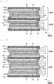
- a solid-state battery group 500A of FIG. 12 includes only two solid-state batteries according to the present invention, an upper solid-state battery corresponds to a solid-state battery 200G of FIG. 7 , and a lower solid-state battery corresponds to a solid-state battery 200G' having two protective layers 5' that have different constituent materials from those of the protective layer 5 of the upper solid-state battery 200G.
- FIG. 12 illustrates a schematic sectional view of a solid-state battery group according to a first embodiment of the present invention. Note that the protective layer 5' indicates that constituent materials actually used are different from those of the protective layer 5, and are included in the protective layer 5 described above.
- the two solid-state batteries have a single battery structure and are connected so as to form a parallel connection.
- capacity of the solid-state battery group 500A can be increased without changing the battery voltage as compared to one solid-state battery having the single battery structure.
- the number of solid-state batteries included in the solid-state battery group according to the present invention is not particularly limited, and may be, for example, two or more, particularly two or more and 100 or less, preferably two or more and 50 or less.
- the connection of two or more solid-state batteries constituting the solid-state battery group is based on parallel connection in FIG. 12 , but may be based on series connection.
- the solid-state battery group it is preferable that two adjacent solid-state batteries be integrally sintered as sintered bodies together with the protective layer interposed therebetween, and it is more preferable that all two adjacent solid-state batteries be integrally sintered as sintered bodies together with the protective layer interposed therebetween, among the two or more (preferably all) solid-state batteries constituting the solid-state battery group.
- the solid-state battery group even when a strong vibration or impact is applied to the solid-state battery group, it is difficult for the solid-state batteries to separate from each other, and it is difficult for the battery performance to deteriorate due to separation. Furthermore, deterioration of the battery performance can be further suppressed as compared to a case where the protective layer is not interposed between the two adjacent solid-state batteries.
- the part that two adjacent solid-state batteries are integrally sintered as sintered bodies together with the protective layer interposed therebetween means that the two adjacent solid-state batteries are joined by sintering with the protective layer interposed therebetween.
- the two adjacent solid-state batteries are both sintered bodies, but are integrally sintered.
- the protective layer and the battery element are integrally sintered as sintered bodies together in each solid-state battery, the protective layer of one solid-state battery and the protective layer of the other solid-state battery are integrally sintered (joined) as sintered bodies together.
- all the solid-state batteries constituting the solid-state battery group may be stacked along the stacking direction L of each layer constituting each battery constitutional unit as illustrated in FIG. 12 .
- At least a part of the solid-state batteries constituting the solid-state battery group according to the present invention may be arranged in the direction M perpendicular to the stacking direction L. Joining of sintered bodies together with the protective layer interposed therebetween can be achieved both between the two solid-state batteries adjacent to each other in the stacking direction L and between the two solid-state batteries adjacent to each other in the direction M perpendicular to the stacking direction L.
- two protective layers that is, a protective layer of one solid-state battery and a protective layer of the other solid-state battery
- two protective layers are interposed between two adjacent solid-state batteries, but it is also possible to unify the two protective layers and share one protective layer by the two solid-state batteries.
- only one protective layer may be interposed between the two adjacent solid-state batteries.
- only one protective layer may also be interposed between two other adjacent solid-state batteries.
- energy density of the solid-state battery group can be further improved by unifying the two protective layers between the two adjacent solid-state batteries.
- the form of the interposed protective layers is referred to as "two-layer form”.
- the form of the interposed protective layer is referred to as "single form”.
- FIG. 13 illustrates a schematic sectional view of a solid-state battery group according to a second embodiment of the present invention.
- the two solid-state batteries have a single battery structure and are connected so as to form a parallel connection.
- capacity of the solid-state battery group 500B can be increased without changing the battery voltage as compared to one solid-state battery having the single battery structure.
- FIG. 14 illustrates a schematic sectional view of a solid-state battery group according to a third embodiment of the present invention.
- the two solid-state batteries have a single battery structure and are connected so as to form a parallel connection.
- capacity of the solid-state battery group 500C can be increased without changing the battery voltage as compared to one solid-state battery having the single battery structure.
- FIG. 15 illustrates a schematic sectional view of a solid-state battery group according to a fourth embodiment of the present invention.
- two solid-state batteries are a solid-state battery having a single battery structure and a solid-state battery having a parallel multiple battery structure, and are connected so as to form a parallel connection.
- capacity of the solid-state battery group 500D can be increased without changing the battery voltage as compared to one of the above-described solid-state batteries.
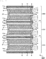
- FIG. 16 illustrates a schematic sectional view of a solid-state battery group according to a fifth embodiment of the present invention.
- the two solid-state batteries are solid-state batteries having a parallel multiple battery structure and are connected so as to form a parallel connection.
- capacity of the solid-state battery group 500E can be increased without changing the battery voltage as compared to one solid-state battery having the parallel multiple battery structure.
- FIG. 17 illustrates a schematic sectional view of a solid-state battery group according to a sixth embodiment of the present invention.
- the three solid-state batteries are solid-state batteries having a parallel multiple battery structure and are connected so as to form a parallel connection.
- capacity of the solid-state battery group 500F can be increased without changing the battery voltage as compared to one solid-state battery having the parallel multiple battery structure or one solid-state battery group 500E of FIG. 16 .
- FIG. 18 illustrates a schematic sectional view of a solid-state battery group according to a seventh embodiment of the present invention. Note that in each solid-state battery 2001' in FIG. 18 , the negative electrode layer 2 is illustrated as one layer for convenience. In FIG.
- the four solid-state batteries are solid-state batteries having a parallel multiple battery structure and are connected so as to form a parallel connection.
- capacity of the solid-state battery group 500G can be increased without changing the battery voltage as compared to one solid-state battery having the parallel multiple battery structure.
- FIG. 19 illustrates a schematic sectional view of a solid-state battery group according to an eighth embodiment of the present invention.
- the two solid-state batteries are solid-state batteries having a parallel multiple battery structure and are connected so as to form a parallel connection.
- capacity of the solid-state battery group 500H can be increased without changing the battery voltage as compared to one solid-state battery having the parallel multiple battery structure.
- FIG. 20 illustrates a schematic sectional view of a solid-state battery group according to a ninth embodiment of the present invention.
- two adjacent solid-state batteries have a series structure and are connected so as to form a parallel connection.
- such two adjacent solid-state batteries can be arranged so that the stacking order of the positive electrode layer, the negative electrode layer, the solid electrolyte layer, and the like is aligned with each other.
- the part that the stacking order is aligned with each other means that the stacking order is the same in two adjacent solid-state batteries.
- electrodes on both upper and lower sides of the protective layer 5 between the solid-state batteries can be set to different electrodes (the upper side of the protective layer 5 is a negative electrode (2, 21) and the lower side thereof is a positive electrode (1, 11) in FIG. 20 ). Therefore, the solid-state battery group 5001 can mutually absorb volume expansion and contraction during charging and discharging on both sides of the protective layer 5, and can further suppress deterioration of the battery.
- a solid-state battery group 500J of FIG. 21 includes only two solid-state batteries according to the present invention, and the two solid-state batteries both correspond to the solid-state battery 200H, the lower solid-state battery 200H' is installed vertically inversely in the stacking direction L with respect to the upper solid-state battery 200H, and the protective layers are unified between two adjacent solid-state batteries.
- two adjacent solid-state batteries have a series structure and are connected so as to form a parallel connection.
- such two adjacent solid-state batteries can be arranged so that the stacking order of the positive electrode layer, the negative electrode layer, the solid electrolyte layer, and the like is reversed from each other.
- the part that the stacking order is reversed from each other means that the stacking order is reversed in two adjacent solid-state batteries.
- electrodes on both the upper and lower sides of the protective layer 5 between the solid-state batteries can be set to the same electrodes (negative electrodes (2, 21) in FIG. 21 ). Therefore, in the solid-state battery group 500J, positions of the electrical connection portions (21a) are concentrated, it is possible to suppress intrusion of moisture and the like from the electrical connection portions into the battery element 100, and deterioration of the battery can be further suppressed. A risk of poor connection can be reduced when connecting to an external terminal in practice.
- the solid-state battery according to the present invention can be produced by a printing method such as a screen printing method, a green sheet method using a green sheet, or a composite method thereof.
- a printing method such as a screen printing method, a green sheet method using a green sheet, or a composite method thereof.
- a method for manufacturing a solid-state battery according to the present invention includes a step of forming an unfired stack by a printing method, and a step of firing the unfired stack.
- an unfired stack having a predetermined structure is formed on a substrate by a printing method.
- the curved portion paste is a paste for forming a layer that is burnt down by sintering, and forms a dent in the curved portion.
- the paste can be produced by wet-mixing a predetermined constituent material of each layer selected from the group consisting of a positive electrode active material, a negative electrode active material, an electron conductive material, a solid electrolyte material, an insulating substance, and a sintering additive with an organic vehicle obtained by dissolving an organic material in a solvent.
- the positive electrode layer paste contains a positive electrode active material, an electron conductive material, a solid electrolyte material, an organic material, and a solvent.
- the negative electrode layer paste contains a negative electrode active material, an electron conductive material, a solid electrolyte material, an organic material, and a solvent.
- the positive electrode current collecting layer paste and the negative electrode current collecting layer paste contain an electron conductive material, a sintering additive, an organic material, and a solvent.
- the solid electrolyte layer paste contains a solid electrolyte material, a sintering additive, an organic material, and a solvent.
- the protective layer paste contains an insulating substance, an organic material, and a solvent.
- the side surface reinforcing portion paste contains a solid electrolyte material (and/or an insulating substance), a sintering additive, an organic material, and a solvent.
- the curved portion paste contains an organic material and a solvent.
- connection layer paste contains a solid electrolyte material (and/or insulating substance), a sintering additive, an organic material, and a solvent.
- the organic materials contained in the pastes are not particularly limited, but polymer compounds such as polyvinyl acetal resin, cellulose resin, polyacrylic resin, polyurethane resin, polyvinyl acetate resin, and polyvinyl alcohol resin can be used.
- the solvent is not particularly limited as long as the organic material can be dissolved, and for example, toluene, ethanol, and the like can be used.
- a medium can be used, and specifically, a ball mill method, a viscomill method, or the like can be used.
- a wet mixing method that does not use media may be used, and a sand mill method, a high-pressure homogenizer method, a kneader dispersion method, or the like can be used.
- the substrate is not particularly limited as long as it can support the unfired stack, and for example, a polymer material such as polyethylene terephthalate can be used. Note that when the unfired stack is subjected to a firing step while being held on the substrate, the substrate used is one having heat resistance to firing temperature.
- print layers are sequentially stacked with predetermined thicknesses and pattern shapes, and an unfired stack corresponding to a predetermined solid-state battery structure is formed on the substrate.
- a drying treatment that is, a solvent evaporation treatment
- FIG. 22 is a flow chart of a step of forming an unfired stack for explaining an example of the method for manufacturing a solid-state battery according to the present invention. The substrate is omitted in FIG. 22 .
- a print layer made of the curved portion paste may be formed in the portion corresponding to a dent in the curved portion. In this case, by performing stacking by reducing the thickness of each print layer, it is possible to form a gradual increase or decrease in a curve depth.
- the unfired stack may be peeled off from the substrate and subjected to a firing step, or the unfired stack may be subjected to a firing step while being held on the substrate.
- the unfired stack is subjected to firing.
- the firing is carried out by removing the organic material in a nitrogen gas atmosphere containing oxygen gas, for example, at 500°C, and then heating in a nitrogen gas atmosphere, for example, at 550°C to 1000°C.
- the firing may usually be performed while pressurizing the unfired stack in the stacking direction L (in some cases, the stacking direction L and the direction M perpendicular to the stacking direction L).
- the pressing force is not particularly limited, and may be, for example, 1 kg/cm 2 or more and 1000 kg/cm 2 or less, particularly 5 kg/cm 2 or more and 500 kg/cm 2 or less.
- the solid-state battery group according to the present invention can be manufactured by a method similar to the above-described method for manufacturing the solid-state battery according to the present invention, except that an unfired stack corresponding to a structure of a predetermined solid-state battery group is formed in the step of forming the unfired stack.
- the solid-state battery group according to the present invention can be produced by forming the unfired stack corresponding to the structure of the predetermined solid-state battery group by dividing into two or more and using them in combination.
- the solid-state battery group 500A of FIG. 12 in the above-described step of forming the unfired stack, two unfired stacks of an unfired stack corresponding to a structure of the solid-state battery 200G and an unfired stack corresponding to a structure of the solid-state battery 200G' are individually formed.
- the two unfired stacks are then used in combination before being subjected to the firing step.
- the two unfired stacks are stacked or arranged and then assembled so as to correspond to the structure of the predetermined solid-state battery group.
- An obtained stack aggregate is subjected to the above-described firing step.
- the unfired stack corresponding to the structure of the predetermined solid-state battery group by dividing into two or more and using them in combination, not only the specifications (for example, battery capacity) of the solid-state battery group demanded by the user can be met easily, but also the solid-state battery group can be easily manufactured (or processed).
- a solid-state battery according to one embodiment of the present invention can be used in various fields where power storage is expected.
- the solid-state battery according to one embodiment of the present invention can be used, although merely examples, for electric, information, communication fields where mobile devices are used (for example, fields of mobile devices such as mobile phones, smartphones, smart watches, laptop computers and digital cameras, activity meters, arm computers, electronic paper, and the like), home and small industrial applications (for example, fields of power tools, golf carts, and domestic, nursing, and industrial robots), large industrial applications (for example, fields of forklifts, elevators, gantry cranes), transportation system fields (for example, fields of hybrid cars, electric cars, buses, trains, power assisted bicycles, electric motorcycle, and the like), power system applications (for example, fields of various power generations, road conditioners, smart grids, general household power storage systems, and the like), medical applications (medical equipment fields such as earphone hearing aids), pharmaceutical applications (fields such as dose management systems), and IoT fields, space and deep sea applications (for example, fields
Landscapes
- Chemical & Material Sciences (AREA)
- Chemical Kinetics & Catalysis (AREA)
- Electrochemistry (AREA)
- General Chemical & Material Sciences (AREA)
- Engineering & Computer Science (AREA)
- Manufacturing & Machinery (AREA)
- Inorganic Chemistry (AREA)
- Condensed Matter Physics & Semiconductors (AREA)
- General Physics & Mathematics (AREA)
- Physics & Mathematics (AREA)
- Materials Engineering (AREA)
- Secondary Cells (AREA)
- Sealing Battery Cases Or Jackets (AREA)
- Battery Mounting, Suspending (AREA)
- Connection Of Batteries Or Terminals (AREA)
Abstract
Description
- The present invention relates to a solid-state battery and a solid-state battery group.
- In recent years, demand for batteries as power sources for portable electronic devices such as mobile phones and portable personal computers has increased significantly. In batteries used for such purposes, an electrolyte (electrolytic solution) such as an organic solvent has been conventionally used as a medium for moving ions. However, in the battery having the above configuration, there is a risk that the electrolytic solution may leak out. Furthermore, the organic solvent and the like used in the electrolytic solution are flammable substances. Thus, it is required to improve safety for the battery.
- Accordingly, in order to improve safety for the battery, research on a solid-state battery using a solid electrolyte as the electrolyte instead of the electrolytic solution is in progress.
- For example,
Patent Documents 1 to 3 disclose a technique to form a protective layer containing a polymer compound on the outermost surface of a battery element having a positive electrode and a negative electrode and a solid electrolyte between them, so as to electrically and physically protect the solid-state battery. -
- Patent Document 1:
Japanese Patent Application Laid-Open No. 2008-186595 - Patent Document 2:
Japanese Patent Application Laid-Open No. 2006-351326 - Patent Document 3:
Japanese Patent Application Laid-Open No. 2016-001601 - However, the inventors of the present invention have found that when the solid-state battery has the protective layer containing the polymer compound on the surface of the battery element, the protective layer expands and cracks and/or falls off due to the polymer compound adsorbing water or gas, and thus the function as the protective layer is lost and battery performance deteriorates.
- The inventors of the present invention have also found that when the surface of the battery element in the solid-state battery is just covered with the protective film containing a polymer compound, the protective layer is likely to fall off due to strong vibration, impact, and the like on the battery, and thus the function as the protective layer will be lost and the battery performance will deteriorate.
- The inventors of the present invention have further found that when a plurality of conventional solid-state batteries is arranged adjacent to a vertical in-plane direction M perpendicular to a stacking direction L of a positive electrode layer, a negative electrode layer, and a solid electrolyte layer, a short circuit can occur between two adjacent solid-state batteries. Specifically, for example, as illustrated in
FIG. 23 , when a plurality of conventional solid-state batteries (800, 900) was arranged adjacent to each other in the in-plane direction M perpendicular to the stacking direction L,volume expansions state batteries state batteries - It is an object of the present invention to provide a solid-state battery having a protective layer that is less likely to adsorb water and gas and has high joint strength with a battery element as compared to a protective layer containing a polymer compound.
- It is also an object of the present invention to provide a solid-state battery having a protective layer that is less likely to adsorb water and gas and has high joint strength with a battery element as compared to a protective layer containing a polymer compound, and that is also capable of suppressing a short circuit due to volume expansion even if it is arranged adjacent in the in-plane direction M perpendicular to the stacking direction L of a positive electrode layer, a negative electrode layer, and a solid electrolyte layer.
- The present invention relates to a solid-state battery including a battery element that includes one or more battery constitutional units including a positive electrode layer and a negative electrode layer facing each other and a solid electrolyte layer arranged between the positive electrode layer and the negative electrode layer, and a protective layer that covers upper and lower surfaces of the battery element, in which the protective layer includes an insulating substance other than resin.
- A solid-state battery according to the present invention has a protective layer that is less likely to adsorb water and gas and has high joint strength with a battery element as compared to a protective layer containing a polymer compound. Consequently, in the solid-state battery according to the present invention, the protective layer is less likely to crack and fall off due to adsorption of water and gas, and is less likely to fall off due to vibration, impact, and the like as compared to the protective layer containing a polymer compound. Therefore, the solid-state battery according to the present invention can further suppress deterioration of battery performance.
-
-
FIG. 1A is a schematic sectional view illustrating an example of a solid-state battery according to the present invention having a single battery structure in a battery element. -
FIG. 1B is a schematic plan view of the solid-state battery according to the present invention illustrated inFIG. 1A . -
FIG. 2 is a schematic sectional view illustrating an example of the solid-state battery according to the present invention having a series multiple battery structure in the battery element. -
FIG. 3 is a schematic sectional view illustrating an example of the solid-state battery according to the present invention having a parallel multiple battery structure in the battery element. -
FIG. 4 is a schematic sectional view illustrating another example of the solid-state battery according to the present invention having the single battery structure in the battery element. -
FIG. 5 is a schematic sectional view illustrating another example of the solid-state battery according to the present invention having the series multiple battery structure in the battery element. -
FIG. 6 is a schematic sectional view illustrating another example of the solid-state battery according to the present invention having the parallel multiple battery structure in the battery element. -
FIG. 7 is a schematic sectional view illustrating another example of the solid-state battery according to the present invention having the single battery structure in the battery element. -
FIG. 8 is a schematic sectional view illustrating another example of the solid-state battery according to the present invention having the series multiple battery structure in the battery element. -
FIG. 9 is a schematic sectional view illustrating another example of the solid-state battery according to the present invention having the parallel multiple battery structure in the battery element. -
FIG. 10 is a schematic sectional view illustrating another example of the solid-state battery according to the present invention having the parallel multiple battery structure in the battery element. -
FIG. 11 is a schematic sectional view illustrating another example of the solid-state battery according to the present invention having the parallel multiple battery structure in the battery element. -
FIG. 12 illustrates a schematic sectional view of a solid-state battery group according to a first embodiment of the present invention. -
FIG. 13 illustrates a schematic sectional view of a solid-state battery group according to a second embodiment of the present invention. -
FIG. 14 illustrates a schematic sectional view of a solid-state battery group according to a third embodiment of the present invention. -
FIG. 15 illustrates a schematic sectional view of a solid-state battery group according to a fourth embodiment of the present invention. -
FIG. 16 illustrates a schematic sectional view of a solid-state battery group according to a fifth embodiment of the present invention. -
FIG. 17 illustrates a schematic sectional view of a solid-state battery group according to a sixth embodiment of the present invention. -
FIG. 18 illustrates a schematic sectional view of a solid-state battery group according to a seventh embodiment of the present invention. -
FIG. 19 illustrates a schematic sectional view of a solid-state battery group according to an eighth embodiment of the present invention. -
FIG. 20 illustrates a schematic sectional view of a solid-state battery group according to a ninth embodiment of the present invention. -
FIG. 21 illustrates a schematic sectional view of a solid-state battery group according to a tenth embodiment of the present invention. -
FIG. 22 is a flow chart for explaining an example of a step of forming an unfired stack in a method for manufacturing a solid-state battery according to the present invention. -
FIG. 23 is a schematic sectional view of a solid-state battery for explaining a mechanism of a short circuit caused by volume expansion, which is a problem in a conventional solid-state battery. - The present invention provides a solid-state battery. The term "solid-state battery" as used herein refers in a broad sense to a battery in which its components (particularly an electrolyte layer) are constituted of solids, and refers in a narrow sense to an "all-solid-state battery" in which its components (particularly all the components) are constituted of solids. The "solid-state battery" as used herein includes what is called a "secondary battery" capable of repeating charging and discharging, and a "primary battery" capable of discharging only. The "solid-state battery" is preferably the "secondary battery". The "secondary battery" is not overly limited by its name and may include, for example, a "power storage device" and the like.
- The term "plan view" as used herein refers to a state (top view or bottom view) in which an object is viewed from above or below along a thickness direction based on a stacking direction L of layers to be described later that constitute the solid-state battery. Further, the "sectional view" as used herein refers to a sectional state (sectional view) when viewed from a direction substantially perpendicular to the thickness direction based on the stacking direction L of the layers to be described later that constitute the solid-state battery. The "vertical direction" and "horizontal direction" as used directly or indirectly herein correspond to a vertical direction and a horizontal direction in the drawings, respectively. Unless otherwise specified, the same reference sign or symbol indicates the same member or part or the same meaning and content. In one preferred embodiment, it can be considered that a vertical downward direction (that is, the direction in which gravity acts) corresponds to a "downward direction" and the opposite direction corresponds to an "upward direction".
- The solid-state battery according to the present invention has, for example, a layered structure (particularly a stacked structure) as denoted by reference numerals "200A", "200B", "200C", "200D", "200E", and "200F" (hereinafter, simply referred to as "200A to 200F") in
FIGS. 1A ,2 ,3 ,4 ,5 , and6 , respectively. The solid-state battery 200A to 200F according to the present invention includes abattery element 100 and aprotective layer 5 that covers upper and lower surfaces of thebattery element 100.FIG. 1A is a schematic sectional view illustrating an example of the solid-state battery according to the present invention having a single battery structure in thebattery element 100.FIG. 2 is a schematic sectional view illustrating an example of the solid-state battery according to the present invention having a series multiple battery structure in thebattery element 100.FIG. 3 is a schematic sectional view illustrating an example of the solid-state battery according to the present invention having a parallel multiple battery structure in thebattery element 100.FIG. 4 is a schematic sectional view illustrating another example of the solid-state battery according to the present invention having a single battery structure in thebattery element 100. The solid-state battery ofFIG. 4 has a structure similar to that of the solid-state battery ofFIG. 1A except that apositive electrode layer 1 does not have a positive electrodecurrent collecting layer 11 and has anelectrical connection portion 1a, and anegative electrode layer 2 does not have a negative electrodecurrent collecting layer 21 and has anelectrical connection portion 2a.FIG. 5 is a schematic sectional view illustrating another example of the solid-state battery according to the present invention having the series multiple battery structure in thebattery element 100. The solid-state battery ofFIG. 5 has a structure similar to that of the solid-state battery ofFIG. 2 except that thepositive electrode layer 1 does not have the positive electrodecurrent collecting layer 11 and has theelectrical connection portion 1a, and thenegative electrode layer 2 does not have the negative electrodecurrent collecting layer 21 and has theelectrical connection portion 2a.FIG. 6 is a schematic sectional view illustrating another example of the solid-state battery according to the present invention having the parallel multiple battery structure in thebattery element 100. The solid-state battery ofFIG. 6 has a structure similar to that of the solid-state battery ofFIG. 3 except that thepositive electrode layer 1 does not have the positive electrodecurrent collecting layer 11 and has theelectrical connection portion 1a, and thenegative electrode layer 2 does not have the negative electrodecurrent collecting layer 21 and has theelectrical connection portion 2a. - The
battery element 100 is a main body part of the solid-state battery covered with theprotective layer 5 and a sidesurface reinforcing portion 6, which will be described later, and includes one or more batteryconstitutional units 10. The batteryconstitutional unit 10 means a smallest constitutional unit capable of performing a battery function, and includes onepositive electrode layer 1 and onenegative electrode layer 2 facing each other, and onesolid electrolyte layer 3 arranged between thepositive electrode layer 1 and thenegative electrode layer 2. - The
battery element 100 may have a single battery structure having only one batteryconstitutional unit 10, as illustrated inFIGS. 1A and4 , for example. Further, for example, as illustrated inFIGS. 2, 3 ,5 and6 , thebattery element 100 may have a multiple battery structure having two or more batteryconstitutional units 10 stacked along the stacking direction L of each layer constituting each batteryconstitutional unit 10. When having a multiple battery structure, thebattery element 100 may have, as illustrated inFIGS. 2 and5 for example, a series structure in which two or more battery constitutional units 10 (or respective layers constituting the battery constitutional units) are electrically arranged in series, or may have, as illustrated inFIGS. 3 and6 for example, a parallel structure in which two or more battery constitutional units 10 (or respective layers constituting the battery constitutional units) are electrically arranged in parallel. - From the viewpoint of suppressing deterioration of the battery in a longer period of time, it is preferable that all the layers constituting the
battery element 100 be integrally sintered as sintered bodies together between two adjacent layers. The part that all the layers are integrally sintered as sintered bodies together between two adjacent layers means that the two adjacent layers are joined by sintering. Specifically, the two adjacent layers are both sintered bodies, but are integrally sintered. Note that the two adjacent layers do not have to be all strictly integrated, and a part of the layers may be not integrated. The two adjacent layers are only required to be integrated as a whole. - For example, as illustrated in
FIGS. 1A ,2 and 3 , when thebattery element 100 has one or more batteryconstitutional units 10 and thepositive electrode layer 1 and thenegative electrode layer 2 have the positive electrodecurrent collecting layer 11 and the negative electrodecurrent collecting layer 21, respectively, it is preferable that the positive electrodecurrent collecting layer 11, thepositive electrode layer 1, thesolid electrolyte layer 3, thenegative electrode layer 2, and the negative electrodecurrent collecting layer 21 employ an integrally sintered structure in a predetermined stacking order. - Further, for example, as illustrated in
FIGS. 4 to 6 , when thebattery element 100 has one or more batteryconstitutional units 10, and thepositive electrode layer 1 and thenegative electrode layer 2 do not have the positive electrodecurrent collecting layer 11 and the negative electrodecurrent collecting layer 21, respectively, it is preferable that thepositive electrode layer 1, thesolid electrolyte layer 3, and thenegative electrode layer 2 employ an integrally sintered structure in a predetermined stacking order. - Note that when the
battery element 100 has the series multiple battery structure and has aconnection layer 7 between the batteryconstitutional units 10 as illustrated inFIGS. 2 and5 , it is preferable that theconnection layer 7 be also joined to the adjacent layer by sintering, similarly to other layers. - The
positive electrode layer 1 and thenegative electrode layer 2 may have the positive electrodecurrent collecting layer 11 and the negative electrodecurrent collecting layer 21, respectively, as illustrated inFIGS. 1A ,2 and 3 , or they do not need to have the positive electrodecurrent collecting layer 11 and the negative electrodecurrent collecting layer 21, respectively, as illustrated inFIGS. 4 to 6 . - When the
positive electrode layer 1 and thenegative electrode layer 2 have the positive electrodecurrent collecting layer 11 and the negative electrodecurrent collecting layer 21, respectively, as illustrated inFIGS. 1A ,2 and 3 , the positive electrodecurrent collecting layer 11 and the negative electrodecurrent collecting layer 21 are provided withelectrical connection portions electrical connection portions - When the
positive electrode layer 1 and thenegative electrode layer 2 do not have the positive electrodecurrent collecting layer 11 and the negative electrodecurrent collecting layer 21, respectively, as illustrated inFIGS. 4 to 6 , thepositive electrode layer 1 and thenegative electrode layer 2 are provided withelectrical connection portions electrical connection portions - The solid-state batteries illustrated in
FIGS. 2, 3 ,5 , and6 include two batteryconstitutional units 10 in thebattery element 100, but the number of batteryconstitutional units 10 included in one solid-state battery is not particularly limited, and for example, the number may be one or more and 100 or less, particularly one or more and 50 or less. - The solid-state battery according to the present invention may have any shape in a plan view, and usually has a rectangular shape. The rectangular shape includes squares and rectangles.
- The
positive electrode layer 1 is what is called a positive electrode active material layer, and may additionally have a positive electrodecurrent collecting layer 11. When thepositive electrode layer 1 has the positive electrodecurrent collecting layer 11, thepositive electrode layer 1 may be provided on one side of the positive electrodecurrent collecting layer 11 or may be provided on both sides. Thepositive electrode layer 1 is constituted of a sintered body containing positive electrode active material particles, and may usually be constituted of a sintered body containing positive electrode active material particles, electron conductive material particles, and solid electrolyte particles contained in thesolid electrolyte layer 3. - The
negative electrode layer 2 is what is called a negative electrode active material layer, and may additionally have a negative electrode current collecting layer 12. When thenegative electrode layer 2 has the negative electrodecurrent collecting layer 21, thenegative electrode layer 2 may be provided on one side of the negative electrodecurrent collecting layer 21 or may be provided on both sides. Thenegative electrode layer 2 is constituted of a sintered body containing negative electrode active material particles, and may usually be constituted of a sintered body containing negative electrode active material particles, the electron conductive material particles, and the solid electrolyte particles contained in thesolid electrolyte layer 3. - The positive electrode active material contained in the positive electrode layer and the negative electrode active material contained in the negative electrode layer are substances involved in exchange of electrons in the solid-state battery, and ions contained in a solid electrolyte material constituting the solid electrolyte layer move (being conducted) between the positive electrode and the negative electrode and exchange electrons, thereby performing charging and discharging. The positive electrode layer and the negative electrode layer are particularly preferably layers capable of occluding and releasing lithium ions. That is, the solid-state battery according to the present invention is preferably a solid-state secondary battery in which lithium ions move between the positive electrode and the negative electrode through the solid electrolyte layer to charge and discharge the battery.
- The positive electrode active material contained in the positive electrode layer is not particularly limited, and for example, at least one selected from the group consisting of a lithium-containing phosphoric acid compound having a nasicon -type structure, a lithium-containing phosphoric acid compound having an olivine-type structure, a lithium-containing layered oxide, and a lithium-containing oxide having a spinel-type structure, and the like may be mentioned. An example of the lithium-containing phosphoric acid compound having a nasicon-type structure is Li3V2(PO4)3 or the like. Examples of the lithium-containing phosphoric acid compound having an olivine-type structure include Li3Fe2(PO4)3, LiMnPO4, and the like. Examples of the lithium-containing layered oxide include LiCoO2, LiCO1/3Ni1/3Mn1/3O2, and the like. Examples of the lithium-containing oxide having a spinel-type structure include LiMn2O4, LiNi0.5Mn1.5O4, and the like.
- The negative electrode active material contained in the negative electrode layer is not particularly limited, and for example, at least one selected from the group consisting of an oxide containing at least one element selected from the group consisting of Ti, Si, Sn, Cr, Fe, Nb, and Mo, a graphite-lithium compound, a lithium alloy, a lithium-containing phosphoric acid compound having a nasicon-type structure, a lithium-containing phosphoric acid compound having an olivine-type structure, and a lithium-containing oxide having a spinel-type structure and the like may be mentioned. An example of the lithium alloy is Li-Al and the like. An example of the lithium-containing phosphoric acid compound having a nasicon-type structure is Li3V2(PO4)3 or the like. An example of the lithium-containing phosphoric acid compound having an olivine-type structure is Li3Fe2(PO4)3, and the like. An example of the lithium-containing oxide having a spinel-type structure is Li4Ti5O12, and the like.
- The electron conductive material contained in the positive electrode layer and the negative electrode layer is not particularly limited, and examples thereof include metal materials such as silver, palladium, gold, platinum, aluminum, copper, and nickel, and carbon materials. In particular, carbon is preferable because it does not easily react with the positive electrode active material, the negative electrode active material, and the solid electrolyte material, and is effective in reducing internal resistance of the solid-state battery.
- The solid electrolyte material contained in the positive electrode layer and the negative electrode layer may be selected from, for example, materials similar to solid electrolyte materials that can be contained in the solid electrolyte layer that will be described later.
- The positive electrode layer and the negative electrode layer may each independently contain a sintering additive. The sintering additive is not particularly limited, and can be, for example, at least one selected from the group consisting of lithium oxide, sodium oxide, potassium oxide, boron oxide, silicon oxide, bismuth oxide, and phosphorus oxide.
- When the
positive electrode layer 1 and thenegative electrode layer 2 do not have the positive electrodecurrent collecting layer 11 and the negative electrodecurrent collecting layer 21, which will be described later, respectively, as illustrated inFIGS. 4 to 6 , thepositive electrode layer 1 and thenegative electrode layer 2 haveelectrical connection portions electrical connection portions portions protective layer 5 or the sidesurface reinforcing portion 6, which will be described later, and are usually provided at ends of thepositive electrode layer 1 and thenegative electrode layer 2, respectively. - The thicknesses of the positive electrode layer and the negative electrode layer are not particularly limited, and may each be, for example, 2 µm or more and 50 µm or less, particularly 5 µm or more and 30 µm or less, independently of each other.
- The
positive electrode layer 1 and thenegative electrode layer 2 may have the positive electrodecurrent collecting layer 11 and the negative electrodecurrent collecting layer 21, respectively, on opposite sides of thesolid electrolyte layer 3. When thepositive electrode layer 1 and thenegative electrode layer 2 have the positive electrodecurrent collecting layer 11 and the negative electrodecurrent collecting layer 21, respectively, as illustrated inFIGS. 1A ,2 and 3 , the positive electrodecurrent collecting layer 11 and the negative electrodecurrent collecting layer 21 haveelectrical connection portions electrical connection portions portions protective layer 5 or the sidesurface reinforcing portions 6, which will be described later, and are usually provided at ends of the positive electrodecurrent collecting layer 11 and the negative electrodecurrent collecting layer 21, respectively. - The positive electrode
current collecting layer 11 and the negative electrodecurrent collecting layer 21 may each have a foil form, but from the viewpoint of reducing manufacturing cost of the solid-state battery by integral firing and reducing internal resistance of the solid-state battery, it is preferable to have the form of a sintered body. - When the positive electrode
current collecting layer 11 and the negative electrodecurrent collecting layer 21 have the form of a sintered body, they may be constituted of, for example, a sintered body containing electron conductive material particles and a sintering additive. The electron conductive material contained in the positive electrodecurrent collecting layer 11 and the negative electrodecurrent collecting layer 21 may be selected from, for example, materials similar to the electron conductive material that can be contained in the positive electrode layer and the negative electrode layer. The sintering additive contained in the positive electrodecurrent collecting layer 11 and the negative electrodecurrent collecting layer 21 may be selected from, for example, materials similar to the sintering additive that can be contained in the positive electrode layer and the negative electrode layer. - The thicknesses of the positive electrode current collecting layer and the negative electrode current collecting layer are not particularly limited, and may each be, for example, 1 µm or more and 5 µm or less, particularly 1 µm or more and 3 µm or less, independently of each other.
- The
solid electrolyte layer 3 is constituted of a sintered body containing solid electrolyte particles. The material of the solid electrolyte particles (that is, the solid electrolyte material) is not particularly limited as long as it can provide ions that can move between the positive electrode layer and the negative electrode layer. Examples of the solid electrolyte material include a lithium-containing phosphoric acid compound having a nasicon structure, an oxide having a perovskite structure, an oxide having a garnet type or a garnet type similar structure, and the like. As the lithium-containing phosphoric acid compound having a nasicon structure, LixMy(PO4)3 may be mentioned (where 1 ≤ x ≤ 2, 1 ≤ y ≤ 2, and M is at least one selected from the group consisting of Ti, Ge, Al, Ga, and Zr). An example of the lithium-containing phosphoric acid compound having a nasicon structure is Li1.2Al0.2Ti1.8 (PO4)3, or the like. An example of the oxide having a perovskite structure is La0.55Li0.35TiO3 or the like. An example of the oxide having a garnet type or a garnet type similar structure is Li7La3Zr2O12 or the like. - The solid electrolyte layer may contain a sintering additive. The sintering additive contained in the solid electrolyte layer may be selected from, for example, materials similar to the sintering additive that can be contained in the positive electrode layer and the negative electrode layer.
- The thickness of the solid electrolyte layer is not particularly limited, and may be, for example, 1 µm or more and 15 µm or less, particularly 1 µm or more and 5 µm or less.
- The
protective layer 5 is formed on the upper and lower surfaces of thebattery element 100 in the solid-state battery, and is for electrically, physically, and chemically protecting thebattery element 100. In the present invention, theprotective layer 5 includes an insulating substance other than resin. The Insulating substance means a material that does not have ionic conductivity or electronic conductivity. Therefore, the insulating substance other than resin is an insulating inorganic substance having neither ionic conductivity nor electron conductivity. The inorganic substance having no ionic conductivity means an inorganic substance having ionic conductivity of 1 × 10⁻⁷ S/cm or less. From the viewpoint of suppressing deterioration of the battery in a longer period of time, the ionic conductivity is preferably 1 × 10-12 S/cm or less. The ionic conductivity of the inorganic substance having no ionic conductivity is usually 1 × 10-18 S/cm or more. The inorganic substance having no electron conductivity means an inorganic substance having electron conductivity of 1 × 10⁻⁷ S/cm or less. From the viewpoint of suppressing deterioration of the battery in a longer period of time, the electron conductivity is preferably 1 × 10-12 S/cm or less. The electron conductivity of an inorganic substance having no electron conductivity is usually 1 × 10-18 S/cm or more. - Since the
protective layer 5 includes such an insulating substance other than resin, theprotective layer 5 has even more excellent moisture resistance, environmental resistance, and durability. Specifically, theprotective layer 5 can be made as a protective layer that is difficult to adsorb, absorb and allow permeation of moisture and gas (carbon dioxide) and has high joint strength with a battery element compared to a protective layer containing resin (for example, a polymer compound). Consequently, in the solid-state battery according to the present invention, theprotective layer 5 is less likely to crack and fall off based on expansion due to adsorption and absorption of water and gas (carbon dioxide) and is less likely to fall off due to vibration, impact, and the like as compared to the protective layer containing a polymer compound. Further, theprotective layer 5 is less likely to allow permeation of moisture and gas (carbon dioxide) as compared to the protective layer containing a polymer compound. Consequently, the solid-state battery according to the present invention can further suppress deterioration of battery performance. In the battery element, the positive electrode layer, the negative electrode layer, and the solid electrolyte layer have ionic conductivity and conduct lithium or sodium, but the battery performance tends to deteriorate due to adsorption and absorption of water and gas (carbon dioxide). The protective layer containing resin (for example, a polymer compound) easily adsorbs, absorbs, and allows permeation of moisture and gas (carbon dioxide) due to presence of the resin. If the protective layer easily adsorbs and absorbs water and gas (carbon dioxide), a crack and falling off based on expansion of the protective layer are likely to occur, and falling off due to vibration, impact, and the like is also likely to occur. If a crack and/or falling off occurs in the protective layer, the positive electrode layer, the negative electrode layer, and the solid electrolyte layer adsorb and absorb water and gas (carbon dioxide). Further, if the protective layer easily allows permeation of moisture and gas (carbon dioxide), the moisture and gas (carbon dioxide) invade the inside of the battery element, and the positive electrode layer, the negative electrode layer, and the solid electrolyte layer adsorb and absorb moisture and gas (carbon dioxide). Consequently, the battery performance deteriorates. - Examples of the insulating substance other than the resin constituting the
protective layer 5 include glass and ceramics. Examples of the glass include quartz glass (SiO2), composite oxide-based glass that is a combination of SiO2 and one selected from at least one of PbO, B2O3, MgO, ZnO, Bi2O3, Na2O, and Al2O3, and the like. Examples of ceramics include alumina, cordierite, mullite, steatite, and forsterite. Theprotective layer 5 may be constituted of one or more materials selected from the group consisting of these substances. Theprotective layer 5 may contain a material having electron conductivity (for example, metal) as long as thebattery element 100 is not short-circuited. When theprotective layer 5 contains a material having electron conductivity, the content ratio of the electron conductive material may be, for example, 1% by volume or less. Because theprotective layer 5 contains an electron conductive material (for example, metal), the heat generated by battery reaction can be smoothly released to the outside. - The
protective layer 5 is constituted of a sintered body containing insulating substance particles other than the above-described resin. The sintered body constituting theprotective layer 5 in the present invention has pores among the insulating substance particles, but also has density to an extent that allows suppressing adsorption, absorption, and permeation of moisture and gas (carbon dioxide) in its thickness direction (for example, the stacking direction L). - It is not strictly unacceptable for the
protective layer 5 to contain resin such as a polymer compound, and the polymer compound used in the production and/or a thermal decomposition product thereof may remain. The content of residues of the polymer compound and the thermal decomposition product thereof, and the like in the protective layer is usually 0.1% by weight or less, particularly 0.01% by weight or less with respect to the total amount of the protective layer. Note that also in the positive electrode layer, the positive electrode current collecting layer, the negative electrode layer, the negative electrode current collecting layer, the solid electrolyte layer, and the side surface reinforcing portion, which will be described later, residues may remain as in the protective layer. For example, the content of residues in each layer or each portion of the positive electrode layer, the positive electrode current collecting layer, the negative electrode layer, the negative electrode current collecting layer, the solid electrolyte layer, and the side surface reinforcing portion, as a value with respect to the total amount of each layer, may be within a range similar to the range of the content of residues in the protective layer. - Porosity of the
protective layer 5 may be, for example, 0.1% by volume or more and 20% by volume or less, particularly 1% by volume or more and 10% by volume or less. For the porosity, values measured by a weight porosity method, a calculated tomography method using CT scan, an immersion method, or the like are used. - Oxygen permeability of the
protective layer 5 in the thickness direction may be, for example, 10-1 cc/m2/day/atmospheric pressure or less, particularly 10-3 cc/m2/day/atmospheric pressure or less. - H2O permeability in the thickness direction of the
protective layer 5 may be, for example, 10-2 g/m2/day or less, particularly 10-4 g/m2/day or less. For the H2O permeability, values measured at 25°C by a carrier gas method, a compression method, and a Ca corrosion method are used. - A thickness of a thickest portion of the
protective layer 5 is preferably 500 µm or less, more preferably 100 µm or less, still more preferably 50 µm or less, and most preferably 20 µm or less, from the viewpoint of further suppressing deterioration of the battery performance. Theprotective layer 5 preferably has an average thickness of 1 µm or more, more preferably 5 µm or more, from the viewpoint of further suppressing deterioration of the battery performance due to adsorption, absorption, permeation, and the like of moisture and gas (carbon dioxide). - For the thickness and average thickness of the thickest portion of the
protective layer 5, the maximum thickness and the average thickness for thicknesses at any 100 points are used, respectively. - The
protective layer 5 covers the upper and lower surfaces of thebattery element 100. Theprotective layer 5 may be in direct contact with the upper and lower surfaces of thebattery element 100 covered with theprotective layer 5 as illustrated inFIGS. 1A and2 to 6 , or may be in indirect contact thereto with another layer (for example, an inorganic layer or a metal layer) interposed therebetween. The part that theprotective layer 5 is in direct contact with the upper and lower surfaces of the battery element means that theprotective layer 5 is in direct contact with the upper and lower surfaces of the battery element without an interposition of the another layer, the resin layer, and the liquid electrolyte between theprotective layer 5 and the battery element. In the present invention, theprotective layer 5 is preferably in direct contact with the surface of thebattery element 100 covered with theprotective layer 5 for the following reasons (1) and (2): reason (1) theprotective layer 5 is more difficult to fall off even when a strong vibration and/or impact is applied to the solid-state battery, and deterioration of the battery performance accompanying falling off of the protective layer is even more difficult to occur; and reason (2) the absence of other layers that do not exhibit a battery function reduces the volume of the solid-state battery and thus improves energy density of the battery. - It is preferable that the
protective layer 5 be integrally sintered as sintered bodies together with the upper and lower surfaces of thebattery element 100 covered with theprotective layer 5. The part that theprotective layer 5 is integrally sintered as sintered bodies together with the upper and lower surfaces of thebattery element 100 covered with theprotective layer 5 means that theprotective layer 5 is joined by sintering to the upper and lower surfaces of thebattery element 100 covered with theprotective layer 5. Specifically, theprotective layer 5 and the upper and lower surfaces of thebattery element 100 covered with theprotective layer 5 are both sintered bodies, but are integrally sintered. For example, theprotective layer 5 and thebattery element 100 preferably have an integrally sintered structure. Note that theprotective layer 5 and the upper and lower surfaces of thebattery element 100 covered with theprotective layer 5 do not have to be all strictly integrated, and a part thereof may be not integrated. Theprotective layer 5 and the upper and lower surfaces of thebattery element 100 covered with theprotective layer 5 may be integrated as a whole. - The upper and lower surfaces of the
battery element 100 covered with theprotective layer 5 are usually surfaces of outermost layers of thebattery element 100. The outermost layers of thebattery element 100 are an uppermost layer arranged at a top and a lowermost layer arranged at a bottom among thelayers 100 constituting the battery element. The surfaces of the outermost layers are an upper surface of the uppermost layer and a lower surface of the lowermost layer. - As illustrated in
FIGS. 1A ,2, and 3 , when thepositive electrode layer 1 and thenegative electrode layer 2 have the positive electrodecurrent collecting layer 11 and the negative electrodecurrent collecting layer 21, respectively, the outermost layers covered with theprotective layer 5 are usually selected from the positive electrodecurrent collecting layer 11 and the negative electrodecurrent collecting layer 21. InFIGS. 1A and2 , the outermost layers covered with theprotective layer 5 are the positive electrodecurrent collecting layer 11 as the uppermost layer and the negative electrodecurrent collecting layer 21 as the lowermost layer. InFIG. 3 , the outermost layers covered with theprotective layer 5 is the positive electrodecurrent collecting layer 11 as the uppermost layer and the positive electrodecurrent collecting layer 11 as the lowermost layer. - As illustrated in
FIGS. 4 to 6 , when thepositive electrode layer 1 and thenegative electrode layer 2 do not have the positive electrode current collecting layer and the negative electrode current collecting layer, respectively, the outermost layers covered with theprotective layer 5 are usually selected from thepositive electrode layer 1 and thenegative electrode layer 2. InFIGS. 4 and 5 , the outermost layers covered with theprotective layer 5 are thepositive electrode layer 1 as the uppermost layer and thenegative electrode layer 2 as the lowermost layer. InFIG. 6 , the outermost layers covered with theprotective layer 5 are thepositive electrode layer 1 as the uppermost layer and thepositive electrode layer 1 as the lowermost layer. - The
protective layer 5 preferably protrudes more than thebattery element 100 in sectional view. The part that theprotective layer 5 protrudes more than thebattery element 100 in sectional view means that the protective layer 5 (particularly an end thereof), as illustrated inFIGS. 1A and2 to 6 , protrudes to an outside m2 in the in-plane direction M perpendicular to the stacking direction L in sectional view more than the battery element 100 (particularly its end). Such a protrusion of theprotective layer 5 is usually formed across the entire peripheral end of theprotective layer 5 in plan view, as illustrated inFIG. 1B . In theprotective layer 5, particularly a portion protruding from thebattery element 100 is referred to as a "protrudingportion 51". Specifically, theprotective layer 5 has a protrudingportion 51 on both the upper and lower surfaces, that is, theprotective layer 5 covering the upper surface of thebattery element 100 has an upper surface protruding portion, and theprotective layer 5 covering the lower surface of thebattery element 100 has a lower surface protruding portion.FIG. 1B is a schematic plan view illustrating the solid-state battery according to the present invention illustrated inFIG. 1A . InFIG. 1B , thebattery element 100 illustrates an overlapping portion of each layer constituting thebattery element 100 in plan view, and thus, for example, theelectrical connection portions current collecting layer 11 and the negative electrodecurrent collecting layer 21, respectively, are omitted. The in-plane direction M perpendicular to the stacking direction L means any direction in the plane perpendicular to the stacking direction L with respect to the solid-state battery. The outside m2 of such an in-plane direction M is the outside m2 when viewed from the solid-state battery in the in-plane direction M, and an opposite direction of the outer direction m2 is an inner direction m1. Since theprotective layer 5 protrudes more than thebattery element 100 in sectional view, if a volume expansion occurs in thebattery element 100 outward in the in-plane direction M perpendicular to the stacking direction L of each layer constituting the batteryconstitutional unit 100, the volume expansion can be contained between the protrudingportions 51 of theprotective layer 5 on the upper and lower surfaces of thebattery element 100. Therefore, contact and short circuit with the adjacent solid-state battery in the direction M can be sufficiently prevented. - A protruding length of the protective layer 5 (that is, a protruding length of the protruding portion 51) n (including n1 and n2) (mm) is not particularly limited as long as the volume expansion can be contained and may be, for example, 0.00001 × N or more and 0.1 × N or less, particularly 0.0001 × N or more and 0.01 × N or less with respect to the total length N (including N1 and N2) (mm) in the protruding direction.
- From the viewpoint of further suppressing deterioration of the battery performance due to adsorption, absorption, permeation, and the like of moisture and gas (carbon dioxide), the solid-state battery according to the present invention preferably has the side
surface reinforcing portion 6 on the side surface of thebattery element 100, that is, the side surface of the stack constituted of the layers constituting thebattery element 100, as illustrated inFIGS. 1A and2 to 6 . For example, when theprotective layer 5 protrudes more than thebattery element 100 in sectional view as described above, the solid-state batteries 200A to 200F according to the present invention preferably have, as illustrated inFIGS. 1A and2 to 6 , the sidesurface reinforcing portion 6 that covers the side surface of thebattery element 100 between the protruding portion 51 (upper surface protruding portion) of theprotective layer 5 covering the upper surface of thebattery element 100 and the protruding portion 51 (lower surface protruding portion) of theprotective layer 5 covering the lower surface of thebattery element 100. The sidesurface reinforcing portion 6 covers the side surface of thebattery element 100 from the upper surface (that is, the height of the upper surface) to the lower surface (that is, the height of the lower surface) of the battery element. Note that in a paper surface of the schematic sectional view (for example,FIGS. 1A and2 to 6 ) of the solid-state battery, the side surface of thebattery element 100 includes not only a right side surface and a left side surface of the battery element but also a front side surface and a back side surface with respect to the paper surface. - The side
surface reinforcing portion 6 may be constituted of a sintered body containing solid electrolyte particles, may be constituted of a sintered body containing insulating substance particles other than resin, or may be a sintered body containing mixed particles thereof. Because the sidesurface reinforcing portion 6 is constituted of such a sintered body, the sidesurface reinforcing portion 6 has even more excellent moisture resistance, environmental resistance, and durability. Specifically, the sidesurface reinforcing portion 6 can be a sidesurface reinforcing portion 6 that is relatively difficult to adsorb, absorb, and allow permeation of moisture and gas (carbon dioxide), and has high joint strength with the battery element. Consequently, in the solid-state battery according to the present invention, the sidesurface reinforcing portion 6 is relatively less likely to crack and fall off based on expansion due to adsorption and absorption of water and gas (carbon dioxide), and is less likely to fall off due to vibration, impact, and the like. Further, the sidesurface reinforcing portion 6 is relatively difficult to allow permeation of moisture and gas (carbon dioxide). Consequently, the solid-state battery according to the present invention can further suppress deterioration of the battery performance. From the viewpoint of further suppressing deterioration of the battery performance of such a solid-state battery, it is preferable that the sidesurface reinforcing portion 6 be constituted of a sintered body containing insulating substance particles other than resin. - The insulating substance other than resin that can form the side
surface reinforcing portion 6 may be independently selected from materials similar to the insulating substance other than resin that can be contained in the protective layer. - The thickness of the side
surface reinforcing portion 6 is not particularly limited, and when theprotective layer 5 has the protrudingportion 51, it is equal to or less than the protruding length of the protrudingportion 51. The thickness of the sidesurface reinforcing portion 6 is preferably, for example, 5 µm or more and 300 µm or less, particularly 5 µm or more and 100 µm or less, from the viewpoint of further suppressing deterioration of the battery performance due to adsorption, absorption, permeation, and the like of moisture and gas (carbon dioxide). Note that the thickness of the sidesurface reinforcing portion 6 is a thickness in the in-plane direction M perpendicular to the stacking direction L. - It is preferable that the side
surface reinforcing portion 6 be integrally sintered as sintered bodies together with the side surface of thebattery element 100. The part that the sidesurface reinforcing portion 6 is integrally sintered as sintered bodies together with the side surface of thebattery element 100 means that the sidesurface reinforcing portion 6 is joined by sintering to the side surface of thebattery element 100. Specifically, the sidesurface reinforcing portion 6 and the side surface of thebattery element 100 are both sintered bodies, but are integrally sintered. For example, it is preferable that the sidesurface reinforcing portion 6 and thebattery element 100 have an integrally sintered structure. Note that the sidesurface reinforcing portion 6 and the side surface of thebattery element 100 covered with the sidesurface reinforcing portion 6 do not have to be all strictly integrated, and a part thereof may be not integrated. The sidesurface reinforcing portion 6 and the side surface of thebattery element 100 covered with the sidesurface reinforcing portion 6 are only required to be integrated as a whole. - In sectional view, an outer
peripheral surface 61 of the sidesurface reinforcing portion 6 is preferably curved inward m1 in the in-plane direction M perpendicular to the stacking direction L. Being curved means being continuously bent or gradually depressed. The part that the outerperipheral surface 61 of the sidesurface reinforcing portion 6 is curved inward m1 in the in-plane direction M perpendicular to the stacking direction L in sectional view means that, as illustrated inFIGS. 7 to 11 , the outerperipheral surface 61 of the sidesurface reinforcing portion 6 gradually approaches the side surface of thebattery element 100 as it advances upward in the stacking direction L, and then gradually moves away from the side surface. In other words, a depth of the curve gradually decreases and then gradually increases as it advances upward in the stacking direction L.FIG. 7 is a schematic sectional view illustrating another example of the solid-state battery according to the present invention having the single battery structure in the battery element. The solid-state battery ofFIG. 7 is similar to the solid-state battery ofFIG. 1A except that the sidesurface reinforcing portion 6 has a curve on the outerperipheral surface 61.FIG. 8 is a schematic sectional view illustrating another example of the solid-state battery according to the present invention having the series multiple battery structure in the battery element. The solid-state battery ofFIG. 8 is similar to the solid-state battery ofFIG. 2 except that the sidesurface reinforcing portion 6 has a curve on the outerperipheral surface 61.FIGS. 9 and10 are schematic sectional views illustrating another example of the solid-state battery according to the present invention having a parallel multiple battery structure in the battery element. The solid-state batteries ofFIGS. 9 and10 are similar to the solid-state batteries ofFIG. 3 except that the sidesurface reinforcing portion 6 has a curve on the outerperipheral surface 61.FIG. 11 is a schematic sectional view illustrating another example of the solid-state battery according to the present invention having the parallel multiple battery structure in the battery element. Note that the solid-state battery ofFIG. 11 has a parallel multiple battery structure including four batteryconstitutional units 10. - The curve of the outer
peripheral surface 61 of the sidesurface reinforcing portion 6 may be formed over the entire circumference of the sidesurface reinforcing portion 6 in plan view. - The depth of the curve is not particularly limited as long as the shape of the solid-state battery can be maintained. A maximum depth d of the curve is usually 0.01 × n or more and 0.8 × n or less, particularly 0.1 × n or more and 0.5 × n or less, with respect to the protrusion length n (mm) of the protruding
portion 51. The maximum depth d of the curve may be, for example, 50 µm or less, particularly 1 µm or more and 50 µm or more. - The number of curves per one side in the in-plane direction M perpendicular to the stacking direction L in sectional view may be one or more (for example, one or more and three or less) depending on a volume change (for example, a volume change due to sintering) of each layer constituting the
battery element 100. One side means one side in a left-right direction in sectional view. For example, as in the solid-state batteries illustrated inFIGS. 7 ,8 ,10, and 11 , the number of curves per one side in the left-right direction in the sectional view may be one. Further, for example, as in the solid-state battery illustrated inFIG. 9 , the number of curves on the left side in the sectional view may be one, and the number of curves on the right side may be two. The reason why the number of curves on the right side of the solid-state battery illustrated inFIG. 9 is two is that, for example, the degree of volume shrinkage of the negative electrodecurrent collecting layer 21 at the time of sintering is smaller than that of the other layers. - The side
surface reinforcing portion 6 preferably has porosity within a range similar to that of the porosity of theprotective layer 5. - The side
surface reinforcing portion 6 preferably has air permeability in the thickness direction within a range similar to that of the air permeability in the thickness direction of theprotective layer 5. - In the present invention, at least a part of the
electrical connection portions protective layer 5 or the sidesurface reinforcing portion 6, and an exposed portion is provided in the electrical connection portions. - For example, as illustrated in
FIGS. 1A ,2 to 3 , and7 to 11 , when thepositive electrode layer 1 and thenegative electrode layer 2 have the positive electrodecurrent collecting layer 11 and the negative electrodecurrent collecting layer 21, respectively, at least a part of theelectrical connection portions current collecting layer 11 and the negative electrodecurrent collecting layer 21, respectively, is not covered with theprotective layer 5 or the sidesurface reinforcing portion 6, and the exposedportions portions current collecting layer 11 and the negative electrodecurrent collecting layer 21 are exposed, respectively. At this time, from the viewpoint of suppressing deterioration of the battery performance for a longer period of time, it is preferable that thepositive electrode layer 1, the positive electrodecurrent collecting layer 11, thenegative electrode layer 2, the negative electrodecurrent collecting layer 21, and thesolid electrolyte layer 3 constituting thebattery element 100 are not exposed to the outside of theprotective layer 5 or the sidesurface reinforcing portion 6 except the exposedportions battery element 100 except the exposedportions protective layer 5 or the sidesurface reinforcing portion 6. InFIGS. 1A ,2 ,3 , and7 to 11 , all the exposedportions portions electrical connection portions current collecting layer 11 and the negative electrodecurrent collecting layer 21 as the outermost layers, respectively, may be provided on the upper surface or the lower surface of the battery element 100 (or the solid-state battery). - Further, for example, as illustrated in
FIGS. 4 to 6 , when thepositive electrode layer 1 and thenegative electrode layer 2 do not have the positive electrode current collecting layer and the negative electrode current collecting layer, respectively, at least a part of theelectrical connection portions positive electrode layer 1 and thenegative electrode layer 2 is not covered with theprotective layer 5 or the sidesurface reinforcing portion 6, and the exposedportions portions positive electrode layer 1 and thenegative electrode layer 2 are exposed, respectively. At this time, from the viewpoint of suppressing deterioration of the battery performance for a longer period of time, it is preferable that thepositive electrode layer 1, thenegative electrode layer 2, and thesolid electrolyte layer 3 constituting thebattery element 100 are not exposed to the outside of theprotective layer 5 or the sidesurface reinforcing portion 6 except the exposedportions battery element 100 except the exposedportions protective layer 5 or the sidesurface reinforcing portion 6. InFIGS. 4 to 6 , all the exposedportions portions electrical connection portions positive electrode layer 1 and thenegative electrode layer 2 as the outermost layers, respectively, may be provided on the upper surface or the lower surface of the battery element 100 (or the solid-state battery). - When the solid-state battery according to the present invention has the series multiple battery structure in the
battery element 100 as illustrated inFIGS. 2 and5 , the solid-state batteries connection layer 7 between the batteryconstitutional units 10. Theconnection layer 7 achieves the connection between thepositive electrode layer 1 and thenegative electrode layer 2 and prevents an electrical short circuit between them. - The
connection layer 7 may be constituted of a sintered body containing insulating substance particles other than resin. - The insulating substance other than resin that can form the
connection layer 7 may be independently selected from materials similar to the insulating substance other than resin that can be contained in the protective layer. - The thickness of the
connection layer 7 is not particularly limited, and is preferably 1 µm or more and 10 µm or less, particularly 1 µm or more and 3 µm or less, for example. - It is preferable that the
connection layer 7 be integrally sintered as sintered bodies together with the adjacent layers (for example, thepositive electrode layer 1 and/or the negative electrode layer 2). The part that theconnection layer 7 is integrally sintered as sintered bodies together with the adjacent layer means that theconnection layer 7 is joined by sintering to the adjacent layer. Specifically, theconnection layer 7 and the adjacent layers are both sintered bodies, but are integrally sintered. For example, it is preferable that theconnection layer 7 have a structure integrally sintered with all other layers constituting thebattery element 100. Note that theconnection layer 7 and the adjacent layers do not have to be all strictly integrated, and a part thereof may be not integrated. Theconnection layer 7 and the adjacent layers are only required to be integrated as a whole. - A solid-state battery group according to the present invention includes two or more solid-state batteries. It is preferable that the solid-state battery group according to the present invention include one or more solid-state batteries according to the present invention described above, and include only two or more solid-state batteries according to the present invention from the viewpoint of further suppressing deterioration of the battery performance in a longer period of time. That is, it is preferable that the solid-state battery group according to the present invention be constituted of only two or more solid-state batteries according to the present invention.
- When the solid-state battery group according to the present invention is constituted of only two or more solid-state batteries according to the present invention, the two or more solid-state batteries according to the present invention may be independently selected from the group constituted of the above-described solid-state batteries according to the present invention. Specifically, in the two or more solid-state batteries according to the present invention, for example, at least one factor selected from the following group may be different from each other, or all of these factors may be the same:
- a group constituted of the number of battery
constitutional units 10 included in thebattery element 100 of the solid-state battery, and types and dimensions of constituent materials in the positive electrode layer 1 (and the positive electrode current collecting layer 11), the negative electrode layer 2 (and the negative electrode current collecting layer 21), thesolid electrolyte layer 3, theprotective layer 5, and the side surface reinforcing portion 6 (and the connection layer 7). - Note that it is preferable that all the solid-state batteries constituting the solid-state battery group according to the present invention have the same (or common) battery
constitutional unit 10 from the viewpoint of further suppressing deterioration of the battery performance in a longer period of time on the basis of uniformization of the battery reaction. The part that all the solid-state batteries have the same (or common) batteryconstitutional unit 10 means that types and dimensions of constituent materials of the positive electrode layer 1 (and the positive electrode current collecting layer 11), the negative electrode layer 2 (and the negative electrode current collecting layer 21), and the solid electrolyte layer in the all solid-state batteries are the same. - It is preferable that in the solid-state battery group according to the present invention, from the viewpoint of easily meeting specifications (for example, battery capacity) of the solid-state battery group demanded by the user, and/or further suppressing deterioration of the battery performance in a longer period of time, all of the above-described factors only include two or more same solid-state batteries according to the present invention, or at least one factor selected from the following group only include two or more solid-state batteries according to the present invention different from each other.
- A group including the number of battery
constitutional units 10 included in thebattery element 100 of the solid-state battery and types of constituent materials in the protective layer. - By selecting two or more solid-state batteries having different numbers of battery
constitutional units 10 included in thebattery element 100, it is possible to more easily meet the battery capacity of the solid-state battery group demanded by the user. - By selecting two or more solid-state batteries using constituent materials with different specific gravities as the constituent materials of the protective layer, the centers of gravity of the batteries can be controlled to suppress falling off from the substrate or the like, thereby suppressing deterioration of the battery performance for a much longer period of time.
- Such preferred embodiments of the solid-state battery group according to the present invention will be exemplified below.
- For example, a solid-
state battery group 500A ofFIG. 12 includes only two solid-state batteries according to the present invention, an upper solid-state battery corresponds to a solid-state battery 200G ofFIG. 7 , and a lower solid-state battery corresponds to a solid-state battery 200G' having two protective layers 5' that have different constituent materials from those of theprotective layer 5 of the upper solid-state battery 200G.FIG. 12 illustrates a schematic sectional view of a solid-state battery group according to a first embodiment of the present invention. Note that the protective layer 5' indicates that constituent materials actually used are different from those of theprotective layer 5, and are included in theprotective layer 5 described above. InFIG. 12 , the two solid-state batteries have a single battery structure and are connected so as to form a parallel connection. Thus, capacity of the solid-state battery group 500A can be increased without changing the battery voltage as compared to one solid-state battery having the single battery structure. - The number of solid-state batteries included in the solid-state battery group according to the present invention is not particularly limited, and may be, for example, two or more, particularly two or more and 100 or less, preferably two or more and 50 or less. The connection of two or more solid-state batteries constituting the solid-state battery group is based on parallel connection in
FIG. 12 , but may be based on series connection. - In the solid-state battery group according to the present invention, it is preferable that two adjacent solid-state batteries be integrally sintered as sintered bodies together with the protective layer interposed therebetween, and it is more preferable that all two adjacent solid-state batteries be integrally sintered as sintered bodies together with the protective layer interposed therebetween, among the two or more (preferably all) solid-state batteries constituting the solid-state battery group. Thus, even when a strong vibration or impact is applied to the solid-state battery group, it is difficult for the solid-state batteries to separate from each other, and it is difficult for the battery performance to deteriorate due to separation. Furthermore, deterioration of the battery performance can be further suppressed as compared to a case where the protective layer is not interposed between the two adjacent solid-state batteries. Details of this mechanism are unknown, but it is conceivably based on the following mechanism. When no protective layer is interposed between two adjacent solid-state batteries, stress caused by volume expansion of the positive electrode layer and the negative electrode layer due to battery reaction (charge and discharge reaction) is easily transmitted between two adjacent solid-state batteries even if it is local. Such stress is dispersed by the interposition of the protective layer and is difficult to be transmitted between the two adjacent solid-state batteries, and thus deterioration of the battery performance can be further suppressed.
- The part that two adjacent solid-state batteries are integrally sintered as sintered bodies together with the protective layer interposed therebetween means that the two adjacent solid-state batteries are joined by sintering with the protective layer interposed therebetween. Specifically, the two adjacent solid-state batteries are both sintered bodies, but are integrally sintered. More specifically, while the protective layer and the battery element are integrally sintered as sintered bodies together in each solid-state battery, the protective layer of one solid-state battery and the protective layer of the other solid-state battery are integrally sintered (joined) as sintered bodies together. Note that it is not always needed to strictly integrate all of between the protective layer and the battery element in each solid-state battery and between the protective layer of one solid-state battery and the protective layer of the other solid-state battery, and a part thereof may be not integrated. The protective layer and the battery element in each solid-state battery are only required to be integrated as a whole. The protective layer of one solid-state battery and the protective layer of the other solid-state battery are only required to be integrated as a whole.
- In the solid-state battery group according to the present invention, all the solid-state batteries constituting the solid-state battery group may be stacked along the stacking direction L of each layer constituting each battery constitutional unit as illustrated in
FIG. 12 . At least a part of the solid-state batteries constituting the solid-state battery group according to the present invention may be arranged in the direction M perpendicular to the stacking direction L. Joining of sintered bodies together with the protective layer interposed therebetween can be achieved both between the two solid-state batteries adjacent to each other in the stacking direction L and between the two solid-state batteries adjacent to each other in the direction M perpendicular to the stacking direction L. - In the solid-state battery group according to the present invention illustrated in
FIG. 12 , two protective layers (that is, a protective layer of one solid-state battery and a protective layer of the other solid-state battery) are interposed between two adjacent solid-state batteries, but it is also possible to unify the two protective layers and share one protective layer by the two solid-state batteries. For example, as illustrated inFIGS. 13 to 21 , only one protective layer may be interposed between the two adjacent solid-state batteries. In the solid-state battery group according to the present invention, while two layers of protective layers are interposed between two specific adjacent solid-state batteries, only one protective layer may also be interposed between two other adjacent solid-state batteries. In the solid-state battery group according to the present invention, as illustrated inFIGS. 13 to 21 , energy density of the solid-state battery group can be further improved by unifying the two protective layers between the two adjacent solid-state batteries. Moreover, as described above, not only separation between the solid-state batteries is suppressed between the two adjacent solid-state batteries, but also transmission due to dispersion of stress caused by volume expansion of the positive electrode layer and the negative electrode layer is suppressed, and thus deterioration of battery performance can be further suppressed. When two protective layers are interposed between the two adjacent solid-state batteries in the solid-state battery group according to the present invention, the form of the interposed protective layers is referred to as "two-layer form". On the other hand, when only one protective layer is interposed between the two adjacent solid-state batteries in the solid-state battery group according to the present invention, the form of the interposed protective layer is referred to as "single form". - Hereinafter, preferred embodiments of the solid-state battery group according to the present invention will be described.
- For example, although a solid-
state battery group 500B ofFIG. 13 includes only two solid-state batteries according to the present invention, and upper and lower solid-state batteries both correspond to the solid-state battery 200G ofFIG. 7 , the protective layers are unified between the two adjacent solid-state batteries.FIG. 13 illustrates a schematic sectional view of a solid-state battery group according to a second embodiment of the present invention. InFIG. 13 , the two solid-state batteries have a single battery structure and are connected so as to form a parallel connection. Thus, capacity of the solid-state battery group 500B can be increased without changing the battery voltage as compared to one solid-state battery having the single battery structure. - Further, for example, although a solid-
state battery group 500C ofFIG. 14 includes only two solid-state batteries according to the present invention, and upper and lower solid-state batteries both correspond to the solid-state battery 200G ofFIG. 7 , the protective layers are unified between the two adjacent solid-state batteries, and the protective layer between the two solid-state batteries is a protective layer 5' that has a different constituent material from theprotective layer 5 of the upper and lower solid-state batteries 200G.FIG. 14 illustrates a schematic sectional view of a solid-state battery group according to a third embodiment of the present invention. InFIG. 14 , the two solid-state batteries have a single battery structure and are connected so as to form a parallel connection. Thus, capacity of the solid-state battery group 500C can be increased without changing the battery voltage as compared to one solid-state battery having the single battery structure. - Further, for example, although a solid-
state battery group 500D ofFIG. 15 includes only two solid-state batteries according to the present invention, an upper solid-state battery corresponds to the solid-state battery 200G ofFIG. 7 , and a lower solid-state battery corresponds to a solid-state battery 2001 ofFIG. 9 , the protective layers are unified between the two adjacent solid-state batteries.FIG. 15 illustrates a schematic sectional view of a solid-state battery group according to a fourth embodiment of the present invention. InFIG. 15 , two solid-state batteries are a solid-state battery having a single battery structure and a solid-state battery having a parallel multiple battery structure, and are connected so as to form a parallel connection. Thus, capacity of the solid-state battery group 500D can be increased without changing the battery voltage as compared to one of the above-described solid-state batteries. - Further, for example, although a solid-
state battery group 500E ofFIG. 16 includes only two solid-state batteries according to the present invention, and upper and lower solid-state batteries both correspond to the solid-state battery 2001 ofFIG. 9 , the protective layers are unified between the two adjacent solid-state batteries.FIG. 16 illustrates a schematic sectional view of a solid-state battery group according to a fifth embodiment of the present invention. InFIG. 16 , the two solid-state batteries are solid-state batteries having a parallel multiple battery structure and are connected so as to form a parallel connection. Thus, capacity of the solid-state battery group 500E can be increased without changing the battery voltage as compared to one solid-state battery having the parallel multiple battery structure. - Further, for example, although a solid-
state battery group 500F ofFIG. 17 includes only three solid-state batteries according to the present invention, and the three solid-state batteries all correspond to the solid-state battery 2001 ofFIG. 9 , the protective layers are unified between all the two adjacent solid-state batteries.FIG. 17 illustrates a schematic sectional view of a solid-state battery group according to a sixth embodiment of the present invention. InFIG. 17 , the three solid-state batteries are solid-state batteries having a parallel multiple battery structure and are connected so as to form a parallel connection. Thus, capacity of the solid-state battery group 500F can be increased without changing the battery voltage as compared to one solid-state battery having the parallel multiple battery structure or one solid-state battery group 500E ofFIG. 16 . - Further, for example, although a solid-
state battery group 500G ofFIG. 18 includes only four solid-state batteries according to the present invention, and the four solid-state batteries all correspond to a solid-state battery 2001' described later, the protective layers are unified between all the two adjacent solid-state batteries. The solid-state battery 2001' is similar to the solid-state battery 2001 ofFIG. 9 except that thenegative electrode layer 2 does not have the negative electrodecurrent collecting layer 21 and thenegative electrode layer 2 has theelectrical connection portion 2a and the exposedportion 2b.FIG. 18 illustrates a schematic sectional view of a solid-state battery group according to a seventh embodiment of the present invention. Note that in each solid-state battery 2001' inFIG. 18 , thenegative electrode layer 2 is illustrated as one layer for convenience. InFIG. 18 , the four solid-state batteries are solid-state batteries having a parallel multiple battery structure and are connected so as to form a parallel connection. Thus, capacity of the solid-state battery group 500G can be increased without changing the battery voltage as compared to one solid-state battery having the parallel multiple battery structure. - Further, for example, although a solid-
state battery group 500H ofFIG. 19 includes only two solid-state batteries according to the present invention, and the two solid-state batteries both correspond to a solid-state battery 200K ofFIG. 11 , the protective layers are unified between the two adjacent solid-state batteries.FIG. 19 illustrates a schematic sectional view of a solid-state battery group according to an eighth embodiment of the present invention. InFIG. 19 , the two solid-state batteries are solid-state batteries having a parallel multiple battery structure and are connected so as to form a parallel connection. Thus, capacity of the solid-state battery group 500H can be increased without changing the battery voltage as compared to one solid-state battery having the parallel multiple battery structure. - Further, for example, although a solid-
state battery group 5001 ofFIG. 20 includes only two solid-state batteries according to the present invention, and the upper and lower solid-state batteries both correspond to a solid-state battery 200H ofFIG. 8 , the protective layers are unified between the two adjacent solid-state batteries.FIG. 20 illustrates a schematic sectional view of a solid-state battery group according to a ninth embodiment of the present invention. InFIG. 20 , two adjacent solid-state batteries have a series structure and are connected so as to form a parallel connection. As illustrated inFIG. 20 , such two adjacent solid-state batteries can be arranged so that the stacking order of the positive electrode layer, the negative electrode layer, the solid electrolyte layer, and the like is aligned with each other. The part that the stacking order is aligned with each other means that the stacking order is the same in two adjacent solid-state batteries. Thus, electrodes on both upper and lower sides of theprotective layer 5 between the solid-state batteries can be set to different electrodes (the upper side of theprotective layer 5 is a negative electrode (2, 21) and the lower side thereof is a positive electrode (1, 11) inFIG. 20 ). Therefore, the solid-state battery group 5001 can mutually absorb volume expansion and contraction during charging and discharging on both sides of theprotective layer 5, and can further suppress deterioration of the battery. - Further, for example, although a solid-
state battery group 500J ofFIG. 21 includes only two solid-state batteries according to the present invention, and the two solid-state batteries both correspond to the solid-state battery 200H, the lower solid-state battery 200H' is installed vertically inversely in the stacking direction L with respect to the upper solid-state battery 200H, and the protective layers are unified between two adjacent solid-state batteries. InFIG. 21 , two adjacent solid-state batteries have a series structure and are connected so as to form a parallel connection. As illustrated inFIG. 21 , such two adjacent solid-state batteries can be arranged so that the stacking order of the positive electrode layer, the negative electrode layer, the solid electrolyte layer, and the like is reversed from each other. The part that the stacking order is reversed from each other means that the stacking order is reversed in two adjacent solid-state batteries. Thus, electrodes on both the upper and lower sides of theprotective layer 5 between the solid-state batteries can be set to the same electrodes (negative electrodes (2, 21) inFIG. 21 ). Therefore, in the solid-state battery group 500J, positions of the electrical connection portions (21a) are concentrated, it is possible to suppress intrusion of moisture and the like from the electrical connection portions into thebattery element 100, and deterioration of the battery can be further suppressed. A risk of poor connection can be reduced when connecting to an external terminal in practice. - The solid-state battery according to the present invention can be produced by a printing method such as a screen printing method, a green sheet method using a green sheet, or a composite method thereof. Hereinafter, the case where the printing method is employed will be described in detail, but it is clear that the method is not limited to this method.
- A method for manufacturing a solid-state battery according to the present invention includes a step of forming an unfired stack by a printing method, and a step of firing the unfired stack.
- In this step, using several types of pastes such as a positive electrode layer paste, a negative electrode layer paste, a positive electrode current collecting layer paste, a negative electrode current collecting layer paste, a solid electrolyte layer paste, a protective layer paste, a side surface reinforcing portion paste, a curved portion paste, a connection layer paste, and the like as ink, an unfired stack having a predetermined structure is formed on a substrate by a printing method. Note that the curved portion paste is a paste for forming a layer that is burnt down by sintering, and forms a dent in the curved portion.
- The paste can be produced by wet-mixing a predetermined constituent material of each layer selected from the group consisting of a positive electrode active material, a negative electrode active material, an electron conductive material, a solid electrolyte material, an insulating substance, and a sintering additive with an organic vehicle obtained by dissolving an organic material in a solvent.
- For example, the positive electrode layer paste contains a positive electrode active material, an electron conductive material, a solid electrolyte material, an organic material, and a solvent.
- Further, for example, the negative electrode layer paste contains a negative electrode active material, an electron conductive material, a solid electrolyte material, an organic material, and a solvent.
- Further, for example, the positive electrode current collecting layer paste and the negative electrode current collecting layer paste contain an electron conductive material, a sintering additive, an organic material, and a solvent. Further, for example, the solid electrolyte layer paste contains a solid electrolyte material, a sintering additive, an organic material, and a solvent.
- Further, for example, the protective layer paste contains an insulating substance, an organic material, and a solvent.
- Further, for example, the side surface reinforcing portion paste contains a solid electrolyte material (and/or an insulating substance), a sintering additive, an organic material, and a solvent.
- Further, for example, the curved portion paste contains an organic material and a solvent.
- Further, for example, the connection layer paste contains a solid electrolyte material (and/or insulating substance), a sintering additive, an organic material, and a solvent.
- The organic materials contained in the pastes are not particularly limited, but polymer compounds such as polyvinyl acetal resin, cellulose resin, polyacrylic resin, polyurethane resin, polyvinyl acetate resin, and polyvinyl alcohol resin can be used.
- The solvent is not particularly limited as long as the organic material can be dissolved, and for example, toluene, ethanol, and the like can be used.
- In the wet mixing, a medium can be used, and specifically, a ball mill method, a viscomill method, or the like can be used. On the other hand, a wet mixing method that does not use media may be used, and a sand mill method, a high-pressure homogenizer method, a kneader dispersion method, or the like can be used.
- The substrate is not particularly limited as long as it can support the unfired stack, and for example, a polymer material such as polyethylene terephthalate can be used. Note that when the unfired stack is subjected to a firing step while being held on the substrate, the substrate used is one having heat resistance to firing temperature.
- At the time of printing, print layers are sequentially stacked with predetermined thicknesses and pattern shapes, and an unfired stack corresponding to a predetermined solid-state battery structure is formed on the substrate. Specifically, when the solid-
state battery 200A ofFIG. 1A is manufactured, a plurality of print layers is sequentially stacked with thicknesses and pattern shapes as illustrated inFIG. 22 , for example. In forming each print layer, a drying treatment (that is, a solvent evaporation treatment) is performed.FIG. 22 is a flow chart of a step of forming an unfired stack for explaining an example of the method for manufacturing a solid-state battery according to the present invention. The substrate is omitted inFIG. 22 . Note that when the side surface reinforcing portion has a curved portion, a print layer made of the curved portion paste may be formed in the portion corresponding to a dent in the curved portion. In this case, by performing stacking by reducing the thickness of each print layer, it is possible to form a gradual increase or decrease in a curve depth. - After forming the unfired stack, the unfired stack may be peeled off from the substrate and subjected to a firing step, or the unfired stack may be subjected to a firing step while being held on the substrate.
- The unfired stack is subjected to firing. The firing is carried out by removing the organic material in a nitrogen gas atmosphere containing oxygen gas, for example, at 500°C, and then heating in a nitrogen gas atmosphere, for example, at 550°C to 1000°C. The firing may usually be performed while pressurizing the unfired stack in the stacking direction L (in some cases, the stacking direction L and the direction M perpendicular to the stacking direction L). The pressing force is not particularly limited, and may be, for example, 1 kg/cm2 or more and 1000 kg/cm2 or less, particularly 5 kg/cm2 or more and 500 kg/cm2 or less.
- The solid-state battery group according to the present invention can be manufactured by a method similar to the above-described method for manufacturing the solid-state battery according to the present invention, except that an unfired stack corresponding to a structure of a predetermined solid-state battery group is formed in the step of forming the unfired stack.
- Alternatively, the solid-state battery group according to the present invention can be produced by forming the unfired stack corresponding to the structure of the predetermined solid-state battery group by dividing into two or more and using them in combination. For example, in a case of manufacturing the solid-
state battery group 500A ofFIG. 12 , in the above-described step of forming the unfired stack, two unfired stacks of an unfired stack corresponding to a structure of the solid-state battery 200G and an unfired stack corresponding to a structure of the solid-state battery 200G' are individually formed. The two unfired stacks are then used in combination before being subjected to the firing step. Specifically, the two unfired stacks are stacked or arranged and then assembled so as to correspond to the structure of the predetermined solid-state battery group. An obtained stack aggregate is subjected to the above-described firing step. - In this manner, by forming the unfired stack corresponding to the structure of the predetermined solid-state battery group by dividing into two or more and using them in combination, not only the specifications (for example, battery capacity) of the solid-state battery group demanded by the user can be met easily, but also the solid-state battery group can be easily manufactured (or processed).
- A solid-state battery according to one embodiment of the present invention can be used in various fields where power storage is expected. The solid-state battery according to one embodiment of the present invention can be used, although merely examples, for electric, information, communication fields where mobile devices are used (for example, fields of mobile devices such as mobile phones, smartphones, smart watches, laptop computers and digital cameras, activity meters, arm computers, electronic paper, and the like), home and small industrial applications (for example, fields of power tools, golf carts, and domestic, nursing, and industrial robots), large industrial applications (for example, fields of forklifts, elevators, gantry cranes), transportation system fields (for example, fields of hybrid cars, electric cars, buses, trains, power assisted bicycles, electric motorcycle, and the like), power system applications (for example, fields of various power generations, road conditioners, smart grids, general household power storage systems, and the like), medical applications (medical equipment fields such as earphone hearing aids), pharmaceutical applications (fields such as dose management systems), and IoT fields, space and deep sea applications (for example, fields of space probe, submersible research vehicle, and the like), and the like.
-
- 1: Positive electrode layer
- 1a: Electrical connection portion of positive electrode layer
- 1b: Exposed portion of positive electrode layer
- 2: Negative electrode layer
- 2a: Electrical connection portion of negative electrode layer
- 2b: Exposed portion of negative electrode layer
- 3: Solid electrolyte layer
- 5: Protective layer
- 6: Side surface reinforcing portion
- 7: Connection layer
- 10: Battery constitutional unit
- 11: Positive electrode current collecting layer
- 11a: Electrical connection portion of positive electrode current collecting layer
- 11b: Exposed portion of positive electrode current collecting layer
- 21: Negative electrode current collecting layer
- 21a: Electrical connection portion of negative electrode current collecting layer
- 21b: Exposed portion of negative electrode current collecting layer
- 100: Battery element
- 200(200A, 200B, 200C, 200D, 200E, 200F, 200G, 200H, 2001, 200J, 200K, 200G', 200H', 2001'): Solid-state battery
- 500(500A, 500B, 500C, 500D, 500E, 500F, 500G, 500H, 500I, 500J): Solid-state battery group
Claims (17)
- A solid-state battery comprising:a battery element that includes one or more battery constitutional units including a positive electrode layer and a negative electrode layer facing each other and a solid electrolyte layer arranged between the positive electrode layer and the negative electrode layer; anda protective layer that covers upper and lower surfaces of the battery element,wherein the protective layer includes an insulating substance other than resin.
- The solid-state battery according to claim 1, wherein the protective layer has a protruding portion that protrudes more than the battery element in a sectional view.
- The solid-state battery according to claim 2, wherein
the protective layer has the protruding portion on both the upper and lower surfaces,
the solid-state battery has a side surface reinforcing portion that reinforces a side surface of the battery element between the upper surface protruding portion and the lower surface protruding portion, and
an outer peripheral surface of the side surface reinforcing portion is curved inward m1 in an in-plane direction M perpendicular to a stacking direction L of each layer constituting the battery constitutional unit in a sectional view. - The solid-state battery according to claim 3, wherein the side surface reinforcing portion is integrally sintered as sintered bodies together with the side surface of the battery element covered with the side surface reinforcing portion.
- The solid-state battery according to any one of claims 1 to 4, wherein the protective layer is integrally sintered as sintered bodies together with the upper and lower surfaces of the battery element covered with the protective layer.
- The solid-state battery according to any one of claims 1 to 5, wherein the protective layer is in contact with the upper and lower surfaces of the battery element covered with the protective layer.
- The solid-state battery according to any one of claims 1 to 6, wherein two adjacent layers of all the layers constituting the battery element are joined as sintered bodies together.
- The solid-state battery according to any one of claims 1 to 7, wherein the insulating substance other than the resin is an insulating inorganic substance.
- The solid-state battery according to claim 8, wherein the insulating inorganic substance is constituted of one or more materials selected from the group consisting of quartz glass, composite oxide-based glass that is a combination of SiO2 and one selected from at least one of PbO, B2O3, MgO, ZnO, Bi2O3, Na2O, and Al2O3, alumina, cordierite, mullite, steatite, and forsterite.
- The solid-state battery according to any one of claims 1 to 9, wherein the protective layer includes an insulating substance having ionic conductivity of 1 × 10⁻⁷ S/cm or less.
- The solid-state battery according to any one of claims 1 to 10, wherein the protective layer includes an insulating substance having electron conductivity of 1 × 10⁻⁷ S/cm or less.
- The solid-state battery according to any one of claims 1 to 11, wherein a thickness of a thickest portion of the protective layer is 500 µm or less.
- A solid-state battery group comprising two or more solid-state batteries according to any one of claims 1 to 12, wherein
among the two or more solid-state batteries, two solid-state batteries adjacent to each other in the stacking direction L of the layers constituting the battery constitutional unit are joined as sintered bodies together with the protective layer interposed therebetween. - The solid-state battery group according to claim 13, wherein the two adjacent solid-state batteries each have a parallel structure and are connected so as to form a parallel connection.
- The solid-state battery group according to claim 13, wherein
the two adjacent solid-state batteries each have a series structure and are connected so as to form a parallel connection, and
the two adjacent solid-state batteries are arranged in a manner that a stacking order of the positive electrode layer, the negative electrode layer, and the solid electrolyte layer is aligned with each other. - The solid-state battery group according to claim 13, wherein
the two adjacent solid-state batteries each have a series structure and are connected so as to form a parallel connection, and
the two adjacent solid-state batteries are arranged in a manner that a stacking order of the positive electrode layer, the negative electrode layer, and the solid electrolyte layer is reversed from each other. - The solid-state battery group according to any one of claims 13 to 16, wherein the protective layer interposed between the two adjacent solid-state batteries has a single-layer form or a two-layer form.
Applications Claiming Priority (2)
| Application Number | Priority Date | Filing Date | Title |
|---|---|---|---|
| JP2018172806 | 2018-09-14 | ||
| PCT/JP2019/034799 WO2020054549A1 (en) | 2018-09-14 | 2019-09-04 | Solid-state battery and solid-state battery group |
Publications (2)
| Publication Number | Publication Date |
|---|---|
| EP3852180A1 true EP3852180A1 (en) | 2021-07-21 |
| EP3852180A4 EP3852180A4 (en) | 2022-07-20 |
Family
ID=69777030
Family Applications (1)
| Application Number | Title | Priority Date | Filing Date |
|---|---|---|---|
| EP19858929.3A Pending EP3852180A4 (en) | 2018-09-14 | 2019-09-04 | SOLID STATE BATTERY AND SOLID STATE BATTERY GROUP |
Country Status (5)
| Country | Link |
|---|---|
| US (1) | US12015124B2 (en) |
| EP (1) | EP3852180A4 (en) |
| JP (1) | JP6996636B2 (en) |
| CN (1) | CN112689922B (en) |
| WO (1) | WO2020054549A1 (en) |
Cited By (1)
| Publication number | Priority date | Publication date | Assignee | Title |
|---|---|---|---|---|
| EP4700887A1 (en) * | 2024-08-22 | 2026-02-25 | Toyota Jidosha Kabushiki Kaisha | Battery |
Families Citing this family (7)
| Publication number | Priority date | Publication date | Assignee | Title |
|---|---|---|---|---|
| EP4614667A3 (en) * | 2020-04-06 | 2025-12-31 | LG Energy Solution, Ltd. | SOLID BATTERY AND METHOD FOR MAKING A SOLID BATTERY |
| JP7601114B2 (en) * | 2020-11-27 | 2024-12-17 | 株式会社村田製作所 | Solid-state battery and method for manufacturing the same |
| CN116830342A (en) * | 2021-03-29 | 2023-09-29 | Fdk株式会社 | Solid-state batteries and methods of manufacturing solid-state batteries |
| JP7552557B2 (en) * | 2021-11-11 | 2024-09-18 | トヨタ自動車株式会社 | All-solid-state battery |
| CN114614189B (en) * | 2022-03-29 | 2024-05-24 | 东莞新能安科技有限公司 | Battery modules and electronic devices |
| WO2023223578A1 (en) * | 2022-05-18 | 2023-11-23 | パナソニックIpマネジメント株式会社 | Device and method for manufacturing device |
| CN114906835B (en) * | 2022-05-24 | 2023-03-21 | 四川新能源汽车创新中心有限公司 | Carbon material, preparation method thereof and lithium metal battery |
Family Cites Families (26)
| Publication number | Priority date | Publication date | Assignee | Title |
|---|---|---|---|---|
| JP2000200588A (en) * | 1999-01-04 | 2000-07-18 | Mitsubishi Chemicals Corp | Secondary battery |
| GB2387230B (en) * | 2002-02-28 | 2005-12-21 | Ngk Spark Plug Co | Prismatic ceramic heater for heating gas sensor element, prismatic gas sensor element in multi-layered structure including the prismatic ceramic heater, |
| JP4043296B2 (en) * | 2002-06-13 | 2008-02-06 | 松下電器産業株式会社 | All solid battery |
| EP1552572A2 (en) * | 2002-10-15 | 2005-07-13 | Polyplus Battery Company | Ionically conductive composites for protection of active metal anodes |
| JP5165843B2 (en) * | 2004-12-13 | 2013-03-21 | パナソニック株式会社 | Laminated body including active material layer and solid electrolyte layer, and all-solid lithium secondary battery using the same |
| JP4734912B2 (en) * | 2004-12-17 | 2011-07-27 | 日産自動車株式会社 | Lithium ion battery and manufacturing method thereof |
| JP2006351326A (en) | 2005-06-15 | 2006-12-28 | Matsushita Electric Ind Co Ltd | Solid battery |
| WO2007135790A1 (en) * | 2006-05-23 | 2007-11-29 | Incorporated National University Iwate University | Total solid rechargeable battery |
| JP2008186595A (en) | 2007-01-26 | 2008-08-14 | Toyota Motor Corp | Secondary battery |
| JP5122154B2 (en) * | 2007-02-13 | 2013-01-16 | ナミックス株式会社 | All solid state secondary battery |
| JP5217195B2 (en) * | 2007-03-14 | 2013-06-19 | ジオマテック株式会社 | Thin-film solid lithium ion secondary battery and composite device including the same |
| JP4728385B2 (en) * | 2008-12-10 | 2011-07-20 | ナミックス株式会社 | Lithium ion secondary battery and manufacturing method thereof |
| JP5696353B2 (en) * | 2009-07-22 | 2015-04-08 | トヨタ自動車株式会社 | All solid state battery system |
| CN103069639B (en) * | 2010-08-09 | 2015-05-20 | 株式会社村田制作所 | Laminated solid battery |
| JP5825883B2 (en) * | 2011-06-30 | 2015-12-02 | 株式会社アルバック | Thin film lithium secondary battery forming device |
| WO2013031727A1 (en) * | 2011-08-30 | 2013-03-07 | 京セラ株式会社 | Laminated piezoelectric element and piezoelectric actuator, injection device, and fuel injection system provided with same |
| WO2014050500A1 (en) * | 2012-09-28 | 2014-04-03 | 株式会社村田製作所 | Method for producing all-solid-state battery |
| JP6575136B2 (en) * | 2014-05-19 | 2019-09-18 | Tdk株式会社 | Solid battery and assembled battery using the same |
| JP6305862B2 (en) * | 2014-07-25 | 2018-04-04 | 太陽誘電株式会社 | All-solid secondary battery and manufacturing method thereof |
| US20160156062A1 (en) * | 2014-12-02 | 2016-06-02 | Intermolecular, Inc. | Solid-State Batteries with Electrodes Infused with Ionically Conductive Material and Methods for Forming the Same |
| US10008739B2 (en) * | 2015-02-23 | 2018-06-26 | Front Edge Technology, Inc. | Solid-state lithium battery with electrolyte |
| WO2016204050A1 (en) * | 2015-06-15 | 2016-12-22 | 日本碍子株式会社 | Nickel-zinc battery cell pack and battery pack using same |
| CN109964356B (en) * | 2016-11-16 | 2022-06-28 | 株式会社村田制作所 | Solid state batteries, battery packs, vehicles, power storage systems, power tools, and electronic equipment |
| KR102496180B1 (en) * | 2016-12-28 | 2023-02-06 | 현대자동차주식회사 | All solid battery for enhancing energy density, and method of manufacturing the same |
| JP6547768B2 (en) * | 2017-01-17 | 2019-07-24 | トヨタ自動車株式会社 | Method of manufacturing all solid lithium ion battery |
| WO2018163514A1 (en) * | 2017-03-10 | 2018-09-13 | 株式会社村田製作所 | All-solid state battery and manufacturing method therefor, and electronic device and electronic card |
-
2019
- 2019-09-04 EP EP19858929.3A patent/EP3852180A4/en active Pending
- 2019-09-04 CN CN201980060033.6A patent/CN112689922B/en active Active
- 2019-09-04 WO PCT/JP2019/034799 patent/WO2020054549A1/en not_active Ceased
- 2019-09-04 JP JP2020545953A patent/JP6996636B2/en active Active
-
2021
- 2021-03-11 US US17/198,394 patent/US12015124B2/en active Active
Cited By (1)
| Publication number | Priority date | Publication date | Assignee | Title |
|---|---|---|---|---|
| EP4700887A1 (en) * | 2024-08-22 | 2026-02-25 | Toyota Jidosha Kabushiki Kaisha | Battery |
Also Published As
| Publication number | Publication date |
|---|---|
| US20210203008A1 (en) | 2021-07-01 |
| CN112689922B (en) | 2024-05-28 |
| EP3852180A4 (en) | 2022-07-20 |
| JP6996636B2 (en) | 2022-01-17 |
| US12015124B2 (en) | 2024-06-18 |
| WO2020054549A1 (en) | 2020-03-19 |
| JPWO2020054549A1 (en) | 2021-06-03 |
| CN112689922A (en) | 2021-04-20 |
Similar Documents
| Publication | Publication Date | Title |
|---|---|---|
| US12015124B2 (en) | Solid-state battery and solid-state battery group | |
| US12034123B2 (en) | Solid-state battery | |
| JP7259980B2 (en) | solid state battery | |
| US12489146B2 (en) | Solid state battery | |
| US20210203007A1 (en) | Solid-state battery and solid-state battery group | |
| US12368184B2 (en) | Solid state battery | |
| JP7120318B2 (en) | solid state battery | |
| US12034124B2 (en) | Solid state battery comprising a concavoconvex shape | |
| US12406990B2 (en) | Solid-state battery | |
| US20220181705A1 (en) | Solid-state battery | |
| JP7798120B2 (en) | solid state battery | |
| JP7548300B2 (en) | Solid-state battery |
Legal Events
| Date | Code | Title | Description |
|---|---|---|---|
| STAA | Information on the status of an ep patent application or granted ep patent |
Free format text: STATUS: THE INTERNATIONAL PUBLICATION HAS BEEN MADE |
|
| PUAI | Public reference made under article 153(3) epc to a published international application that has entered the european phase |
Free format text: ORIGINAL CODE: 0009012 |
|
| STAA | Information on the status of an ep patent application or granted ep patent |
Free format text: STATUS: REQUEST FOR EXAMINATION WAS MADE |
|
| 17P | Request for examination filed |
Effective date: 20210225 |
|
| AK | Designated contracting states |
Kind code of ref document: A1 Designated state(s): AL AT BE BG CH CY CZ DE DK EE ES FI FR GB GR HR HU IE IS IT LI LT LU LV MC MK MT NL NO PL PT RO RS SE SI SK SM TR |
|
| DAV | Request for validation of the european patent (deleted) | ||
| DAX | Request for extension of the european patent (deleted) | ||
| A4 | Supplementary search report drawn up and despatched |
Effective date: 20220620 |
|
| RIC1 | Information provided on ipc code assigned before grant |
Ipc: H01M 50/172 20210101ALN20220614BHEP Ipc: H01M 10/0585 20100101ALI20220614BHEP Ipc: H01M 50/531 20210101ALI20220614BHEP Ipc: H01M 50/141 20210101ALI20220614BHEP Ipc: H01M 50/117 20210101ALI20220614BHEP Ipc: H01M 50/103 20210101ALI20220614BHEP Ipc: H01M 10/0562 20100101ALI20220614BHEP Ipc: H01M 10/052 20100101AFI20220614BHEP |
|
| STAA | Information on the status of an ep patent application or granted ep patent |
Free format text: STATUS: EXAMINATION IS IN PROGRESS |
|
| 17Q | First examination report despatched |
Effective date: 20241128 |
|
| GRAP | Despatch of communication of intention to grant a patent |
Free format text: ORIGINAL CODE: EPIDOSNIGR1 |
|
| STAA | Information on the status of an ep patent application or granted ep patent |
Free format text: STATUS: GRANT OF PATENT IS INTENDED |
|
| INTG | Intention to grant announced |
Effective date: 20260210 |