EP3851834A1 - Dispositif de thermocyclage d'échantillons biologiques, instrument de surveillance le comprenant et procédé de thermocyclage d'échantillons biologiques à l'aide d'un tel dispositif - Google Patents
Dispositif de thermocyclage d'échantillons biologiques, instrument de surveillance le comprenant et procédé de thermocyclage d'échantillons biologiques à l'aide d'un tel dispositif Download PDFInfo
- Publication number
- EP3851834A1 EP3851834A1 EP20152206.7A EP20152206A EP3851834A1 EP 3851834 A1 EP3851834 A1 EP 3851834A1 EP 20152206 A EP20152206 A EP 20152206A EP 3851834 A1 EP3851834 A1 EP 3851834A1
- Authority
- EP
- European Patent Office
- Prior art keywords
- imaging system
- illumination
- sample
- consumable
- axis
- Prior art date
- Legal status (The legal status is an assumption and is not a legal conclusion. Google has not performed a legal analysis and makes no representation as to the accuracy of the status listed.)
- Granted
Links
- 238000000034 method Methods 0.000 title claims abstract description 77
- 239000012472 biological sample Substances 0.000 title abstract description 45
- 238000012544 monitoring process Methods 0.000 title 1
- 238000005286 illumination Methods 0.000 claims abstract description 173
- 238000003384 imaging method Methods 0.000 claims abstract description 119
- 230000003287 optical effect Effects 0.000 claims abstract description 86
- 238000005259 measurement Methods 0.000 claims abstract description 53
- 238000001514 detection method Methods 0.000 claims abstract description 47
- 230000005670 electromagnetic radiation Effects 0.000 claims abstract description 3
- 239000000463 material Substances 0.000 claims description 14
- 230000007935 neutral effect Effects 0.000 claims description 13
- 210000001747 pupil Anatomy 0.000 claims description 9
- 230000005855 radiation Effects 0.000 claims description 8
- 230000004075 alteration Effects 0.000 claims description 7
- 239000000523 sample Substances 0.000 abstract description 92
- 238000004458 analytical method Methods 0.000 abstract description 9
- 238000007847 digital PCR Methods 0.000 description 24
- 238000003752 polymerase chain reaction Methods 0.000 description 20
- 230000005540 biological transmission Effects 0.000 description 19
- 150000007523 nucleic acids Chemical class 0.000 description 11
- 238000006243 chemical reaction Methods 0.000 description 10
- 108020004707 nucleic acids Proteins 0.000 description 10
- 102000039446 nucleic acids Human genes 0.000 description 10
- 108020004414 DNA Proteins 0.000 description 8
- 230000000903 blocking effect Effects 0.000 description 7
- 230000007246 mechanism Effects 0.000 description 7
- 239000003153 chemical reaction reagent Substances 0.000 description 6
- 238000013459 approach Methods 0.000 description 5
- 230000008901 benefit Effects 0.000 description 5
- 239000006185 dispersion Substances 0.000 description 5
- 238000003860 storage Methods 0.000 description 5
- 238000000137 annealing Methods 0.000 description 3
- 238000003556 assay Methods 0.000 description 3
- 150000001875 compounds Chemical class 0.000 description 3
- 230000005284 excitation Effects 0.000 description 3
- 239000000835 fiber Substances 0.000 description 3
- 239000012530 fluid Substances 0.000 description 3
- 238000012986 modification Methods 0.000 description 3
- 230000004048 modification Effects 0.000 description 3
- 239000013307 optical fiber Substances 0.000 description 3
- 230000008569 process Effects 0.000 description 3
- 239000011541 reaction mixture Substances 0.000 description 3
- 230000035945 sensitivity Effects 0.000 description 3
- 238000000926 separation method Methods 0.000 description 3
- 239000000427 antigen Substances 0.000 description 2
- 108091007433 antigens Proteins 0.000 description 2
- 102000036639 antigens Human genes 0.000 description 2
- 238000003491 array Methods 0.000 description 2
- 230000015556 catabolic process Effects 0.000 description 2
- 238000006731 degradation reaction Methods 0.000 description 2
- 238000004925 denaturation Methods 0.000 description 2
- 230000036425 denaturation Effects 0.000 description 2
- 238000013461 design Methods 0.000 description 2
- 239000000428 dust Substances 0.000 description 2
- 230000000694 effects Effects 0.000 description 2
- 230000006870 function Effects 0.000 description 2
- 239000011521 glass Substances 0.000 description 2
- 238000000265 homogenisation Methods 0.000 description 2
- 239000007788 liquid Substances 0.000 description 2
- 238000005192 partition Methods 0.000 description 2
- 239000013615 primer Substances 0.000 description 2
- 238000012545 processing Methods 0.000 description 2
- 108090000623 proteins and genes Proteins 0.000 description 2
- 230000009467 reduction Effects 0.000 description 2
- 230000003595 spectral effect Effects 0.000 description 2
- 239000000126 substance Substances 0.000 description 2
- 239000000758 substrate Substances 0.000 description 2
- 206010003445 Ascites Diseases 0.000 description 1
- 102000053602 DNA Human genes 0.000 description 1
- 239000003155 DNA primer Substances 0.000 description 1
- 108090000790 Enzymes Proteins 0.000 description 1
- 102000004190 Enzymes Human genes 0.000 description 1
- 208000026350 Inborn Genetic disease Diseases 0.000 description 1
- 108091028043 Nucleic acid sequence Proteins 0.000 description 1
- 238000002944 PCR assay Methods 0.000 description 1
- 238000001069 Raman spectroscopy Methods 0.000 description 1
- VYPSYNLAJGMNEJ-UHFFFAOYSA-N Silicium dioxide Chemical compound O=[Si]=O VYPSYNLAJGMNEJ-UHFFFAOYSA-N 0.000 description 1
- 238000010521 absorption reaction Methods 0.000 description 1
- 210000004381 amniotic fluid Anatomy 0.000 description 1
- 230000003321 amplification Effects 0.000 description 1
- 239000012491 analyte Substances 0.000 description 1
- MPHPHYZQRGLTBO-UHFFFAOYSA-N apazone Chemical compound CC1=CC=C2N=C(N(C)C)N3C(=O)C(CCC)C(=O)N3C2=C1 MPHPHYZQRGLTBO-UHFFFAOYSA-N 0.000 description 1
- 210000003567 ascitic fluid Anatomy 0.000 description 1
- 230000015572 biosynthetic process Effects 0.000 description 1
- 238000004061 bleaching Methods 0.000 description 1
- 239000008280 blood Substances 0.000 description 1
- 210000004369 blood Anatomy 0.000 description 1
- WUKWITHWXAAZEY-UHFFFAOYSA-L calcium difluoride Chemical compound [F-].[F-].[Ca+2] WUKWITHWXAAZEY-UHFFFAOYSA-L 0.000 description 1
- 210000001175 cerebrospinal fluid Anatomy 0.000 description 1
- 230000008859 change Effects 0.000 description 1
- 238000004140 cleaning Methods 0.000 description 1
- 230000000295 complement effect Effects 0.000 description 1
- 239000002299 complementary DNA Substances 0.000 description 1
- 238000011109 contamination Methods 0.000 description 1
- 238000001816 cooling Methods 0.000 description 1
- 238000012937 correction Methods 0.000 description 1
- 230000008878 coupling Effects 0.000 description 1
- 238000010168 coupling process Methods 0.000 description 1
- 238000005859 coupling reaction Methods 0.000 description 1
- 239000005331 crown glasses (windows) Substances 0.000 description 1
- 210000004748 cultured cell Anatomy 0.000 description 1
- 230000001419 dependent effect Effects 0.000 description 1
- 238000009795 derivation Methods 0.000 description 1
- 230000023077 detection of light stimulus Effects 0.000 description 1
- 238000011161 development Methods 0.000 description 1
- 238000003745 diagnosis Methods 0.000 description 1
- 238000007516 diamond turning Methods 0.000 description 1
- 238000005516 engineering process Methods 0.000 description 1
- 230000007613 environmental effect Effects 0.000 description 1
- 239000005308 flint glass Substances 0.000 description 1
- 238000001917 fluorescence detection Methods 0.000 description 1
- 238000000799 fluorescence microscopy Methods 0.000 description 1
- 239000010436 fluorite Substances 0.000 description 1
- 239000005350 fused silica glass Substances 0.000 description 1
- 208000016361 genetic disease Diseases 0.000 description 1
- 238000010438 heat treatment Methods 0.000 description 1
- 230000008676 import Effects 0.000 description 1
- 238000000338 in vitro Methods 0.000 description 1
- 238000003780 insertion Methods 0.000 description 1
- 230000037431 insertion Effects 0.000 description 1
- 238000007403 mPCR Methods 0.000 description 1
- 239000002184 metal Substances 0.000 description 1
- 210000004080 milk Anatomy 0.000 description 1
- 239000008267 milk Substances 0.000 description 1
- 235000013336 milk Nutrition 0.000 description 1
- 239000000203 mixture Substances 0.000 description 1
- 230000035772 mutation Effects 0.000 description 1
- 238000007481 next generation sequencing Methods 0.000 description 1
- 238000003199 nucleic acid amplification method Methods 0.000 description 1
- 238000011017 operating method Methods 0.000 description 1
- 239000005304 optical glass Substances 0.000 description 1
- 239000004033 plastic Substances 0.000 description 1
- 229920003023 plastic Polymers 0.000 description 1
- 238000002360 preparation method Methods 0.000 description 1
- 238000004886 process control Methods 0.000 description 1
- 238000004445 quantitative analysis Methods 0.000 description 1
- 238000003753 real-time PCR Methods 0.000 description 1
- 238000002310 reflectometry Methods 0.000 description 1
- 230000000717 retained effect Effects 0.000 description 1
- 238000005096 rolling process Methods 0.000 description 1
- 210000003296 saliva Anatomy 0.000 description 1
- 210000000582 semen Anatomy 0.000 description 1
- 210000004243 sweat Anatomy 0.000 description 1
- 210000001179 synovial fluid Anatomy 0.000 description 1
- 238000003786 synthesis reaction Methods 0.000 description 1
- 230000001225 therapeutic effect Effects 0.000 description 1
- 210000001519 tissue Anatomy 0.000 description 1
- 230000007704 transition Effects 0.000 description 1
- 239000012780 transparent material Substances 0.000 description 1
- 210000002700 urine Anatomy 0.000 description 1
- 230000003612 virological effect Effects 0.000 description 1
- 238000001429 visible spectrum Methods 0.000 description 1
Images


Classifications
-
- G—PHYSICS
- G01—MEASURING; TESTING
- G01N—INVESTIGATING OR ANALYSING MATERIALS BY DETERMINING THEIR CHEMICAL OR PHYSICAL PROPERTIES
- G01N21/00—Investigating or analysing materials by the use of optical means, i.e. using sub-millimetre waves, infrared, visible or ultraviolet light
- G01N21/62—Systems in which the material investigated is excited whereby it emits light or causes a change in wavelength of the incident light
- G01N21/63—Systems in which the material investigated is excited whereby it emits light or causes a change in wavelength of the incident light optically excited
- G01N21/64—Fluorescence; Phosphorescence
- G01N21/645—Specially adapted constructive features of fluorimeters
- G01N21/6456—Spatial resolved fluorescence measurements; Imaging
-
- G—PHYSICS
- G02—OPTICS
- G02B—OPTICAL ELEMENTS, SYSTEMS OR APPARATUS
- G02B21/00—Microscopes
- G02B21/0004—Microscopes specially adapted for specific applications
- G02B21/002—Scanning microscopes
- G02B21/0024—Confocal scanning microscopes (CSOMs) or confocal "macroscopes"; Accessories which are not restricted to use with CSOMs, e.g. sample holders
- G02B21/0032—Optical details of illumination, e.g. light-sources, pinholes, beam splitters, slits, fibers
-
- G—PHYSICS
- G01—MEASURING; TESTING
- G01N—INVESTIGATING OR ANALYSING MATERIALS BY DETERMINING THEIR CHEMICAL OR PHYSICAL PROPERTIES
- G01N21/00—Investigating or analysing materials by the use of optical means, i.e. using sub-millimetre waves, infrared, visible or ultraviolet light
- G01N21/62—Systems in which the material investigated is excited whereby it emits light or causes a change in wavelength of the incident light
- G01N21/63—Systems in which the material investigated is excited whereby it emits light or causes a change in wavelength of the incident light optically excited
- G01N21/64—Fluorescence; Phosphorescence
- G01N21/6428—Measuring fluorescence of fluorescent products of reactions or of fluorochrome labelled reactive substances, e.g. measuring quenching effects, using measuring "optrodes"
-
- G—PHYSICS
- G01—MEASURING; TESTING
- G01N—INVESTIGATING OR ANALYSING MATERIALS BY DETERMINING THEIR CHEMICAL OR PHYSICAL PROPERTIES
- G01N21/00—Investigating or analysing materials by the use of optical means, i.e. using sub-millimetre waves, infrared, visible or ultraviolet light
- G01N21/01—Arrangements or apparatus for facilitating the optical investigation
-
- G—PHYSICS
- G01—MEASURING; TESTING
- G01N—INVESTIGATING OR ANALYSING MATERIALS BY DETERMINING THEIR CHEMICAL OR PHYSICAL PROPERTIES
- G01N21/00—Investigating or analysing materials by the use of optical means, i.e. using sub-millimetre waves, infrared, visible or ultraviolet light
- G01N21/62—Systems in which the material investigated is excited whereby it emits light or causes a change in wavelength of the incident light
- G01N21/63—Systems in which the material investigated is excited whereby it emits light or causes a change in wavelength of the incident light optically excited
- G01N21/64—Fluorescence; Phosphorescence
- G01N21/6486—Measuring fluorescence of biological material, e.g. DNA, RNA, cells
-
- G—PHYSICS
- G02—OPTICS
- G02B—OPTICAL ELEMENTS, SYSTEMS OR APPARATUS
- G02B21/00—Microscopes
- G02B21/0004—Microscopes specially adapted for specific applications
- G02B21/002—Scanning microscopes
- G02B21/0024—Confocal scanning microscopes (CSOMs) or confocal "macroscopes"; Accessories which are not restricted to use with CSOMs, e.g. sample holders
- G02B21/0052—Optical details of the image generation
- G02B21/0064—Optical details of the image generation multi-spectral or wavelength-selective arrangements, e.g. wavelength fan-out, chromatic profiling
-
- G—PHYSICS
- G02—OPTICS
- G02B—OPTICAL ELEMENTS, SYSTEMS OR APPARATUS
- G02B21/00—Microscopes
- G02B21/0004—Microscopes specially adapted for specific applications
- G02B21/002—Scanning microscopes
- G02B21/0024—Confocal scanning microscopes (CSOMs) or confocal "macroscopes"; Accessories which are not restricted to use with CSOMs, e.g. sample holders
- G02B21/0052—Optical details of the image generation
- G02B21/0076—Optical details of the image generation arrangements using fluorescence or luminescence
-
- G—PHYSICS
- G02—OPTICS
- G02B—OPTICAL ELEMENTS, SYSTEMS OR APPARATUS
- G02B21/00—Microscopes
- G02B21/06—Means for illuminating specimens
-
- G—PHYSICS
- G02—OPTICS
- G02B—OPTICAL ELEMENTS, SYSTEMS OR APPARATUS
- G02B21/00—Microscopes
- G02B21/06—Means for illuminating specimens
- G02B21/08—Condensers
- G02B21/086—Condensers for transillumination only
-
- G—PHYSICS
- G02—OPTICS
- G02B—OPTICAL ELEMENTS, SYSTEMS OR APPARATUS
- G02B21/00—Microscopes
- G02B21/06—Means for illuminating specimens
- G02B21/08—Condensers
- G02B21/12—Condensers affording bright-field illumination
- G02B21/125—Condensers affording bright-field illumination affording both dark- and bright-field illumination
-
- G—PHYSICS
- G02—OPTICS
- G02B—OPTICAL ELEMENTS, SYSTEMS OR APPARATUS
- G02B21/00—Microscopes
- G02B21/16—Microscopes adapted for ultraviolet illumination ; Fluorescence microscopes
-
- G—PHYSICS
- G02—OPTICS
- G02B—OPTICAL ELEMENTS, SYSTEMS OR APPARATUS
- G02B21/00—Microscopes
- G02B21/24—Base structure
- G02B21/26—Stages; Adjusting means therefor
-
- G—PHYSICS
- G02—OPTICS
- G02B—OPTICAL ELEMENTS, SYSTEMS OR APPARATUS
- G02B21/00—Microscopes
- G02B21/36—Microscopes arranged for photographic purposes or projection purposes or digital imaging or video purposes including associated control and data processing arrangements
-
- G—PHYSICS
- G02—OPTICS
- G02B—OPTICAL ELEMENTS, SYSTEMS OR APPARATUS
- G02B27/00—Optical systems or apparatus not provided for by any of the groups G02B1/00 - G02B26/00, G02B30/00
- G02B27/0006—Optical systems or apparatus not provided for by any of the groups G02B1/00 - G02B26/00, G02B30/00 with means to keep optical surfaces clean, e.g. by preventing or removing dirt, stains, contamination, condensation
-
- G—PHYSICS
- G02—OPTICS
- G02B—OPTICAL ELEMENTS, SYSTEMS OR APPARATUS
- G02B27/00—Optical systems or apparatus not provided for by any of the groups G02B1/00 - G02B26/00, G02B30/00
- G02B27/0025—Optical systems or apparatus not provided for by any of the groups G02B1/00 - G02B26/00, G02B30/00 for optical correction, e.g. distorsion, aberration
-
- G—PHYSICS
- G02—OPTICS
- G02B—OPTICAL ELEMENTS, SYSTEMS OR APPARATUS
- G02B5/00—Optical elements other than lenses
- G02B5/20—Filters
- G02B5/205—Neutral density filters
-
- G—PHYSICS
- G01—MEASURING; TESTING
- G01N—INVESTIGATING OR ANALYSING MATERIALS BY DETERMINING THEIR CHEMICAL OR PHYSICAL PROPERTIES
- G01N21/00—Investigating or analysing materials by the use of optical means, i.e. using sub-millimetre waves, infrared, visible or ultraviolet light
- G01N21/17—Systems in which incident light is modified in accordance with the properties of the material investigated
- G01N21/25—Colour; Spectral properties, i.e. comparison of effect of material on the light at two or more different wavelengths or wavelength bands
- G01N21/251—Colorimeters; Construction thereof
- G01N21/253—Colorimeters; Construction thereof for batch operation, i.e. multisample apparatus
-
- G—PHYSICS
- G01—MEASURING; TESTING
- G01N—INVESTIGATING OR ANALYSING MATERIALS BY DETERMINING THEIR CHEMICAL OR PHYSICAL PROPERTIES
- G01N2201/00—Features of devices classified in G01N21/00
- G01N2201/02—Mechanical
- G01N2201/024—Modular construction
- G01N2201/0245—Modular construction with insertable-removable part
-
- G—PHYSICS
- G02—OPTICS
- G02B—OPTICAL ELEMENTS, SYSTEMS OR APPARATUS
- G02B21/00—Microscopes
- G02B21/0004—Microscopes specially adapted for specific applications
- G02B21/0016—Technical microscopes, e.g. for inspection or measuring in industrial production processes
-
- G—PHYSICS
- G02—OPTICS
- G02B—OPTICAL ELEMENTS, SYSTEMS OR APPARATUS
- G02B27/00—Optical systems or apparatus not provided for by any of the groups G02B1/00 - G02B26/00, G02B30/00
- G02B27/0018—Optical systems or apparatus not provided for by any of the groups G02B1/00 - G02B26/00, G02B30/00 with means for preventing ghost images
Definitions
- the present invention relates to the technical field of sample analysis such as the analysis of biological samples, and further to the technical field of high throughput analysis of biological samples.
- the present invention is directed to an optical measurement unit for a scanning device, to a scanning device and a method for operating a scanning device.
- the present invention relates to an optical measurement unit which is arranged to measure the intensity of light.
- the optical measurement unit relates to the field of DNA analysis, wherein the optical measurement unit is arranged to measure or detect the intensity of light emitted by biological samples.
- the biological samples may be a product of a Polymerase Chain Reaction (PCR), in particular generated in the course of a digital PCR (dPCR).
- PCR Polymerase Chain Reaction
- the light detected or measured may be fluorescent light emitted by the biological samples due to excitation.
- the optical measurement unit usually comprises an illumination system and an imaging system.
- the illumination system is arranged to emit light and illuminate a region of interest.
- the imaging system is arranged to detect light within the region of interest.
- the optical measurement unit is part of the scanning device.
- the scanning device may be a plate reader, which is arranged to carry a plate with multiple wells, in which the biological samples are arranged.
- sample and “biological sample” refer to material(s) that may potentially contain an analyte of interest, wherein the biological sample can be derived from any biological source, such as a physiological fluid, including blood, saliva, ocular lens fluid, cerebrospinal fluid, sweat, urine, stool, semen, milk, ascites fluid, mucous, synovial fluid, peritoneal fluid, amniotic fluid, tissue, cultured cells, or the like, and wherein the sample can be suspected to contain a certain antigen or nucleic acid.
- a physiological fluid including blood, saliva, ocular lens fluid, cerebrospinal fluid, sweat, urine, stool, semen, milk, ascites fluid, mucous, synovial fluid, peritoneal fluid, amniotic fluid, tissue, cultured cells, or the like, and wherein the sample can be suspected to contain a certain antigen or nucleic acid.
- PCR Polymerase Chain Reaction
- dPCR digital PCR
- multiplex PCR multiplex PCR
- a specific target nucleic acid is amplified by a series of reiterations of a cycle of steps in which nucleic acids present in the reaction mixture are (a) denatured at relatively high temperatures, for example at a denaturation temperature of more than 90° C, usually about 94°-95°C, for separation of the double-stranded DNA, then (b) the reaction mixture is cooled down to a temperature at which short oligonucleotide primers bind to the single stranded target nucleic acid, for example at an annealing temperature of about 52°-56° C for primer binding at the separated DNA strands in order to provide templates (annealing), and, thereafter, (c) the primers are extended/elongated using a polymerase enzyme, for example at an extension temperature at about 72°C for creation of new DNA strands, so that the original nucleic acid sequence has been replicated.
- a polymerase enzyme for example at an extension temperature at about 72°C for creation of new DNA strands,
- Digital polymerase chain reaction (digital PCR, DigitalPCR, dPCR, or dePCR) is a biotechnological refinement of conventional polymerase chain reaction methods that can be used to directly quantify and clonally amplify nucleic acids strands including DNA, cDNA or RNA.
- the key difference between dPCR and PCR lies in the method of measuring nucleic acids amounts, with the former being a more precise method than PCR, though also more prone to error in the hands of inexperienced users.
- a "digital” measurement quantitatively and discretely measures a certain variable, whereas an "analog” measurement extrapolates certain measurements based on measured patterns.
- PCR carries out one reaction per single sample.
- dPCR also carries out a single reaction within a sample, however the sample is separated into a large number of partitions and the reaction is carried out in each partition individually. This separation allows a more reliable collection and sensitive measurement of nucleic acid amounts.
- the method has been demonstrated as useful for studying variations in gene sequences - such as copy number variants and point mutations - and it is routinely used for clonal amplification of samples for so called "next-generation sequencing".
- dPCR is used for detecting particularly small concentrations of the components within the biological samples.
- the presence of the components within the biological samples is detected by means of an intensity of a fluorescent light signal.
- the intensity of the fluorescent signal increases after every cycle of the PCR.
- the ability to also detect weak fluorescent light signals enables the detection of small concentrations of the components after only few cycles of the PCR. Therefore, an increased sensitivity of an optical measurement unit results in a more efficient detection of the component in the biological sample.
- a highly sensitive optical measurement unit which has a high signal-noise-ratio, is highly desirable for an efficient and reliable dPCR.
- US 2005/133724A1 discloses a system for conducting a polymerase chain reaction (PCR) assay upon a collection of samples, wherein the PCR assay is performed by absorption detection.
- the system includes a collection of photodetectors, and a corresponding number of light sources which are positioned such that light emitted from each of the respective light sources passes through a corresponding well retained in the multi-well plate and to a corresponding photodetector.
- the system also includes a processor or other means for analyzing the output signals from the photodetectors.
- Korean publication 20160029748 A shows a system for processing a plurality of biological samples with a support portion and a temperature controller, wherein the support portion is configured to maintain the interior chamber and the inner chamber being located within a case that includes a substrate including a plurality of discrete reaction sites containing one or more biological samples.
- the temperature controller is configured for the at least one analysis or reaction of the biological sample so as to maintain or control the support, the casing, or the one or more at least one of the temperature of the biological sample.
- the support is further configured to maintain the surface of the at least one surface of the substrate during the assay or reaction with a positive angle relative to the horizontal plane.
- optical measurement units for dPCR applications are usually arranged to detect fluorescent light of a multiplicity of biological samples, which are provided in separate wells.
- the biological samples are illuminated separately, and the intensity of the fluorescent light of the multiplicity of biological samples is measured consecutively. This approach requires an individual adjustment of the relative position between the biological sample and the optical measurement unit for each biological sample separately.
- the multiplicity of biological samples is illuminated in parallel, and the intensity of the fluorescent signal is captured in parallel.
- capturing the intensity of the fluorescent signal in parallel bears the problem that the multiple biological samples have a different positions relative to the optical measurement unit.
- the multiplicity of biological samples requires illuminating all samples multiple times and capturing the intensity of fluorescent light signal at different focus positions of the optical measurement unit.
- multiple illuminations of the samples cause bleaching which results in the phenomenon of reduced intensity of the fluorescent light due to degradation of fluorescent molecules in the biological samples.
- both the first and the second known approach bear significant disadvantages.
- the improved optical measurement unit comprises an illumination system arranged to emit light of at least two different illumination wavelength ranges, and an imaging system arranged to detect light of at least two different detection wavelength ranges. Each detection wavelength range is assigned to one of the illumination wavelength ranges.
- the illumination system is adapted for transillumination in a bright-field mode and in a dark-field mode.
- the illumination system has a first numerical aperture
- the imaging system has a second numerical aperture
- the first numerical aperture is larger than the second numerical aperture.
- the illumination system of the present invention may be arranged to illuminate a region of interest with light of the two different detection wavelength ranges. Furthermore, the illumination system of the present invention is arranged so that the light emitted by the illumination system is capable of exciting a fluorescent material, causing the fluorescent material to emit fluorescent light. In particular, the light emitted by the illumination system is selected such that the intensity and wavelength of the light are adapted for exciting a predefined fluorescent material.
- the biological samples are arranged within the region of interest.
- the illumination system of the present invention is arranged to illuminate the biological samples, and, in particular, the illumination system is arranged to illuminate a multiplicity of biological samples simultaneously.
- the biological sample or the multiplicity of biological samples may be arranged within a microfluidic device in the form of a microfluidic chip or dPCR chip.
- Microfluidic dPCR chips usually provide microscale channels to receive microliter or nanoliter-scale samples in the form of streamable liquid, and microliter-scale reagents are typically held in an array of small wells provided as reaction chambers on the microfluidic chip, wherein the chip can also comprises other kinds of reaction chambers in the form recesses, channels or other structures for retaining the biological samples and reagents.
- the reagents can be placed to contact a stream of the sample liquid in a reaction flow channel, wherein each type of assay is dependent on the reagents loaded into the array of wells as well as the configuration of reaction channels and detectors.
- the chip can be adapted to contain a multiplicity of biological samples and/or reagents during PCR processes.
- the chip can be a disposable or single-use device and may comprise a transparent material.
- the chip is configured not only to contain the sample during PCR but also during measurement of the fluorescent light of the excited fluorescent material by means of the optical measurement unit.
- the excited fluorescent material generates fluorescent light which comprises light of at least one of the detection wavelength ranges.
- the fluorescent material is assigned to the corresponding detection wavelength range and the corresponding illumination wavelength range.
- the detection wavelength ranges may deviate from the illumination wavelength range.
- the illumination wavelength range and the assigned detection wavelength range can be chosen to not overlap with each other.
- the imaging system is arranged to detect or measure light from the region of interest.
- the imaging system can be adapted to detect or measure light which is emitted by the biological samples, for example in a mechanical manner.
- the biological samples can emit fluorescent light particularly within the detection wavelength ranges.
- the imaging system provides the ability to toggle between a bright-field mode and a dark-field mode.
- the light emitted by the illumination system is transmitted through the biological sample, i.e. passing therethrough, and contrast in the sample is caused by attenuation of the transmitted light in optically dense areas of the sample.
- the light emitted by the illumination system in the bright-field mode consists of light of at least one of the illumination wavelength ranges.
- the illumination system is adjusted, such that solely light which is scattered between the illumination system and the imaging system is being detected by the imaging system.
- the imaging system may be arranged to detect solely fluorescent light in the dark-field mode.
- the detection wavelength range may deviate from the illumination wavelength range.
- the detection wavelength range and the illumination wavelength range do not overlap.
- the signal-noise ratio of the detected light becomes very high.
- the first numerical aperture is used to describe the emission cone of the illumination system
- the second numerical aperture is used to describe the acceptance cone of the imaging system.
- the larger the numerical aperture of the imaging system the greater is the aperture angel of the acceptance cone.
- the imaging system captures solely a fraction of the light emitted by the illumination system.
- this ratio of first numerical aperture and second numerical aperture enables the dark field mode.
- the imaging system is bi-telecentric and the illumination system is bi-telecentric.
- a system is bi-telecentric or double telecentric, if its entrance pupil and its exit pupil are at infinity.
- the entrance pupil of the imaging system at infinity makes the object-space of the imaging system telecentric.
- the telecentric object-space of the imaging system results in magnification being independent of the distance or position of the biological sample within in the region of interest.
- the exit pupil of the imaging system at infinity makes the image-space of the imaging system telecentric.
- the telecentric image-space minimizes the range of angles of detected light.
- the shading problems are caused by micro-optics included in a digital image sensor, for example a CMOS sensor, for detection of light.
- the entrance pupil of the illumination system at infinity advantageously results in homogeneous emission of light.
- the illumination system may comprise a homogenizing rod, which emits at its output facet light having homogeneous intensity.
- the high and constant relative illumination of the telecentric illumination system enables to maintain the homogeneity in the sample plane.
- Telecentricity of the illumination system supports the homogeneous illumination since telecentric lenses have a constant relative illumination by design, which is particularly advantageous for the generation of the darkfield mode.
- the light emitted by the illumination system impinges on the sample plane with angles up to 17 degrees.
- the illumination system has a numerical aperture of 0.3.
- the illumination system is adjusted, to illuminate the entire region of interest with light having a homogeneous intensity.
- the illumination system in the dark-field mode, is arranged to emit light in a first angle range, and in the bright field mode, the illumination system is arranged to emit light in a second angle range.
- the first angle range comprises angles larger than a maximum angle of acceptance of the imaging system
- the second angle range comprises angles smaller than the maximum angle of acceptance of the imaging system.
- the first angle range solely comprises angles larger than a maximum angle of acceptance of the imaging system.
- the second angle range may comprise both angles larger than the maximum angle of acceptance and smaller than the maximum angle of acceptance of the imaging system.
- the illumination system comprises a circular light stop.
- the circular light stop may be arranged to toggle between a first and a second state. In the first state, the circular light stop blocks light, which results in emission of light in the first angle range, and in the second state, the circular light stop blocks less light than in the first state, which results in emission of light in the second angle range. In further detail, the circular light stop does not block any light in the second state.
- the circular light stop In the first state, may be arranged to block light in the center of an aperture stop of the illumination system. In particular, the circular light stop is arranged to block light within a numerical aperture of 0.1 on the output side of the illumination system.
- the dark-field mode is realized by means of the circular light stop, as for imaging a telecentric lens with a numerical aperture of 0.083 is used.
- switching between the first and second state of the circular light stop enables a simple switching between the bright-field mode and the dark-field mode.
- each illumination wavelength range is designed to excite a predefined fluorescent material to generate fluorescent light.
- This fluorescent light resides within the detection wavelength range assigned to the respective illumination wavelength range.
- the illumination wavelength range comprises shorter wavelengths than the respectively assigned detection wavelength range.
- Table 1 lists different illumination wavelength ranges, the minimum light power of the generated light in the illumination system, and the minimum light power emitted by the illumination system in a NA range of 0.1 to 0.3: Table 1 Illumination wavelength range / wavelength band Minimum light power of the generated light Minimum light power emitted by the illumination system in NA range 0.1 to 0.3 424 - 445 nm 1600 mW 1000 mW 482 - 502 nm 450 mW 300 mW 537 - 550 nm 450 mW 300 mW 565 - 588 nm 450 mW 300 mW 625 - 635 nm 450 mW 300 mW 670 - 694 nm 450 mW 300 mW
- the imaging system comprises a band-pass filter for each detection wavelength range, and a neutral density filter.
- the bandwidth of the band-pass filters may respectively be arranged, to define the detection wavelength ranges.
- the band-pass filter is respectively arranged to suppress light outside of the detection wavelength range by at least three orders of magnitude, preferably by at least six orders of magnitude.
- the band-pass filter is a dielectric filter.
- the band-pass filter reduces cross-talk between different detection wavelength ranges and increases the signal to noise ratio of the measurement.
- the imaging system of the optical measurement unit of the present invention may include a filter switching mechanism which is arranged to place either one of the band-pass filters or the neutral density filter in the beam path of the imaging system.
- the beam path of the imaging system may also be referred to as the emission path, because imaging system detects the fluorescent signal emitted by the sample.
- the switching mechanism comprises a filter wheel which allows the placement of up to 7 different filters in the beam path close to an aperture stop of the imaging system.
- the imaging system may be designed such that the angle of rays transmitting the filters is below 6.8°. Advantageously this minimizes blue shift effects in dielectric band-pass filters.
- the band-pass filters are used for fluorescence detection, while the neutral density filter is used in the bright-field mode, to prevent the camera from saturation.
- the imaging system comprises the filters listed in the following table "Table 2": Table 2 Filter type Optical properties First dielectric band pass filter Transmission > 90 % from 481 nm to 496 nm; Optical Density 6.0 (OD 6.0) blocking outside of transmission band Second dielectric band pass filter Transmission > 90 % from 516 nm to 536 nm; OD 6.0 blocking outside of transmission band Third dielectric band pass filter Transmission > 90 % from 562 nm to 579 nm; OD 6.0 blocking outside of transmission band Fourth dielectric band pass filter Transmission > 90 % from 602 nm to 612 nm; OD 6.0 blocking outside of transmission band Fifth dielectric band pass filter Transmission > 90 % from 650 nm to 670 nm; OD 6.0 blocking outside of transmission band Sixth dielectric band pass filter Transmission > 90 % from 709 nm to 745 nm; OD 6.0 blocking outside of transmission band Neutral density filter OD 2.0
- the optical density (OD) describes the amount of energy that is blocked or reflected by a filter. A high value indicates low transmission, and low optical density indicates high transmission. Optical densities of 6.0 or more are used for applications where extreme blocking is required, such as Raman spectroscopy or fluorescence microscopy. Optical densities of 3.0 to 4.0 are ideal for separating or cleaning laser lines, image processing applications, and for detecting chemical substances, while optical densities (OD) of 2.0 or less are well suited for color sorting and separation of spectral orders.
- T Percent Transmission
- OD optical density
- the scanning device described in the following comprises the optical measurement unit as described herein. That is, all of the features disclosed for the optical measurement unit are also disclosed for the scanning device, and vice versa.
- the scanning device of the present invention comprises the optical measurement unit and an object mount, wherein the imaging system is adapted to detect electromagnetic radiation within the field of view, and the object mount is adapted to determine the positioning of a sample along an x- axis, a y-axis and a z-axis within the field of view.
- the x-, y- and z-axis are imaginary axes of a Cartesian coordinate system.
- the z-axis runs in the field of view along the main radiation direction of the illumination system.
- the main radiation direction is parallel to the optical axis, which connects the exit pupil of the illumination system and the entrance pupil of the imaging system.
- the x-axis and the y-axis run in the field of view perpendicularly to the optical axis.
- a movement or positioning of the sample, a chip or a consumable along the x-, y- or z-axis describes a relative movement or position between the imaging system and the sample, chip or consumable.
- the imaging system may be moved, in order to provide improved positioning.
- the movement of the sample(s) along the x- and y-axis by means of the object mount enables to position the sample(s) within the field of view of the imaging system.
- the movement of the sample(s) along the z-axis by means of the object mount enables to adjust the position of the samples(s) to the focus of the imaging system.
- Determining the position of the sample by means of the object mount enables an adjustment of the position of the sample within the field of view with respect to the illumination system and the imaging system of the present invention.
- the positioning of the sample along the x-, y- and z-axis enables the placement of the sample within the focus of the imaging system.
- a highly precise positioning of the sample within the field of view by means of the object mount results in a high signal to noise ratio when detecting the fluorescent light emitted by the sample.
- the object mount may comprise an xyz-stage which is arranged to carry the sample.
- the xyz-stage may be arranged to carry a consumable.
- the consumable may comprise one chip or a plurality of chips.
- the consumable comprises a compound of chips, in particular dPCR chips.
- the illumination system is arranged to illuminate the sample along the z-axis from a first side of the object mount
- the imaging system is arranged to detect fluorescent radiation which is emitted away from a second side of the object mount, wherein the first and the second side of the object mount are opposed to each other.
- the object mount is arranged to transmit light along the z-axis.
- the object mount comprises a recess, which completely extends through the object mount along the z-axis.
- the sample is contained within a consumable
- the object mount comprises a downholder.
- the downholder is arranged to push a main surface of the consumable against a planar surface of the xyz-stage, in order to achieve a flattening fixation of the consumable.
- the main surface of the consumable faces away from the downholder and the planar surface of the consumable mount faces the downholder.
- the consumable is flattened by pressure along the z-axis, which is applied onto the consumable by means of the downholder.
- the downholder may provide a well-defined position of the sample relative to xyz-stage.
- the downholder can be designed to compensate consumable unevenness or curvatures.
- the downholder of the scanning device of the present invention may have a frame-like structure, preferably arranged to contact the consumable or the chip only near its outer edges.
- the downholder presses the consumable or the chip at its outer edges against a planar surface of the xyz-stage, in order to compensate the consumable's unevenness or curvature.
- the downholder is designed to not interact with the light detected by means of the imaging system.
- the downholder has a matt surface finish with low reflectivity.
- the matt surface reduces stray light, which falsifies the measurement.
- the downholder provides for an open state in which no pressure is applied onto the consumable, and for a closed state in which pressure is applied onto the consumable.
- the consumable in the open state of the downholder, the consumable may be loaded into the xyz-stage and unloaded out of the xyz-stage.
- the closed state of the downholder the consumable is fixated onto the xyz-stage.
- the fixation of the consumable onto the xyz-stage reduces undesired movement of the consumable.
- the imaging system and the illumination system are well corrected for chromatic aberration, such that the focus for all detection wavelength ranges is substantially the same.
- the imaging system comprises an achromatic lens or an apochromatic lens, in which materials with differing dispersion are assembled together to form a compound lens.
- the imaging system comprises an achromatic doublet, with elements made of crown and flint glass.
- the imaging system comprises a lens which comprises more than two lenses of different material composition.
- the imaging system may comprise lenses, which are made of low dispersion glass.
- the low dispersion glass contains fluorite.
- the imaging system is particularly well corrected for chromatic aberrations of the detection wavelength ranges.
- the focus of the imaging system is basically identical for all detection wavelength ranges.
- the imaging system of the scanning device of the present invention may comprise a diffractive optical element.
- the diffractive optical element can be arranged to generate arbitrary complex wave by means of optical material which is essentially flat.
- the diffractive optical element has negative dispersion characteristics, complementary to the positive Abbe numbers of optical glasses and plastics.
- the diffractive optical element has a negative Abbe number of -3.5 in the visible spectrum.
- the diffractive optical element may be fabricated by means of diamond turning techniques.
- the diffractive optical element may be customized to compensate for the dispersion of other optical elements of the imaging system.
- the other optical elements may be optimized for non-chromatic aberrations, which enables a particularly high resolution of the imaging system.
- the consumable is a digital PCR chip or dPCR chip.
- the dPCR chip is adapted to carry a biological sample and reagents for performing a PCR.
- the dPCR chip is adapted to have a PCR performed within the chip.
- the PCR and the optical detection of fluorescent signals, which are generated during the PCR may be performed while the sample is contained in the dPCR chip.
- the dPCR chip is adapted to have thermocycling of the sample performed within the dPCR chip.
- the scanning device is operated in the course of the operating method described below. That is, all of the features disclosed for the method are also disclosed for the scanning device and vice versa.
- the method of the present invention for operating a scanning device comprises the steps of
- the method additionally comprises the steps of arranging the sample in a chip or consumable on the xyz-stage and performing a flattening fixation of the chip or sample, wherein the chip or consumable is pushed against a planar surface of the xyz-stage by means of the downholder.
- this method step is performed before method step a).
- the sample is in a fixed position relative to the xyz-stage.
- the scanning device may comprise a gripper module which is arranged to automatically load and unload samples to and from the xyz-stage. For loading and unloading consumables, the xyz-stage is moved along the xy-plane to a handover position.
- the gripper module may comprise a storage, which may carry multiple samples, in particular multiple chips or consumables.
- the storage may be a so-called plate hotel, which carries multiple plates, wherein each plate is a consumable.
- the gripper module is arranged to consecutively load and unload chips or consumables. After the sample is loaded, the downholder is closed for fixation and flattening of the chip or consumable.
- the gripper module enables a fast and precise loading and unloading of consumables.
- method step a) is performed after a sample is loaded onto the xyz-stage of the scanning device.
- the scanning device performs the process steps a) and b), after the scanning device is initialized.
- the initialization comprises moving the xyz-stage to a dedicated position for unloading and loading of samples.
- the consumable-specific focus map is generated via focus stacking by moving the object mount along the z-axis.
- the focus map can be generated in bright- or dark-field mode.
- the method step a) includes the following sub-steps a1) to a4) and is performed for a defined number of positions of the consumable in the xy-plane:
- method step a1) which is a sub-step of step a)
- the consumable is moved along a xy-plane.
- the focus map positions are selected for imaging.
- an image set is generated by focus stacking along the z-axis at each focus map position.
- the illumination system is switched to bright-field mode or dark-field mode. If the illumination system is switched to the bright-field mode, the circular light stop is moved out of the beam path of the illumination system, and the neutral density filter is moved in the beam path of the imaging system.
- the beam path of the illumination system may be referred to as excitation path, because the fluorescent material in the sample is excited by means of the light going along the excitation path.
- the illumination system is switched to the dark-field mode, the circular light stop is moved into the beam path of the illumination system and the neutral density filter is arranged in the beam path of the imaging system.
- the focus stacking is performed for a predefined number of images.
- the consumable is moved to one of the predefined positions along the z-axis, the field of view is illuminated by the illumination system with light of a predefined illumination wavelength range and the field of view is captured by means of the imaging system.
- the illumination system stops illuminating and the consumable is moved along the z-axis to the next position.
- the consumable is moved along the x- and y-axis to the next focus map position.
- the method step a2) is repeated, to generate an image set at each focus map position.
- the consumable is moved along the xy-plane to the next focus map position and the next image set is captured.
- step a3) which is a sub-step of step a), an optimum z-axis position determined at each focus map position.
- the z-axis position determines the position of the sample along the z-axis with respect to the imaging system.
- the optimum z-axis position determined in step a3) is defined by a z-axis position of the xyz-stage.
- the imaging system comprises a software module with an auto focus algorithm.
- the auto focus algorithm is arranged to select the image captured at the optimum z-axis position respectively from the image set at each focus map position, which is generated in method steps a1) and a2).
- the optimum z-axis position is defined, by fitting a focus score over the z-axis positions.
- the optimum z-axis position may thus be determined to be in between two z-axis positions at which images of the image set were captured.
- step a4) which is a sub-step of step a
- the optimum z-axis positions are assigned to the focus map positions respectively.
- the auto focus algorithm assigns to each focus map position the optimum z-axis position of the xyz-stage.
- the imaging system may capture an image at each focus map position having best acuity.
- the actual detection of fluorescent radiation is performed, by means of scanning the sample.
- the relevant consumable areas or chip areas are scanned at different illumination and detection wavelength ranges.
- the scanning is performed at different scanning positions along the xy-plane of the consumable or chip.
- 56 scanning positions may be designated to one consumable or chip.
- each scanning position corresponds to one of the focus map positions.
- scanning positions may not coincide with the focus map positions, wherein the position along the z-axis for method step b) is determined by interpolation from the optimum z-axis positions determined in method step a).
- step b1) which is a sub-step of step b
- the sample is moved to a scan position along the x- and y-axis.
- the scan position corresponds to one of the focus map positions.
- step b2) which is a sub-step of step b
- the sample is moved to the optimum z-axis position, wherein the z-axis position is determined by means of the consumable-specific focus map.
- the z-axis position to which the sample is moved in step b2) corresponds to the optimum z-axis position determined in method steps a1) to a3) at each focus map position respectively.
- the consumable may be controlled for dust and dirt in the bright-field mode.
- the illumination system is set into the dark-field mode.
- the circular light stop is arranged in the beam path of the illumination system.
- the circular light stop is set to the first state, in which the circular light stop blocks a portion of the light generated in the illumination system.
- the illumination system illuminates the sample within the field of view with the different illumination wavelength ranges consecutively.
- one of the band-pass filters is arranged in the beam path of the imaging system and the sample is illuminated by means of the illumination system in the wavelength range assigned to the mentioned band-pass filter.
- the imaging system captures an image of the sample within the field of view.
- the filter switching mechanism switches the band-pass filter in the beam path of the imaging system, to adjust the detection wavelength range to the illumination wavelength range.
- Method step b4) is repeated, until an image is captured at each detection wavelength range.
- the z-axis position with respect to the illumination system is basically the same for all illumination wavelength ranges, and the z-axis position of the imaging system is basically the same for all detection wavelength ranges.
- step b5) which is a sub-step of step b
- the method steps b1) to b4) are repeated at different scan positions along the xy-plane, until the imaging system has captured the entire sample or the entirety of all samples.
- each scan position corresponds to one of the focus map positions.
- the downholder After the sample is scanned at each scanning position, the downholder is opened. When the downholder is opened, the downholder does not fixate the consumable or chip on the xyz-stage.
- the gripper module may access the consumable, to unload the consumable from the object mount.
- the object mount is moved to the handover position, dedicated for unloading and loading of consumable by means of the gripper module, and the gripper module unloads the consumable.
- the optical measurement unit of the present invention is arranged to provide transillumination.
- the term "transillumination” describes a specific arrangement for illuminating a region of interest.
- Transillumination describes an arrangement, in which the light for illumination enters the region of interest from a first side and the light which is detected by means of the imaging system leaves the region of interest towards a second side, wherein the first side and the second side are on opposite sides of the region of interest.
- the light for illumination may differ from the detected light in its wavelength range.
- a region of interest is a polygonal selection from a two-dimensional (2D) or three-dimensional (3D) space.
- the region of interest defines the borders of a biological sample or of a plurality of biological samples under consideration.
- NA numerical aperture
- Figure 1 shows an exploded view of a scanning device 19 according to an embodiment of the present invention, with an optical measurement unit 20 according to an embodiment of the present invention.
- the optical measurement unit 20 comprises an illumination system 21 and an imaging system 22.
- the scanning device 19 comprises an object mount 23 with a downholder 24.
- the illumination system 21 comprises an illumination objective lens 37 and a light source 35.
- the imaging system 22 comprises a camera sensor 17 and a second optical system 38.
- the object mount 23 comprises an xyz-stage 33 and a downholder 24.
- the scanning device 19 is arranged to analyze consumables 26 utilized in a dPCR with high throughput.
- the scanning device 19 is arranged to analyze six measurement wavelength ranges with minimal spectral crosstalk.
- the scanning device allows for location of a fluorescent sample 30 within a field of view of the imaging system in a bright-field mode and in a dark-field mode.
- the scanning device 19 enables the quantitative analysis of the fluorescence signal of the fluorescent sample 30 and the clustering into positive and negative results.
- FIG. 2 shows the illumination system 21 of the optical measurement unit 20 in a conceptual illustration, wherein light is represented by dashed lines.
- the illumination system 21 comprises a light emitting diode "LED" array 1, which is part of the light source 35, with LEDs for generating light in the illumination wavelength ranges.
- the light source 35 comprises multiple LED arrays 1, wherein each LED array 1 is arranged to emit light at a different wavelength range.
- the illumination system 21 may be arranged to emit light of at least six different illumination wavelength ranges, wherein the light source 35 comprises six different LED arrays 1.
- the utilization of an LED array enables the emission of light with a high optical power at each illumination wavelength range.
- the illumination system 21 may comprise a collimation optic 2 and a dielectric filter 3, which may be a transmissive band-pass filter.
- the dielectric filter 3 ensures that only light in the desired illumination wavelength range is emitted by the illumination system 21.
- the dielectric filter 3 suppresses light emission outside of the desired illumination wavelength by at least six orders of magnitude.
- the illumination system 21 may comprise dichroic mirrors 4 in order to overlap the light emitted by different types of LEDs and in order to direct the light in a tapered homogenizing rod 6.
- the homogenizing rod 6 has several functions. Firstly, the homogenizing rod adapts the numerical aperture NA of the light emitted by the LEDs for subsequent optical components.
- the homogenizing rod 6 creates a homogeneous luminance at an output facet of the homogenizing rod 6.
- the homogenizing rod 6 may be made of fused silica to minimize the amount of autofluorescence which would lead to an increased background noise.
- the output facet of the homogenizing rod 6 is covered by a field aperture 7.
- the field aperture 7 has a size of 14.5 x 7.6 mm 2 .
- the field aperture 7 acts as a field stop for the subsequent optical path in the illumination system 21.
- the illumination unit 21 additionally comprises the illumination objective lens 37.
- the illumination objective lens 37 comprises a first lens group 8, a folding mirror 9, an aperture stop 10 and a second lens group 11.
- the illumination objective lens 37 is arranged to guide the light passing the field stop aperture 7. In particular, the light is guided by means of the illumination objective lens, in order to illuminate the field of view in a sample plane 12.
- the illumination system 21 has a first numerical aperture NA1.
- the first numerical aperture NA1 corresponds to the numerical aperture NA1 of the illumination objective lens 37.
- the first numerical aperture NA1 of the illumination system 21 may be at least 0.2, preferably at least 0.3.
- the illumination objective lens 37 is a bi-telecentric optical system.
- the illumination objective lens 37 may be a bi-telecentric projection lens with the first numerical aperture of 0.3 and unit magnification factor.
- the illumination system 21 is arranged to create an image of the field aperture 7 in the sample plane 12.
- the illumination objective lens 37 may additionally comprise a folding mirror 9 which is arranged to adapt the spatial extent of the illumination objective lens.
- the illumination system 21 is shown in the dark-field mode.
- a circular light stop 13 is arranged in the center of the aperture stop 10.
- the circular light stop 13 is arranged to toggle between the dark-field mode and the bright field mode.
- the circular light stop 13 blocks light, which results in emission of light within a first angle range.
- the circular light stop is arranged to block light within a numerical aperture of 0.1 on the output side of the illumination system.
- the dark-field mode is realized by means of the circular light stop 13, as for the imaging system a telecentric lens with a numerical aperture of 0.083 is used.
- Figure 3 shows the illumination system 21 of the optical measurement unit 20 in a conceptual illustration.
- the illumination system 21 in figure 3 differs from the illumination system 21 shown in figure 2 in the circular light stop 13.
- the circular light stop 13 is not arranged in the aperture stop 10.
- the circular light stop 13 does not block light within a numerical aperture of 0.1.
- the illumination system 21 is in the bright-field mode.
- the illumination system 21 is adapted for transilluminating the sample plane 12 in the bright-field mode and in the dark-field mode
- FIG. 4 shows the imaging system 22 of the optical measurement unit 20 in a conceptual illustration.
- the imaging system 22 comprises a camera sensor 17, which is arranged to detect light of the detection wavelength ranges.
- the imaging system 22 is highly efficient in collecting fluorescence photons, which enables to detect light of the at least two detection wavelength ranges having a low intensity.
- the imaging system 22 additionally comprises optical filters 18. These optical filters 18 may be arranged on a filter switching mechanism 15, which may be a rotatable filter wheel.
- the filter switching mechanism 15 is adapted to selectively place one of the optical filters 18 in the beam path between the region of interest, here the sample plane 12, and the CMOS camera sensor 17.
- the switching mechanism may be motorized, to facilitate a change of filters.
- the filters 18 may be dielectric band-pass filters having transmission bands. At least 90 % of the light having a wavelength range within the transmission band is transmitted through the band-pass filters. Light having a wavelength range outside the transmission band is reduced in its intensity by a factor of six orders of magnitude.
- the band-pass filters may each have one of the following transmission bands: 481-496 nm, 516-536 nm, 562-579 nm, 602-612 nm, 650-670 nm or 709-745 nm.
- the band-pass filters are used for detection of fluorescent light in the dark-field mode.
- the optical filters 18 may comprise a neutral density filter.
- the neutral density filter reduces the intensity of the light passing through the neutral density filter by a factor of 100.
- the neutral density filter is used in the bright-field mode to prevent the camera sensor 17 from saturation.
- the imaging system of the presently described embodiment comprises a second optical system 38, which is arranged to create an image of the sample plane 12 on the camera sensor 17.
- the second optical system 38 comprises a fourth lens group 16, an aperture stop 14 and a third lens group 39 in the beam path in this particular order.
- the second optical system 38 is well corrected for longitudinal and transversal color aberration.
- the correction for longitudinal and transversal color aberration makes refocusing for the different detection wavelength ranges superfluous.
- all detection wavelength ranges may be detected, without the need of adjusting the focus of the imaging system 22 for each detection wavelength range.
- the second optical system 38 may be designed such, that the angle of rays transmitting the optical filters 18 of the imaging system 22 is below 6.8°.
- this minimizes blue shift effects in dielectric band-pass filters.
- the imaging system 22 has a second numerical aperture NA2, which corresponds to the numerical aperture of the second optical system 38.
- the second numerical aperture NA2 of the imaging system 22 may be at most 0.1, preferably at most 0.083.
- the second optical system 38 may be a fast telecentric lens.
- the second optical system 38 may have a nominal numerical aperture value of at most 0.1, in particular at most 0.083. Furthermore, the second optical system 38 may have a magnification of at least 0.4, in particular at least 0.5.
- Telecentricity on the object side of the imaging system 22 and telecentricity of the illumination system is critical for dark-field mode generation. Tilting of the chief ray would lead to overlap with the hollow illumination cones generated by the illumination system 21 in the dark-field mode and would degrade the signal to noise ratio in the dark-field mode observation.
- Figure 4 depicts the darkfield configuration in which the sample is illuminated only with rays having a ray angle larger than the acceptance angle of the imaging system 22.
- the second optical system 22 is nearly telecentric on the camera sensor's 17 side.
- the maximum chief ray angle on the camera sensor 17 is 2°, to avoid efficiency degradation due to the acceptance angle of micro-optics in front of the camera sensor 17.
- the scanning device 19 is shown in a schematic exploded sectional view.
- An object mount 23 is arranged in the beam path, between the illumination system 21 and the imaging system 22.
- the object mount 23 comprises the xyz-stage 33 and the downholder 24.
- the illumination system 21 and the imaging system 22 may correspond to the exemplary embodiment shown in figures 2 , 3 and 4 .
- the object mount 23 provides an integrated gripper module 27 for the automated positioning and preparation of consumables for measurements, which is not shown in the figures.
- the xyz-stage 33 allows the positioning of the consumables 26 in x-direction 31, y-direction 32 and z-direction 34 and supports the handover process between a gripper module 27 and the xyz-stage 33.
- the xyz-stage 33 may be a three-plate wedge system with three-point bearing.
- the xyz-stage 33 is actuated by a non-captive lead screw stepper motor.
- the xyz-stage 33 comprises a gear reduction, which enables a high resolution for the precise movement of the sample plane 12 along the z-axis.
- the gear reduction is defined by of a lead screw pitch, a wedge angle and a motor step angle.
- the xyz-stage 33 has a three-point bearing, which avoids an overdetermined system structure and results in a high robustness against mechanical tolerances.
- Different types of rolling bearings for example guide rails and ball bearings, are used to ensure a low friction relative movement between plates of the three-plate wedge system.
- the consumables are transferred horizontally for scanning of relevant consumable areas.
- the movement of the xyz-stage along the xy-plane is based on a three-plate technology.
- the movement along the x-axis and the y-axis is actuated by a stepper motor with lead screw drive.
- the different plates can work independently from each other.
- the bearing between the plates is made of linear ball cages and rotational encoders on the linear actuators ensure process control regarding positioning along the x- and y-axis.
- the xyz-stage 33 can be moved separately or simultaneously along the x-, y- and z-axis.
- the illumination system and the imaging system provide a free aperture for the implementation close to the illumination objective lens 37, to allow a small illumination working distance in relation to the high numerical aperture.
- the main functions of the downholder 24 are the positioning of the consumables in x-, y- and z-direction, as well as the compensation of chip unevenness or curvatures.
- the downholder 24 provides an interface plate with positioning features for passive alignment of the consumables along the x- and y-direction during the insertion of the consumable by means of the gripper module.
- the spring seated plate of the downholder moves downwards along the z-axis and performs thereby the flattening and fixation of the consumables.
- the spring seated plate contacts the consumables or chips only near their outer edges.
- a linear actuator with high helix lead screw drives the downholder 24.
- the complete object mount is covered by sheet metal parts at its circumference.
- the downholder 24 may be the only interface between the scanning device 19 and the consumable.
- small contact interfaces between the scanning device 19 and the consumable reduce the risk of contamination of the scanning device 19.
- the downholder 24 is mounted on top of the xyz-stage 33.
- the gripper module may be a multi axis gripper robot which loads and unloads the consumables. For handover purposes, the downholder 24 is in an open position.
- the scanning device 19 of figure 5 is shown in a schematic exploded side view.
- the optical beam path runs in a chassis of the imaging system, the illumination system and the object mount.
- the chassis is non-transparent, to block stray light from the surrounding.
- the scanning device 19 of figure 5 is shown in a schematic exploded perspective view.
- the xyz-stage comprises multiple wedges, which allow adjusting the position of the sample on top of the xyz-stage.
- the positioning of the sample by means of the xyz-stage has high precision.
- FIG 8 the scanning device 19 of figure 5 is shown in schematic exploded perspective view.
- the xyz-stage 33 comprises a frame-like structure, which advantageously allows transillumination of the samples.
- the scanning device 19 of figure 5 is shown in a schematic perspective view.
- the graphical representation in figure 9 differs from the graphical representation of the figures 6 , 7 and 8 in the distances between the illumination system 21, the imaging system 22 and the object mount 23.
- the scanning device 19 is shown without its chassis, the gripper module 27 and the storage 28.
- the chassis may surround the illumination 21 system, the imaging system 22 and the object mount 23.
- the chassis may protect the samples during the measurement from environmental light.
- the chassis may provide mechanical stability to the scanning device 19.
- the scanning device 19 includes gripper module 27, to load and unload consumables 26 from the xyz-stage 33.
- the gripper module 27 comprises storage 28, which may carry multiple samples, in particular multiple chips 25 or consumables 26.
- each consumable 26 consists of a frame and two microfluidic chips 25 with eight channels and integrated microstructures. In the channels of the chips 25, the samples 30 may be arranged.
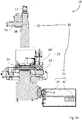
- Figure 10 shows the embodiment of the scanning device of figure 1 in a schematic sectional view.
- the downholder 24 pushes the consumable against the xyz-stage 33, for a flattening fixation of the consumable.
- the illumination objective lens 37 partially projects into a recess within the xyz-stage 33.
- no stray light may enter the beam path at the transition between the xyz-stage 33 and the illumination objective lens 37.
- Figure 11 shows the method for operating the scanning device in a schematic flow chart.
- the scanning device 19 comprises control electronics 29, which may be arranged to perform the following method steps S0, a1), a2), a3), a4), b1), b2), b3), b4) by means of the scanning device 19:
- the sample to be measured in particular the consumable or the chip, is loaded onto the xyz-stage 33. If a sample was arranged on the xyz-stage 33 from a previous measurement, the gripper module 27 unloads that sample from the xyz-stage 33.
- a sample specific focus map is generated.
- the sample is moved to a multiplicity of focus map positions along the x- and y-axis.
- the focus map positions are predefined, in order to capture the entirety of all samples by means of the imaging system.
- an image set is generated by focus stacking along the z-axis at each focus map position.
- the imaging system captures multiple frames, wherein at each frame, the sample is in a different position along the z-axis.
- an optimum z-axis position is determined at each focus map position.
- one of the frames captured in method step a2) is selected according to a predefined criterion.
- the criterion may be the highest sharpness of sample.
- the optimum z-axis positions are assigned to the focus map positions respectively in method step a4).
- the sample is scanned by means of the scanning device 19.
- the sample is moved to a scan position along the x- and y-axis. In particular, the sample is moved to one of the focus map positions.
- the sample is moved to a focus position along the z-axis. In particular, the focus position is the optimum z-axis position, which is determined by means of the object-specific focus map in method-step a3).
- the illumination system is set into dark-field mode, by arranging the circular aperture stop 13 within the beam path.
- the dark-field mode the illumination system illuminates the object within the field of view with the different illumination wavelength ranges consecutively.
- the imaging system captures an image of the sample within the field of view for each assigned detection wavelength range.
- the method steps b1) to b4) are repeated at different scan positions, until the imaging system has captured the entire sample or the entirety of all samples.
- the illumination system may be maintained in dark-field mode, until method step b5) is completed.
- the method step S0 is performed, by moving the xyz-stage 33 to the handover position, in which the gripper module 27 unloads the sample.
- the method steps S0, a1), a2), a3), a4), b1), b2), b3), b4) and b5) may be repeated multiple times, to measure multiple samples, chips or consumables.
- an alternative embodiment of the second optical system 38 in the form of an imaging objective lens is depicted schematically.
- the same is implemented as a mirror system like the Offner relay system.
- the Offner relay system consists of two concentric mirrors, namely a concave mirror 40 and a convex mirror 41. Through the two mirrors, the sample plane 12 is imaged with unit magnification to an image plane 42.
- the Offner relay has nearly diffraction limited imaging performance, is bi-telecentric and is free of distortion due to its symmetric setup. As imaging is accomplished only by reflection, there is zero chromatic aberrations by design.
- the illumination system comprises optical fibers 43, which are arranged to illuminate the sample plane 12 under an angle.
- the optical fibers 43 generate illumination spots, which overlap in the sample plane 12, to generate a homogeneous illumination of the sample plane.
- the figure 13 shows only two fibers 43, but more fibers may improve the homogeneity of the illumination.
- fiber illumination can be accomplished from above or below the sample plane, in order to generate either trans-illumination or reflective illumination.
Landscapes
- Physics & Mathematics (AREA)
- General Physics & Mathematics (AREA)
- Chemical & Material Sciences (AREA)
- Optics & Photonics (AREA)
- Analytical Chemistry (AREA)
- Health & Medical Sciences (AREA)
- Immunology (AREA)
- Life Sciences & Earth Sciences (AREA)
- General Health & Medical Sciences (AREA)
- Biochemistry (AREA)
- Pathology (AREA)
- Nuclear Medicine, Radiotherapy & Molecular Imaging (AREA)
- Engineering & Computer Science (AREA)
- Multimedia (AREA)
- Spectroscopy & Molecular Physics (AREA)
- Chemical Kinetics & Catalysis (AREA)
- Biomedical Technology (AREA)
- Molecular Biology (AREA)
- Investigating, Analyzing Materials By Fluorescence Or Luminescence (AREA)
- Apparatus Associated With Microorganisms And Enzymes (AREA)
- Measuring Or Testing Involving Enzymes Or Micro-Organisms (AREA)
Priority Applications (4)
| Application Number | Priority Date | Filing Date | Title |
|---|---|---|---|
| EP20152206.7A EP3851834B1 (fr) | 2020-01-16 | 2020-01-16 | Dispositif de thermocyclage d'échantillons biologiques, instrument de surveillance le comprenant et procédé de thermocyclage d'échantillons biologiques à l'aide d'un tel dispositif |
| JP2021003303A JP2021113806A (ja) | 2020-01-16 | 2021-01-13 | 生体試料を熱サイクルするための装置、それを含む監視機器、およびそのような装置を使用して生体試料を熱サイクルする方法 |
| CN202110059669.8A CN113138179A (zh) | 2020-01-16 | 2021-01-15 | 用于热循环生物样本的装置、包括该装置的监测仪器以及使用该装置热循环生物样本的方法 |
| US17/149,975 US11650404B2 (en) | 2020-01-16 | 2021-01-15 | Device for thermocycling biological samples, monitoring instrument comprising the same, and method for thermocycling biological samples using such device |
Applications Claiming Priority (1)
| Application Number | Priority Date | Filing Date | Title |
|---|---|---|---|
| EP20152206.7A EP3851834B1 (fr) | 2020-01-16 | 2020-01-16 | Dispositif de thermocyclage d'échantillons biologiques, instrument de surveillance le comprenant et procédé de thermocyclage d'échantillons biologiques à l'aide d'un tel dispositif |
Publications (2)
| Publication Number | Publication Date |
|---|---|
| EP3851834A1 true EP3851834A1 (fr) | 2021-07-21 |
| EP3851834B1 EP3851834B1 (fr) | 2024-06-05 |
Family
ID=69174398
Family Applications (1)
| Application Number | Title | Priority Date | Filing Date |
|---|---|---|---|
| EP20152206.7A Active EP3851834B1 (fr) | 2020-01-16 | 2020-01-16 | Dispositif de thermocyclage d'échantillons biologiques, instrument de surveillance le comprenant et procédé de thermocyclage d'échantillons biologiques à l'aide d'un tel dispositif |
Country Status (4)
| Country | Link |
|---|---|
| US (1) | US11650404B2 (fr) |
| EP (1) | EP3851834B1 (fr) |
| JP (1) | JP2021113806A (fr) |
| CN (1) | CN113138179A (fr) |
Cited By (2)
| Publication number | Priority date | Publication date | Assignee | Title |
|---|---|---|---|---|
| EP4317943A1 (fr) * | 2022-08-04 | 2024-02-07 | Instrumentation Laboratory Company | Capteur optique d'analyte |
| LU102997B1 (en) * | 2022-08-04 | 2024-02-08 | Instr Laboratory Co | Optical analyte sensor |
Families Citing this family (2)
| Publication number | Priority date | Publication date | Assignee | Title |
|---|---|---|---|---|
| CN117940757A (zh) * | 2021-09-15 | 2024-04-26 | 赛默环境设备有限责任公司 | 气体分析仪 |
| CN118067682B (zh) * | 2024-04-16 | 2024-07-05 | 中国人民解放军总医院 | 一种检测生长分化因子15基因表达的方法 |
Citations (5)
| Publication number | Priority date | Publication date | Assignee | Title |
|---|---|---|---|---|
| US20050133724A1 (en) | 2003-12-18 | 2005-06-23 | Palo Alto Research Center Incorporated, A Delaware Corporation | Led or laser enabled real-time PCR system and spectrophotometer |
| US20150204784A1 (en) * | 2011-07-13 | 2015-07-23 | Leica Biosystems Imaging, Inc. | Standardizing fluorescence microscopy systems |
| US20150370058A1 (en) * | 2014-06-23 | 2015-12-24 | Li-Cor, Inc. | Telecentric , wide-field fluorescence scanning systems and methods |
| KR20160029748A (ko) | 2013-05-24 | 2016-03-15 | 라이프 테크놀로지스 코포레이션 | 생물학적 샘플을 위한 케이스 및 케이스 홀더, 그리고 대응하는 사용 방법 |
| US20170241912A1 (en) * | 2016-02-22 | 2017-08-24 | Roche Molecular Systems, Inc. | Optics for analysis of microwells |
Family Cites Families (3)
| Publication number | Priority date | Publication date | Assignee | Title |
|---|---|---|---|---|
| US5835262A (en) * | 1994-12-28 | 1998-11-10 | Research Development Corporation Of Japan | Multi-wavelength optical microscope |
| US9052494B2 (en) * | 2007-10-02 | 2015-06-09 | Kla-Tencor Technologies Corporation | Optical imaging system with catoptric objective; broadband objective with mirror; and refractive lenses and broadband optical imaging system having two or more imaging paths |
| FR2994734B1 (fr) * | 2012-08-21 | 2017-08-25 | Fogale Nanotech | Dispositif et procede pour faire des mesures dimensionnelles sur des objets multi-couches tels que des wafers. |
-
2020
- 2020-01-16 EP EP20152206.7A patent/EP3851834B1/fr active Active
-
2021
- 2021-01-13 JP JP2021003303A patent/JP2021113806A/ja active Pending
- 2021-01-15 CN CN202110059669.8A patent/CN113138179A/zh active Pending
- 2021-01-15 US US17/149,975 patent/US11650404B2/en active Active
Patent Citations (5)
| Publication number | Priority date | Publication date | Assignee | Title |
|---|---|---|---|---|
| US20050133724A1 (en) | 2003-12-18 | 2005-06-23 | Palo Alto Research Center Incorporated, A Delaware Corporation | Led or laser enabled real-time PCR system and spectrophotometer |
| US20150204784A1 (en) * | 2011-07-13 | 2015-07-23 | Leica Biosystems Imaging, Inc. | Standardizing fluorescence microscopy systems |
| KR20160029748A (ko) | 2013-05-24 | 2016-03-15 | 라이프 테크놀로지스 코포레이션 | 생물학적 샘플을 위한 케이스 및 케이스 홀더, 그리고 대응하는 사용 방법 |
| US20150370058A1 (en) * | 2014-06-23 | 2015-12-24 | Li-Cor, Inc. | Telecentric , wide-field fluorescence scanning systems and methods |
| US20170241912A1 (en) * | 2016-02-22 | 2017-08-24 | Roche Molecular Systems, Inc. | Optics for analysis of microwells |
Cited By (2)
| Publication number | Priority date | Publication date | Assignee | Title |
|---|---|---|---|---|
| EP4317943A1 (fr) * | 2022-08-04 | 2024-02-07 | Instrumentation Laboratory Company | Capteur optique d'analyte |
| LU102997B1 (en) * | 2022-08-04 | 2024-02-08 | Instr Laboratory Co | Optical analyte sensor |
Also Published As
| Publication number | Publication date |
|---|---|
| EP3851834B1 (fr) | 2024-06-05 |
| US20210223527A1 (en) | 2021-07-22 |
| JP2021113806A (ja) | 2021-08-05 |
| CN113138179A (zh) | 2021-07-20 |
| US11650404B2 (en) | 2023-05-16 |
Similar Documents
| Publication | Publication Date | Title |
|---|---|---|
| EP3851834B1 (fr) | Dispositif de thermocyclage d'échantillons biologiques, instrument de surveillance le comprenant et procédé de thermocyclage d'échantillons biologiques à l'aide d'un tel dispositif | |
| JP7019300B2 (ja) | 微小ウェルの分析のための光学機器 | |
| US6309601B1 (en) | Scanning optical detection system | |
| US8318094B1 (en) | Substrate analysis systems | |
| US8570370B2 (en) | Compact automated cell counter | |
| EP1955102B1 (fr) | Procedes et dispositifs d'imagerie confocale | |
| EP2745094B1 (fr) | Biocapteur optique ayant une pluralité de régions de capteurs | |
| US8017079B2 (en) | Apparatus for and method of measuring bio-chips using uniform total internal reflection illumination | |
| CN111149037B (zh) | 实时自动对焦聚焦算法 | |
| WO2005113832A2 (fr) | Imageuse grand champ pour analyse quantitative de micromatrices | |
| JP5775693B2 (ja) | 光学照明装置及び方法 | |
| JP7288115B2 (ja) | スライド在庫調べおよび再挿入システム | |
| WO2003067230A1 (fr) | Procede et dispositif de mesure d'une image fluorescente | |
| EP4256289A1 (fr) | Système universel multi-détection pour microplaques à imagerie confocale | |
| US20230221178A1 (en) | Apparatus and a method for fluorescence imaging | |
| US20080253409A1 (en) | Multi-Channel Bio-Chip Scanner | |
| CN219122022U (zh) | 测量微量分光光度计的光路长度的设备及微量分光光度计 | |
| EP2225548B1 (fr) | Système et procédé de détection | |
| KR101188233B1 (ko) | 바이오칩을 위한 진단장치 | |
| US20150041631A1 (en) | Readout & signal transduction (rost) component for poc devices | |
| WO2024098107A1 (fr) | Système d'imagerie non invasif pour l'imagerie de matériaux biologiques | |
| EP4143546A1 (fr) | Diagnostic rapide pour la détection d'analytes/biomarqueurs faisant appel à la technologie raman avec système de mesure raman sans spectromètre |
Legal Events
| Date | Code | Title | Description |
|---|---|---|---|
| PUAI | Public reference made under article 153(3) epc to a published international application that has entered the european phase |
Free format text: ORIGINAL CODE: 0009012 |
|
| STAA | Information on the status of an ep patent application or granted ep patent |
Free format text: STATUS: THE APPLICATION HAS BEEN PUBLISHED |
|
| AK | Designated contracting states |
Kind code of ref document: A1 Designated state(s): AL AT BE BG CH CY CZ DE DK EE ES FI FR GB GR HR HU IE IS IT LI LT LU LV MC MK MT NL NO PL PT RO RS SE SI SK SM TR |
|
| STAA | Information on the status of an ep patent application or granted ep patent |
Free format text: STATUS: REQUEST FOR EXAMINATION WAS MADE |
|
| 17P | Request for examination filed |
Effective date: 20220120 |
|
| RBV | Designated contracting states (corrected) |
Designated state(s): AL AT BE BG CH CY CZ DE DK EE ES FI FR GB GR HR HU IE IS IT LI LT LU LV MC MK MT NL NO PL PT RO RS SE SI SK SM TR |
|
| GRAP | Despatch of communication of intention to grant a patent |
Free format text: ORIGINAL CODE: EPIDOSNIGR1 |
|
| STAA | Information on the status of an ep patent application or granted ep patent |
Free format text: STATUS: GRANT OF PATENT IS INTENDED |
|
| RIC1 | Information provided on ipc code assigned before grant |
Ipc: G02B 21/00 20060101ALI20230831BHEP Ipc: G02B 21/16 20060101ALI20230831BHEP Ipc: G02B 21/06 20060101ALI20230831BHEP Ipc: G01N 21/25 20060101ALI20230831BHEP Ipc: G02B 27/00 20060101ALI20230831BHEP Ipc: G01N 21/64 20060101AFI20230831BHEP |
|
| INTG | Intention to grant announced |
Effective date: 20230927 |
|
| GRAJ | Information related to disapproval of communication of intention to grant by the applicant or resumption of examination proceedings by the epo deleted |
Free format text: ORIGINAL CODE: EPIDOSDIGR1 |
|
| STAA | Information on the status of an ep patent application or granted ep patent |
Free format text: STATUS: REQUEST FOR EXAMINATION WAS MADE |
|
| GRAP | Despatch of communication of intention to grant a patent |
Free format text: ORIGINAL CODE: EPIDOSNIGR1 |
|
| INTC | Intention to grant announced (deleted) | ||
| STAA | Information on the status of an ep patent application or granted ep patent |
Free format text: STATUS: GRANT OF PATENT IS INTENDED |
|
| INTG | Intention to grant announced |
Effective date: 20240104 |
|
| GRAS | Grant fee paid |
Free format text: ORIGINAL CODE: EPIDOSNIGR3 |
|
| GRAA | (expected) grant |
Free format text: ORIGINAL CODE: 0009210 |
|
| STAA | Information on the status of an ep patent application or granted ep patent |
Free format text: STATUS: THE PATENT HAS BEEN GRANTED |
|
| AK | Designated contracting states |
Kind code of ref document: B1 Designated state(s): AL AT BE BG CH CY CZ DE DK EE ES FI FR GB GR HR HU IE IS IT LI LT LU LV MC MK MT NL NO PL PT RO RS SE SI SK SM TR |
|
| REG | Reference to a national code |
Ref country code: CH Ref legal event code: EP |
|
| REG | Reference to a national code |
Ref country code: DE Ref legal event code: R096 Ref document number: 602020031852 Country of ref document: DE |
|
| REG | Reference to a national code |
Ref country code: IE Ref legal event code: FG4D |
|
| REG | Reference to a national code |
Ref country code: LT Ref legal event code: MG9D |