EP3851737A1 - Led retrofit with optical component - Google Patents
Led retrofit with optical component Download PDFInfo
- Publication number
- EP3851737A1 EP3851737A1 EP20152656.3A EP20152656A EP3851737A1 EP 3851737 A1 EP3851737 A1 EP 3851737A1 EP 20152656 A EP20152656 A EP 20152656A EP 3851737 A1 EP3851737 A1 EP 3851737A1
- Authority
- EP
- European Patent Office
- Prior art keywords
- mounting face
- light emitting
- lighting device
- mounting
- lighting
- Prior art date
- Legal status (The legal status is an assumption and is not a legal conclusion. Google has not performed a legal analysis and makes no representation as to the accuracy of the status listed.)
- Pending
Links
- 230000003287 optical effect Effects 0.000 title claims abstract description 46
- 230000005540 biological transmission Effects 0.000 claims description 6
- 229910052736 halogen Inorganic materials 0.000 description 17
- 150000002367 halogens Chemical class 0.000 description 16
- 238000009826 distribution Methods 0.000 description 13
- 230000000875 corresponding effect Effects 0.000 description 11
- 238000000576 coating method Methods 0.000 description 7
- 230000000903 blocking effect Effects 0.000 description 6
- 239000011248 coating agent Substances 0.000 description 6
- 230000003278 mimic effect Effects 0.000 description 6
- 239000011521 glass Substances 0.000 description 5
- 229920003023 plastic Polymers 0.000 description 3
- 238000010521 absorption reaction Methods 0.000 description 2
- XAGFODPZIPBFFR-UHFFFAOYSA-N aluminium Chemical compound [Al] XAGFODPZIPBFFR-UHFFFAOYSA-N 0.000 description 2
- 229910052782 aluminium Inorganic materials 0.000 description 2
- 238000005516 engineering process Methods 0.000 description 2
- -1 H7 halogen Chemical class 0.000 description 1
- 230000000694 effects Effects 0.000 description 1
- 230000004313 glare Effects 0.000 description 1
- 230000031700 light absorption Effects 0.000 description 1
- 239000000463 material Substances 0.000 description 1
- 238000000034 method Methods 0.000 description 1
- 238000007493 shaping process Methods 0.000 description 1
- 238000004544 sputter deposition Methods 0.000 description 1
Images


Classifications
-
- F—MECHANICAL ENGINEERING; LIGHTING; HEATING; WEAPONS; BLASTING
- F21—LIGHTING
- F21S—NON-PORTABLE LIGHTING DEVICES; SYSTEMS THEREOF; VEHICLE LIGHTING DEVICES SPECIALLY ADAPTED FOR VEHICLE EXTERIORS
- F21S41/00—Illuminating devices specially adapted for vehicle exteriors, e.g. headlamps
- F21S41/10—Illuminating devices specially adapted for vehicle exteriors, e.g. headlamps characterised by the light source
- F21S41/14—Illuminating devices specially adapted for vehicle exteriors, e.g. headlamps characterised by the light source characterised by the type of light source
- F21S41/141—Light emitting diodes [LED]
- F21S41/147—Light emitting diodes [LED] the main emission direction of the LED being angled to the optical axis of the illuminating device
-
- F—MECHANICAL ENGINEERING; LIGHTING; HEATING; WEAPONS; BLASTING
- F21—LIGHTING
- F21K—NON-ELECTRIC LIGHT SOURCES USING LUMINESCENCE; LIGHT SOURCES USING ELECTROCHEMILUMINESCENCE; LIGHT SOURCES USING CHARGES OF COMBUSTIBLE MATERIAL; LIGHT SOURCES USING SEMICONDUCTOR DEVICES AS LIGHT-GENERATING ELEMENTS; LIGHT SOURCES NOT OTHERWISE PROVIDED FOR
- F21K9/00—Light sources using semiconductor devices as light-generating elements, e.g. using light-emitting diodes [LED] or lasers
- F21K9/20—Light sources comprising attachment means
- F21K9/23—Retrofit light sources for lighting devices with a single fitting for each light source, e.g. for substitution of incandescent lamps with bayonet or threaded fittings
- F21K9/232—Retrofit light sources for lighting devices with a single fitting for each light source, e.g. for substitution of incandescent lamps with bayonet or threaded fittings specially adapted for generating an essentially omnidirectional light distribution, e.g. with a glass bulb
-
- F—MECHANICAL ENGINEERING; LIGHTING; HEATING; WEAPONS; BLASTING
- F21—LIGHTING
- F21S—NON-PORTABLE LIGHTING DEVICES; SYSTEMS THEREOF; VEHICLE LIGHTING DEVICES SPECIALLY ADAPTED FOR VEHICLE EXTERIORS
- F21S41/00—Illuminating devices specially adapted for vehicle exteriors, e.g. headlamps
- F21S41/10—Illuminating devices specially adapted for vehicle exteriors, e.g. headlamps characterised by the light source
- F21S41/14—Illuminating devices specially adapted for vehicle exteriors, e.g. headlamps characterised by the light source characterised by the type of light source
- F21S41/141—Light emitting diodes [LED]
- F21S41/151—Light emitting diodes [LED] arranged in one or more lines
-
- F—MECHANICAL ENGINEERING; LIGHTING; HEATING; WEAPONS; BLASTING
- F21—LIGHTING
- F21S—NON-PORTABLE LIGHTING DEVICES; SYSTEMS THEREOF; VEHICLE LIGHTING DEVICES SPECIALLY ADAPTED FOR VEHICLE EXTERIORS
- F21S41/00—Illuminating devices specially adapted for vehicle exteriors, e.g. headlamps
- F21S41/40—Illuminating devices specially adapted for vehicle exteriors, e.g. headlamps characterised by screens, non-reflecting members, light-shielding members or fixed shades
- F21S41/43—Illuminating devices specially adapted for vehicle exteriors, e.g. headlamps characterised by screens, non-reflecting members, light-shielding members or fixed shades characterised by the shape thereof
Definitions
- the present disclosure relates to a lighting device comprising at least one optical component in particular configured to adjust a ratio of an intensity of light such that the lighting element may be suitably employed as retrofit mimicking a halogen lamp e.g. for an automotive headlight.
- the present disclosure further, relates to an automotive headlight.
- Lighting devices such as halogen lamps have been standard light sources for automotive headlights for many years.
- LED technology recent advances in LED technology and energy efficiency has spurred interest in finding suitable replacements for halogen lamps based on LED technology, such replacement being often referred to as LED retrofit.
- LED retrofits have become popular in recent years, capabilities of LED retrofits in mimicking halogen lamps are not yet optimal.
- a reason therefor lies in differing geometries of light emission regions of halogen lamps (filament) and e.g. LED dies (light emission surfaces).
- intensity distributions of light emitted from LED arrangements of existing LED retrofits differ from corresponding intensity distributions of light emitted from halogen lamps and may result in light emission disturbing and endangering oncoming traffic when used in combination with existing headlight reflectors and optics.
- An approach to mimic a halogen lamp filament is to arrange three rows of LEDs, in particular LED dies, on three respective surfaces (mounting faces) of an elongated, essentially cuboidal, mounting section to emit light in three respective directions. While such LED arrangement is suitable to mimic a near-field luminance profile of a halogen lamp, mimicking also a far-field luminance profile of a halogen lamp still remains a problem to be solved. It was found that in case of the three row arrangement, a superposition of usually Lambertian light intensity profiles of individual LEDs causes undesirable intensity peaks in lighting directions forming an angle of 45° with respective surface normals of adjacent mounting faces.
- a lighting device comprising a mounting section comprising a first mounting face and a second mounting face arranged at an angle, in particular of 90° ⁇ 5°, in particular ⁇ 2°, with respect to the first mounting face; a first light emitting element arranged on the first mounting face and a second light emitting element arranged on the second mounting face; and an optical component configured to adjust a ratio of an intensity of light emitted from the first and second light emitting elements in a first lighting direction to an intensity of light emitted from the first and second light emitting elements in a second lighting direction, wherein the second lighting direction is along a surface normal of the first or second mounting face and the first lighting direction is at an angle, in particular of 45° ⁇ 5°, in particular ⁇ 2°, with respect to the second lighting direction.
- an automotive headlight comprising such a lighting device.
- Exemplary embodiments of the first and second aspects of the invention may have one or more of the properties described below.
- the optical component is or comprises an optical element configured for at least partially absorbing, reflecting, and/or refracting light, in particular at least along the first direction.
- the optical component may in an exemplary embodiment thus correspond to or comprise an optical absorption element, an optical reflection element, a prism, and/or an optical filter.
- the optical component is configured to adjust the ratio of the intensity of light emitted in the first lighting direction to the intensity of light emitted in the second lighting direction by reducing the intensity emitted along the first lighting direction.
- “along the first lighting direction” is to be understood as encompassing an angular distribution centered around the first direction of e.g. ⁇ 30° (a 60° cone angle), in particular of ⁇ 15°, in particular of ⁇ 10°.
- the optical component is configured to adjust an angular intensity distribution of light emitted from the first and second light emitting elements reducing an intensity emitted at angles in between surface normals of adjacent mounting faces.
- an intensity of light emitted under 45° ( ⁇ 30°) and/or 135° ( ⁇ 30°) is reduced, in particular without affecting a light intensity along the second lighting direction (and within an angular region centered around the second lighting direction of e.g. ⁇ 30° (a 60° cone angle), in particular of ⁇ 15°, and further in particular of ⁇ 10°).
- an intensity distribution of light emitted from the lighting device is highly improved.
- the lighting device when used in a vehicular, e.g. automotive, headlight, and is thus used with typical headlight optics, unwanted effects such as glare potentially disturbing oncoming traffic can be reduced.
- the optical component thus helps to mitigate the otherwise existing undesirable intensity peaks and therefore allows for the inventive lighting device to not only suitably mimic an intensity distribution of a halogen lamp in the near-field but also in the far-field.
- the first lighting direction forms a same angle with respect to the surface normal of the first mounting face and with respect to the surface normal of the second mounting face.
- the first and the second mounting faces are adjacent mounting faces, i.e. are connected with each other by a portion of the mounting section at which no light emitting elements are mounted.
- the first lighting direction is at an angle bisecting an angle formed by the surface normal of the first mounting face and the surface normal of the second mounting face.
- the first mounting face and the second mounting face are arranged at an angle of 90° ⁇ 5°, in particular ⁇ 2°, with respect to each other, and the first lighting direction is at an angle of 45° ⁇ 5°, in particular ⁇ 2°, with respect to the surface normal of the first mounting face and at an angle of 45° ⁇ 5°, in particular ⁇ 2°, with respect to the surface normal of the second mounting face.
- the optical component thus advantageously affects directions in which Lambertian emissions of respective light emitting elements could otherwise cause undesirable intensity peaks.
- the mounting section corresponds to a member elongated along a corresponding longitudinal axis.
- the first light emitting element corresponds to an arrangement of at least two first light emitting elements arranged on the first mounting face along the longitudinal axis of the mounting section.
- the at least one second light emitting element corresponds to an arrangement of at least two second light emitting elements arranged on the second mounting face along the longitudinal axis of the mounting section.
- the mounting section further comprises a third mounting face arranged adjacent to the second mounting face and opposing the first mounting face, and at least two third light emitting elements are arranged on the third mounting face along the longitudinal axis of the mounting section.
- Such configuration with an elongated mounting section and corresponding longitudinal arrangements of light emitting elements advantageously enables mimicking properties of a filament of a halogen lamp in particular in the near-field.
- the third mounting face is arranged at an angle of 90° ⁇ 5°, in particular ⁇ 2°, with respect to the second mounting face and is arranged essentially parallel (at an angle of 0° ⁇ 5°, in particular ⁇ 2°) with respect to the first mounting face. In this way, it becomes possible to arrange light emitting elements to emit light in three mutually orthogonal directions to advantageously mimic a corresponding property of a halogen lamp filament.
- the first light emitting element, the second light emitting element, and/or the third light emitting element comprises a light emitting diode (LED), in particular an LED die.
- LED light emitting diode
- Use of LEDs advantageously enables provision of a highly efficient light source that can be designed e.g. in terms of light color and/or temperature to suitably match corresponding demands e.g. in the field of automotive headlights.
- the optical component is configured to reduce the intensity of light emitted from the first and second light emitting elements in the first lighting direction by at least 10%, in particular by at least 17%, in particular by at least 25%, in particular by at least 30%, in particular by at least 35%, and in particular by at least 40%.
- the optical component is thus advantageously suited to remove undesirable intensity peaks in areas in which for example side portions of Lambertian emission of corresponding light emitting elements are superimposed.
- the optical component is arranged at the lighting device to not affect the intensity of light emitted from the first and second light emitting elements in the second lighting direction.
- the optical component is configured to allow for transmission of light emitted from the first and second light emitting elements in the second lighting direction to at least 80%, in particular to at least 90%, in particular to at least 95%.
- the optical component is arranged at the lighting device and/or configured to reduce intensity only where needed, i.e., in regions where overlapping intensity distributions of different light emitting elements undesirably cause intensity peaks, while at least essentially not affecting intensity in regions where the corresponding requirements are already fulfilled.
- a driving current for driving the light emitting elements may be increased accordingly. It was found that an increase in driving current needed to cope with an intensity reduction along the first lighting direction can be kept within limits tolerable for light emitting elements such as LEDs.
- the optical component is configured to reduce the intensity of light emitted from the first and second light emitting elements in the first lighting direction by absorbing and/or reflecting light emitted in the first lighting direction and/or by refracting light emitted from the first and second light emitting elements at least partially away from the first lighting direction.
- at least a portion of the optical component where light intensity needs to be reduced may be made less transparent, for example 30-40% less transparent, for instance by applying an absorbing coating on a side of the optical component (e.g. a plane or curved glass or transparent plastic member) facing the mounting section.
- the optical component may comprise an at least partially reflective portion facing the mounting section.
- about 30% e.g.
- a partially reflective portion may be made e.g. by sputtering aluminum.
- the optical component comprises a partially reflective portion comprising aluminum.
- the partially reflective portion comprises a dielectric mirror.
- absorptive or reflective coating may for example be placed on an outside or inside of a glass bulb.
- the optical component comprises an at least partially absorptive and/or at least partially reflective shield.
- shield is to be understood as a device that reduces transmission of light emitted from the first and second light emitting elements in the first lighting direction.
- the at least partially absorptive and/or at least partially reflective shield comprises glass or a transparent plastic and (e.g. provided with) an absorptive and/or reflective coating.
- the coating is provided on a side of the shield facing the mounting section. In particular the latter arrangement turned out to be advantageous as it helps to prevent light from entering the shield (in a light guide mode of the shield) and to be undesirably guided to an exit portion where it could otherwise again cause undesirable light peaks.
- the at least partially absorptive and/or at least partially reflective shield is at least partially curved, wherein a corresponding radius of curvature of the at least partially absorptive and/or at least partially reflective shield corresponds to a distance between the mounting section and the at least partially absorptive and/or at least partially reflective shield.
- “corresponds to” is to be understood in that the radius of curvature is equal to said distance ⁇ 20%, in particular ⁇ 15%, in particular ⁇ 10%, in particular ⁇ 5%. It turned out that this form of the optical component is in particular advantageous in terms of efficiency regarding space and material requirements. It is noted that, e.g. as opposed to the use of a closed glass bulb provided with suitable absorptive and/or reflective coatings, use of the shield turned out to be advantageous as it advantageously allows transport of heat generated by the light emitting elements away from the lighting device.
- the optical component is arranged at the lighting device and configured to at least partially block/absorb/reflect light.
- the optical component may correspond to or comprise one or more prisms, e.g. a single larger prism or a plurality of smaller (e.g. Fresnel-) prisms that are arranged in close vicinity of light emission portions of the selected light emitting elements.
- close vicinity is to be understood such that a gap, e.g. an air gap, is present between the one or more prisms and the corresponding light emission portions of the light emitting elements.
- the optical component comprises a prism assigned to the (arranged in correspondence with the/arranged to collect light from the/arranged next to a light emitting portion of the) first light emitting element arranged on the first mounting face and/or to the third light emitting element arranged on the third mounting face.
- the prism is arranged next to a light emitting portion of the light emitting elements arranged on the first, the second and/or the third mounting faces, a gap, e.g. an air gap, separating the prism and the light emitting portion of the light emitting elements.
- an intensity distribution in particular of light emitted from the first (and/or third) light emitting element arranged on the first (and/or third) mounting face, may be made narrower to reduce an intensity in regions of overlap and to thus reduce the undesired intensity peaks.
- an angle selective filter for example brightness enhancement optics such as e.g. Fresnel structures, may advantageously be employed.
- the optical component comprises an angle selective filter assigned to the first light emitting element arranged on the first mounting face and/or to the third light emitting element arranged on the third mounting face and configured to allow for light transmission within an angular range smaller than an angular range of a light transmission from a light emitting surface of the first and/or third light emitting elements.
- the angle selective filter comprises a prism array and/or a brightness enhancement film.
- Figure 1 shows a headlight 100 with a reflector 120 to which an exemplary H7 halogen lamp 110 is mounted.
- a filament 111 of halogen lamp 110 is placed at a focus of reflector 120 such that light 132 emitted from filament 111 is reflected by the reflector 120 along a main lighting direction 150.
- a cover 121 may incorporate suitable optics for shaping the reflected light and to form light 133 leaving headlight 100.
- Lamp 110 comprises a socket 114 mounted to reflector 120 via mounting portion 116. Pins 117a and 117b extend from socket 114 for power connection.
- Bulb 113 extends from base portion 115 surrounding filament 111 and ends in a light blocking portion 112 which blocks direct light from filament 111.
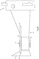
- Figure 2A shows a side-view of a retrofit lamp 1 (an example of a lighting device according to an exemplary embodiment), lamp 1 being oriented in correspondence with lamp 100 of Fig. 1 .
- a body 13 extends in between a light blocking portion 12 and a socket 14, and serves in particular as heat sink for heat generated by light emitting diodes (LEDs, examples of light emitting elements) 11.
- LEDs light emitting diodes
- Two rows 11 of LEDs are respectively arranged on a first mounting face 18a and a second mounting face 18b of a mounting section 18 arranged on a support part 13a of body 13.
- LEDs 11a, 11b, 11c, 11d and 11e form an arrangement 11 of at least two first light emitting elements arranged on the first mounting face 18a along a longitudinal axis of mounting section 18 which in the present example is parallel to the main lighting direction 150.
- a further row 11 of LEDs is arranged on a third mounting face 18c opposing the first mounting face 18a (see Figs. 2B and 2C ).
- Figure 2A further shows an at least partially absorptive and/or at least partially reflective shield (an optical component) 31 arranged at lamp 1 to reduce an intensity of light emitted from the LEDs arranged on the first and second mounting faces 18a, 18b in a direction at an angle of 45° ⁇ 30° with respect to the surface normal of the first mounting face 18a and with respect to the surface normal of the second mounting face 18b.
- a further shield 31 is arranged to reduce overlapping intensities of light emitted from LEDs respectively arranged on the second mounting face 18b and a third mounting face 18c.
- shields 31 may be supported by transparent support sections 33 attached to socket 14 and/or body 13 and/or to light blocking portion 12 (see Fig. 2A ).
- shield 31 and support sections 33 may be comprised by an integral glass or transparent plastic member provided with a suitable absorption and/or reflection coating on a face of said member facing mounting section 18 to form an at least partially absorptive and/or at least partially reflective shield 31. It is noted that portions of shield 31 covering areas where light absorption/reflection is not desirable (covering the second direction) may be provided with a a broad band anti-reflection coating in order to minimize light losses.
- Figure 2C shows a cross-sectional view of lamp 1 of Figs. 2A and 2B .
- shield 31 to the right of the figure is centered around the first lighting direction 153, the first lighting direction being at an angle of 45° with respect to a second lighting direction 151 along the surface normal of the first mounting face 18a and to a further second lighting direction 155 along the surface normal of the second mounting face 18b.
- the at least partially absorptive and/or at least partially reflective shield 31 is centered with respect to a virtual plane (in direction 153) including the longitudinal axis of the mounting section 18 (perpendicular to the drawing plane) and bisecting an angle formed by the surface normal of the first mounting face 18a and the surface normal of the second mounting face 18b.
- shield 31 covers an angle of 45° ⁇ 30° with respect to the surface normal of the second mounting face 18b (an angular coverage of 60°).
- the at least partially absorptive and/or at least partially reflective shield 31 covers an angular range of ⁇ 10°, in particular of ⁇ 20°, in particular of ⁇ 30° with respect to the virtual plane.
- Figures 3A and 3B illustrate a further exemplary embodiment of an optical component 40 in form of respective prisms 40 arranged adjacent to the first light emitting element arranged on the first mounting face 18a and/or to the third light emitting element arranged on the third mounting face 18c.
- an air gap 19 is formed between the at least one prism 40 and a light emitting surface of the first light emitting element arranged on the first mounting face 18a and/or a light emitting surface of third light emitting element arranged on the third mounting face 18c.
- Prisms 40 deflect light (along deflecting directions 152, 158) from LED arrangements 11 on mounting faces 18a, 18c towards body 13 (away from the second lighting directions 151 and 157, i.e., away from the surface normals of the first and third mounting faces 18a, 18c).
- the intensity along the first lighting direction 153 of 45° with respect to the surface normal of the second mounting face 18b is reduced.
- Airgap 19 between respective light emitting surfaces of the LEDs 11 and prisms 40 advantageously helps to allow for the deflection.
- prism 40 can be realized as a prism bar 40 attached to light blocking portion 12 and body 13 (see Fig. 3B ) at respective attachment sections 41, 43.
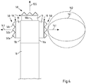
- Figure 4 shows a further exemplary embodiment of an optical component 50 which is configured as angle selective filter (which may be referred to also as brightness enhancement optic) assigned to a respective LED arrangement 11 and configured to narrow respective light intensity profiles of LEDs to thereby reduce the projected light emitting area and to thus reduce intensity in regions of overlap between LEDs of neighbouring arrangements.
- an intensity distribution 162 without optical component 50 is narrowed into intensity distribution 161 with optical component 50.
- optical component 50 helps to reduce an intensity along a first lighting direction 153 at an angle of 45° with respect to the surface normal of the second mounting face 18b and to thereby suitably adjust the beam profile on the road.
- the angle selective filter 50 is realized as an array of prisms 50a, 50b, 50c assigned to a respective arrangement 11 of LEDs, whereby an air gap 19 is present between the optical component 50 and light emitting surfaces of the respective LEDs.
- the prism array 50 may be mounted to the lighting device 1 in a similar fashion as optical component 40 in Fig. 3B .
- Lighting device 1 LED arrangement 11 LEDs 11a, 11b, 11c, 11d, 11e Light blocking portion 12 Body 13 Support part 13a Socket 14 Mounting section 18 Mounting face 18a, 18b, 18c Air gap 19 Shield 31 Support sections 33 Prism, prism bar 40 Attachment sections 41, 43 Angle selective filter 50 Prisms 50a, 50b, 50c Headlight 100 Halogen lamp 110 Filament 111 Light blocking portion 112 Bulb 113 Socket 114 Base portion 115 Mounting portion 116 Pins 117a, 117b Reflector 120 Cover 121 Light rays 132, 133 Main lighting direction 150 First lighting direction 153 Second lighting directions 151, 155, 157 Deflecting directions 152, 158 Intensity distribution with angle selective filter 161 Intensity distribution without angle selective filter 162 edge-to-edge distance of shield 31 d curvature radius of shield 31 R
Landscapes
- Engineering & Computer Science (AREA)
- General Engineering & Computer Science (AREA)
- Physics & Mathematics (AREA)
- Microelectronics & Electronic Packaging (AREA)
- Optics & Photonics (AREA)
- Non-Portable Lighting Devices Or Systems Thereof (AREA)
Abstract
According to the invention a lighting device (1) is provided comprising:- a mounting section (18) comprising a first mounting face (18a) and a second mounting face (18b) arranged at an angle with respect to the first mounting face (18a);- a first light emitting element (11a, 11b, 11c, 11d, 11e) arranged on the first mounting face (18a) and a second light emitting element (11a, 11b, 11c, 11d, 11e) arranged on the second mounting face (18b); and- an optical component (31, 40, 50) configured to adjust a ratio of an intensity of light emitted from the first and second light emitting elements (11a, 11b, 11c, 11d, 11e) in a first lighting direction (153) to an intensity of light emitted from the first and second light emitting elements (11a, 11b, 11c, 11d, 11e) in a second lighting direction (151, 155), wherein the second lighting direction (151, 155) is along a surface normal of the first (18a) or second (18b) mounting face, and the first lighting direction (153) is at an angle with respect to the second lighting direction (151, 155).The invention also provides an automotive headlight with such lighting device (1).
Description
- The present disclosure relates to a lighting device comprising at least one optical component in particular configured to adjust a ratio of an intensity of light such that the lighting element may be suitably employed as retrofit mimicking a halogen lamp e.g. for an automotive headlight. The present disclosure, further, relates to an automotive headlight.
- Lighting devices such as halogen lamps have been standard light sources for automotive headlights for many years. However, recent advances in LED technology and energy efficiency has spurred interest in finding suitable replacements for halogen lamps based on LED technology, such replacement being often referred to as LED retrofit.
- While LED retrofits have become popular in recent years, capabilities of LED retrofits in mimicking halogen lamps are not yet optimal. A reason therefor lies in differing geometries of light emission regions of halogen lamps (filament) and e.g. LED dies (light emission surfaces). As a result, in particular, intensity distributions of light emitted from LED arrangements of existing LED retrofits differ from corresponding intensity distributions of light emitted from halogen lamps and may result in light emission disturbing and endangering oncoming traffic when used in combination with existing headlight reflectors and optics.
- An approach to mimic a halogen lamp filament is to arrange three rows of LEDs, in particular LED dies, on three respective surfaces (mounting faces) of an elongated, essentially cuboidal, mounting section to emit light in three respective directions. While such LED arrangement is suitable to mimic a near-field luminance profile of a halogen lamp, mimicking also a far-field luminance profile of a halogen lamp still remains a problem to be solved. It was found that in case of the three row arrangement, a superposition of usually Lambertian light intensity profiles of individual LEDs causes undesirable intensity peaks in lighting directions forming an angle of 45° with respective surface normals of adjacent mounting faces.
- It is thus an object of the present invention to provide a lighting device with improved capability to mimic light emission properties of a conventional halogen lamp. It is a further object of the present invention to provide a corresponding automotive headlight.
- According to a first aspect of the present invention, a lighting device is provided, the lighting device comprising a mounting section comprising a first mounting face and a second mounting face arranged at an angle, in particular of 90°±5°, in particular ±2°, with respect to the first mounting face; a first light emitting element arranged on the first mounting face and a second light emitting element arranged on the second mounting face; and an optical component configured to adjust a ratio of an intensity of light emitted from the first and second light emitting elements in a first lighting direction to an intensity of light emitted from the first and second light emitting elements in a second lighting direction, wherein the second lighting direction is along a surface normal of the first or second mounting face and the first lighting direction is at an angle, in particular of 45°±5°, in particular ±2°, with respect to the second lighting direction.
- According to a second aspect of the present invention, an automotive headlight is provided comprising such a lighting device.
- Exemplary embodiments of the first and second aspects of the invention may have one or more of the properties described below.
- In an exemplary embodiment, the optical component is or comprises an optical element configured for at least partially absorbing, reflecting, and/or refracting light, in particular at least along the first direction. The optical component may in an exemplary embodiment thus correspond to or comprise an optical absorption element, an optical reflection element, a prism, and/or an optical filter.
- In an exemplary embodiment, the optical component is configured to adjust the ratio of the intensity of light emitted in the first lighting direction to the intensity of light emitted in the second lighting direction by reducing the intensity emitted along the first lighting direction. It is noted that "along the first lighting direction" is to be understood as encompassing an angular distribution centered around the first direction of e.g. ±30° (a 60° cone angle), in particular of ±15°, in particular of ±10°. In other words, the optical component is configured to adjust an angular intensity distribution of light emitted from the first and second light emitting elements reducing an intensity emitted at angles in between surface normals of adjacent mounting faces. For example, in case that adjacent mounting faces form an angle of 90°, an intensity of light emitted under 45° (±30°) and/or 135° (±30°) is reduced, in particular without affecting a light intensity along the second lighting direction (and within an angular region centered around the second lighting direction of e.g. ±30° (a 60° cone angle), in particular of ±15°, and further in particular of ±10°).
- Thereby, an intensity distribution of light emitted from the lighting device is highly improved. For example, when the lighting device is used in a vehicular, e.g. automotive, headlight, and is thus used with typical headlight optics, unwanted effects such as glare potentially disturbing oncoming traffic can be reduced. The optical component thus helps to mitigate the otherwise existing undesirable intensity peaks and therefore allows for the inventive lighting device to not only suitably mimic an intensity distribution of a halogen lamp in the near-field but also in the far-field.
- In an exemplary embodiment, the first lighting direction forms a same angle with respect to the surface normal of the first mounting face and with respect to the surface normal of the second mounting face. Thereby, in an exemplary embodiment, the first and the second mounting faces are adjacent mounting faces, i.e. are connected with each other by a portion of the mounting section at which no light emitting elements are mounted. Thus, the first lighting direction is at an angle bisecting an angle formed by the surface normal of the first mounting face and the surface normal of the second mounting face. In an exemplary embodiment, the first mounting face and the second mounting face are arranged at an angle of 90°±5°, in particular ±2°, with respect to each other, and the first lighting direction is at an angle of 45°±5°, in particular ±2°, with respect to the surface normal of the first mounting face and at an angle of 45°±5°, in particular ±2°, with respect to the surface normal of the second mounting face. The optical component thus advantageously affects directions in which Lambertian emissions of respective light emitting elements could otherwise cause undesirable intensity peaks.
- In an exemplary embodiment, the mounting section corresponds to a member elongated along a corresponding longitudinal axis. In an exemplary embodiment, the first light emitting element corresponds to an arrangement of at least two first light emitting elements arranged on the first mounting face along the longitudinal axis of the mounting section. In an exemplary embodiment, the at least one second light emitting element corresponds to an arrangement of at least two second light emitting elements arranged on the second mounting face along the longitudinal axis of the mounting section. In an exemplary embodiment, the mounting section further comprises a third mounting face arranged adjacent to the second mounting face and opposing the first mounting face, and at least two third light emitting elements are arranged on the third mounting face along the longitudinal axis of the mounting section. Such configuration with an elongated mounting section and corresponding longitudinal arrangements of light emitting elements advantageously enables mimicking properties of a filament of a halogen lamp in particular in the near-field. In an exemplary embodiment, the third mounting face is arranged at an angle of 90°±5°, in particular ±2°, with respect to the second mounting face and is arranged essentially parallel (at an angle of 0°±5°, in particular ±2°) with respect to the first mounting face. In this way, it becomes possible to arrange light emitting elements to emit light in three mutually orthogonal directions to advantageously mimic a corresponding property of a halogen lamp filament.
- In an exemplary embodiment, the first light emitting element, the second light emitting element, and/or the third light emitting element comprises a light emitting diode (LED), in particular an LED die. Use of LEDs advantageously enables provision of a highly efficient light source that can be designed e.g. in terms of light color and/or temperature to suitably match corresponding demands e.g. in the field of automotive headlights.
- In an exemplary embodiment, the optical component is configured to reduce the intensity of light emitted from the first and second light emitting elements in the first lighting direction by at least 10%, in particular by at least 17%, in particular by at least 25%, in particular by at least 30%, in particular by at least 35%, and in particular by at least 40%. The optical component is thus advantageously suited to remove undesirable intensity peaks in areas in which for example side portions of Lambertian emission of corresponding light emitting elements are superimposed. In an exemplary embodiment, for example in addition to other features, the optical component is arranged at the lighting device to not affect the intensity of light emitted from the first and second light emitting elements in the second lighting direction. Alternatively or in addition, in an exemplary embodiment, the optical component is configured to allow for transmission of light emitted from the first and second light emitting elements in the second lighting direction to at least 80%, in particular to at least 90%, in particular to at least 95%. In other words, the optical component is arranged at the lighting device and/or configured to reduce intensity only where needed, i.e., in regions where overlapping intensity distributions of different light emitting elements undesirably cause intensity peaks, while at least essentially not affecting intensity in regions where the corresponding requirements are already fulfilled. It is noted that in order to cope with an overall loss of intensity that may be caused by the optical component, for example, a driving current for driving the light emitting elements may be increased accordingly. It was found that an increase in driving current needed to cope with an intensity reduction along the first lighting direction can be kept within limits tolerable for light emitting elements such as LEDs.
- In an exemplary embodiment, the optical component is configured to reduce the intensity of light emitted from the first and second light emitting elements in the first lighting direction by absorbing and/or reflecting light emitted in the first lighting direction and/or by refracting light emitted from the first and second light emitting elements at least partially away from the first lighting direction. In other words, at least a portion of the optical component where light intensity needs to be reduced may be made less transparent, for example 30-40% less transparent, for instance by applying an absorbing coating on a side of the optical component (e.g. a plane or curved glass or transparent plastic member) facing the mounting section. In a further example, the optical component may comprise an at least partially reflective portion facing the mounting section. Similarly, also in this case, about 30% (e.g. 30%-40%) of light may be reflected (e.g. back towards the mounting section/towards the light emitting elements) while for example 70% (e.g. 60%-70%) of light may pass the optical component. A partially reflective portion may be made e.g. by sputtering aluminum. Thus, in an exemplary embodiment, the optical component comprises a partially reflective portion comprising aluminum. Alternatively or in addition, in an exemplary embodiment, the partially reflective portion comprises a dielectric mirror. Such absorptive or reflective coating may for example be placed on an outside or inside of a glass bulb.
- In an exemplary embodiment, the optical component comprises an at least partially absorptive and/or at least partially reflective shield. It is noted that shield is to be understood as a device that reduces transmission of light emitted from the first and second light emitting elements in the first lighting direction. In an exemplary embodiment, the at least partially absorptive and/or at least partially reflective shield comprises glass or a transparent plastic and (e.g. provided with) an absorptive and/or reflective coating. In an exemplary embodiment, the coating is provided on a side of the shield facing the mounting section. In particular the latter arrangement turned out to be advantageous as it helps to prevent light from entering the shield (in a light guide mode of the shield) and to be undesirably guided to an exit portion where it could otherwise again cause undesirable light peaks.
- In an exemplary embodiment, the at least partially absorptive and/or at least partially reflective shield is at least partially curved, wherein a corresponding radius of curvature of the at least partially absorptive and/or at least partially reflective shield corresponds to a distance between the mounting section and the at least partially absorptive and/or at least partially reflective shield. In this connection, "corresponds to" is to be understood in that the radius of curvature is equal to said distance ±20%, in particular ±15%, in particular ±10%, in particular ±5%. It turned out that this form of the optical component is in particular advantageous in terms of efficiency regarding space and material requirements. It is noted that, e.g. as opposed to the use of a closed glass bulb provided with suitable absorptive and/or reflective coatings, use of the shield turned out to be advantageous as it advantageously allows transport of heat generated by the light emitting elements away from the lighting device.
- Thus, according to the above embodiment, the optical component is arranged at the lighting device and configured to at least partially block/absorb/reflect light. Thereby, it becomes possible not only to mimic the near-field properties of a halogen lamp but also advantageously corresponding far-field properties.
- In addition or alternatively, light of selected light emitting elements may be deflected so that that less light is superimposed at angles between the surface normals of the first and second mounting faces. To this end, the optical component may correspond to or comprise one or more prisms, e.g. a single larger prism or a plurality of smaller (e.g. Fresnel-) prisms that are arranged in close vicinity of light emission portions of the selected light emitting elements. Thereby, "close vicinity" is to be understood such that a gap, e.g. an air gap, is present between the one or more prisms and the corresponding light emission portions of the light emitting elements.
- Thus, in an exemplary embodiment, the optical component comprises a prism assigned to the (arranged in correspondence with the/arranged to collect light from the/arranged next to a light emitting portion of the) first light emitting element arranged on the first mounting face and/or to the third light emitting element arranged on the third mounting face. In other words, in an exemplary embodiment, the prism is arranged next to a light emitting portion of the light emitting elements arranged on the first, the second and/or the third mounting faces, a gap, e.g. an air gap, separating the prism and the light emitting portion of the light emitting elements.
- As a result, in case that one or more prisms are assigned to the first (and/or third) light emitting element arranged on the first (and/or third) mounting face, light is deflected away from light emitted from the second light emitting element arranged on the second mounting face such that intensity of light emitted along the first lighting direction is reduced. In other words, by assigning the one or more prisms to the respective light emitting elements, an asymmetric intensity distribution is achieved which helps to reduce the undesired intensity peaks.
- In a further embodiment, instead of deflecting light away, an intensity distribution, in particular of light emitted from the first (and/or third) light emitting element arranged on the first (and/or third) mounting face, may be made narrower to reduce an intensity in regions of overlap and to thus reduce the undesired intensity peaks. To this end, an angle selective filter, for example brightness enhancement optics such as e.g. Fresnel structures, may advantageously be employed.
- Thus, in an exemplary embodiment, the optical component comprises an angle selective filter assigned to the first light emitting element arranged on the first mounting face and/or to the third light emitting element arranged on the third mounting face and configured to allow for light transmission within an angular range smaller than an angular range of a light transmission from a light emitting surface of the first and/or third light emitting elements. In an exemplary embodiment, the angle selective filter comprises a prism array and/or a brightness enhancement film.
- It is to be understood that the presentation of embodiments of the invention in this section is merely exemplary and non-limiting.
- Other features of the present invention will become apparent from the following detailed description considered in conjunction with the accompanying drawings. It is to be understood, however, that the drawings are designed solely for purposes of illustration and not as a definition of the limits of the invention, for which reference should be made to the appended claims. It should be further understood that the drawings are not drawn to scale and are merely intended to conceptually illustrate the structures and procedures described herein.
- Examples of the invention will now be described in detail with reference to the accompanying drawings, in which:
- Fig. 1
- exemplarily illustrates a headlight;
- Fig. 2A
- exemplarily illustrates a lighting device according to a first embodiment;
- Fig. 2B
- exemplarily illustrates a lighting device according to a first embodiment;
- Fig. 2C
- exemplarily illustrates a lighting device according to a first embodiment;
- Fig. 3A
- exemplarily illustrates a lighting device according to a second embodiment;
- Fig. 3B
- exemplarily illustrates a lighting device according to a second embodiment; and
- Fig. 4
- exemplarily illustrates a lighting device according to a third embodiment.
-
Figure 1 shows aheadlight 100 with areflector 120 to which an exemplaryH7 halogen lamp 110 is mounted. Afilament 111 ofhalogen lamp 110 is placed at a focus ofreflector 120 such thatlight 132 emitted fromfilament 111 is reflected by thereflector 120 along amain lighting direction 150. Acover 121 may incorporate suitable optics for shaping the reflected light and to form light 133 leavingheadlight 100.Lamp 110 comprises asocket 114 mounted toreflector 120 via mounting portion 116.Pins socket 114 for power connection.Bulb 113 extends frombase portion 115 surroundingfilament 111 and ends in alight blocking portion 112 which blocks direct light fromfilament 111. -
Figure 2A shows a side-view of a retrofit lamp 1 (an example of a lighting device according to an exemplary embodiment),lamp 1 being oriented in correspondence withlamp 100 ofFig. 1 . Abody 13 extends in between alight blocking portion 12 and asocket 14, and serves in particular as heat sink for heat generated by light emitting diodes (LEDs, examples of light emitting elements) 11. Tworows 11 of LEDs are respectively arranged on a first mountingface 18a and a second mountingface 18b of a mountingsection 18 arranged on asupport part 13a ofbody 13. For example,LEDs arrangement 11 of at least two first light emitting elements arranged on the first mountingface 18a along a longitudinal axis of mountingsection 18 which in the present example is parallel to themain lighting direction 150. Afurther row 11 of LEDs is arranged on a third mountingface 18c opposing the first mountingface 18a (seeFigs. 2B and2C ). -
Figure 2A further shows an at least partially absorptive and/or at least partially reflective shield (an optical component) 31 arranged atlamp 1 to reduce an intensity of light emitted from the LEDs arranged on the first and second mounting faces 18a, 18b in a direction at an angle of 45°±30° with respect to the surface normal of the first mountingface 18a and with respect to the surface normal of the second mountingface 18b. As shown inFig. 2B , afurther shield 31 is arranged to reduce overlapping intensities of light emitted from LEDs respectively arranged on the second mountingface 18b and a third mountingface 18c. Not shown inFig. 2B for better visibility, shields 31 may be supported bytransparent support sections 33 attached tosocket 14 and/orbody 13 and/or to light blocking portion 12 (seeFig. 2A ). For example, shield 31 andsupport sections 33 may be comprised by an integral glass or transparent plastic member provided with a suitable absorption and/or reflection coating on a face of said member facing mountingsection 18 to form an at least partially absorptive and/or at least partiallyreflective shield 31. It is noted that portions ofshield 31 covering areas where light absorption/reflection is not desirable (covering the second direction) may be provided with a a broad band anti-reflection coating in order to minimize light losses. -
Figure 2C shows a cross-sectional view oflamp 1 ofFigs. 2A and2B . As can be taken fromFig. 2C , forexample shield 31 to the right of the figure is centered around thefirst lighting direction 153, the first lighting direction being at an angle of 45° with respect to asecond lighting direction 151 along the surface normal of the first mountingface 18a and to a furthersecond lighting direction 155 along the surface normal of the second mountingface 18b. In other words, taking into account the longitudinal extension of therespective arrangements 11 of LEDs into the drawing plane, in an exemplary embodiment, the at least partially absorptive and/or at least partiallyreflective shield 31 is centered with respect to a virtual plane (in direction 153) including the longitudinal axis of the mounting section 18 (perpendicular to the drawing plane) and bisecting an angle formed by the surface normal of the first mountingface 18a and the surface normal of the second mountingface 18b. As further shown, shield 31 covers an angle of 45°±30° with respect to the surface normal of the second mountingface 18b (an angular coverage of 60°). Thus, taking into account the extension of therespective LED arrangements 11, in an exemplary embodiment, the at least partially absorptive and/or at least partiallyreflective shield 31 covers an angular range of ±10°, in particular of ±20°, in particular of ±30° with respect to the virtual plane. In the shown example, a radius of curvature of shield 31 (e.g. R = 8 mm) coincides with a distance ofshield 31 with the longitudinal axis at the center of the mountingsection 18. This radius allows for suitable adjustment to fit mechanical constraints (e.g. lamp size, optics, etc.). Further, in the shown exemplary case, the extension d from an edge ofshield 31 to the opposing edge corresponds to the radius (e.g. d = 8 mm). -
Figures 3A and3B illustrate a further exemplary embodiment of anoptical component 40 in form ofrespective prisms 40 arranged adjacent to the first light emitting element arranged on the first mountingface 18a and/or to the third light emitting element arranged on the third mountingface 18c. As shown, in the exemplary embodiment, anair gap 19 is formed between the at least oneprism 40 and a light emitting surface of the first light emitting element arranged on the first mountingface 18a and/or a light emitting surface of third light emitting element arranged on the third mountingface 18c.Prisms 40 deflect light (along deflectingdirections 152, 158) fromLED arrangements 11 on mountingfaces second lighting directions first lighting direction 153 of 45° with respect to the surface normal of the second mountingface 18b is reduced.Airgap 19 between respective light emitting surfaces of theLEDs 11 andprisms 40 advantageously helps to allow for the deflection. To allow forair gap 19,prism 40 can be realized as aprism bar 40 attached to light blockingportion 12 and body 13 (seeFig. 3B ) atrespective attachment sections -
Figure 4 shows a further exemplary embodiment of anoptical component 50 which is configured as angle selective filter (which may be referred to also as brightness enhancement optic) assigned to arespective LED arrangement 11 and configured to narrow respective light intensity profiles of LEDs to thereby reduce the projected light emitting area and to thus reduce intensity in regions of overlap between LEDs of neighbouring arrangements. As illustrated for theLED arrangement 11 on the first mountingface 18a, anintensity distribution 162 withoutoptical component 50 is narrowed intointensity distribution 161 withoptical component 50. Similarly as in the case of the first embodiment (Figs. 2A to 2C ) and the second embodiment (Figs. 3A to 3B ),optical component 50 helps to reduce an intensity along afirst lighting direction 153 at an angle of 45° with respect to the surface normal of the second mountingface 18b and to thereby suitably adjust the beam profile on the road. - In the case shown in
Fig. 4 , the angleselective filter 50 is realized as an array ofprisms respective arrangement 11 of LEDs, whereby anair gap 19 is present between theoptical component 50 and light emitting surfaces of the respective LEDs. To this end, theprism array 50 may be mounted to thelighting device 1 in a similar fashion asoptical component 40 inFig. 3B .LIST OF REFERENCE SIGNS: Lighting device 1 LED arrangement 11 LEDs 11a, 11b, 11c, 11d, 11e Light blocking portion 12 Body 13 Support part 13a Socket 14 Mounting section 18 Mounting face 18a, 18b, 18c Air gap 19 Shield 31 Support sections 33 Prism, prism bar 40 Attachment sections 41, 43 Angle selective filter 50 Prisms 50a, 50b, 50c Headlight 100 Halogen lamp 110 Filament 111 Light blocking portion 112 Bulb 113 Socket 114 Base portion 115 Mounting portion 116 Pins 117a, 117b Reflector 120 Cover 121 Light rays 132, 133 Main lighting direction 150 First lighting direction 153 Second lighting directions 151, 155, 157 Deflecting directions 152, 158 Intensity distribution with angle selective filter 161 Intensity distribution without angle selective filter 162 edge-to-edge distance of shield 31 d curvature radius of shield 31 R
Claims (15)
- A lighting device (1) comprising:- a mounting section (18) comprising a first mounting face (18a) and a second mounting face (18b) arranged at an angle with respect to the first mounting face (18a);- a first light emitting element (11a, 11b, 11c, 11d, 11e) arranged on the first mounting face (18a) and a second light emitting element (11a, 11b, 11c, 11d, 11e) arranged on the second mounting face (18b); and- an optical component (31, 40, 50) configured to adjust a ratio of an intensity of light emitted from the first and second light emitting elements (11a, 11b, 11c, 11d, 11e) in a first lighting direction (153) to an intensity of light emitted from the first and second light emitting elements (11a, 11b, 11c, 11d, 11e) in a second lighting direction (151, 155), wherein the second lighting direction (151, 155) is along a surface normal of the first (18a) or second (18b) mounting face, and the first lighting direction (153) is at an angle with respect to the second lighting direction (151, 155).
- The lighting device (1) according to claim 1, wherein the first lighting direction (153) forms a same angle with respect to the surface normal of the first mounting face (18a) and with respect to the surface normal of the second mounting face (18b).
- The lighting device (1) according to claim 1 or 2, wherein the first mounting face (18a) and the second mounting face (18b) are arranged at an angle of 90°±5° with respect to each other, and wherein the first lighting direction (153) is at an angle of 45°±5° with respect to the surface normal of the first mounting face (18a) and at an angle of 45°±5° with respect to the surface normal of the second mounting face (18b).
- The lighting device (1) according to claim 1 or 2, wherein one or more of the following are realized:a) the first light emitting element (11a, 11b, 11c, 11d, 11e) corresponds to an arrangement of at least two first light emitting elements (11a, 11b, 11c, 11d, 11e) arranged on the first mounting face (18a) along a longitudinal axis of the mounting section (18),b) the second light emitting element (11a, 11b, 11c, 11d, 11e) corresponds to an arrangement of at least two second light emitting elements (11a, 11b, 11c, 11d, 11e) arranged on the second mounting face (18b) along the longitudinal axis of the mounting section (18), andc) the mounting section (18) further comprises a third mounting face (18c) arranged adjacent to the second mounting face (18b) and opposing the first mounting face (18a), and at least two third light emitting elements (11a, 11b, 11c, 11d, 11e) are arranged on the third mounting face (18c) along the longitudinal axis of the mounting section (18).
- The lighting device (1) according to claim 1 or 2, wherein the optical component (31, 40, 50) is configured to reduce the intensity of light emitted from the first and second light emitting elements (11a, 11b, 11c, 11d, 11e) in the first lighting direction (153) by at least 10%.
- The lighting device (1) according to claim 1 or 2, wherein the optical component (31, 40, 50) is configured to reduce the intensity of light emitted from the first and second light emitting elements (11a, 11b, 11c, 11d, 11e) in the first lighting direction (153) by absorbing or reflecting light emitted in the first lighting direction (153) or by refracting light emitted from the first and second light emitting elements (11a, 11b, 11c, 11d, 11e) at least partially away from the first lighting direction (153).
- The lighting device (1) according to claim 1 or 2, wherein the optical component (31, 40, 50) comprises an at least partially absorptive or at least partially reflective shield (31).
- The lighting device (1) according to claim 7, wherein the at least partially absorptive or at least partially reflective shield (31) is at least partially curved, wherein a corresponding radius of curvature of the at least partially absorptive or at least partially reflective shield (31) corresponds to a distance between the mounting section (18) and the at least partially absorptive or at least partially reflective shield (31).
- The lighting device (1) according to claim 7, wherein the at least partially absorptive or at least partially reflective shield (31) is centered with respect to a virtual plane including a longitudinal axis of the mounting section (18) and bisecting an angle formed by the surface normal of the first mounting face (18a) and the surface normal of the second mounting face (18b).
- The lighting device (1) according to claim 9, wherein the at least partially absorptive or at least partially reflective shield (31) covers an angular range of ± 10° with respect to the virtual plane including the longitudinal axis of the mounting section (18).
- The lighting device (1) according to claim 1 or 2, wherein the optical component (31, 40, 50) comprises a prism (40, 50a, 50b, 50c) assigned to the first light emitting element (11a, 11b, 11c, 11d, 11e) arranged on the first mounting face (18a).
- The lighting device (1) according to claim 11, wherein- the prism (40, 50a, 50b, 50c) is arranged adjacent to the first light emitting element (11a, 11b, 11c, 11d, 11e) arranged on the first mounting face (18a), and- an air gap is formed between the prism (40, 50a, 50b, 50c) and a light emitting surface of the first light emitting element (11a, 11b, 11c, 11d, 11e) arranged on the first mounting face (18a).
- The lighting device (1) according to claim 1 or 2, wherein the optical component (31, 40, 50) comprises an angle selective filter (50), assigned to the first light emitting element (11a, 11b, 11c, 11d, 11e) arranged on the first mounting face (18a), and configured to allow for light transmission within an angular range smaller than an angular range of light transmission from a light emitting surface of the first light emitting element (11a, 11b, 11c, 11d, 11e) arranged on the first mounting face (18a).
- The lighting device (1) according to claim 13, wherein the angle selective filter (50) comprises a prism array (50) or a brightness enhancement film.
- Automotive headlight comprising the lighting device (1) according to any one of claims 1 to 14.
Priority Applications (1)
| Application Number | Priority Date | Filing Date | Title |
|---|---|---|---|
| EP20152656.3A EP3851737A1 (en) | 2020-01-20 | 2020-01-20 | Led retrofit with optical component |
Applications Claiming Priority (1)
| Application Number | Priority Date | Filing Date | Title |
|---|---|---|---|
| EP20152656.3A EP3851737A1 (en) | 2020-01-20 | 2020-01-20 | Led retrofit with optical component |
Publications (1)
| Publication Number | Publication Date |
|---|---|
| EP3851737A1 true EP3851737A1 (en) | 2021-07-21 |
Family
ID=69187549
Family Applications (1)
| Application Number | Title | Priority Date | Filing Date |
|---|---|---|---|
| EP20152656.3A Pending EP3851737A1 (en) | 2020-01-20 | 2020-01-20 | Led retrofit with optical component |
Country Status (1)
| Country | Link |
|---|---|
| EP (1) | EP3851737A1 (en) |
Cited By (1)
| Publication number | Priority date | Publication date | Assignee | Title |
|---|---|---|---|---|
| EP4675156A1 (en) * | 2024-07-01 | 2026-01-07 | Jiaxing Guangtai Lighting Co., Ltd. | Led automobile lamp |
Citations (5)
| Publication number | Priority date | Publication date | Assignee | Title |
|---|---|---|---|---|
| US20030227774A1 (en) * | 2002-06-10 | 2003-12-11 | Martin Paul S. | Axial LED source |
| EP2037167A2 (en) * | 2007-09-13 | 2009-03-18 | Koito Manufacturing Co., Ltd. | Lamp unit for vehicle headlamp and vehicle headlamp |
| WO2012147024A1 (en) * | 2011-04-29 | 2012-11-01 | Koninklijke Philips Electronics N.V. | Led lighting device with upper heat dissipating structure |
| WO2015091462A1 (en) * | 2013-12-17 | 2015-06-25 | Koninklijke Philips N.V. | Low and high beam led lamp |
| WO2017036900A1 (en) * | 2015-09-02 | 2017-03-09 | Lumileds Holding B.V. | Led module and lighting module |
-
2020
- 2020-01-20 EP EP20152656.3A patent/EP3851737A1/en active Pending
Patent Citations (5)
| Publication number | Priority date | Publication date | Assignee | Title |
|---|---|---|---|---|
| US20030227774A1 (en) * | 2002-06-10 | 2003-12-11 | Martin Paul S. | Axial LED source |
| EP2037167A2 (en) * | 2007-09-13 | 2009-03-18 | Koito Manufacturing Co., Ltd. | Lamp unit for vehicle headlamp and vehicle headlamp |
| WO2012147024A1 (en) * | 2011-04-29 | 2012-11-01 | Koninklijke Philips Electronics N.V. | Led lighting device with upper heat dissipating structure |
| WO2015091462A1 (en) * | 2013-12-17 | 2015-06-25 | Koninklijke Philips N.V. | Low and high beam led lamp |
| WO2017036900A1 (en) * | 2015-09-02 | 2017-03-09 | Lumileds Holding B.V. | Led module and lighting module |
Cited By (1)
| Publication number | Priority date | Publication date | Assignee | Title |
|---|---|---|---|---|
| EP4675156A1 (en) * | 2024-07-01 | 2026-01-07 | Jiaxing Guangtai Lighting Co., Ltd. | Led automobile lamp |
Similar Documents
| Publication | Publication Date | Title |
|---|---|---|
| US11054103B2 (en) | Vehicle lamp | |
| EP3173688B1 (en) | Lighting fixture unit and headlamp for vehicle | |
| US9506615B2 (en) | Motor vehicle headlamp having a multi-function projection module | |
| US8093613B2 (en) | LED lamp for light source | |
| US8517581B2 (en) | Vehicle light with LED light source | |
| CA2201205C (en) | Motor vehicle headlamp | |
| KR20210053024A (en) | Lamp for vehicle | |
| EP2484964B1 (en) | Lamp unit | |
| EP2597735B1 (en) | Laser light source device | |
| JP2004207235A (en) | Lighting module for vehicle headlights | |
| KR102470446B1 (en) | Lamp for vehicle | |
| US11578849B2 (en) | Lamp for vehicle | |
| US11125408B2 (en) | Lamp for vehicle | |
| CN107859968B (en) | Car light lighting system, car light assembly and car | |
| JP7088849B2 (en) | Vehicle headlight assembly and corresponding lamps | |
| KR20170129445A (en) | Lens assembly for implementing low-beam | |
| US5373430A (en) | Wide angle beam pattern lamp | |
| KR102099792B1 (en) | Head lamp for vehicles | |
| US20160010821A1 (en) | Laser Optical System for Headlamps | |
| KR101979571B1 (en) | Head lamp for vehicles | |
| KR102778389B1 (en) | Lamp for vehicle | |
| WO2021112063A1 (en) | Vehicle headlight | |
| US11655951B2 (en) | Lamp for vehicle | |
| KR102166854B1 (en) | Head lamp for vehicles | |
| US20260110413A1 (en) | Light module and lighting device for a motor vehicle |
Legal Events
| Date | Code | Title | Description |
|---|---|---|---|
| PUAI | Public reference made under article 153(3) epc to a published international application that has entered the european phase |
Free format text: ORIGINAL CODE: 0009012 |
|
| STAA | Information on the status of an ep patent application or granted ep patent |
Free format text: STATUS: THE APPLICATION HAS BEEN PUBLISHED |
|
| AK | Designated contracting states |
Kind code of ref document: A1 Designated state(s): AL AT BE BG CH CY CZ DE DK EE ES FI FR GB GR HR HU IE IS IT LI LT LU LV MC MK MT NL NO PL PT RO RS SE SI SK SM TR |