EP3851679B1 - Ventilator mit einem aussenläufermotor und kühlkanal zur kühlung der motorelektronik und von motorantriebskomponenten - Google Patents
Ventilator mit einem aussenläufermotor und kühlkanal zur kühlung der motorelektronik und von motorantriebskomponenten Download PDFInfo
- Publication number
- EP3851679B1 EP3851679B1 EP21151059.9A EP21151059A EP3851679B1 EP 3851679 B1 EP3851679 B1 EP 3851679B1 EP 21151059 A EP21151059 A EP 21151059A EP 3851679 B1 EP3851679 B1 EP 3851679B1
- Authority
- EP
- European Patent Office
- Prior art keywords
- motor
- cooling
- electronics
- fan
- rotor
- Prior art date
- Legal status (The legal status is an assumption and is not a legal conclusion. Google has not performed a legal analysis and makes no representation as to the accuracy of the status listed.)
- Active
Links
Images

Classifications
-
- H—ELECTRICITY
- H02—GENERATION; CONVERSION OR DISTRIBUTION OF ELECTRIC POWER
- H02K—DYNAMO-ELECTRIC MACHINES
- H02K9/00—Arrangements for cooling or ventilating
- H02K9/02—Arrangements for cooling or ventilating by ambient air flowing through the machine
- H02K9/04—Arrangements for cooling or ventilating by ambient air flowing through the machine having means for generating a flow of cooling medium
- H02K9/06—Arrangements for cooling or ventilating by ambient air flowing through the machine having means for generating a flow of cooling medium with fans or impellers driven by the machine shaft
-
- F—MECHANICAL ENGINEERING; LIGHTING; HEATING; WEAPONS; BLASTING
- F04—POSITIVE - DISPLACEMENT MACHINES FOR LIQUIDS; PUMPS FOR LIQUIDS OR ELASTIC FLUIDS
- F04D—NON-POSITIVE-DISPLACEMENT PUMPS
- F04D25/00—Pumping installations or systems
- F04D25/02—Units comprising pumps and their driving means
- F04D25/08—Units comprising pumps and their driving means the working fluid being air, e.g. for ventilation
- F04D25/082—Units comprising pumps and their driving means the working fluid being air, e.g. for ventilation the unit having provision for cooling the motor
-
- F—MECHANICAL ENGINEERING; LIGHTING; HEATING; WEAPONS; BLASTING
- F04—POSITIVE - DISPLACEMENT MACHINES FOR LIQUIDS; PUMPS FOR LIQUIDS OR ELASTIC FLUIDS
- F04D—NON-POSITIVE-DISPLACEMENT PUMPS
- F04D29/00—Details, component parts, or accessories
- F04D29/58—Cooling; Heating; Diminishing heat transfer
- F04D29/582—Cooling; Heating; Diminishing heat transfer specially adapted for elastic fluid pumps
- F04D29/584—Cooling; Heating; Diminishing heat transfer specially adapted for elastic fluid pumps cooling or heating the machine
-
- F—MECHANICAL ENGINEERING; LIGHTING; HEATING; WEAPONS; BLASTING
- F04—POSITIVE - DISPLACEMENT MACHINES FOR LIQUIDS; PUMPS FOR LIQUIDS OR ELASTIC FLUIDS
- F04D—NON-POSITIVE-DISPLACEMENT PUMPS
- F04D17/00—Radial-flow pumps, e.g. centrifugal pumps; Helico-centrifugal pumps
- F04D17/08—Centrifugal pumps
- F04D17/16—Centrifugal pumps for displacing without appreciable compression
-
- F—MECHANICAL ENGINEERING; LIGHTING; HEATING; WEAPONS; BLASTING
- F04—POSITIVE - DISPLACEMENT MACHINES FOR LIQUIDS; PUMPS FOR LIQUIDS OR ELASTIC FLUIDS
- F04D—NON-POSITIVE-DISPLACEMENT PUMPS
- F04D25/00—Pumping installations or systems
- F04D25/02—Units comprising pumps and their driving means
- F04D25/06—Units comprising pumps and their driving means the pump being electrically driven
- F04D25/0606—Units comprising pumps and their driving means the pump being electrically driven the electric motor being specially adapted for integration in the pump
- F04D25/0613—Units comprising pumps and their driving means the pump being electrically driven the electric motor being specially adapted for integration in the pump the electric motor being of the inside-out type, i.e. the rotor is arranged radially outside a central stator
- F04D25/064—Details of the rotor
-
- F—MECHANICAL ENGINEERING; LIGHTING; HEATING; WEAPONS; BLASTING
- F04—POSITIVE - DISPLACEMENT MACHINES FOR LIQUIDS; PUMPS FOR LIQUIDS OR ELASTIC FLUIDS
- F04D—NON-POSITIVE-DISPLACEMENT PUMPS
- F04D25/00—Pumping installations or systems
- F04D25/02—Units comprising pumps and their driving means
- F04D25/06—Units comprising pumps and their driving means the pump being electrically driven
- F04D25/0606—Units comprising pumps and their driving means the pump being electrically driven the electric motor being specially adapted for integration in the pump
- F04D25/0613—Units comprising pumps and their driving means the pump being electrically driven the electric motor being specially adapted for integration in the pump the electric motor being of the inside-out type, i.e. the rotor is arranged radially outside a central stator
- F04D25/0646—Details of the stator
-
- F—MECHANICAL ENGINEERING; LIGHTING; HEATING; WEAPONS; BLASTING
- F04—POSITIVE - DISPLACEMENT MACHINES FOR LIQUIDS; PUMPS FOR LIQUIDS OR ELASTIC FLUIDS
- F04D—NON-POSITIVE-DISPLACEMENT PUMPS
- F04D29/00—Details, component parts, or accessories
- F04D29/05—Shafts or bearings, or assemblies thereof, specially adapted for elastic fluid pumps
- F04D29/056—Bearings
-
- F—MECHANICAL ENGINEERING; LIGHTING; HEATING; WEAPONS; BLASTING
- F04—POSITIVE - DISPLACEMENT MACHINES FOR LIQUIDS; PUMPS FOR LIQUIDS OR ELASTIC FLUIDS
- F04D—NON-POSITIVE-DISPLACEMENT PUMPS
- F04D29/00—Details, component parts, or accessories
- F04D29/58—Cooling; Heating; Diminishing heat transfer
- F04D29/5806—Cooling the drive system
-
- F—MECHANICAL ENGINEERING; LIGHTING; HEATING; WEAPONS; BLASTING
- F04—POSITIVE - DISPLACEMENT MACHINES FOR LIQUIDS; PUMPS FOR LIQUIDS OR ELASTIC FLUIDS
- F04D—NON-POSITIVE-DISPLACEMENT PUMPS
- F04D29/00—Details, component parts, or accessories
- F04D29/58—Cooling; Heating; Diminishing heat transfer
- F04D29/5813—Cooling the control unit
-
- H—ELECTRICITY
- H02—GENERATION; CONVERSION OR DISTRIBUTION OF ELECTRIC POWER
- H02K—DYNAMO-ELECTRIC MACHINES
- H02K9/00—Arrangements for cooling or ventilating
- H02K9/22—Arrangements for cooling or ventilating by solid heat conducting material embedded in, or arranged in contact with, the stator or rotor, e.g. heat bridges
Definitions
- the invention relates to a fan with an external rotor motor and a cooling channel for cooling both the motor electronics and motor drive components.
- Heat generation in electric motors plays a decisive role in the available power and service life. Therefore, measures for cooling the motor electronics are already provided in the state of the art.
- an active cooling wheel is installed on the rotor, which generates its own cooling during the rotation of the rotor. A cooling airflow is generated, which is actively guided past the motor electronics.
- the cooling capacity of the active cooling wheel is often insufficient to ensure adequate heat dissipation.
- Another disadvantage of active cooling wheels is that they generate noise at high speeds, can be direction-dependent, and require additional torque, which reduces efficiency.
- cooling of motor drive components In addition to cooling the motor electronics, cooling of motor drive components, such as the rotor, stator or motor bearings, is also required.
- the invention is therefore based on the object of providing a fan that, even at low speeds, provides improved cooling of the entire assembly of the external rotor motor, including its motor electronics and motor drive components, while using as little and cost-effective material as possible. Furthermore, the noise level should be comparatively low.
- a fan with an external rotor motor wherein the external rotor motor has a rotor rotating about a rotation axis in a motor section, which rotor is designed to radially enclose the outside Accommodating a fan wheel.
- the external rotor motor further provides motor electronics arranged in an electronics section accommodated in an electronics housing, wherein the motor section and the electronics section are arranged adjacent to one another along the axis of rotation, preferably axially, or alternatively radially.
- the fan generates a pressure difference via the fan wheel between its suction side, which is preferably assigned to the rotor, and its pressure side, which is preferably assigned to the motor electronics.
- a continuous cooling duct runs from a pressure-side inlet opening on the electronics housing along the motor electronics and at least in sections along the rotor to a suction-side outlet opening in the motor section, such that during operation a cooling air flow through the cooling duct can be generated exclusively passively by the pressure difference generated by the fan wheel in order to cool both the electronics section and the motor section.
- the pressure side and suction side depend on the fan's flow direction.
- the cooling air flow always occurs from the pressure side to the suction side.
- the inlet opening on the electronics housing described above becomes the outlet opening in the case of an inverse flow direction, and the outlet opening in the motor section then becomes the inlet opening.
- the fan wheel draws in air on the suction side, creating a negative pressure on the suction side, and blows it out on the pressure side, where an overpressure is created.
- This pressure difference creates a compensating flow through the cooling duct, which is used as a passive cooling air flow.
- the cooling air flow is drawn in at the outlet opening on the suction side and conveyed through the cooling duct, with the pressure difference being created by the fan wheel on the suction side of the fan.
- Cooling can therefore either increase performance or, depending on the application, even allow a smaller motor to be installed. This saves costs.
- the demarcation between the electronics section and the motor section is formed by an axial section where the motor electronics components that protrude furthest toward the rotor end.
- the motor electronics are often mounted axially onto the motor drive components. This creates a separation between the two components.
- the fan is further preferably characterized in that the rotor has a rotor housing, preferably designed as a rotor bell, and the outflow opening is formed in the region of an axial end face of the rotor housing.
- the outflow is therefore preferably axial, but can also be provided on the lateral surface of the rotor housing or at the transition between the axial end face and the lateral surface, thus providing an at least partially radial outflow direction. have.
- the fan wheel for this design features an impeller base plate with impeller blades attached to it, with the outlet opening formed in the impeller base plate.
- the cooling channel in the motor section does not extend the entire axial length, but instead slides outward from the rotor at the impeller base plate.
- the external rotor motor has a stator bushing with a stator package and motor windings in the motor section, as well as stator cooling fins arranged distributed in the circumferential direction, wherein the cooling channel also runs along the stator cooling fins.
- the impeller base plate runs axially adjacent to the stator cooling fins extending axially to the impeller base plate, so that the cooling air flow can be guided axially via the stator cooling fins to the outlet opening in the impeller base plate.
- This solution also ensures sufficient cooling capacity in the motor section for radial fans, in addition to cooling the motor electronics in the electronics section, since the stator cooling fins, as a motor component, are arranged in the motor section.
- the external rotor motor has a stator bushing with a stator core and motor windings in the motor section, as well as stator cooling fins distributed in the circumferential direction, with the cooling air flow running directly adjacent to the stator cooling fins and along the stator core.
- the cooling air flow can flow freely through the motor section, taking the path of least resistance, or be guided along certain components in a cooling channel. Due to the possibility of forming the outlet opening on the rotor or rotor housing itself, the cooling air flow can be directed directly inside the rotor. be guided along the components that heat up during operation.
- a favorable embodiment of the fan is characterized in that the cooling channel is closed or essentially closed by a stationary or rotating cover at the transition from the electronics section to the motor section.
- Essentially closed means that no complete seal is provided.
- the cover can be labyrinth-shaped in the sense of a labyrinth seal in order to minimize leakage losses.
- the cover is stationary or rotates during operation.
- the cover forms an outer surface of the external rotor motor.
- a further development of the fan provides for the cooling channel to have several changes of direction along its path from the inlet opening to the outlet opening, so that the cooling air flow is redirected several times. This allows the cooling to be directed along the components to be cooled, thus increasing the cooling performance.
- the outlet opening on the rotor housing is axially spaced from the fan wheel. This helps ensure a sufficient pressure difference and thus the suction effect at the outlet opening.
- one design of the fan provides for the cooling channel to be circumferentially limited locally within the electronics section and the motor section. This limits the space required for cooling.
- the design of the external rotor motor remains compact.
- the rotor is supported by at least one bearing, with the cooling channel passing by the at least one bearing.
- the bearing also generates heat during operation, which is preferably dissipated by the cooling air flow.
- the disclosure further includes an embodiment of the fan with an external rotor motor having a rotor rotating in a motor section about a rotational axis, designed to radially enclose a fan wheel on the outside, and having motor electronics arranged in an electronics section.
- the motor section and the electronics section are arranged axially adjacent to one another along the rotational axis or radially adjacent to the rotational axis.
- the external rotor motor has a stator bushing in the motor section with a stator core and motor windings, as well as stator cooling fins distributed in the circumferential direction.
- the fan During intended operation, the fan generates a pressure difference ⁇ p between its suction side and its pressure side via the fan wheel, wherein a continuous cooling channel runs within the external rotor motor from a pressure-side inlet opening to a suction-side outlet opening along the stator cooling fins.
- a cooling air flow through the cooling channel can be generated exclusively passively by the pressure difference ( ⁇ p) generated by the fan wheel.
- at least one power module of the motor electronics is arranged directly adjacent to the stator bushing having the stator cooling fins in order to dissipate heat or cool the motor section and at least the power module, but also other components of the motor electronics via the stator bushing.
- the direction of the cooling air flow is also dependent on the fan's flow direction.
- both variants are included: flow through the flow opening in the impeller base plate, thus extending the cooling air flow outside the rotor housing (rotor bell), or flow through the flow opening on the front side of the rotor bell, thus extending the cooling air flow inside the rotor bell along the motor components, such as the stator windings.
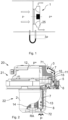
- FIG. 1 The pressure difference ⁇ p generated by a fan 1 through the fan wheel 25 during operation, as well as the intake-side negative pressure p- and the pressure-side, i.e., discharge-side positive pressure p+, are shown schematically by way of example.
- the negative pressure p- is used to generate an intake of a cooling air flow which, as a compensating flow, runs counter to the main flow direction of the air flow generated by the fan wheel 25.
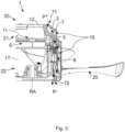
- FIG 2 shows a first embodiment of a partially cutaway external rotor motor 20 of the fan 1 in an axial fan design.
- the overall arrangement of the external rotor motor 20 is axially divided into the electronics section 21 and the immediately axially adjacent motor section 22.
- the motor electronics 11 are accommodated in the cover-shaped electronics housing 12
- in the motor section 22 are the components for driving the fan wheel 25 (not shown here, but mounted on the rotor 2 in a manner as shown in Figure 3
- the motor drive components responsible for the rotor are arranged, in particular the cylindrical rotor 2 with its pot-shaped rotor housing 13 (rotor bell) and the stator package 8 with motor windings accommodated therein.
- the bearing 14 of the motor shaft can also be seen.
- the inlet opening 71 for the cooling air flow 7 is provided on the front side of the electronics housing 12, wherein axially and radially extending cooling fins 3 are provided starting from the inlet opening and determine sectionally channel wall surfaces of the cooling channel 10.
- the cooling duct 10 is continuous and runs in the radially outer part of the external rotor motor. Following the inlet opening 71, it is deflected radially outwards past the electronic components arranged on a circuit board 15, which determine the motor electronics 11, and is then deflected radially inwards again to the rotor 2. In the area of the rotor 2, the cooling duct 10 runs axially straight within the rotor housing 13, directly along the stator core 8 and the bearing 14, up to the axially frontal outlet opening 72.
- the cooling duct in the embodiment shown is not specially walled, so that the cooling air flow can flow freely along the path of least resistance along the motor components to the outlet opening 72.
- a cooling duct with a special guide along certain components can be provided, which is formed as a closed duct by defined boundaries, for example the inner wall surface of the rotor housing.
- the motor section 22 stator cooling fins 5 arranged in a circumferential direction in the direction of the rotor 2.
- the cooling channel 10 runs past the stator cooling fins 5, so that the cooling air flow 7 carries away the heat absorbed by the stator cooling fins 5.
- the transition to the rotor 2 is closed by the cover 6, which is attached to the electronics housing 12 and has a labyrinth seal-like design in order to minimize pressure loss.
- the cover 6 forms, in sections, both a channel wall surface of the cooling channel 10 and an outer surface of the external rotor motor 20.
- the cooling air flow 7 is sucked in at the suction-side outlet opening 72 in the motor section 22, so that it flows on the pressure side into the inlet opening 71 and through the entire arrangement of the external rotor motor 20 to the outlet opening 72. Since the cooling air flow 7 is generated exclusively by the pressure difference between the suction side and the pressure side, it is referred to here as passive.
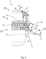
- FIG 3 An embodiment of the fan 1 in an alternative design as an axial fan is shown in a side view.
- the external rotor 20 of Figure 1 The features described are also present here, unless stated otherwise.
- the fan wheel 25 is attached to the rotor 2 with its impeller hub, completely enclosing the rotor housing 13. During operation, the fan wheel 25 generates not only the main flow but also the pressure difference ⁇ p used for the cooling air flow 7. In this embodiment, however, the outlet opening 72 is not provided on the rotor housing 13, but rather on the fan wheel 25 or the impeller hub.
- the cooling air flow 7 runs radially in the motor section 22 between the rotor housing 13 and the impeller hub 17 of the fan wheel 25, so that the cooling channel 10 in the motor section 22 is formed by the rotor housing 13 and the impeller hub of the fan wheel 25.
- FIG 4 An embodiment of the fan 1 is shown in a design as a radial fan, wherein the cooling channel 10, in contrast to the previous examples, is not guided along the entire rotor 2.
- the fan wheel 25 of the radial fan has the outlet opening in its impeller base plate 26 72.
- the impeller base plate 26 supports the impeller blades 9, which are backward-curved in the present embodiment.
- the cooling channel 10 thus runs from the inlet opening 71 in the electronics housing 12 along the cooling fins 3 to the motor section 22 and therein along the stator cooling fins 5 radially outward to the outlet opening 72 on the impeller base plate 26.
- the cooling air flow 7 is then conveyed radially outward by the fan wheel 25.
- the cooling in the electronics section 21 is identical to the previous embodiments. In the motor section 22, cooling occurs primarily via the stator cooling fins 5.
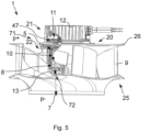
- FIG. 5 An alternative embodiment of the fan 1 is shown in a design as a radial fan with the external rotor motor 20, which, as in the previous embodiments, comprises the motor section 22 and the electronics section 21 axially adjacent along the rotation axis RA with the motor electronics 11 arranged therein. All identical features described in the above embodiments are not repeated again, but also apply to the embodiment according to Figure 5 .
- the electronics section can also be aligned radially to the rotation axis RA.
- the fan wheel 25 is mounted radially on the outside of the rotor 2.
- the fan 1 generates a pressure difference ⁇ p between its suction side and its pressure side via the fan wheel 25.
- the continuous cooling duct 10 runs from the pressure-side inlet opening 71 to the suction-side outlet opening 72 along the stator cooling fins 5, wherein during operation the cooling air flow 7, represented by arrows, through the cooling duct 10 is generated exclusively passively by the pressure difference ⁇ p generated by the fan wheel 25.
- the power module 47 of the motor electronics 11 generates the most heat and is therefore arranged directly adjacent to the stator bushing having the stator cooling fins 5 in order to cool the motor section 22 and the power module 47 of the motor electronics 11 via the stator bushing.
- FIG 6 another embodiment of the fan 1 is shown, wherein The structure is similar to that of Figure 5
- the cooling air flow 7 is the same as in the version according to Figure 4 outside the rotor 2.
- the fan wheel 25 of the fan also has the outlet opening 72 in its impeller base plate 26 carrying the backward-curved impeller blades 9.
- the cooling channel 10 runs from the radial outside along the stator cooling fins 5 to the outlet opening 72 on the impeller base plate 26.
- the cooling air flow 7 is then conveyed radially outwards through the fan wheel 25.
- the fan 1 generates, as in the embodiment according to Figure 5 via the fan wheel 25, the pressure difference ⁇ p between its suction side and its pressure side.
- the cooling air flow 7, indicated by arrows, through the cooling channel 10 is generated exclusively passively by the pressure difference ⁇ p generated by the fan wheel 25.
- the power module 47 of the motor electronics 11 is also arranged in this embodiment directly adjacent to the stator bushing having the stator cooling fins 5 in order to cool the motor section 22 and the power module 47 of the motor electronics 11 directly via the stator bushing. Also in the fan 1 according to Figure 6 The electronics section can be aligned or positioned radially to the rotation axis RA instead of axially.
Landscapes
- Engineering & Computer Science (AREA)
- Mechanical Engineering (AREA)
- General Engineering & Computer Science (AREA)
- Physics & Mathematics (AREA)
- Thermal Sciences (AREA)
- Power Engineering (AREA)
- Motor Or Generator Cooling System (AREA)
Description
- Die Erfindung betrifft einen Ventilator mit einem Außenläufermotor sowie einem Kühlkanal zur Kühlung sowohl der Motorelektronik als auch von Motorantriebskomponenten.
- Die Wärmeentwicklung bei Elektromotoren spielt eine entscheidende Rolle bei der abrufbaren Leistung und Lebensdauer. Deshalb werden bereits im Stand der Technik Maßnahmen zur Kühlung der Motorelektronik vorgesehen, insbesondere wird in einer Variante neben dem durch den Außenläufermotor anzutreibenden Ventilatorrad ein Aktivkühlrad am Rotor verbaut, welches während der Rotation des Rotors einen eigenen Kühlluftstrom erzeugt, der aktiv entlang der Motorelektronik vorbeigeführt wird. Wenn Außenläufermotoren bei geringen Drehzahlen eingesetzt werden reicht die Kühlleistung durch das Aktivkühlrad häufig nicht aus, um einen ausreichenden Wärmeabtransport zu gewährleisten. Zudem ist bei Aktivkühlrädern nachteilig, dass sie bei hohen Drehzahlen Geräusche erzeugen, drehrichtungsabhängig sein können und zusätzlichen Drehmomentbedarf aufweisen, welcher den Wirkungsgrad verschlechtert.
- Andere Lösungen sehen beispielsweise eine Vergrößerung der Oberfläche der angrenzenden Bauteile oder die Erhöhung des Materialaufwands, d.h. Vergrößerung der Wandstärke des Elektronikgehäuses, um mehr Wärme aufnehmen zu können, vor. Hierdurch steigt jedoch das Gewicht. Alternativ werden Materialien mit höherer Wärmeleitfähigkeit eingesetzt, die jedoch teurer sind.
- Neben der Kühlung der Motorelektronik ist auch eine Kühlung von Motorantriebskomponenten, beispielsweise des Rotors, Stators oder der Motorlagerung gewünscht.
- Druckschriftlicher Stand der Technik im vorliegenden technischen Gebiet ist beispielsweise in den Dokumenten
US 2017/288507 A1 ,WO 02/27895 A1 WO 2008/146154 A2 ,DE 10 2010 046 672 A1 ,US 6,107,708 A offenbart. - Der Erfindung liegt deshalb die Aufgabe zugrunde, einen Ventilator bereit zu stellen, der auch bei geringen Drehzahlen eine verbesserte Kühlung der Gesamtanordnung des Außenläufermotors bezüglich seiner Motorelektronik und Motorantriebskomponenten bei möglichst geringem und kostengünstigem Materialaufwand aufweist. Zudem soll die Geräuschentwicklung vergleichsweise gering sein.
- Diese Aufgabe wird durch die Merkmalskombination gemäß Patentanspruch 1 gelöst.
- Erfindungsgemäß wird ein Ventilator mit einem Außenläufermotor vorgeschlagen, wobei der Außenläufermotor einen in einem Motorabschnitt um eine Rotationsachse rotierenden Rotor aufweist, der ausgebildet ist zur radial außenseitig umschließenden Aufnahme eines Ventilatorrades. Der Außenläufermotor sieht ferner eine in einem Elektronikabschnitt angeordnete Motorelektronik aufgenommen in einem Elektronikgehäuse vor, wobei der Motorabschnitt und der Elektronikabschnitt entlang der Rotationsachse vorzugsweise axial, alternativ radial, angrenzend zueinander angeordnet sind. Der Ventilator erzeugt über das Ventilatorrad im bestimmungsgemäßen Betrieb einen Druckunterschied zwischen seiner vorzugsweise dem Rotor zugeordneten Saugseite und seiner vorzugsweise der Motorelektronik zugeordneten Druckseite. Innerhalb des Außenläufermotors verläuft ein durchgängiger Kühlkanal von einer druckseitigen Einströmöffnung an dem Elektronikgehäuse entlang der Motorelektronik und zumindest abschnittsweise entlang des Rotors bis zu einer saugseitigen Ausströmöffnung im Motorabschnitt, so dass im Betrieb ein Kühlluftstrom durch den Kühlkanal ausschließlich passiv durch den von dem Ventilatorrad erzeugten Druckunterschied erzeugbar ist, um sowohl den Elektronikabschnitt als auch den Motorabschnitt zu kühlen.
- Grundsätzlich gilt, dass die Druckseite und Saugseite von der Strömungsrichtung des Ventilators abhängen. Der Kühlluftstrom erfolgt jedoch stets von der Druckseite zur Saugseite. Die vorstehend beschriebene Einströmöffnung an dem Elektronikgehäuse ist bei einer inversen Strömungsrichtung dann die Ausströmöffnung, die Ausströmöffnung im Motorabschnitt wird dann zur Einströmöffnung.
- Im Betrieb des Ventilators saugt das Ventilatorrad auf der Saugseite Luft an, so dass saugseitig ein Unterdruck entsteht, und bläst diese auf der Druckseite aus, wo ein Überdruck entsteht. Hieraus ergibt sich eine Druckdifferenz Δp zwischen der Saugseite und der Druckseite. Durch die Druckdifferenz bildet sich eine Ausgleichsströmung durch den Kühlkanal, welche genutzt wird als passiver Kühlluftstrom. Bei der vorliegenden Lösung wird somit der Kühlluftstrom saugseitig an der Ausströmöffnung angesogen und durch den Kühlkanal gefördert, wobei die Druckdifferenz durch das Ventilatorrad auf der Ansaugseite des Ventilators erzeugt wird. Durch die Ansaugung des Kühlluftstromes auf der Druckseite und die Ausströmung des Kühlluftstromes auf der Saugseite am Rotor erfolgt eine ganzheitliche Kühlung sowohl der Motorelektronik im Elektronikabschnitt als auch der Motorantriebskomponenten im Motorabschnitt, d.h. der Gesamtanordnung des Außenläufermotors mit seinen Motorteilen und seiner Elektronik. Durch die Kühlung kann somit entweder die Leistung gesteigert oder je nach Anwendung sogar ein kleinerer Motor verbaut werden. Das spart Kosten.
- Als "passiv" erzeugter Kühlluftstrom durch den Kühlkanal ist vorliegend die Abgrenzung zu einem durch ein im Betrieb rotierendes Aktivkühlrad erzeugten und mithin aktiven Luftstrom definiert. Aktivkühlräder erzeugen Geräusche, insbesondere bei höheren Drehzahlen. Dies kann durch die rein passive Kühlung verhindert werden.
- Als Abgrenzung zwischen dem Elektronikabschnitt und dem Motorabschnitt dient ein Axialschnitt, bei dem die am weitesten in Richtung Rotor vorstehenden Komponenten der Motorelektronik enden. Häufig wird die Motorelektronik auch axial auf die Motorantriebskomponenten aufgesetzt. Dann ergibt sich die Trennung durch die beiden Bauteile.
- Zur Verbesserung der Kühlleistung sieht eine Ausführungsvariante vor, dass an dem Elektronikgehäuse mehrere Kühlrippen ausgebildet sind, die sich axial und radial ausgehend von der Einströmöffnung in den Kühlkanal erstrecken und eine Kanalwandfläche des Kühlkanals bilden. Die Kühlrippen bilden zudem vorzugsweise die Einströmöffnung an dem Elektronikgehäuse. Die über die Kühlrippen erreichte Oberflächenvergrößerung und die Positionierung unmittelbar an der Einströmöffnung führen zu einer günstigen und effektiven Wärmeabfuhr über den Kühlluftstrom durch den Kühlkanal.
- Der Ventilator ist ferner vorzugsweise dadurch gekennzeichnet, dass der Rotor ein Rotorgehäuse, vorzugsweise ausgebildet als Rotorglocke, aufweist und die Ausströmöffnung im Bereich einer axialen Stirnseite des Rotorgehäuses ausgebildet ist. Die Ausströmung erfolgt mithin vorzugsweise axial, kann jedoch auch an der Mantelfläche des Rotorgehäuses oder am Übergang zwischen der axialen Stirnfläche und der Mantelfläche vorgesehen werden und somit eine zumindest teilweise radiale Abströmrichtung aufweisen.
- Bei Radialventilatoren sind häufig keine Öffnungen am Rotor bzw. Rotorgehäuse vorgesehen. Deshalb weist das Ventilatorrad für diese Ausführung eine Laufradbodenscheibe mit daran ausgebildeten Laufradschaufeln auf, wobei die Ausströmöffnung in der Laufradbodenscheibe ausgebildet ist. Der Kühlkanal erstreckt sich somit im Motorabschnitt nicht über die gesamte axiale Länge, sondern wird bereits an der Laufradbodenscheibe nach außerhalb des Rotors gleitet.
- Erfindungsgemäß weist der Außenläufermotor im Motorabschnitt eine Statorbuchse mit einem Statorpaket und Motorwicklungen sowie in Umfangsrichtung verteilt angeordnete Statorkühlrippen auf, wobei der Kühlkanal auch entlang der Statorkühlrippen verläuft.
- Bei der Lösung für Radialventilatoren ist dabei insbesondere vorgesehen, dass die Laufradbodenscheibe axial an die sich axial zur Laufradbodenscheibe erstreckenden Statorkühlrippen angrenzend verläuft, so dass der Kühlluftstrom axial über die Statorkühlrippen zur Ausströmöffnung in der Laufradbodenscheibe führbar ist. Bei dieser Lösung wird auch für Radialventilatoren neben der Kühlung der Motorelektronik im Elektronikabschnitt eine ausreichende Kühlleistung im Motorabschnitt gewährleistet, da die Statorkühlrippen als Motorkomponente im Motorabschnitt angeordnet sind.
- Bei den Axialventilatoren und Diagonalventilatoren sieht eine erfindungsgemäße Ausführungsvariante vor, dass der Außenläufermotor im Motorabschnitt eine Statorbuchse mit einem Statorpaket und Motorwicklungen sowie in Umfangsrichtung verteilt angeordnete Statorkühlrippen aufweist, wobei der Kühlluftstrom unmittelbar angrenzend entlang der Statorkühlrippen und entlang dem Statorpaket verläuft. Der Kühlluftstrom kann dabei frei durch den Motorabschnitt den Weg des geringsten Widerstands nehmend strömen oder in einem Kühlkanal an bestimmten Bauteilen entlang geführt werden. Durch die Möglichkeit, die Ausströmöffnung am Rotor bzw. Rotorgehäuse selbst auszubilden, kann der Kühlluftstrom im Inneren des Rotors direkt an den sich im Betrieb erwärmenden Bauteilen entlang geführt werden.
- Ein günstiges Ausführungsbeispiel des Ventilators ist dadurch gekennzeichnet, dass der Kühlkanal in einem Übergang von dem Elektronikabschnitt zu dem Motorabschnitt durch eine stehende oder rotierbare Abdeckung geschlossen oder im Wesentlichen geschlossen ist. Im Wesentlichen geschlossen bedeutet, dass keine vollständige Abdichtung vorgesehen ist. Die Abdeckung kann jedoch labyrinthförmig im Sinne einer Labyrinthdichtung ausgebildet sein, um möglichst geringe Leckageverluste hinnehmen zu müssen. Je nachdem, an welchem Bauteil die Abdeckung befestigt wird, beispielsweise dem Elektronikgehäuse oder dem Rotor, steht oder rotiert sie im Betrieb. Die Abdeckung bildet dabei eine Außenmantelfläche des Außenläufermotors.
- In eine Weiterbildung des Ventilators sieht vor, dass der Kühlkanal im Verlauf von der Einströmöffnung zur Ausströmöffnung mehrere Richtungsänderungen aufweist, so dass der Kühlluftstrom mehrfach umgelenkt wird. Hierdurch kann die Kühlung entlang der zu kühlenden Bauteile gelenkt und somit die Kühlleistung vergrößert werden.
- Die Ausströmöffnung an dem Rotorgehäuse ist gegenüber dem Ventilatorrad axial beabstandet. Dies fördert, dass ein ausreichender Druckunterschied und mithin der Saugeffekt an der Ausströmöffnung gewährleistet ist.
- Ferner sieht eine Ausführung des Ventilators vor, dass der Kühlkanal in Umfangsrichtung lokal begrenzt in dem Elektronikabschnitt und dem Motorabschnitt verläuft. Der Platzbedarf für die Kühlung ist hierdurch beschränkt. Der Aufbau des Außenläufermotors bleibt kompakt.
- In einer Weiterbildung des Ventilators ist der Rotor über mindestens ein Lager gelagert, wobei der Kühlkanal an dem mindestens einem Lager vorbeigeführt wird. Auch die Lagerung erzeugt im Betrieb Wärme, die vorzugsweise durch den Kühlluftstrom mit abgeführt wird.
- Die Offenbarung umfasst zudem eine Ausführung des Ventilators mit einem Außenläufermotor mit einem in einem Motorabschnitt um eine Rotationsachse rotierenden Rotor ausgebildet zur radial außenseitig umschließenden Aufnahme eines Ventilatorrades und mit einer in einem Elektronikabschnitt angeordneten Motorelektronik. Der Motorabschnitt und der Elektronikabschnitt sind entlang der Rotationsachse axial oder gegenüber der Rotationsachse radial angrenzend zueinander angeordnet. Der Außenläufermotor weist im Motorabschnitt eine Statorbuchse mit einem Statorpaket und Motorwicklungen sowie in Umfangsrichtung verteilt angeordnete Statorkühlrippen auf. Der Ventilator erzeugt über das Ventilatorrad im bestimmungsgemäßen Betrieb einen Druckunterschied Δp zwischen seiner Saugseite und seiner Druckseite, wobei innerhalb des Außenläufermotors ein durchgängiger Kühlkanal von einer druckseitigen Einströmöffnung bis zu einer saugseitigen Ausströmöffnung entlang der Statorkühlrippen verläuft. Im Betrieb ist ein Kühlluftstrom durch den Kühlkanal ausschließlich passiv durch den von dem Ventilatorrad erzeugten Druckunterschied (Δp) erzeugbar. Dabei ist vorgesehen, dass zumindest ein Leistungsmodul der Motorelektronik unmittelbar an die die Statorkühlrippen aufweisende Statorbuchse angrenzend angeordnet ist, um den Motorabschnitt und zumindest das Leistungsmodul, aber auch weitere Bauteile der Motorelektronik über die Statorbuchse zu entwärmen bzw. zu kühlen.
- Alle vorstehend beschriebenen Merkmale sind unmittelbar auch für diesen Ventilator anwendbar, soweit dies technisch möglich ist. Insbesondere ist der Kühlluftstrom ebenfalls richtungsabhängig von der Strömungsrichtung des Ventilators. Auch sind wieder beide Varianten umfasst, nämlich die Durchströmung durch die Strömungsöffnung in der Laufradbodenscheibe und mithin der Verlauf des Kühlluftstromes außerhalb des Rotorgehäuses (Rotorglocke) oder die Durchströmung der Strömungsöffnung an der Stirnseite der Rotorglocke und mithin der Verlauf des Kühlluftstromes innerhalb der Rotorglocke entlang der Motorbauteile wie beispielsweise den Statorwicklungen.
- Andere vorteilhafte Weiterbildungen der Erfindung sind in den Unteransprüchen gekennzeichnet bzw. werden nachstehend zusammen mit der Beschreibung der bevorzugten Ausführung der Erfindung anhand der Figuren näher dargestellt. Es zeigen:
- Fig. 1
- eine schematische Ansicht zum durch den Ventilator erzeugten Druckunterschied,
- Fig. 2
- ein erstes Ausführungsbeispiel des Außenläufermotors in einer Ausführung für einen Axial-, Radial- und Diagonalventilator,
- Fig. 3
- ein Ausführungsbeispiel des Ventilators in einer Ausführung als Axialventilator,
- Fig. 4
- ein Ausführungsbeispiel des Ventilators in einer Ausführung als Radialventilator,
- Fig. 5
- ein alternatives Ausführungsbeispiel des Ventilators in einer ersten Variante, das nicht Teil der Erfindung ist,
- Fig. 6
- das Ausführungsbeispiel des Ventilators gemäß
Figur 5 in einer weiteren Variante, das nicht Teil der Erfindung ist. - In
Figur 1 ist beispielhaft schematisch der von einem Ventilator 1 durch das Ventilatorrad 25 im Betrieb erzeugt Druckunterschied Δp sowie der ansaugseitige Unterdruck p- und druckseitige, d. h. ausströmseitige Überdruck p+ dargestellt. Vorliegend wird der Unterdruck p- genutzt, um eine Ansaugung eines Kühlluftstroms zu erzeugen, der als Ausgleichsströmung entgegen der Hauptströmungsrichtung des durch das Ventilatorrad 25 erzeugten Luftstromes läuft. -
Figur 2 zeigt ein erstes Ausführungsbeispiel eines teilweise aufgeschnittenen Außenläufermotors 20 des Ventilators 1 in einer Ausführung als Axialventilator. Die Gesamtanordnung des Außenläufermotors 20 ist axial unterteilt in den Elektronikabschnitt 21 und den unmittelbar axial angrenzenden Motorabschnitt 22. Im Elektronikabschnitt 21 ist die Motorelektronik 11 in dem deckelförmigen Elektronikgehäuse 12 aufgenommen, im Motorabschnitt 22 sind die für den Antrieb des Ventilatorrads 25 (hier nicht gezeigt, jedoch auf den Rotor 2 in einer Weise aufgesetzt, wie inFigur 3 dargestellt) zuständigen Motorantriebskomponenten angeordnet, insbesondere der zylindrische Rotor 2 mit seinem topfförmigen Rotorgehäuse 13 (Rotorglocke) und den darin aufgenommenen Statorpaket 8 mit Motorwicklungen. Auch zu erkennen ist die Lagerung 14 der Motorwelle. - An dem Elektronikgehäuse 12 ist stirnseitig die Einströmöffnung 71 für den Kühlluftstrom 7 vorgesehen, wobei sich ausgehend von der Einströmöffnung axial und radial erstreckende Kühlrippen 3 vorgesehen sind und abschnittsweise Kanalwandflächen des Kühlkanals 10 bestimmen. Der Kühlkanal 10 ist durchgängig und verläuft im radial äußeren Teil des Außenläufermotors, wird im Anschluss an die Einströmöffnung 71 nach radial außen umgelenkt vorbei an den auf einer Leiterplatte 15 angeordneten Elektronikbauteilen, welche die Motorelektronik 11 bestimmen, und wieder nach radial innen umgelenkt zu dem Rotor 2. Im Bereich des Rotors 2 verläuft der Kühlkanal 10 axial geradlinig innerhalb des Rotorgehäuses 13 unmittelbar entlang dem Statorpaket 8 und dem Lager 14 bis zur axial stirnseitigen Ausströmöffnung 72. Im Bereich des Rotors 2 ist der Kühlkanal in der gezeigten Ausführung nicht speziell bewandet, so dass der Kühlluftstrom frei entlang dem Weg des geringsten Widerstands entlang der Motorkomponenten zur Ausströmöffnung 72 strömen kann. Es kann jedoch alternativ ein Kühlkanal mit spezieller Führung entlang bestimmter Bauteile vorgesehen werden, der durch festgelegte Begrenzungen, beispielsweise die Innenwandfläche des Rotorgehäuses, als geschlossener Kanal gebildet wird.
- Im an den Elektronikabschnitt 21 angrenzenden Bereich erstrecken sich im Motorabschnitt 22 in Umfangsrichtung verteilt angeordnete Statorkühlrippen 5 in Richtung des Rotors 2. Der Kühlkanal 10 verläuft an den Statorkühlrippen 5 vorbei, so dass der Kühlluftstrom 7 die von den Statorkühlrippen 5 aufgenommene Wärme abtransportiert. Der Übergang zum Rotor 2 ist durch die Abdeckung 6 geschlossen, die am Elektronikgehäuse 12 befestigt ist und eine labyrinthdichtungsartige Ausbildung aufweist, um den Druckverlust zu minimieren. Die Abdeckung 6 bildet abschnittsweise sowohl eine Kanalwandfläche des Kühlkanals 10 als auch eine äußere Mantelfläche des Außenläufermotors 20. Im Betrieb wird der Kühlluftstrom 7 an der saugseitigen Ausströmöffnung 72 im Motorabschnitt 22 angesaugt, so dass er druckseitig in die Einströmöffnung 71 und durch die Gesamtanordnung des Außenläufermotors 20 hindurch bis zur Ausströmöffnung 72 strömt. Da der Kühlluftstrom 7 ausschließlich durch den Druckunterschied zwischen der Saugseite und der Druckseite erzeugt wird, wird er vorliegend als passiv bezeichnet.
- In
Figur 3 ist ein Ausführungsbeispiel des Ventilators 1 in einer alternativen Ausführung als Axialventilator in einer Seitenansicht dargestellt. Die zum Außenläufer 20 ausFigur 1 beschriebenen Merkmale liegen hier ebenfalls vor, soweit nicht anders erläutert. An dem Rotor 2 ist das Ventilatorrad 25 mit seiner Laufradnabe das Rotorgehäuse 13 vollständig umschließend befestigt. Das Ventilatorrad 25 erzeugt im Betrieb neben der Hauptströmung auch den für den Kühlluftstrom 7 genutzten Druckunterschied Δp. Die Ausströmöffnung 72 in dieser Ausführung jedoch nicht am Rotorgehäuse 13, sondern am Ventilatorrad 25 bzw. der Laufradnabe vorgesehen. Der Kühlluftstrom 7 verläuft im Motorabschnitt 22 radial zwischen dem Rotorgehäuse 13 und der Laufradnabe 17 des Ventilatorrads 25, so dass der Kühlkanal 10 im Motorabschnitt 22 durch das Rotorgehäuse 13 und die Laufradnabe des Ventilatorrads 25 gebildet ist. - In
Figur 4 ist ein Ausführungsbeispiel des Ventilators 1 in einer Ausführung als Radialventilator dargestellt, wobei der Kühlkanal 10 im Unterschied zu den vorherigen Beispielen nicht entlang des gesamten Rotors 2 geführt wird. Das Ventilatorrad 25 des Radialventilators weist in seiner Laufradbodenscheibe 26 die Ausströmöffnung 72 auf. Die Laufradbodenscheibe 26 trägt die Laufradschaufeln 9, welche in der vorliegenden Ausführung rückwärtsgekrümmt sind. Der Kühlkanal 10 verläuft mithin von der Einströmöffnung 71 im Elektronikgehäuse 12 entlang der Kühlrippen 3 zum Motorabschnitt 22 und darin entlang der Statorkühlrippen 5 nach radial außen zur Ausströmöffnung 72 an der Laufradbodenscheibe 26. Der Kühlluftstrom 7 wird dann durch das Ventilatorrad 25 nach radial außen weg gefördert. Die Kühlung im Elektronikabschnitt 21 ist identisch zu den vorherigen Ausführungsbeispielen. Im Motorabschnitt 22 erfolgt die Kühlung hauptsächlich über die Statorkühlrippen 5. - In
Figur 5 ist eine Alternative Ausführung des Ventilators 1 in einer Ausführung als Radialventilator mit dem Außenläufermotor 20 dargestellt, der wie in den vorigen Ausführungsbeispielen den Motorabschnitt 22 und den entlang der Rotationsachse RA axial angrenzenden Elektronikabschnitt 21 mit der darin angeordneten Motorelektronik 11 umfasst. Alle zu den vorstehenden Ausführungen beschriebenen identischen Merkmale werden nicht nochmals wiederholt, gelten jedoch auch für das Ausführungsbeispiel nachFigur 5 . In einer nicht gezeigten alternativen Ausführung kann der Elektronikabschnitt auch radial zur Rotationsachse RA ausgerichtet sein. Am Rotor 2 ist radial außenseitig das Ventilatorrad 25 aufgenommen. Der Ventilator 1 erzeugt über das Ventilatorrad 25 einen Druckunterschied Δp zwischen seiner Saugseite und seiner Druckseite. Innerhalb des Außenläufermotors 20 verläuft der durchgängige Kühlkanal 10 von der druckseitigen Einströmöffnung 71 bis zu der saugseitigen Ausströmöffnung 72 entlang der Statorkühlrippen 5, wobei im Betrieb der durch Pfeile dargestellte Kühlluftstrom 7 durch den Kühlkanal 10 ausschließlich passiv durch den von dem Ventilatorrad 25 erzeugten Druckunterschied Δp erzeugt wird. - Das Leistungsmodul 47 der Motorelektronik 11 erzeugt die meiste Wärme und ist deshalb unmittelbar an die die Statorkühlrippen 5 aufweisende Statorbuchse angrenzend angeordnet, um den Motorabschnitt 22 und das Leistungsmodul 47 der Motorelektronik 11 über die Statorbuchse zu kühlen.
- In
Figur 6 ist ein weiteres Ausführungsbeispiel des Ventilators 1 dargestellt, wobei der Aufbau bis auf die folgenden Unterschiede demjenigen ausFigur 5 entspricht. Der Kühlluftstrom 7 beliebt wie bei der Ausführung gemäßFigur 4 außerhalb des Rotors 2. Auch in dieser Ausführung weist das Ventilatorrad 25 des Ventilators in seiner die rückwärtsgekrümmten Laufradschaufeln 9 tragenden Laufradbodenscheibe 26 die Ausströmöffnung 72 auf. Der Kühlkanal 10 verläuft von radial außen entlang der Statorkühlrippen 5 zur Ausströmöffnung 72 an der Laufradbodenscheibe 26. Der Kühlluftstrom 7 wird anschließend durch das Ventilatorrad 25 nach radial außen gefördert. Der Ventilator 1 erzeugt wie bei der Ausführung gemäßFigur 5 über das Ventilatorrad 25 den Druckunterschied Δp zwischen seiner Saugseite und seiner Druckseite. Im Betrieb wird der durch Pfeile dargestellte Kühlluftstrom 7 durch den Kühlkanal 10 ausschließlich passiv durch den von dem Ventilatorrad 25 erzeugten Druckunterschied Δp erzeugt. Das Leistungsmodul 47 der Motorelektronik 11 ist auch bei dieser Ausführung unmittelbar an die die Statorkühlrippen 5 aufweisende Statorbuchse angrenzend angeordnet, um den Motorabschnitt 22 und das Leistungsmodul 47 der Motorelektronik 11 unmittelbar über die Statorbuchse zu kühlen. Auch bei dem Ventilator 1 gemäßFigur 6 kann der Elektronikabschnitt anstelle axial auch radial zur Rotationsachse RA ausgerichtet bzw. positioniert sein.
Claims (12)
- Ventilator mit einem Außenläufermotor (20) umfassend einen in einem Motorabschnitt (22) um eine Rotationsachse (RA) rotierenden Rotor (2) ausgebildet zur radial außenseitig umschließenden Aufnahme eines Ventilatorrades (25), und eine in einem Elektronikabschnitt (21) angeordnete Motorelektronik (11) aufgenommen in einem Elektronikgehäuse (12), wobei der Motorabschnitt (22) und der Elektronikabschnitt (21) entlang der Rotationsachse (RA) axial oder radial angrenzend zueinander angeordnet sind, wobei der Ventilator (1) über das Ventilatorrad (25) im bestimmungsgemäßen Betrieb einen Druckunterschied (Δp) zwischen seiner Saugseite und seiner Druckseite erzeugt, wobei innerhalb des Außenläufermotors (20) ein durchgängiger Kühlkanal (10) von einer Strömungsöffnung an dem Elektronikgehäuse (12) entlang der Motorelektronik (11) und zumindest abschnittsweise entlang des Rotors (2) bis zu einer Strömungsöffnung im Motorabschnitt (22) verläuft und im Betrieb ein Kühlluftstrom (7) durch den Kühlkanal (10) ausschließlich passiv durch den von dem Ventilatorrad (25) erzeugten Druckunterschied (Δp) erzeugbar ist, um sowohl den Elektronikabschnitt (21) als auch den Motorabschnitt (22) zu kühlen, dadurch gekennzeichnet, dass der Außenläufermotor (20) im Motorabschnitt (22) eine Statorbuchse mit einem Statorpaket (8) und Motorwicklungen sowie in Umfangsrichtung verteilt angeordnete Statorkühlrippen (5) aufweist, wobei der Kühlkanal (10) entweder entlang der Statorkühlrippen (5) oder entlang der Statorkühlrippen (5) und entlang dem Statorpaket (8) verläuft.
- Ventilator nach Anspruch 1, dadurch gekennzeichnet, dass die Strömungsöffnung an dem Elektronikgehäuse eine druckseitige Einströmöffnung (71) und die Strömungsöffnung im Motorabschnitt (22) eine saugseitige Ausströmöffnung (72) bestimmen.
- Ventilator nach Anspruch 2, dadurch gekennzeichnet, dass an dem Elektronikgehäuse (12) mehrere Kühlrippen (3) ausgebildet sind, die sich axial und radial ausgehend von der Einströmöffnung (71) in den Kühlkanal (10) erstrecken und eine Kanalwandfläche des Kühlkanals (10) bilden.
- Ventilator nach Anspruch 2 oder 3, dadurch gekennzeichnet, dass der Rotor (2) ein Rotorgehäuse (13) aufweist und die Ausströmöffnung (72) im Bereich einer axialen Stirnseite des Rotorgehäuses (13) ausgebildet ist.
- Ventilator nach Anspruch 2 oder 3, dadurch gekennzeichnet, dass das Ventilatorrad (25) eine Laufradbodenscheibe (26) mit daran ausgebildeten Laufradschaufeln (9) aufweist, in der die Ausströmöffnung (72) ausgebildet ist.
- Ventilator nach dem vorigen Anspruch, dadurch gekennzeichnet, dass die Laufradbodenscheibe (26) axial an die sich axial zur Laufradbodenscheibe (26) erstreckenden Statorkühlrippen (5) angrenzend verläuft, so dass der Kühlluftstrom (7) axial über die Statorkühlrippen (5) zur Ausströmöffnung (72) in der Laufradbodenscheibe (26) führbar ist.
- Ventilator nach einem der vorigen Ansprüche, dadurch gekennzeichnet, dass der Kühlkanal (10) in einem Übergang von dem Elektronikabschnitt (21) zu dem Motorabschnitt (22) durch eine stehende oder rotierbare unbeschaufelte Abdeckung (6) geschlossen oder im Wesentlichen geschlossen ist.
- Ventilator nach einem der vorigen Ansprüche, dadurch gekennzeichnet, dass der Kühlkanal (10) im Verlauf von der Einströmöffnung (71) zur Ausströmöffnung (72) mehrere Richtungsänderungen aufweist, so dass der Kühlluftstrom (7) mehrfach umgelenkt wird.
- Ventilator nach einem der vorigen Ansprüche, dadurch gekennzeichnet, dass die Ausströmöffnung (72) an dem Rotor (2) gegenüber dem Ventilatorrad (25) axial beabstandet ist.
- Ventilator nach einem der vorigen Ansprüche, dadurch gekennzeichnet, dass der Kühlkanal (10) in Umfangsrichtung lokal begrenzt in dem Elektronikabschnitt (21) und dem Motorabschnitt (22) verläuft.
- Ventilator nach einem der vorigen Ansprüche, dadurch gekennzeichnet, dass der Rotor (2) über mindestens ein Lager (14) gelagert ist und der Kühlkanal (10) an dem mindestens einem Lager (14) vorbeiführt.
- Ventilator nach einem der vorigen Ansprüche, dadurch gekennzeichnet, dass der Rotor (2) der Saugseite und die Motorelektronik (11) der Druckseite zugeordnet sind.
Priority Applications (1)
| Application Number | Priority Date | Filing Date | Title |
|---|---|---|---|
| EP22152257.6A EP4006348B1 (de) | 2020-01-16 | 2021-01-12 | Ventilator mit einem aussenläufermotor und kühlkanal zur kühlung der motorelektronik und von motorantriebskomponenten |
Applications Claiming Priority (1)
| Application Number | Priority Date | Filing Date | Title |
|---|---|---|---|
| DE102020100865.1A DE102020100865A1 (de) | 2020-01-16 | 2020-01-16 | Ventilator mit einem Außenläufermotor und Kühlkanal zur Kühlung der Motorelektronik und von Motorantriebskomponenten |
Related Child Applications (2)
| Application Number | Title | Priority Date | Filing Date |
|---|---|---|---|
| EP22152257.6A Division-Into EP4006348B1 (de) | 2020-01-16 | 2021-01-12 | Ventilator mit einem aussenläufermotor und kühlkanal zur kühlung der motorelektronik und von motorantriebskomponenten |
| EP22152257.6A Division EP4006348B1 (de) | 2020-01-16 | 2021-01-12 | Ventilator mit einem aussenläufermotor und kühlkanal zur kühlung der motorelektronik und von motorantriebskomponenten |
Publications (2)
| Publication Number | Publication Date |
|---|---|
| EP3851679A1 EP3851679A1 (de) | 2021-07-21 |
| EP3851679B1 true EP3851679B1 (de) | 2025-04-09 |
Family
ID=74175610
Family Applications (2)
| Application Number | Title | Priority Date | Filing Date |
|---|---|---|---|
| EP22152257.6A Active EP4006348B1 (de) | 2020-01-16 | 2021-01-12 | Ventilator mit einem aussenläufermotor und kühlkanal zur kühlung der motorelektronik und von motorantriebskomponenten |
| EP21151059.9A Active EP3851679B1 (de) | 2020-01-16 | 2021-01-12 | Ventilator mit einem aussenläufermotor und kühlkanal zur kühlung der motorelektronik und von motorantriebskomponenten |
Family Applications Before (1)
| Application Number | Title | Priority Date | Filing Date |
|---|---|---|---|
| EP22152257.6A Active EP4006348B1 (de) | 2020-01-16 | 2021-01-12 | Ventilator mit einem aussenläufermotor und kühlkanal zur kühlung der motorelektronik und von motorantriebskomponenten |
Country Status (4)
| Country | Link |
|---|---|
| US (1) | US11680584B2 (de) |
| EP (2) | EP4006348B1 (de) |
| CN (1) | CN113141089B (de) |
| DE (1) | DE102020100865A1 (de) |
Families Citing this family (1)
| Publication number | Priority date | Publication date | Assignee | Title |
|---|---|---|---|---|
| CN119765794B (zh) * | 2024-12-17 | 2025-08-26 | 安徽致钲电驱动技术有限公司 | 一种高效散热集成式电机 |
Citations (19)
| Publication number | Priority date | Publication date | Assignee | Title |
|---|---|---|---|---|
| US227895A (en) | 1880-05-25 | Chaeles a | ||
| US5818133A (en) | 1996-04-19 | 1998-10-06 | Siemens Canada Ltd. | Brushless motor with tubular bearing support |
| US5944497A (en) | 1997-11-25 | 1999-08-31 | Siemens Canada Limited | Fan assembly having an air directing member to cool a motor |
| US6107708A (en) | 1998-03-16 | 2000-08-22 | Asmo, Co., Ltd. | Brushless motor |
| WO2002027895A1 (en) | 2000-09-27 | 2002-04-04 | Zexel Valeo Climate Control Corporation | Brushless motor |
| US20050067500A1 (en) | 2003-09-30 | 2005-03-31 | Valeo Electrical Systems, Inc. | Fan hub assembly for effective motor cooling |
| EP1454400B1 (de) | 2001-12-14 | 2006-05-03 | Conti Temic microelectronic GmbH | Elektrische antriebseinheit |
| WO2008061502A1 (de) | 2006-11-24 | 2008-05-29 | Temic Automotive Electric Motors Gmbh | Axiallüfter für einen fahrzeugkühler |
| WO2008146154A2 (en) | 2007-05-30 | 2008-12-04 | Spal Automotive S.R.L. | Ventilation unit |
| EP2369183A1 (de) | 2010-03-22 | 2011-09-28 | ebm-papst Mulfingen GmbH & Co. KG | Ventilator |
| DE102010046672A1 (de) | 2010-09-27 | 2012-03-29 | Valeo Klimasysteme Gmbh | Fahrzeuglüfter und Belüftungsanlage |
| DE102011053611A1 (de) | 2011-09-14 | 2013-03-14 | Ebm-Papst Mulfingen Gmbh & Co. Kg | Rotierende elektrische Maschine |
| DE102013109577A1 (de) | 2012-09-05 | 2014-03-06 | Johnson Electric S.A. | Gebläsemodul für einen Wärmetauscher |
| US20140265664A1 (en) | 2013-03-15 | 2014-09-18 | Regal Beloit Australia Pty Ltd. | Air-cooled electric machine and method of assembling the same |
| US20160079824A1 (en) | 2014-09-15 | 2016-03-17 | Regal Beloit America, Inc. | Air-cooled electric machine and method of assembling the same |
| DE202016102350U1 (de) | 2016-05-03 | 2016-06-06 | Ebm-Papst Mulfingen Gmbh & Co. Kg | Motoraufnahmevorrichtung |
| DE102015105188A1 (de) | 2015-04-02 | 2016-10-06 | Ebm-Papst Mulfingen Gmbh & Co. Kg | Elektromotor mit drückender Kühlluftförderung sowie Verfahren zum Kühlen von Bauteilen des Elektromotors |
| US9531239B2 (en) | 2012-08-02 | 2016-12-27 | Ebm-Papst Mulfingen Gmbh & Co. Kg | Active cooling of a motor having an integrated cooling channel |
| US20170288507A1 (en) | 2016-03-31 | 2017-10-05 | Asmo Co., Ltd. | Fan motor |
Family Cites Families (9)
| Publication number | Priority date | Publication date | Assignee | Title |
|---|---|---|---|---|
| IT1240997B (it) * | 1990-10-30 | 1993-12-27 | Magneti Marelli Spa | Motoventilatore, particolarmente per autoveicoli |
| FR2710371B1 (fr) * | 1993-09-24 | 1995-12-22 | Ecia Equip Composants Ind Auto | Groupe motoventilateur à moyeu perfectionné. |
| IT1308475B1 (it) * | 1999-05-07 | 2001-12-17 | Gate Spa | Motoventilatore, particolarmente per uno scambiatore di calore di unautoveicolo |
| FR2795458B1 (fr) * | 1999-06-24 | 2002-06-14 | Jeumont Ind | Motoventilateur de mise en circulation d'un fluide dans une installation d'echange thermique et procede de refroidissement du moteur d'entrainement du motoventilateur |
| CN1223306C (zh) * | 2002-05-31 | 2005-10-19 | 乐金电子(天津)电器有限公司 | 吸尘器用离心送风装置 |
| EP1621773B1 (de) | 2004-07-30 | 2013-04-17 | Brose Fahrzeugteile GmbH & Co. KG, Würzburg | Kühlgebläse mit Elektromotor |
| DE102014112821A1 (de) * | 2014-09-05 | 2016-03-10 | Ebm-Papst Mulfingen Gmbh & Co. Kg | Lüfter mit Leiterplattenkühlkreislauf |
| CN109149839A (zh) * | 2018-08-23 | 2019-01-04 | 浙江东欣节能科技有限公司 | 驱动装置 |
| DE102019101471A1 (de) * | 2019-01-22 | 2020-07-23 | Ebm-Papst Landshut Gmbh | Außenläufermotor mit Kühlrad |
-
2020
- 2020-01-16 DE DE102020100865.1A patent/DE102020100865A1/de active Pending
-
2021
- 2021-01-12 US US17/146,654 patent/US11680584B2/en active Active
- 2021-01-12 EP EP22152257.6A patent/EP4006348B1/de active Active
- 2021-01-12 EP EP21151059.9A patent/EP3851679B1/de active Active
- 2021-01-13 CN CN202110040237.2A patent/CN113141089B/zh active Active
Patent Citations (19)
| Publication number | Priority date | Publication date | Assignee | Title |
|---|---|---|---|---|
| US227895A (en) | 1880-05-25 | Chaeles a | ||
| US5818133A (en) | 1996-04-19 | 1998-10-06 | Siemens Canada Ltd. | Brushless motor with tubular bearing support |
| US5944497A (en) | 1997-11-25 | 1999-08-31 | Siemens Canada Limited | Fan assembly having an air directing member to cool a motor |
| US6107708A (en) | 1998-03-16 | 2000-08-22 | Asmo, Co., Ltd. | Brushless motor |
| WO2002027895A1 (en) | 2000-09-27 | 2002-04-04 | Zexel Valeo Climate Control Corporation | Brushless motor |
| EP1454400B1 (de) | 2001-12-14 | 2006-05-03 | Conti Temic microelectronic GmbH | Elektrische antriebseinheit |
| US20050067500A1 (en) | 2003-09-30 | 2005-03-31 | Valeo Electrical Systems, Inc. | Fan hub assembly for effective motor cooling |
| WO2008061502A1 (de) | 2006-11-24 | 2008-05-29 | Temic Automotive Electric Motors Gmbh | Axiallüfter für einen fahrzeugkühler |
| WO2008146154A2 (en) | 2007-05-30 | 2008-12-04 | Spal Automotive S.R.L. | Ventilation unit |
| EP2369183A1 (de) | 2010-03-22 | 2011-09-28 | ebm-papst Mulfingen GmbH & Co. KG | Ventilator |
| DE102010046672A1 (de) | 2010-09-27 | 2012-03-29 | Valeo Klimasysteme Gmbh | Fahrzeuglüfter und Belüftungsanlage |
| DE102011053611A1 (de) | 2011-09-14 | 2013-03-14 | Ebm-Papst Mulfingen Gmbh & Co. Kg | Rotierende elektrische Maschine |
| US9531239B2 (en) | 2012-08-02 | 2016-12-27 | Ebm-Papst Mulfingen Gmbh & Co. Kg | Active cooling of a motor having an integrated cooling channel |
| DE102013109577A1 (de) | 2012-09-05 | 2014-03-06 | Johnson Electric S.A. | Gebläsemodul für einen Wärmetauscher |
| US20140265664A1 (en) | 2013-03-15 | 2014-09-18 | Regal Beloit Australia Pty Ltd. | Air-cooled electric machine and method of assembling the same |
| US20160079824A1 (en) | 2014-09-15 | 2016-03-17 | Regal Beloit America, Inc. | Air-cooled electric machine and method of assembling the same |
| DE102015105188A1 (de) | 2015-04-02 | 2016-10-06 | Ebm-Papst Mulfingen Gmbh & Co. Kg | Elektromotor mit drückender Kühlluftförderung sowie Verfahren zum Kühlen von Bauteilen des Elektromotors |
| US20170288507A1 (en) | 2016-03-31 | 2017-10-05 | Asmo Co., Ltd. | Fan motor |
| DE202016102350U1 (de) | 2016-05-03 | 2016-06-06 | Ebm-Papst Mulfingen Gmbh & Co. Kg | Motoraufnahmevorrichtung |
Also Published As
| Publication number | Publication date |
|---|---|
| US20210222704A1 (en) | 2021-07-22 |
| US11680584B2 (en) | 2023-06-20 |
| EP4006348A1 (de) | 2022-06-01 |
| EP3851679A1 (de) | 2021-07-21 |
| CN113141089B (zh) | 2024-05-31 |
| EP4006348B1 (de) | 2024-08-07 |
| DE102020100865A1 (de) | 2021-07-22 |
| CN113141089A (zh) | 2021-07-20 |
Similar Documents
| Publication | Publication Date | Title |
|---|---|---|
| EP2880745B1 (de) | Aktive kühlung eines motors mit integriertem kühlkanal | |
| EP2691655B1 (de) | Diagonalventilator | |
| EP2880746B1 (de) | Aktive kühlung eines motors | |
| DE102016200081B4 (de) | Elektrische Maschine | |
| DE102008008300A1 (de) | Passiv-Lüfter | |
| WO2014056717A2 (de) | Kühlung für stirnräume einer geschlossenen elektrischen maschine | |
| EP3245715B1 (de) | Elektromotor mit verbesserter kühlung | |
| EP3729611B1 (de) | Rollenmotor mit geschlossenem kühlkreislauf | |
| EP3851679B1 (de) | Ventilator mit einem aussenläufermotor und kühlkanal zur kühlung der motorelektronik und von motorantriebskomponenten | |
| EP3278427B1 (de) | Elektromotor mit drückender kühlluftförderung sowie verfahren zum kühlen von bauteilen des elektromotors | |
| WO2022078816A1 (de) | Kreiselpumpe mit einem antrieb | |
| DE102017205687B4 (de) | Rotor für eine elektrische Maschine | |
| EP3513486A1 (de) | Elektromotor mit verbesserter motorkühlung zum antrieb eines lüfters | |
| EP4229741B1 (de) | Kreiselpumpe mit einem antrieb | |
| EP3844400A1 (de) | Rotormontageeinheit mit kühlfunktion | |
| EP4206474B1 (de) | Vakuumpumpe | |
| EP3161351B1 (de) | Antrieb | |
| EP3779208B1 (de) | Axial- oder radialventilator mit bypasskanal im elektronikgehäuse | |
| WO2023232660A1 (de) | Kühlrad zur aktiven kühlung eines stators eines elektromotors | |
| DE102022000354A1 (de) | Elektromotor, vorzugsweise Außenläufermotor, vorzugsweise zum Antreiben eines Turbomaschinenlaufrades, mit einem Kühllüfterrad, welches eine andere, vorteilhaft höhere Rotationsgeschwindigkeit hat als der Rotor des Motors | |
| DE102014009313A1 (de) | Antrieb | |
| DE102012025877B3 (de) | Aktive Kühlung eines Motors | |
| DE102023132548A1 (de) | Elektromotor mit Rotorlagerkühlung | |
| DE102016222260A1 (de) | Elektrische Maschine | |
| WO2026047587A1 (de) | Aussenläufermaschine, insbesondere aussenläufermotor oder aussenläufergenerator, mit einem rotor mit welle, die innen in einem statorturm des stators bzw. der statorbuchse gelagert ist, in welchem kühlkanäle ausgebildet sind, in denen ein fluid abwärme der maschine und insbesondere des stators und dessen elektromagnetischen systems aufnimmt und abführt |
Legal Events
| Date | Code | Title | Description |
|---|---|---|---|
| PUAI | Public reference made under article 153(3) epc to a published international application that has entered the european phase |
Free format text: ORIGINAL CODE: 0009012 |
|
| STAA | Information on the status of an ep patent application or granted ep patent |
Free format text: STATUS: THE APPLICATION HAS BEEN PUBLISHED |
|
| AK | Designated contracting states |
Kind code of ref document: A1 Designated state(s): AL AT BE BG CH CY CZ DE DK EE ES FI FR GB GR HR HU IE IS IT LI LT LU LV MC MK MT NL NO PL PT RO RS SE SI SK SM TR |
|
| STAA | Information on the status of an ep patent application or granted ep patent |
Free format text: STATUS: REQUEST FOR EXAMINATION WAS MADE |
|
| 17P | Request for examination filed |
Effective date: 20220117 |
|
| RBV | Designated contracting states (corrected) |
Designated state(s): AL AT BE BG CH CY CZ DE DK EE ES FI FR GB GR HR HU IE IS IT LI LT LU LV MC MK MT NL NO PL PT RO RS SE SI SK SM TR |
|
| STAA | Information on the status of an ep patent application or granted ep patent |
Free format text: STATUS: EXAMINATION IS IN PROGRESS |
|
| 17Q | First examination report despatched |
Effective date: 20230329 |
|
| GRAP | Despatch of communication of intention to grant a patent |
Free format text: ORIGINAL CODE: EPIDOSNIGR1 |
|
| STAA | Information on the status of an ep patent application or granted ep patent |
Free format text: STATUS: GRANT OF PATENT IS INTENDED |
|
| INTG | Intention to grant announced |
Effective date: 20241216 |
|
| GRAS | Grant fee paid |
Free format text: ORIGINAL CODE: EPIDOSNIGR3 |
|
| GRAA | (expected) grant |
Free format text: ORIGINAL CODE: 0009210 |
|
| STAA | Information on the status of an ep patent application or granted ep patent |
Free format text: STATUS: THE PATENT HAS BEEN GRANTED |
|
| P01 | Opt-out of the competence of the unified patent court (upc) registered |
Free format text: CASE NUMBER: APP_6006/2025 Effective date: 20250205 |
|
| AK | Designated contracting states |
Kind code of ref document: B1 Designated state(s): AL AT BE BG CH CY CZ DE DK EE ES FI FR GB GR HR HU IE IS IT LI LT LU LV MC MK MT NL NO PL PT RO RS SE SI SK SM TR |
|
| REG | Reference to a national code |
Ref country code: GB Ref legal event code: FG4D Free format text: NOT ENGLISH |
|
| REG | Reference to a national code |
Ref country code: CH Ref legal event code: EP |
|
| REG | Reference to a national code |
Ref country code: DE Ref legal event code: R096 Ref document number: 502021007134 Country of ref document: DE |
|
| REG | Reference to a national code |
Ref country code: IE Ref legal event code: FG4D Free format text: LANGUAGE OF EP DOCUMENT: GERMAN |
|
| REG | Reference to a national code |
Ref country code: NL Ref legal event code: MP Effective date: 20250409 |
|
| PG25 | Lapsed in a contracting state [announced via postgrant information from national office to epo] |
Ref country code: NL Free format text: LAPSE BECAUSE OF FAILURE TO SUBMIT A TRANSLATION OF THE DESCRIPTION OR TO PAY THE FEE WITHIN THE PRESCRIBED TIME-LIMIT Effective date: 20250409 |
|
| PG25 | Lapsed in a contracting state [announced via postgrant information from national office to epo] |
Ref country code: PT Free format text: LAPSE BECAUSE OF FAILURE TO SUBMIT A TRANSLATION OF THE DESCRIPTION OR TO PAY THE FEE WITHIN THE PRESCRIBED TIME-LIMIT Effective date: 20250811 Ref country code: ES Free format text: LAPSE BECAUSE OF FAILURE TO SUBMIT A TRANSLATION OF THE DESCRIPTION OR TO PAY THE FEE WITHIN THE PRESCRIBED TIME-LIMIT Effective date: 20250409 Ref country code: FI Free format text: LAPSE BECAUSE OF FAILURE TO SUBMIT A TRANSLATION OF THE DESCRIPTION OR TO PAY THE FEE WITHIN THE PRESCRIBED TIME-LIMIT Effective date: 20250409 |
|
| REG | Reference to a national code |
Ref country code: LT Ref legal event code: MG9D |
|
| PG25 | Lapsed in a contracting state [announced via postgrant information from national office to epo] |
Ref country code: GR Free format text: LAPSE BECAUSE OF FAILURE TO SUBMIT A TRANSLATION OF THE DESCRIPTION OR TO PAY THE FEE WITHIN THE PRESCRIBED TIME-LIMIT Effective date: 20250710 Ref country code: NO Free format text: LAPSE BECAUSE OF FAILURE TO SUBMIT A TRANSLATION OF THE DESCRIPTION OR TO PAY THE FEE WITHIN THE PRESCRIBED TIME-LIMIT Effective date: 20250709 |
|
| PG25 | Lapsed in a contracting state [announced via postgrant information from national office to epo] |
Ref country code: PL Free format text: LAPSE BECAUSE OF FAILURE TO SUBMIT A TRANSLATION OF THE DESCRIPTION OR TO PAY THE FEE WITHIN THE PRESCRIBED TIME-LIMIT Effective date: 20250409 |
|
| PG25 | Lapsed in a contracting state [announced via postgrant information from national office to epo] |
Ref country code: BG Free format text: LAPSE BECAUSE OF FAILURE TO SUBMIT A TRANSLATION OF THE DESCRIPTION OR TO PAY THE FEE WITHIN THE PRESCRIBED TIME-LIMIT Effective date: 20250409 |
|
| PG25 | Lapsed in a contracting state [announced via postgrant information from national office to epo] |
Ref country code: HR Free format text: LAPSE BECAUSE OF FAILURE TO SUBMIT A TRANSLATION OF THE DESCRIPTION OR TO PAY THE FEE WITHIN THE PRESCRIBED TIME-LIMIT Effective date: 20250409 |
|
| PG25 | Lapsed in a contracting state [announced via postgrant information from national office to epo] |
Ref country code: RS Free format text: LAPSE BECAUSE OF FAILURE TO SUBMIT A TRANSLATION OF THE DESCRIPTION OR TO PAY THE FEE WITHIN THE PRESCRIBED TIME-LIMIT Effective date: 20250709 |
|
| PG25 | Lapsed in a contracting state [announced via postgrant information from national office to epo] |
Ref country code: IS Free format text: LAPSE BECAUSE OF FAILURE TO SUBMIT A TRANSLATION OF THE DESCRIPTION OR TO PAY THE FEE WITHIN THE PRESCRIBED TIME-LIMIT Effective date: 20250809 |
|
| PG25 | Lapsed in a contracting state [announced via postgrant information from national office to epo] |
Ref country code: LV Free format text: LAPSE BECAUSE OF FAILURE TO SUBMIT A TRANSLATION OF THE DESCRIPTION OR TO PAY THE FEE WITHIN THE PRESCRIBED TIME-LIMIT Effective date: 20250409 |
|
| REG | Reference to a national code |
Ref country code: DE Ref legal event code: R026 Ref document number: 502021007134 Country of ref document: DE |
|
| PG25 | Lapsed in a contracting state [announced via postgrant information from national office to epo] |
Ref country code: SM Free format text: LAPSE BECAUSE OF FAILURE TO SUBMIT A TRANSLATION OF THE DESCRIPTION OR TO PAY THE FEE WITHIN THE PRESCRIBED TIME-LIMIT Effective date: 20250409 Ref country code: DK Free format text: LAPSE BECAUSE OF FAILURE TO SUBMIT A TRANSLATION OF THE DESCRIPTION OR TO PAY THE FEE WITHIN THE PRESCRIBED TIME-LIMIT Effective date: 20250409 |
|
| PLBI | Opposition filed |
Free format text: ORIGINAL CODE: 0009260 |
|
| PG25 | Lapsed in a contracting state [announced via postgrant information from national office to epo] |
Ref country code: CZ Free format text: LAPSE BECAUSE OF FAILURE TO SUBMIT A TRANSLATION OF THE DESCRIPTION OR TO PAY THE FEE WITHIN THE PRESCRIBED TIME-LIMIT Effective date: 20250409 |
|
| PLAX | Notice of opposition and request to file observation + time limit sent |
Free format text: ORIGINAL CODE: EPIDOSNOBS2 |
|
| REG | Reference to a national code |
Ref country code: CH Ref legal event code: L10 Free format text: ST27 STATUS EVENT CODE: U-0-0-L10-L00 (AS PROVIDED BY THE NATIONAL OFFICE) Effective date: 20260121 |
|
| PG25 | Lapsed in a contracting state [announced via postgrant information from national office to epo] |
Ref country code: EE Free format text: LAPSE BECAUSE OF FAILURE TO SUBMIT A TRANSLATION OF THE DESCRIPTION OR TO PAY THE FEE WITHIN THE PRESCRIBED TIME-LIMIT Effective date: 20250409 |
|
| PG25 | Lapsed in a contracting state [announced via postgrant information from national office to epo] |
Ref country code: RO Free format text: LAPSE BECAUSE OF FAILURE TO SUBMIT A TRANSLATION OF THE DESCRIPTION OR TO PAY THE FEE WITHIN THE PRESCRIBED TIME-LIMIT Effective date: 20250409 Ref country code: SK Free format text: LAPSE BECAUSE OF FAILURE TO SUBMIT A TRANSLATION OF THE DESCRIPTION OR TO PAY THE FEE WITHIN THE PRESCRIBED TIME-LIMIT Effective date: 20250409 |
|
| 26 | Opposition filed |
Opponent name: ZIEHL-ABEGG SE Effective date: 20260108 |