EP3851634A1 - Seal element for sealing a joint between a rotor blade and a rotor disk of a turbine engine - Google Patents
Seal element for sealing a joint between a rotor blade and a rotor disk of a turbine engine Download PDFInfo
- Publication number
- EP3851634A1 EP3851634A1 EP20208865.4A EP20208865A EP3851634A1 EP 3851634 A1 EP3851634 A1 EP 3851634A1 EP 20208865 A EP20208865 A EP 20208865A EP 3851634 A1 EP3851634 A1 EP 3851634A1
- Authority
- EP
- European Patent Office
- Prior art keywords
- seal element
- rotor
- platform
- seal
- lug
- Prior art date
- Legal status (The legal status is an assumption and is not a legal conclusion. Google has not performed a legal analysis and makes no representation as to the accuracy of the status listed.)
- Granted
Links
Images









Classifications
-
- F—MECHANICAL ENGINEERING; LIGHTING; HEATING; WEAPONS; BLASTING
- F01—MACHINES OR ENGINES IN GENERAL; ENGINE PLANTS IN GENERAL; STEAM ENGINES
- F01D—NON-POSITIVE DISPLACEMENT MACHINES OR ENGINES, e.g. STEAM TURBINES
- F01D5/00—Blades; Blade-carrying members; Heating, heat-insulating, cooling or antivibration means on the blades or the members
- F01D5/30—Fixing blades to rotors; Blade roots ; Blade spacers
-
- F—MECHANICAL ENGINEERING; LIGHTING; HEATING; WEAPONS; BLASTING
- F01—MACHINES OR ENGINES IN GENERAL; ENGINE PLANTS IN GENERAL; STEAM ENGINES
- F01D—NON-POSITIVE DISPLACEMENT MACHINES OR ENGINES, e.g. STEAM TURBINES
- F01D11/00—Preventing or minimising internal leakage of working-fluid, e.g. between stages
- F01D11/005—Sealing means between non relatively rotating elements
- F01D11/006—Sealing the gap between rotor blades or blades and rotor
-
- F—MECHANICAL ENGINEERING; LIGHTING; HEATING; WEAPONS; BLASTING
- F01—MACHINES OR ENGINES IN GENERAL; ENGINE PLANTS IN GENERAL; STEAM ENGINES
- F01D—NON-POSITIVE DISPLACEMENT MACHINES OR ENGINES, e.g. STEAM TURBINES
- F01D5/00—Blades; Blade-carrying members; Heating, heat-insulating, cooling or antivibration means on the blades or the members
- F01D5/30—Fixing blades to rotors; Blade roots ; Blade spacers
- F01D5/3007—Fixing blades to rotors; Blade roots ; Blade spacers of axial insertion type
-
- F—MECHANICAL ENGINEERING; LIGHTING; HEATING; WEAPONS; BLASTING
- F04—POSITIVE - DISPLACEMENT MACHINES FOR LIQUIDS; PUMPS FOR LIQUIDS OR ELASTIC FLUIDS
- F04D—NON-POSITIVE-DISPLACEMENT PUMPS
- F04D29/00—Details, component parts, or accessories
- F04D29/08—Sealings
- F04D29/083—Sealings especially adapted for elastic fluid pumps
-
- F—MECHANICAL ENGINEERING; LIGHTING; HEATING; WEAPONS; BLASTING
- F04—POSITIVE - DISPLACEMENT MACHINES FOR LIQUIDS; PUMPS FOR LIQUIDS OR ELASTIC FLUIDS
- F04D—NON-POSITIVE-DISPLACEMENT PUMPS
- F04D29/00—Details, component parts, or accessories
- F04D29/08—Sealings
- F04D29/16—Sealings between pressure and suction sides
- F04D29/161—Sealings between pressure and suction sides especially adapted for elastic fluid pumps
- F04D29/164—Sealings between pressure and suction sides especially adapted for elastic fluid pumps of an axial flow wheel
-
- F—MECHANICAL ENGINEERING; LIGHTING; HEATING; WEAPONS; BLASTING
- F04—POSITIVE - DISPLACEMENT MACHINES FOR LIQUIDS; PUMPS FOR LIQUIDS OR ELASTIC FLUIDS
- F04D—NON-POSITIVE-DISPLACEMENT PUMPS
- F04D29/00—Details, component parts, or accessories
- F04D29/26—Rotors specially for elastic fluids
- F04D29/32—Rotors specially for elastic fluids for axial flow pumps
- F04D29/321—Rotors specially for elastic fluids for axial flow pumps for axial flow compressors
- F04D29/322—Blade mountings
-
- F—MECHANICAL ENGINEERING; LIGHTING; HEATING; WEAPONS; BLASTING
- F05—INDEXING SCHEMES RELATING TO ENGINES OR PUMPS IN VARIOUS SUBCLASSES OF CLASSES F01-F04
- F05D—INDEXING SCHEME FOR ASPECTS RELATING TO NON-POSITIVE-DISPLACEMENT MACHINES OR ENGINES, GAS-TURBINES OR JET-PROPULSION PLANTS
- F05D2240/00—Components
- F05D2240/20—Rotors
- F05D2240/30—Characteristics of rotor blades, i.e. of any element transforming dynamic fluid energy to or from rotational energy and being attached to a rotor
-
- F—MECHANICAL ENGINEERING; LIGHTING; HEATING; WEAPONS; BLASTING
- F05—INDEXING SCHEMES RELATING TO ENGINES OR PUMPS IN VARIOUS SUBCLASSES OF CLASSES F01-F04
- F05D—INDEXING SCHEME FOR ASPECTS RELATING TO NON-POSITIVE-DISPLACEMENT MACHINES OR ENGINES, GAS-TURBINES OR JET-PROPULSION PLANTS
- F05D2240/00—Components
- F05D2240/55—Seals
-
- F—MECHANICAL ENGINEERING; LIGHTING; HEATING; WEAPONS; BLASTING
- F05—INDEXING SCHEMES RELATING TO ENGINES OR PUMPS IN VARIOUS SUBCLASSES OF CLASSES F01-F04
- F05D—INDEXING SCHEME FOR ASPECTS RELATING TO NON-POSITIVE-DISPLACEMENT MACHINES OR ENGINES, GAS-TURBINES OR JET-PROPULSION PLANTS
- F05D2240/00—Components
- F05D2240/80—Platforms for stationary or moving blades
-
- F—MECHANICAL ENGINEERING; LIGHTING; HEATING; WEAPONS; BLASTING
- F05—INDEXING SCHEMES RELATING TO ENGINES OR PUMPS IN VARIOUS SUBCLASSES OF CLASSES F01-F04
- F05D—INDEXING SCHEME FOR ASPECTS RELATING TO NON-POSITIVE-DISPLACEMENT MACHINES OR ENGINES, GAS-TURBINES OR JET-PROPULSION PLANTS
- F05D2300/00—Materials; Properties thereof
- F05D2300/60—Properties or characteristics given to material by treatment or manufacturing
- F05D2300/601—Fabrics
-
- F—MECHANICAL ENGINEERING; LIGHTING; HEATING; WEAPONS; BLASTING
- F05—INDEXING SCHEMES RELATING TO ENGINES OR PUMPS IN VARIOUS SUBCLASSES OF CLASSES F01-F04
- F05D—INDEXING SCHEME FOR ASPECTS RELATING TO NON-POSITIVE-DISPLACEMENT MACHINES OR ENGINES, GAS-TURBINES OR JET-PROPULSION PLANTS
- F05D2300/00—Materials; Properties thereof
- F05D2300/60—Properties or characteristics given to material by treatment or manufacturing
- F05D2300/603—Composites; e.g. fibre-reinforced
- F05D2300/6033—Ceramic matrix composites [CMC]
-
- Y—GENERAL TAGGING OF NEW TECHNOLOGICAL DEVELOPMENTS; GENERAL TAGGING OF CROSS-SECTIONAL TECHNOLOGIES SPANNING OVER SEVERAL SECTIONS OF THE IPC; TECHNICAL SUBJECTS COVERED BY FORMER USPC CROSS-REFERENCE ART COLLECTIONS [XRACs] AND DIGESTS
- Y02—TECHNOLOGIES OR APPLICATIONS FOR MITIGATION OR ADAPTATION AGAINST CLIMATE CHANGE
- Y02T—CLIMATE CHANGE MITIGATION TECHNOLOGIES RELATED TO TRANSPORTATION
- Y02T50/00—Aeronautics or air transport
- Y02T50/60—Efficient propulsion technologies, e.g. for aircraft
Definitions
- This disclosure relates generally to rotational equipment and, more particularly, to sealing a joint between a rotor blade and a rotor disk.
- a rotor assembly for a gas turbine engine may include a plurality of rotor blades arranged around a rotor disk. Each rotor blade may be mounted to the rotor disk by a mechanical joint such as, for example, a dovetail interface. A component such as a damper may also be arranged between a lug of the rotor disk and the rotor blade to dampen vibrations induced during rotation of the rotor assembly. While various types and configurations of rotor assemblies are known in the art, there is still room in the art for improvement. In particular, there is need in the art for reducing fluid leakage through mechanical joints between rotor blades and a rotor disk.
- a rotor assembly for a piece of rotational equipment.
- This rotor assembly includes a rotor disk, a rotor blade and a seal element.
- the rotor disk is configured to rotate about a rotational axis.
- the rotor blade includes an airfoil, a platform and a mount attaching the rotor blade to the rotor disk.
- the seal element is seated in a groove of the rotor disk. The seal element is configured to sealingly engage the platform and the mount.
- a rotor assembly for a turbine engine.
- This rotor assembly includes a rotor disk, a rotor blade and a seal element.
- the rotor disk is configured to rotate about a rotational axis.
- the rotor disk includes a first lug, a second lug and a slot laterally between and formed by the first lug and the second lug.
- the rotor blade includes an airfoil, a platform and a mount seated within the slot.
- the seal element is configured to at least partially seal a gap between the first lug and the platform.
- the seal element is also configured to at least partially seal a gap between the first lug and the mount.
- this rotor assembly includes a rotor disk, a rotor blade and a seal element.
- the rotor disk is configured to rotate about a rotational axis.
- the rotor disk includes a first lug, a second lug and a slot laterally between and formed by the first lug and the second lug.
- the rotor blade includes an airfoil, a platform and a mount seated within the slot.
- the seal element extends laterally along the first lug.
- the seal element is located radially between the rotor disk and the platform.
- the seal element is configured as a rope seal element, a wire seal element or a polymer seal element.
- the mount may include a root and a neck.
- the seal element may be configured to sealingly engage the neck.
- the seal element may be configured to: radially abut against the platform; and laterally abut against the mount.
- the rotor disk may include a lug and a slot partially formed by the lug.
- the mount may be seated within the slot.
- the seal element may extend laterally across the lug.
- the seal element may follow a longitudinal centerline. A portion of the longitudinal centerline may extend along and may be parallel with the mount.
- the seal element may be configured as or otherwise include an elongated seal element that follows a longitudinal centerline with a tortuous trajectory.
- the seal element may be configured as or otherwise include an elongated seal element.
- a first length of the elongated seal element may follow a first trajectory.
- a second length of the elongated seal element may follow a second trajectory that is angularly offset from the first trajectory.
- a platform seal may be included.
- the platform seal may be configured to sealingly engage the platform and retain the seal element within the groove.
- the seal element may be wrapped around the platform seal.
- the seal element may be configured as or otherwise include a rope seal element.
- the seal element may be configured as or otherwise include a wire seal element.
- the seal element may be configured from or otherwise include polymeric material.
- the seal element may be configured from or otherwise include sheet metal.
- An inner surface of the platform may extend radially inwards as the inner surface extends from a lateral distal edge of the platform to the mount.
- a lug surface of the rotor disk may follow the inner surface.
- the rotor blade may be configured as or otherwise include a compressor blade.
- the seal element may be configured as an elongated compliant seal element.
- At least a portion of the seal element may extend laterally along an inner surface of the platform.
- a second portion of the seal element may extend axially along the mount.
- the present disclosure may include any one or more of the individual features disclosed above and/or below alone or in any combination thereof.
- FIG. 1 illustrates a bladed rotor assembly 30 for a piece of rotational equipment.
- An example of such a piece of rotational equipment is a gas turbine engine for an aircraft propulsion system, an exemplary embodiment of which is described below in further detail with respect to FIG. 22 .
- the rotor assembly 30 of the present disclosure is not limited to such an aircraft application nor a gas turbine engine application.
- the rotor assembly 30, for example, may alternatively be configured with rotational equipment such as an industrial gas turbine engine, a wind turbine, a water turbine or any other apparatus which includes a bladed rotor.
- the rotor assembly 30 of FIG. 1 includes a rotor disk 32 and a plurality of rotor blades 34; e.g., compressor blades.
- the rotor disk 32 of FIG. 1 is configured to rotate about a rotational axis 36, which may also be an axial centerline of the rotor assembly 30 and/or the piece of rotational equipment.
- the rotor disk 32 includes a rim 38 at a radial outer periphery of the rotor disk 32.
- This rim 38 includes a rim base 40 and a plurality of rim lugs 42.
- the rim base 40 extends circumferentially about (e.g., completely around) the rotational axis 36. Referring to FIG. 3 , the rim base 40 extends axially along the rotational axis 36 between a first (e.g., forward and/or upstream) end 44 of the rim 38 and a second (e.g., aft and/or downstream) end 46 of the rim 38.
- the rim lugs 42 of FIG. 2 are arranged circumferentially about the rim base 40 and the rotational axis 36 in an annular array. Each of the rim lugs 42 projects radially out, in an outward direction relative to the rotational axis 36, from an outer periphery of the rim base 40 a respective distal lug end surface 48. Each of the rim lugs 42 extends laterally (e.g., in a circumferential or tangential direction relative to the rotational axis 36) between opposing lug first and second side surfaces 50A and 50B (generally referred to as "50"). Referring to FIG. 3 , each of the rim lugs 42 extends (e.g., substantially) axially along the rotational axis 36 between the rim first end 44 and the rim second end 46.
- the rim lugs 42 are circumferentially spaced about (e.g., completely around) the rotational axis 36 so as to form an annular array of mount slots 52.
- Each of the mount slots 52 is disposed laterally between and formed by a circumferentially adjacent / neighboring pair of the rim lugs 42 and their side surfaces 50.
- Each mount slot 52 extends radially inward into the rotor disk 32 from respective distal lug end surfaces 48 to a respective slot end surface 54; e.g., a slot bottom surface.
- Each mount slot 52 extends laterally between a respective one of the lug first side surfaces 50A and a respective one of the lug second side surfaces 50B.
- Each mount slot 52 may extend (e.g., substantially) axially through (or axially into) the rotor disk 32 as shown, for example, in FIG. 3 .
- each rotor blade 34 includes a rotor blade airfoil 56, a rotor blade platform 58 and a rotor blade mount 60.
- the rotor blade airfoil 56 projects radially out from the rotor blade platform 58 in a spanwise direction to a (e.g., unshrouded) airfoil tip 62.
- the rotor blade airfoil 56 includes an airfoil first (e.g., pressure and/or concave) side surface 64 and an airfoil second (e.g., suction and/or convex) side surface 66.
- first and second side surfaces 64 and 66 extend along a chord line of the airfoil 56 between and meet at an airfoil (e.g., forward and/or upstream) leading edge 68 and an airfoil (e.g., aft and/or downstream) trailing edge 70.
- the rotor blade platform 58 of FIG. 4 is radially between and connected to the rotor blade airfoil 56 and the rotor blade mount 60.
- the rotor blade platform 58 is configured to form a portion of an inner peripheral boarder of a gas path 72 (e.g., a core gas path) extending axially across the rotor assembly 30; e.g., a gas path into which the rotor blade airfoils 56 radially extend.
- a gas path 72 e.g., a core gas path
- outer platform surface 74 that extends axially along the rotational axis 36 between a platform first (e.g., forward and/or upstream) edge 76 and a platform second (e.g., aft and/or downstream) edge 78.
- the outer platform surface 74 extends circumferentially between opposing platform first and second side edges 80A and 80B (generally referred to as "80").
- the rotor blade platform 58 is configured with a platform first side segment 82A (e.g., a side projection and/or wing) and a platform second side segment 82B (e.g., a side projection and/or wing), which segments 82A and 82B are generally referred to as "82".
- the platform first side segment 82A projects circumferentially away from the airfoil 56 and the mount 60 to the first side edge 80A. This platform first side segment 82A is thereby cantilevered from the mount 60.
- the platform first side segment 82A extends radially between the outer platform surface 74 and a first segment of an inner platform surface 84.
- the platform second side segment 82B projects circumferentially away from the airfoil 56 and the mount 60 to the second side edge 80B. This platform second side segment 82B is thereby cantilevered from the mount 60.
- the platform second side segment 82B extends radially between the outer platform surface 74 and a second segment of inner platform surface 84.
- the rotor blade mount 60 of FIG. 4 includes a mount neck 86 and a mount root 88.
- the mount neck 86 extends radially between and is connected to the rotor blade platform 58 and the mount root 88.
- the mount neck 86 extends laterally between opposing neck first and second side surfaces 90A and 90B (generally referred to as "90").
- the mount neck 86 extends (e.g., substantially) axially along the rotational axis 36 between a first (e.g., forward and/or upstream) end 92 of the mount 60 and a second (e.g., aft and/or downstream) end 94 of the mount 60.
- the mount root 88 extends (e.g., substantially) axially along the rotational axis 36 between the mount first end 92 and the mount second end 94.
- the mount root 88 of FIG. 4 flares laterally out from the mount neck 86 so as to form, for example, a dovetail attachment.
- the present disclosure is not limited to such an exemplary attachment configuration.
- the mount root 88 projects radially inward from the mount neck 86 to a mount distal end surface 96; e.g., a mount bottom surface.
- the rotor blades 34 are arranged circumferentially around the rotor disk 32 and the rotational axis 36 in an annular array.
- Each of the rotor blades 34 is attached to the rotor disk 32 via a mechanical joint; e.g., a dovetail interface.
- the rotor blade mount 60 of each rotor blade 34 for example, is mated with (e.g., slide into and seated within) a respective one of the mount slots 52 in the rotor disk 32.
- the rotor blade mounts 60 may be axially secured within the mount slots 52 using one or more retainers 98 and 100 (e.g., retaining rings) respectively seated in retainer slots 102 and 104 in the rim base 40.
- retainers 98 and 100 e.g., retaining rings
- the present disclosure is not limited to the foregoing exemplary retainer configuration.
- fluid e.g., compressed air
- fluid may leak across the rotor assembly 30.
- the fluid may leak axially through radial gaps between the rim lugs 42 and the rotor blade platforms 58.
- Fluid may also or alternatively leak axially through lateral gaps between the rim lugs 42 and the rotor blade mounts 60.
- Fluid may still also or alternatively leak radially through lateral gaps between the platform edges 80.
- Such leakage may reduce performance of the rotational equipment. Therefore, to reduce and/or prevent such fluid leakage across the rotor assembly 30, the rotor assembly 30 of the present disclosure further includes a seal assembly 106, examples of which are shown in FIGS. 9-21 .
- the seal assembly 106 of FIGS. 9 and 10 includes a plurality of seal component pairs 108, an exemplary one of which is shown.
- Each seal component pair 108 includes a platform seal 110 and a seal element 112.
- the platform seal 110 includes a platform seal base 114 (e.g., a base plate) and one or more seal element locators 116A, 116B and 116C (generally referred to as "116") (e.g., projections, pedestals, etc.).
- the platform seal base 114 extends (e.g., substantially) axially along the rotational axis 36 between a seal base first (e.g., forward and/or upstream) end 118 and a seal base second (e.g., aft and/or downstream) end 120.
- the platform seal base 114 extends laterally (e.g., circumferentially) between opposing seal base first and second sides 122A and 122B (generally referred to as "122").
- the platform seal base 114 extends vertically (e.g., radially) between a platform seal inner surface 124 (see FIG. 9 ) and a platform seal outer surface 126 (see FIG. 10 ).
- the element locators 116 are connected to the platform seal base 114. Each of the element locators 116 projects vertically out from the platform seal base 114 and its platform seal inner surface 124 to a respective distal locator end 128A, 128B, 128C (generally referred to as "128").
- the element locators 116 are arranged laterally along the platform seal inner surface 124.
- the first element locator 116A is disposed at (e.g., on, adjacent or proximate) the seal base first side 122A.
- the second element locator 116B is disposed at the seal base second side 122B.
- the third element locator 116C is disposed laterally between the first and the second element locators 116A and 116B; e.g., laterally centered on the platform seal inner surface 124.
- the platform seal 110 of FIG. 9 is configured with a plurality of grooves 129A and 129B (generally referred to as "129") and a rim shelf 130.
- the first groove 129A is formed laterally between the first element locator 116A and the third element locator 116C.
- the second groove 129B is formed laterally between the second element locator 116B and the third element locator 116C.
- the rim shelf 130 extends (e.g., completely, or partially) around an outer perimeter of the platform seal 110; e.g., see dashed line in FIGS. 9 and 10 .
- the rim shelf 130 may only extend along a portion of the outer perimeter of the platform seal 110; e.g., partially or completely along one or each of the ends 118 and 120 and/or partially or completely along one or each of the sides 122.
- the platform seal 110 may be configured without the rim shelf 130.
- Each platform seal 110 may be configured as a monolithic body.
- the term "monolithic” may describe a single unitary body formed without severable components.
- each platform seal 110 may be laid up, cast, machined and/or otherwise formed from a single body of material.
- each platform seal 110 may be formed from a plurality of discretely formed segments which are subsequently permanently bonded together; e.g., welded, adhered, etc.
- non-monolithic may described a body formed from a plurality of discretely formed bodies that are severable; e.g., may be disassembly from one another.
- the present disclosure is not limited to monolithic platform seals.
- the platform seal 110 is formed from platform seal material.
- the platform seal material may include, but are not limited to, metal, polymeric material and ceramic material.
- the metal include, but are not limited to, aluminum (Al), nickel (Ni), titanium (Ti), and alloys of any one or more of the foregoing.
- the polymetric material may include, but are not limited to, fiber-reinforced thermoplastic material and fiber-reinforced thermoset material.
- An example of the ceramic material is, but is not limited to, ceramic matrix composite (CMC) material.
- the seal element 112 of FIG. 11 (shown in a relaxed and/or non-assembled state) is configured as an elongated seal element.
- This seal element 112 for example, has a relatively small cross-sectional width 132 (e.g., diameter) and a relatively long longitudinal length 134.
- This longitudinal length 134 may be measured along a longitudinal centerline 136 of the seal element 112 between opposing ends 138A and 138B (generally referred to as "138") of the seal element 112.
- the longitudinal length 134 may be at least four times (4x), ten times (10x), fifteen times (15x), twenty times (20x), or more the cross-sectional width 137; e.g., the length 134 may be between 10x and 30x the width 137.
- the longitudinal length 134 may be sized such that the seal element 112 covers one or more or each of the gaps between the elements 90, 84, 42, 110; see FIGS. 16 and 17 .
- the longitudinal length 134 may also be sized such that the seal element 112 engages the locators 116 in order to retain seal element 112 in place during operation.
- the seal element 112 may have a circular cross-sectional geometry when viewed, for example, in a plane perpendicular to the longitudinal centerline 136.
- the present disclosure is not limited to such an exemplary seal element cross-sectional geometry.
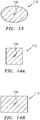
- the seal element 112 may be configured with a non-circular cross-sectional geometry. Examples of non-circular cross-sectional geometries include, but are not limited to, an oval or elliptical cross-sectional geometry (e.g., see FIG. 13 ), a rectangular cross-sectional geometry (e.g., see FIGS. 14A and 14B ), or any other desired cross-sectional geometry.
- the seal element 112 may be configured as a compliant seal element.
- the seal element 112 for example, may be configured as a rope seal element (e.g., a braided wire rope seal element), a (e.g., single strand) wire seal element or a sheet material (e.g., metal) seal element.
- the seal element 112 is formed from seal element material, which may be the same as or different than the platform seal material.
- seal element material may include, but are not limited to, metal and polymeric material.
- metal include, but are not limited to, aluminum (Al), nickel (Ni), titanium (Ti), and alloys of any one or more of the foregoing.
- polymetric material may include, but are not limited to, fiber-reinforced thermoplastic material and fiber-reinforced thermoset material.
- the seal element 112 is configured with the platform seal 110.
- the seal element 112 of FIG. 9 for example, is wrapped substantially around the perimeter of the platform seal 110 and interwoven between the element locators 116.
- One or more intermediate segments 140-142 (e.g., longitudinal lengths along the centerline 136) of the seal element 112 are seated on the rim shelf 130 and abutted against the element locators 116.
- the first intermediate segment 140 extends laterally along the seal base second end 120 (or alternatively the seal base first end 118).
- the second intermediate segment 141 extends (e.g., substantially) axially along the seal base first side 122A between the seal base first and second ends 118 and 120.
- This second intermediate segment 141 is angularly offset from the first intermediate segment 140 by a first offset angle 144; e.g., an obtuse angle or alternatively a right angle or an acute angle.
- the third intermediate segment 142 extends (e.g., substantially) axially along the seal base second side 122B between the seal base first and second ends 118 and 120.
- This third intermediate segment 142 is angularly offset from the first intermediate segment 140 by a second offset angle 146; e.g., an acute angle or alternatively a right angle or an obtuse angle.
- the seal locators 116 are shaped such that the locators 116 are operable to retain the position of the seal element 112 in a position where the seal element 112 is operable to fill / cover one or more or each of the gaps between the elements 90, 84, 42, 110; see FIGS. 16 and 17 .
- a first end segment 148 (e.g., longitudinal length along the centerline 136) of the seal element 112 is bent around the first element locator 116A and projects into the first groove 129A from the seal base first end 118 (or alternatively the seal base second end 120).
- the first end segment 148 is bent back and axially overlaps the second intermediate segment 141.
- a second end segment 150 (e.g., longitudinal length along the centerline 136) of the seal element 112 is bent around the second element locator 116B and projects into the second groove 129B from the seal base first end 118 (or alternatively the seal base second end 120).
- the second end segment 150 is bent back and axially overlaps the third intermediate segment 142.
- the end segments 148 and 150 may thereby attach (e.g., secure, interconnect and/or lock) the seal element 112 to the platform seal 110. With this arrangement, the centerline 136 of the seal element 112 follows a tortuous trajectory.
- each seal component pair 108 is arranged with a respective one of the rim lugs 42 such that each seal component pair 108 is uniquely associated with a single one of the rim lugs 42.
- Each seal component pair 108 is received, inset and seated within a respective lug groove 152 in the respective rim lug 42.
- the platform seal 110 as well as the seal element 112 may radially rest against the respective lug 42.
- the platform seal 110 and/or the seal element 112 may be forced radially outward (e.g., via centrifugal force) against the rotor blade platforms 58 of adjacent rotor blades 34 as shown, for example, in FIG. 16 .
- the first intermediate segment 140 of the seal element 112 may sealingly engage (e.g., be pressed radially against, abut and contact) the first and/or second segments of the inner platform surfaces 84 of adjacent rotor blades 34.
- the first intermediate segment 140 may thereby substantially seal the radial gap between the respective rim lug 42 and the adjacent rotor blade platforms 58.
- Each intermediate segment 141, 142 may sealingly engage (e.g., be pressed against, abut and contact) a corner between a respective segment of the inner platform surface 84 and a respective neck side surface 90.
- Each intermediate segment 141, 142 may also or alternatively sealingly engage (e.g., be pressed laterally against, abut and contact) the respective neck side surface 90.
- Each intermediate segment 141, 142 may thereby at least partially seal the lateral gap between the respective rim lug 42 and the respective neck side surface 90; see also FIG. 17 .
- a portion of the centerline 136 within each intermediate segment 141, 142 extends along and is parallel with the mount 60.
- each platform seal 110 may also sealingly engage (e.g., be pressed radially against, abut and contact) the first and/or second segments of the inner platform surfaces 84 of adjacent rotor blades 34.
- the platform seal 110 may thereby substantially seal the lateral gap between the edges 80 of the adjacent rotor blade platforms 58.
- the platform seal 110 may also further seal the radial gap between the respective rim lug 42 and the adjacent rotor blade platforms 58.
- the seal assembly 106 of FIG. 18 includes a plurality of sets of the seal elements 112.
- Each set of the seal elements 112 includes one or more seal elements 112, which may have a similar configuration as described above.
- Each of the seal elements 112 in a set is disposed in a respective groove 154 in a respective one of the rim lugs 42. With this arrangement, each of the seal elements 112 may extend laterally across the respective rim lug 42; e.g., between the opposing sides 50. It is worth nothing, the seal elements 112 are not limited to single or multiple wire seal configuration.
- each seal element 112 can be constructed out of polymetric material including, but are not limited to, fiber-reinforced thermoplastic material and fiber-reinforced thermoset material. Alternatively, each seal element 112 can be constructed out of shaped metal sheet to achieve the desired flow restriction between the lug surface 48 and the rotor blade platforms 58.
- each seal element 112 may sealingly engage (e.g., be pressed radially against, abut and contact) the first and/or second segments of the inner platform surfaces 84 of adjacent rotor blades 34 (one shown in FIG. 19 ).
- the seal elements 112 may thereby substantially seal the radial gap between the respective rim lug 42 and the adjacent rotor blade platforms 58.
- ends 138 of the seal elements 112 may respectively sealingly engage (e.g., be pressed laterally against, abut and contact) the respective neck side surface 90.
- Each seal element end 138 may thereby at least partially seal the lateral gap between the respective rim lug 42 and the respective neck side surface 90.
- each platform segment 82 extends radially inward as that inner surface 84 extends from the respective edge 80 to the mount 60.
- the lug surface 48 follows (e.g., has the same curvature as) the inner surfaces 84 of the adjacent rotor blade platforms 58.
- a size e.g., a radial height
- the present disclosure contemplates providing such a sloped inner platform surface 84 and lug surface 48 for each embodiment disclosed herein.
- one or more or each of the seal elements 112 may each be configured with one or more bent end segments 156.
- Each bent end segment 156 is configured to extend radially along the mount 60 and the surface 90 so as to further seal the lateral gap.
- one or more or each of the rim lugs 42 may include a pocket 158.
- This pocket 158 may be arranged axially between an adjacent pair of the seal elements 112. The pocket 158 may serve to reduce the rotating mass of the rotor disk 32 and/or provide a fluid path within the rotor assembly 30.
- FIG. 22 is a side cutaway illustration of a geared turbine engine 160 with which the rotor assembly 30 of FIG. 1 may be included.
- This turbine engine 160 extends along the rotational axis 36 between an upstream airflow inlet 162 and a downstream airflow exhaust 164.
- the turbine engine 160 includes a fan section 166, a compressor section 167, a combustor section 168 and a turbine section 169.
- the compressor section 167 includes a low pressure compressor (LPC) section 167A and a high pressure compressor (HPC) section 167B.
- the turbine section 169 includes a high pressure turbine (HPT) section 169A and a low pressure turbine (LPT) section 169B.
- the engine sections 166-169B are arranged sequentially along the rotational axis 36 within an engine housing 170.
- This housing 170 includes an inner case 172 (e.g., a core case) and an outer case 174 (e.g., a fan case).
- the inner case 172 may house one or more of the engine sections 167A-169B; e.g., an engine core.
- the outer case 174 may house at least the fan section 166.
- Each of the engine sections 166, 167A, 167B, 169A and 169B includes a respective rotor 176-180, any one of which may be configured as or may include the rotor assembly 30 of FIG. 1 .
- the rotor assembly 30, for example, may be included in one of the compressor rotors 177 or 178.
- Each of the rotors 176-180 of FIG. 22 includes a plurality of rotor blades arranged circumferentially around and connected to one or more respective rotor disks.
- the rotor blades for example, may be formed integral with or mechanically fastened, welded, brazed, adhered and/or otherwise attached to the respective rotor disk(s).
- the fan rotor 176 is connected to a gear train 182, for example, through a fan shaft 184.
- the gear train 182 and the LPC rotor 177 are connected to and driven by the LPT rotor 180 through a low speed shaft 185.
- the HPC rotor 178 is connected to and driven by the HPT rotor 179 through a high speed shaft 186.
- the shafts 184-186 are rotatably supported by a plurality of bearings 188; e.g., rolling element and/or thrust bearings.
- Each of these bearings 188 is connected to the engine housing 170 by at least one stationary structure such as, for example, an annular support strut.
- This air is directed through the fan section 166 and into a core gas path 190 (e.g., the gas path 72; see FIG. 4 ) and a bypass gas path 192.
- the core gas path 190 extends sequentially through the engine sections 167A-169B.
- the air within the core gas path 190 may be referred to as "core air”.
- the bypass gas path 192 extends through a bypass duct, which bypasses the engine core.
- the air within the bypass gas path 192 may be referred to as "bypass air”.
- the core air is compressed by the compressor rotors 177 and 178 and directed into a combustion chamber 194 of a combustor in the combustor section 168.
- Fuel is injected into the combustion chamber 194 and mixed with the compressed core air to provide a fuel-air mixture.
- This fuel air mixture is ignited and combustion products thereof flow through and sequentially cause the turbine rotors 179 and 180 to rotate.
- the rotation of the turbine rotors 179 and 180 respectively drive rotation of the compressor rotors 178 and 177 and, thus, compression of the air received from a core airflow inlet.
- the rotation of the turbine rotor 180 also drives rotation of the fan rotor 176, which propels bypass air through and out of the bypass gas path 192.
- the propulsion of the bypass air may account for a majority of thrust generated by the turbine engine 160, e.g., more than seventy-five percent (75%) of engine thrust.
- the turbine engine 160 of the present disclosure is not limited to the foregoing exemplary thrust ratio.
- the rotor assembly 30 may be included in various turbine engines other than the one described above as well as in other types of rotational equipment.
- the rotor assembly 30, for example, may be included in a geared turbine engine where a gear train connects one or more shafts to one or more rotors in a fan section, a compressor section and/or any other engine section.
- the rotor assembly 30 may be included in a turbine engine configured without a gear train.
- the rotor assembly 30 may be included in a geared or non-geared turbine engine configured with a single spool, with two spools (e.g., see FIG. 22 ), or with more than two spools.
- the turbine engine may be configured as a turbofan engine, a turbojet engine, a propfan engine, a pusher fan engine or any other type of turbine engine. The present disclosure therefore is not limited to any particular types or configurations of turbine engines or rotational equipment.
Landscapes
- Engineering & Computer Science (AREA)
- Mechanical Engineering (AREA)
- General Engineering & Computer Science (AREA)
- Structures Of Non-Positive Displacement Pumps (AREA)
- Turbine Rotor Nozzle Sealing (AREA)
Abstract
Description
- This invention was made with Government support awarded by the United States. The Government has certain rights in this invention.
- This disclosure relates generally to rotational equipment and, more particularly, to sealing a joint between a rotor blade and a rotor disk.
- A rotor assembly for a gas turbine engine may include a plurality of rotor blades arranged around a rotor disk. Each rotor blade may be mounted to the rotor disk by a mechanical joint such as, for example, a dovetail interface. A component such as a damper may also be arranged between a lug of the rotor disk and the rotor blade to dampen vibrations induced during rotation of the rotor assembly. While various types and configurations of rotor assemblies are known in the art, there is still room in the art for improvement. In particular, there is need in the art for reducing fluid leakage through mechanical joints between rotor blades and a rotor disk.
- According to an aspect of the present invention, a rotor assembly is provided for a piece of rotational equipment. This rotor assembly includes a rotor disk, a rotor blade and a seal element. The rotor disk is configured to rotate about a rotational axis. The rotor blade includes an airfoil, a platform and a mount attaching the rotor blade to the rotor disk. The seal element is seated in a groove of the rotor disk. The seal element is configured to sealingly engage the platform and the mount.
- According to another aspect of the present invention, a rotor assembly is provided for a turbine engine. This rotor assembly includes a rotor disk, a rotor blade and a seal element. The rotor disk is configured to rotate about a rotational axis. The rotor disk includes a first lug, a second lug and a slot laterally between and formed by the first lug and the second lug. The rotor blade includes an airfoil, a platform and a mount seated within the slot. The seal element is configured to at least partially seal a gap between the first lug and the platform. The seal element is also configured to at least partially seal a gap between the first lug and the mount.
- According to still another aspect of the present invention , another rotor assembly is provided for a turbine engine. This rotor assembly includes a rotor disk, a rotor blade and a seal element. The rotor disk is configured to rotate about a rotational axis. The rotor disk includes a first lug, a second lug and a slot laterally between and formed by the first lug and the second lug. The rotor blade includes an airfoil, a platform and a mount seated within the slot. The seal element extends laterally along the first lug. The seal element is located radially between the rotor disk and the platform. The seal element is configured as a rope seal element, a wire seal element or a polymer seal element.
- The following optional features may be applied to any of the above aspects.
- The mount may include a root and a neck. The seal element may be configured to sealingly engage the neck.
- The seal element may be configured to: radially abut against the platform; and laterally abut against the mount.
- The rotor disk may include a lug and a slot partially formed by the lug. The mount may be seated within the slot. The seal element may extend laterally across the lug.
- The seal element may follow a longitudinal centerline. A portion of the longitudinal centerline may extend along and may be parallel with the mount.
- The seal element may be configured as or otherwise include an elongated seal element that follows a longitudinal centerline with a tortuous trajectory.
- The seal element may be configured as or otherwise include an elongated seal element. A first length of the elongated seal element may follow a first trajectory. A second length of the elongated seal element may follow a second trajectory that is angularly offset from the first trajectory.
- A platform seal may be included. The platform seal may be configured to sealingly engage the platform and retain the seal element within the groove.
- The seal element may be wrapped around the platform seal.
- The seal element may be configured as or otherwise include a rope seal element.
- The seal element may be configured as or otherwise include a wire seal element.
- The seal element may be configured from or otherwise include polymeric material.
- The seal element may be configured from or otherwise include sheet metal.
- An inner surface of the platform may extend radially inwards as the inner surface extends from a lateral distal edge of the platform to the mount. A lug surface of the rotor disk may follow the inner surface.
- The rotor blade may be configured as or otherwise include a compressor blade.
- The seal element may be configured as an elongated compliant seal element.
- At least a portion of the seal element may extend laterally along an inner surface of the platform.
- A second portion of the seal element may extend axially along the mount.
- The present disclosure may include any one or more of the individual features disclosed above and/or below alone or in any combination thereof.
- The foregoing features and the operation of the invention will become more apparent in light of the following description and the accompanying drawings.
-
-
FIG. 1 is a schematic illustration of a bladed rotor assembly. -
FIG. 2 is a partial illustration of a rim of a rotor disk. -
FIG. 3 is a partial side sectional illustration of the rotor disk rim taken along line 3-3 inFIG. 2 . -
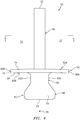
FIG. 4 is a schematic illustration of a rotor blade. -
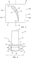
FIG. 5 is a cross-sectional illustration of the rotor blade taken along line 5-5 inFIG. 4 . -
FIG. 6 is a side schematic illustration of the rotor blade. -
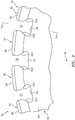
FIG. 7 is a partial illustration of interfaces between a plurality of the rotor blades and the rotor disk, where platforms of two of the rotor blades are partially shown. -
FIG. 8 is a partial side sectional illustration of the interface taken along line 8-8 inFIG. 7 . -
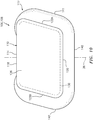
FIG. 9 is an illustration of an inner side of a platform seal mated with a seal element. -
FIG. 10 is an illustration of an outer side of the platform seal and the seal element. -
FIG. 11 is an illustration of the seal element in a relaxed and/or unassembled state. -
FIG. 12 is a cross-sectional illustration of the seal element taken along line 12-12 inFIG. 11 . -
FIGS. 13-14B are cross-sectional illustrations of alternate seal element geometries. -
FIG. 15 is a perspective illustration of the platform seal and the seal element configured between a rim lug and a rotor blade platform, where the rotor blade is shown without an airfoil for easy of illustration. -
FIG. 16 is a partial illustration of the rotor assembly configured with a plurality of the platform seals and a plurality of the seal elements. -
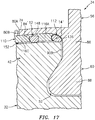
FIG. 17 is a partial cross-sectional illustration of the rotor assembly ofFIG. 16 . -
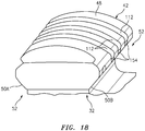
FIG. 18 is a perspective illustration of a rim lug configured with a plurality of the seal elements and without the platform seal. -
FIG. 19 is a partial illustration of an interface between the rotor blade platform and the rim lug ofFIG. 18 . -
FIG. 20 is a partial illustration of an interface between another rotor blade platform and another rim lug. -
FIG. 21 is a partial perspective illustration of the rim lug ofFIG. 20 configured with a plurality of the seal elements. -
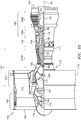
FIG. 22 is a side cutaway illustration of a gas turbine engine. -
FIG. 1 illustrates abladed rotor assembly 30 for a piece of rotational equipment. An example of such a piece of rotational equipment is a gas turbine engine for an aircraft propulsion system, an exemplary embodiment of which is described below in further detail with respect toFIG. 22 . However, therotor assembly 30 of the present disclosure is not limited to such an aircraft application nor a gas turbine engine application. Therotor assembly 30, for example, may alternatively be configured with rotational equipment such as an industrial gas turbine engine, a wind turbine, a water turbine or any other apparatus which includes a bladed rotor. - The
rotor assembly 30 ofFIG. 1 includes arotor disk 32 and a plurality ofrotor blades 34; e.g., compressor blades. Therotor disk 32 ofFIG. 1 is configured to rotate about arotational axis 36, which may also be an axial centerline of therotor assembly 30 and/or the piece of rotational equipment. - Referring to
FIG. 2 , therotor disk 32 includes arim 38 at a radial outer periphery of therotor disk 32. Thisrim 38 includes arim base 40 and a plurality of rim lugs 42. - The
rim base 40 extends circumferentially about (e.g., completely around) therotational axis 36. Referring toFIG. 3 , therim base 40 extends axially along therotational axis 36 between a first (e.g., forward and/or upstream) end 44 of therim 38 and a second (e.g., aft and/or downstream) end 46 of therim 38. - The rim lugs 42 of
FIG. 2 are arranged circumferentially about therim base 40 and therotational axis 36 in an annular array. Each of the rim lugs 42 projects radially out, in an outward direction relative to therotational axis 36, from an outer periphery of the rim base 40 a respective distallug end surface 48. Each of the rim lugs 42 extends laterally (e.g., in a circumferential or tangential direction relative to the rotational axis 36) between opposing lug first and second side surfaces 50A and 50B (generally referred to as "50"). Referring toFIG. 3 , each of the rim lugs 42 extends (e.g., substantially) axially along therotational axis 36 between the rimfirst end 44 and the rimsecond end 46. - Referring to
FIG. 2 , the rim lugs 42 are circumferentially spaced about (e.g., completely around) therotational axis 36 so as to form an annular array ofmount slots 52. Each of themount slots 52 is disposed laterally between and formed by a circumferentially adjacent / neighboring pair of the rim lugs 42 and their side surfaces 50. Eachmount slot 52 extends radially inward into therotor disk 32 from respective distal lug end surfaces 48 to a respectiveslot end surface 54; e.g., a slot bottom surface. Eachmount slot 52 extends laterally between a respective one of the lugfirst side surfaces 50A and a respective one of the lug second side surfaces 50B. Eachmount slot 52 may extend (e.g., substantially) axially through (or axially into) therotor disk 32 as shown, for example, inFIG. 3 . - Referring to
FIG. 4 , eachrotor blade 34 includes arotor blade airfoil 56, arotor blade platform 58 and arotor blade mount 60. Therotor blade airfoil 56 projects radially out from therotor blade platform 58 in a spanwise direction to a (e.g., unshrouded)airfoil tip 62. Referring toFIG. 5 , therotor blade airfoil 56 includes an airfoil first (e.g., pressure and/or concave) side surface 64 and an airfoil second (e.g., suction and/or convex)side surface 66. These first and second side surfaces 64 and 66 extend along a chord line of theairfoil 56 between and meet at an airfoil (e.g., forward and/or upstream) leadingedge 68 and an airfoil (e.g., aft and/or downstream) trailingedge 70. - The
rotor blade platform 58 ofFIG. 4 is radially between and connected to therotor blade airfoil 56 and therotor blade mount 60. Therotor blade platform 58 is configured to form a portion of an inner peripheral boarder of a gas path 72 (e.g., a core gas path) extending axially across therotor assembly 30; e.g., a gas path into which therotor blade airfoils 56 radially extend. Therotor blade platform 58 ofFIG. 5 , for example, includes anouter platform surface 74 that extends axially along therotational axis 36 between a platform first (e.g., forward and/or upstream)edge 76 and a platform second (e.g., aft and/or downstream)edge 78. Theouter platform surface 74 extends circumferentially between opposing platform first and second side edges 80A and 80B (generally referred to as "80"). - Referring to
FIG. 4 , therotor blade platform 58 is configured with a platformfirst side segment 82A (e.g., a side projection and/or wing) and a platformsecond side segment 82B (e.g., a side projection and/or wing), whichsegments first side segment 82A projects circumferentially away from theairfoil 56 and themount 60 to thefirst side edge 80A. This platformfirst side segment 82A is thereby cantilevered from themount 60. The platformfirst side segment 82A extends radially between theouter platform surface 74 and a first segment of aninner platform surface 84. The platformsecond side segment 82B projects circumferentially away from theairfoil 56 and themount 60 to thesecond side edge 80B. This platformsecond side segment 82B is thereby cantilevered from themount 60. The platformsecond side segment 82B extends radially between theouter platform surface 74 and a second segment ofinner platform surface 84. - The rotor blade mount 60 of
FIG. 4 includes amount neck 86 and amount root 88. Themount neck 86 extends radially between and is connected to therotor blade platform 58 and themount root 88. Themount neck 86 extends laterally between opposing neck first and second side surfaces 90A and 90B (generally referred to as "90"). Referring toFIG. 6 , themount neck 86 extends (e.g., substantially) axially along therotational axis 36 between a first (e.g., forward and/or upstream) end 92 of themount 60 and a second (e.g., aft and/or downstream) end 94 of themount 60. - The
mount root 88 extends (e.g., substantially) axially along therotational axis 36 between the mountfirst end 92 and the mountsecond end 94. Themount root 88 ofFIG. 4 flares laterally out from themount neck 86 so as to form, for example, a dovetail attachment. The present disclosure, however, is not limited to such an exemplary attachment configuration. Themount root 88 projects radially inward from themount neck 86 to a mountdistal end surface 96; e.g., a mount bottom surface. - Referring to
FIG. 7 , therotor blades 34 are arranged circumferentially around therotor disk 32 and therotational axis 36 in an annular array. Each of therotor blades 34 is attached to therotor disk 32 via a mechanical joint; e.g., a dovetail interface. The rotor blade mount 60 of eachrotor blade 34, for example, is mated with (e.g., slide into and seated within) a respective one of themount slots 52 in therotor disk 32. Referring toFIG. 8 , the rotor blade mounts 60 may be axially secured within themount slots 52 using one ormore retainers 98 and 100 (e.g., retaining rings) respectively seated inretainer slots rim base 40. The present disclosure, however, is not limited to the foregoing exemplary retainer configuration. - Referring to
FIG. 7 , during rotational equipment operation and/or rotation of therotor assembly 30 about itsrotational axis 36, fluid (e.g., compressed air) may leak across therotor assembly 30. For example, the fluid may leak axially through radial gaps between the rim lugs 42 and therotor blade platforms 58. Fluid may also or alternatively leak axially through lateral gaps between the rim lugs 42 and the rotor blade mounts 60. Fluid may still also or alternatively leak radially through lateral gaps between the platform edges 80. Such leakage may reduce performance of the rotational equipment. Therefore, to reduce and/or prevent such fluid leakage across therotor assembly 30, therotor assembly 30 of the present disclosure further includes a seal assembly 106, examples of which are shown inFIGS. 9-21 . - The seal assembly 106 of
FIGS. 9 and10 includes a plurality of seal component pairs 108, an exemplary one of which is shown. Eachseal component pair 108 includes aplatform seal 110 and aseal element 112. - The
platform seal 110 includes a platform seal base 114 (e.g., a base plate) and one or moreseal element locators FIG. 10 , theplatform seal base 114 extends (e.g., substantially) axially along therotational axis 36 between a seal base first (e.g., forward and/or upstream)end 118 and a seal base second (e.g., aft and/or downstream)end 120. Theplatform seal base 114 extends laterally (e.g., circumferentially) between opposing seal base first andsecond sides platform seal base 114 extends vertically (e.g., radially) between a platform seal inner surface 124 (seeFIG. 9 ) and a platform seal outer surface 126 (seeFIG. 10 ). - Referring to
FIG. 9 , the element locators 116 are connected to theplatform seal base 114. Each of the element locators 116 projects vertically out from theplatform seal base 114 and its platform sealinner surface 124 to a respective distal locator end 128A, 128B, 128C (generally referred to as "128"). The element locators 116 are arranged laterally along the platform sealinner surface 124. Thefirst element locator 116A is disposed at (e.g., on, adjacent or proximate) the seal basefirst side 122A. Thesecond element locator 116B is disposed at the seal basesecond side 122B. Thethird element locator 116C is disposed laterally between the first and thesecond element locators inner surface 124. - With the foregoing configuration, the
platform seal 110 ofFIG. 9 is configured with a plurality ofgrooves rim shelf 130. Thefirst groove 129A is formed laterally between thefirst element locator 116A and thethird element locator 116C. Thesecond groove 129B is formed laterally between thesecond element locator 116B and thethird element locator 116C. Therim shelf 130 extends (e.g., completely, or partially) around an outer perimeter of theplatform seal 110; e.g., see dashed line inFIGS. 9 and10 . However, in other embodiments, therim shelf 130 may only extend along a portion of the outer perimeter of theplatform seal 110; e.g., partially or completely along one or each of theends platform seal 110 may be configured without therim shelf 130. - Each
platform seal 110 may be configured as a monolithic body. The term "monolithic" may describe a single unitary body formed without severable components. For example, eachplatform seal 110 may be laid up, cast, machined and/or otherwise formed from a single body of material. In another example, eachplatform seal 110 may be formed from a plurality of discretely formed segments which are subsequently permanently bonded together; e.g., welded, adhered, etc. By contrast, the term "non-monolithic" may described a body formed from a plurality of discretely formed bodies that are severable; e.g., may be disassembly from one another. The present disclosure, however, is not limited to monolithic platform seals. - The
platform seal 110 is formed from platform seal material. Examples of the platform seal material may include, but are not limited to, metal, polymeric material and ceramic material. Examples of the metal include, but are not limited to, aluminum (Al), nickel (Ni), titanium (Ti), and alloys of any one or more of the foregoing. Examples of the polymetric material may include, but are not limited to, fiber-reinforced thermoplastic material and fiber-reinforced thermoset material. An example of the ceramic material is, but is not limited to, ceramic matrix composite (CMC) material. - The
seal element 112 ofFIG. 11 (shown in a relaxed and/or non-assembled state) is configured as an elongated seal element. Thisseal element 112, for example, has a relatively small cross-sectional width 132 (e.g., diameter) and a relatively longlongitudinal length 134. Thislongitudinal length 134 may be measured along alongitudinal centerline 136 of theseal element 112 between opposing ends 138A and 138B (generally referred to as "138") of theseal element 112. Thelongitudinal length 134 may be at least four times (4x), ten times (10x), fifteen times (15x), twenty times (20x), or more thecross-sectional width 137; e.g., thelength 134 may be between 10x and 30x thewidth 137. The present disclosure, however, is not limited to the foregoing exemplary length-to-width ratios. Thelongitudinal length 134 may be sized such that theseal element 112 covers one or more or each of the gaps between theelements FIGS. 16 and17 . Thelongitudinal length 134 may also be sized such that theseal element 112 engages the locators 116 in order to retainseal element 112 in place during operation. - In a relaxed / unassembled state as shown in
FIG. 12 , theseal element 112 may have a circular cross-sectional geometry when viewed, for example, in a plane perpendicular to thelongitudinal centerline 136. The present disclosure, however, is not limited to such an exemplary seal element cross-sectional geometry. For example, in other embodiments, theseal element 112 may be configured with a non-circular cross-sectional geometry. Examples of non-circular cross-sectional geometries include, but are not limited to, an oval or elliptical cross-sectional geometry (e.g., seeFIG. 13 ), a rectangular cross-sectional geometry (e.g., seeFIGS. 14A and 14B ), or any other desired cross-sectional geometry. - The
seal element 112 may be configured as a compliant seal element. Theseal element 112, for example, may be configured as a rope seal element (e.g., a braided wire rope seal element), a (e.g., single strand) wire seal element or a sheet material (e.g., metal) seal element. - The
seal element 112 is formed from seal element material, which may be the same as or different than the platform seal material. Examples of the seal element material may include, but are not limited to, metal and polymeric material. Examples of the metal include, but are not limited to, aluminum (Al), nickel (Ni), titanium (Ti), and alloys of any one or more of the foregoing. Examples of the polymetric material may include, but are not limited to, fiber-reinforced thermoplastic material and fiber-reinforced thermoset material. - Referring to
FIGS. 9 and10 , theseal element 112 is configured with theplatform seal 110. Theseal element 112 ofFIG. 9 , for example, is wrapped substantially around the perimeter of theplatform seal 110 and interwoven between the element locators 116. - One or more intermediate segments 140-142 (e.g., longitudinal lengths along the centerline 136) of the
seal element 112 are seated on therim shelf 130 and abutted against the element locators 116. The firstintermediate segment 140 extends laterally along the seal base second end 120 (or alternatively the seal base first end 118). The secondintermediate segment 141 extends (e.g., substantially) axially along the seal basefirst side 122A between the seal base first and second ends 118 and 120. This secondintermediate segment 141 is angularly offset from the firstintermediate segment 140 by a first offsetangle 144; e.g., an obtuse angle or alternatively a right angle or an acute angle. The thirdintermediate segment 142 extends (e.g., substantially) axially along the seal basesecond side 122B between the seal base first and second ends 118 and 120. This thirdintermediate segment 142 is angularly offset from the firstintermediate segment 140 by a second offsetangle 146; e.g., an acute angle or alternatively a right angle or an obtuse angle. Note, the seal locators 116 are shaped such that the locators 116 are operable to retain the position of theseal element 112 in a position where theseal element 112 is operable to fill / cover one or more or each of the gaps between theelements FIGS. 16 and17 . - A first end segment 148 (e.g., longitudinal length along the centerline 136) of the
seal element 112 is bent around thefirst element locator 116A and projects into thefirst groove 129A from the seal base first end 118 (or alternatively the seal base second end 120). Thefirst end segment 148 is bent back and axially overlaps the secondintermediate segment 141. A second end segment 150 (e.g., longitudinal length along the centerline 136) of theseal element 112 is bent around thesecond element locator 116B and projects into thesecond groove 129B from the seal base first end 118 (or alternatively the seal base second end 120). Thesecond end segment 150 is bent back and axially overlaps the thirdintermediate segment 142. Theend segments seal element 112 to theplatform seal 110. With this arrangement, thecenterline 136 of theseal element 112 follows a tortuous trajectory. - Referring to
FIG. 15 , eachseal component pair 108 is arranged with a respective one of the rim lugs 42 such that eachseal component pair 108 is uniquely associated with a single one of the rim lugs 42. Eachseal component pair 108 is received, inset and seated within arespective lug groove 152 in therespective rim lug 42. In a rest state, theplatform seal 110 as well as theseal element 112 may radially rest against therespective lug 42. However, during rotational equipment operation, theplatform seal 110 and/or theseal element 112 may be forced radially outward (e.g., via centrifugal force) against therotor blade platforms 58 ofadjacent rotor blades 34 as shown, for example, inFIG. 16 . - In the state of
FIG. 16 , the firstintermediate segment 140 of theseal element 112 may sealingly engage (e.g., be pressed radially against, abut and contact) the first and/or second segments of the inner platform surfaces 84 ofadjacent rotor blades 34. The firstintermediate segment 140 may thereby substantially seal the radial gap between therespective rim lug 42 and the adjacentrotor blade platforms 58. - Each
intermediate segment inner platform surface 84 and a respective neck side surface 90. Eachintermediate segment intermediate segment respective rim lug 42 and the respective neck side surface 90; see alsoFIG. 17 . Here, a portion of thecenterline 136 within eachintermediate segment mount 60. - Referring to
FIG. 17 , eachplatform seal 110 may also sealingly engage (e.g., be pressed radially against, abut and contact) the first and/or second segments of the inner platform surfaces 84 ofadjacent rotor blades 34. Theplatform seal 110 may thereby substantially seal the lateral gap between the edges 80 of the adjacentrotor blade platforms 58. Theplatform seal 110 may also further seal the radial gap between therespective rim lug 42 and the adjacentrotor blade platforms 58. - The seal assembly 106 of
FIG. 18 includes a plurality of sets of theseal elements 112. Each set of theseal elements 112 includes one ormore seal elements 112, which may have a similar configuration as described above. Each of theseal elements 112 in a set is disposed in arespective groove 154 in a respective one of the rim lugs 42. With this arrangement, each of theseal elements 112 may extend laterally across therespective rim lug 42; e.g., between the opposing sides 50. It is worth nothing, theseal elements 112 are not limited to single or multiple wire seal configuration. As discussed above, eachseal element 112 can be constructed out of polymetric material including, but are not limited to, fiber-reinforced thermoplastic material and fiber-reinforced thermoset material. Alternatively, eachseal element 112 can be constructed out of shaped metal sheet to achieve the desired flow restriction between thelug surface 48 and therotor blade platforms 58. - During rotational equipment operation, the
seal elements 112 may be forced radially outward (e.g., via centrifugal force) against therotor blade platforms 58 ofadjacent rotor blades 34 as shown, for example, inFIG. 19 . In this state, eachseal element 112 may sealingly engage (e.g., be pressed radially against, abut and contact) the first and/or second segments of the inner platform surfaces 84 of adjacent rotor blades 34 (one shown inFIG. 19 ). Theseal elements 112 may thereby substantially seal the radial gap between therespective rim lug 42 and the adjacentrotor blade platforms 58. In addition, ends 138 of theseal elements 112 may respectively sealingly engage (e.g., be pressed laterally against, abut and contact) the respective neck side surface 90. Eachseal element end 138 may thereby at least partially seal the lateral gap between therespective rim lug 42 and the respective neck side surface 90. - It is also worth noting, in the embodiment of
FIG. 19 , theinner surface 84 of each platform segment 82 extends radially inward as thatinner surface 84 extends from the respective edge 80 to themount 60. Similarly, thelug surface 48 follows (e.g., has the same curvature as) theinner surfaces 84 of the adjacentrotor blade platforms 58. With this arrangement, a size (e.g., a radial height) of the lateral gap between thelugs 42 and the rotor blade mounts 60 may be reduced as compared to, for example, the arrangement shown inFIG. 16 . Thus, the present disclosure contemplates providing such a slopedinner platform surface 84 andlug surface 48 for each embodiment disclosed herein. - In some embodiments, referring to
FIG. 20 , one or more or each of theseal elements 112 may each be configured with one or morebent end segments 156. Eachbent end segment 156 is configured to extend radially along themount 60 and the surface 90 so as to further seal the lateral gap. - In some embodiments, referring to
FIG. 21 , one or more or each of the rim lugs 42 may include apocket 158. Thispocket 158 may be arranged axially between an adjacent pair of theseal elements 112. Thepocket 158 may serve to reduce the rotating mass of therotor disk 32 and/or provide a fluid path within therotor assembly 30. -
FIG. 22 is a side cutaway illustration of a gearedturbine engine 160 with which therotor assembly 30 ofFIG. 1 may be included. Thisturbine engine 160 extends along therotational axis 36 between anupstream airflow inlet 162 and adownstream airflow exhaust 164. Theturbine engine 160 includes afan section 166, acompressor section 167, acombustor section 168 and aturbine section 169. Thecompressor section 167 includes a low pressure compressor (LPC)section 167A and a high pressure compressor (HPC)section 167B. Theturbine section 169 includes a high pressure turbine (HPT)section 169A and a low pressure turbine (LPT)section 169B. - The engine sections 166-169B are arranged sequentially along the
rotational axis 36 within anengine housing 170. Thishousing 170 includes an inner case 172 (e.g., a core case) and an outer case 174 (e.g., a fan case). Theinner case 172 may house one or more of theengine sections 167A-169B; e.g., an engine core. Theouter case 174 may house at least thefan section 166. - Each of the
engine sections rotor assembly 30 ofFIG. 1 . Therotor assembly 30, for example, may be included in one of thecompressor rotors FIG. 22 includes a plurality of rotor blades arranged circumferentially around and connected to one or more respective rotor disks. The rotor blades, for example, may be formed integral with or mechanically fastened, welded, brazed, adhered and/or otherwise attached to the respective rotor disk(s). - The
fan rotor 176 is connected to agear train 182, for example, through afan shaft 184. Thegear train 182 and theLPC rotor 177 are connected to and driven by theLPT rotor 180 through alow speed shaft 185. TheHPC rotor 178 is connected to and driven by theHPT rotor 179 through ahigh speed shaft 186. The shafts 184-186 are rotatably supported by a plurality ofbearings 188; e.g., rolling element and/or thrust bearings. Each of thesebearings 188 is connected to theengine housing 170 by at least one stationary structure such as, for example, an annular support strut. - During operation, air enters the
turbine engine 160 through theairflow inlet 162. This air is directed through thefan section 166 and into a core gas path 190 (e.g., thegas path 72; seeFIG. 4 ) and abypass gas path 192. Thecore gas path 190 extends sequentially through theengine sections 167A-169B. The air within thecore gas path 190 may be referred to as "core air". Thebypass gas path 192 extends through a bypass duct, which bypasses the engine core. The air within thebypass gas path 192 may be referred to as "bypass air". - The core air is compressed by the
compressor rotors combustion chamber 194 of a combustor in thecombustor section 168. Fuel is injected into thecombustion chamber 194 and mixed with the compressed core air to provide a fuel-air mixture. This fuel air mixture is ignited and combustion products thereof flow through and sequentially cause theturbine rotors turbine rotors compressor rotors turbine rotor 180 also drives rotation of thefan rotor 176, which propels bypass air through and out of thebypass gas path 192. The propulsion of the bypass air may account for a majority of thrust generated by theturbine engine 160, e.g., more than seventy-five percent (75%) of engine thrust. Theturbine engine 160 of the present disclosure, however, is not limited to the foregoing exemplary thrust ratio. - The
rotor assembly 30 may be included in various turbine engines other than the one described above as well as in other types of rotational equipment. Therotor assembly 30, for example, may be included in a geared turbine engine where a gear train connects one or more shafts to one or more rotors in a fan section, a compressor section and/or any other engine section. Alternatively, therotor assembly 30 may be included in a turbine engine configured without a gear train. Therotor assembly 30 may be included in a geared or non-geared turbine engine configured with a single spool, with two spools (e.g., seeFIG. 22 ), or with more than two spools. The turbine engine may be configured as a turbofan engine, a turbojet engine, a propfan engine, a pusher fan engine or any other type of turbine engine. The present disclosure therefore is not limited to any particular types or configurations of turbine engines or rotational equipment. - While various embodiments of the present disclosure have been described, it will be apparent to those of ordinary skill in the art that many more embodiments and implementations are possible within the scope of the disclosure. For example, the present disclosure as described herein includes several aspects and embodiments that include particular features. Although these features may be described individually, it is within the scope of the present disclosure that some or all of these features may be combined with any one of the aspects and remain within the scope of the disclosure. Accordingly, the present disclosure is not to be restricted except in light of the attached claims and their equivalents.
Claims (15)
- A rotor assembly (30) for a piece of rotational equipment, comprising:a rotor disk (32) configured to rotate about a rotational axis (36);a rotor blade (34) including an airfoil (56), a platform (58) and a mount (60) attaching the rotor blade (34) to the rotor disk (32); anda seal element (112) seated in a groove of the rotor disk (32), the seal element (112) configured to sealingly engage the platform (58) and the mount (60).
- The rotor assembly (30) of claim 1, wherein:the mount (60) includes a root (88) and a neck (86); andthe seal element (112) is configured to sealingly engage the neck (86).
- The rotor assembly (30) of claim 1 or 2, wherein the seal element (112) is configured to radially abut against the platform (58); and
laterally abut against the mount (60). - The rotor assembly (30) of claim 1, 2, or 3, wherein:the rotor disk (32) includes a lug (42) and a slot (52) partially formed by the lug (42);the mount (60) is seated within the slot (52); andthe seal element (112) extends laterally across the lug (42).
- The rotor assembly (30) of any preceding claim, wherein:the seal element (112) follows a longitudinal centerline (136); anda portion of the longitudinal centerline (136) extends along and is parallel with the mount (60).
- The rotor assembly (30) of any preceding claim, wherein the seal element (112) comprises an elongated seal element (112) that follows a longitudinal centerline (136) with a tortuous trajectory.
- The rotor assembly (30) of any preceding claim, wherein:the seal element (112) comprises an elongated seal element;a first length of the elongated seal element follows a first trajectory; anda second length of the elongated seal element follows a second trajectory that is angularly offset from the first trajectory.
- The rotor assembly (30) of any preceding claim, further comprising a platform seal (110) configured to sealingly engage the platform (58) and retain the seal element (112) within the groove, wherein the seal element (112) is optionally wrapped around the platform seal (110).
- The rotor assembly (30) of any preceding claim, wherein the seal element (112) comprises:a rope seal element; and/ora wire seal element; and/orpolymeric material; and/orsheet metal.
- The rotor assembly (30) of any preceding claim, wherein:an inner surface (84) of the platform (58) extends radially inwards as the inner surface (84) extends from a lateral distal edge of the platform (58) to the mount (60); anda lug surface (48) of the rotor disk (32) follows the inner surface (84).
- The rotor assembly (30) of any preceding claim, wherein the rotor blade (34) comprises a compressor blade.
- A rotor assembly (30) for a turbine engine (160), comprising:a rotor disk (32) configured to rotate about a rotational axis (36), the rotor disk (32) including a first lug (42), a second lug (42) and a slot (52) laterally between and formed by the first lug (42) and the second lug (42);a rotor blade (34) including an airfoil (56), a platform (58) and a mount (60) seated within the slot (52); anda seal element (112) configured toat least partially seal a gap between the first lug (42) and the platform (58); andat least partially seal a gap between the first lug (42) and the mount (60).
- The rotor assembly (30) of claim 12, wherein the seal element (112) is configured as an elongated compliant seal element.
- The rotor assembly (30) of claim 12 or 13, wherein at least a portion of the seal element (112) extends laterally along an inner surface (84) of the platform (58),
wherein a second portion of the seal element (112) optionally extends axially along the mount (60). - A rotor assembly (30) for a turbine engine (160), comprising:a rotor disk (32) configured to rotate about a rotational axis (36), the rotor disk (32) including a first lug (42), a second lug (42) and a slot (52) laterally between and formed by the first lug (42) and the second lug (42);a rotor blade (34) including an airfoil (56), a platform (58) and a mount (60) seated within the slot (52); anda seal element (112) extending laterally along the first lug (42) and located radially between the rotor disk (32) and the platform (58), the seal element (112) configured as a rope seal element, a wire seal element or a polymer seal element.
Applications Claiming Priority (1)
| Application Number | Priority Date | Filing Date | Title |
|---|---|---|---|
| US16/747,089 US11512602B2 (en) | 2020-01-20 | 2020-01-20 | Seal element for sealing a joint between a rotor blade and a rotor disk |
Publications (2)
| Publication Number | Publication Date |
|---|---|
| EP3851634A1 true EP3851634A1 (en) | 2021-07-21 |
| EP3851634B1 EP3851634B1 (en) | 2022-12-28 |
Family
ID=73543088
Family Applications (1)
| Application Number | Title | Priority Date | Filing Date |
|---|---|---|---|
| EP20208865.4A Active EP3851634B1 (en) | 2020-01-20 | 2020-11-20 | Seal element for sealing a joint between a rotor blade and a rotor disk of a turbine engine |
Country Status (2)
| Country | Link |
|---|---|
| US (1) | US11512602B2 (en) |
| EP (1) | EP3851634B1 (en) |
Families Citing this family (1)
| Publication number | Priority date | Publication date | Assignee | Title |
|---|---|---|---|---|
| US12228142B1 (en) | 2023-08-04 | 2025-02-18 | Rtx Corporation | Control of leakage for gas turbine engine compressor blades |
Citations (5)
| Publication number | Priority date | Publication date | Assignee | Title |
|---|---|---|---|---|
| DE2658345A1 (en) * | 1976-12-23 | 1978-06-29 | Motoren Turbinen Union | Gas turbine impeller for turbine or compressor part - has sealing pieces between blade roots to prevent leakage recirculation |
| US5478207A (en) * | 1994-09-19 | 1995-12-26 | General Electric Company | Stable blade vibration damper for gas turbine engine |
| US6315298B1 (en) * | 1999-11-22 | 2001-11-13 | United Technologies Corporation | Turbine disk and blade assembly seal |
| US6682307B1 (en) * | 1999-05-14 | 2004-01-27 | Siemens Aktiengesellschaft | Sealing system for a rotor of a turbo engine |
| EP1865153A2 (en) * | 2006-06-05 | 2007-12-12 | United Technologies Corporation | Rotor disk and blade arrangement and method of assembly thereof |
Family Cites Families (11)
| Publication number | Priority date | Publication date | Assignee | Title |
|---|---|---|---|---|
| GB1460714A (en) | 1973-06-26 | 1977-01-06 | Rolls Royce | Bladed rotor for a gas turbine engine |
| US4500098A (en) * | 1983-12-22 | 1985-02-19 | United Technologies Corporation | Gas seal for rotating components |
| US5257909A (en) | 1992-08-17 | 1993-11-02 | General Electric Company | Dovetail sealing device for axial dovetail rotor blades |
| EP1180196B1 (en) | 1999-05-14 | 2005-02-16 | Siemens Aktiengesellschaft | Turbo-machine comprising a sealing system for a rotor |
| US6375429B1 (en) | 2001-02-05 | 2002-04-23 | General Electric Company | Turbomachine blade-to-rotor sealing arrangement |
| US6832892B2 (en) * | 2002-12-11 | 2004-12-21 | General Electric Company | Sealing of steam turbine bucket hook leakages using a braided rope seal |
| US8215914B2 (en) | 2008-07-08 | 2012-07-10 | General Electric Company | Compliant seal for rotor slot |
| GB201200845D0 (en) * | 2012-01-19 | 2012-02-29 | Rolls Royce Plc | Method of sealing cooling holes |
| US9175573B2 (en) | 2012-11-28 | 2015-11-03 | General Electric Company | Dovetail attachment seal for a turbomachine |
| US9470098B2 (en) | 2013-03-15 | 2016-10-18 | General Electric Company | Axial compressor and method for controlling stage-to-stage leakage therein |
| US10393135B2 (en) | 2017-02-09 | 2019-08-27 | DOOSAN Heavy Industries Construction Co., LTD | Compressor blade locking mechanism in disk with axial groove |
-
2020
- 2020-01-20 US US16/747,089 patent/US11512602B2/en active Active
- 2020-11-20 EP EP20208865.4A patent/EP3851634B1/en active Active
Patent Citations (5)
| Publication number | Priority date | Publication date | Assignee | Title |
|---|---|---|---|---|
| DE2658345A1 (en) * | 1976-12-23 | 1978-06-29 | Motoren Turbinen Union | Gas turbine impeller for turbine or compressor part - has sealing pieces between blade roots to prevent leakage recirculation |
| US5478207A (en) * | 1994-09-19 | 1995-12-26 | General Electric Company | Stable blade vibration damper for gas turbine engine |
| US6682307B1 (en) * | 1999-05-14 | 2004-01-27 | Siemens Aktiengesellschaft | Sealing system for a rotor of a turbo engine |
| US6315298B1 (en) * | 1999-11-22 | 2001-11-13 | United Technologies Corporation | Turbine disk and blade assembly seal |
| EP1865153A2 (en) * | 2006-06-05 | 2007-12-12 | United Technologies Corporation | Rotor disk and blade arrangement and method of assembly thereof |
Also Published As
| Publication number | Publication date |
|---|---|
| US20210222571A1 (en) | 2021-07-22 |
| EP3851634B1 (en) | 2022-12-28 |
| US11512602B2 (en) | 2022-11-29 |
Similar Documents
| Publication | Publication Date | Title |
|---|---|---|
| EP3404214B1 (en) | Blade outer air seal assembly and gas turbine engine with such an assembly | |
| US20180340615A1 (en) | Shaped spring element for a non-contact seal device | |
| EP3112601A1 (en) | Segmented non-contact seal assembly for rotational equipment | |
| EP3447344B1 (en) | Hydrostatic non-contact seal with dual material | |
| EP3431836B1 (en) | Non-contact seal with non-straight spring beam(s) | |
| EP3418610B1 (en) | Hydrostatic non-contact seal with weight reduction pocket | |
| EP2978938B1 (en) | Turbine engine assembly with l-shaped feather seal | |
| EP3415798A1 (en) | Hydrostatic non-contact seal with varied thickness beams | |
| EP3309362B1 (en) | Stator vane rail | |
| US20180017168A1 (en) | Multi-ply seal ring | |
| EP2984292B1 (en) | Stator vane platform with flanges | |
| EP3428490A1 (en) | Hydrostatic non-contact seal with offset outer ring | |
| EP3428489A1 (en) | Hydrostatic non-contact seal with seal carrier elimination | |
| EP3181945B1 (en) | Damper seal installation features | |
| EP3851634B1 (en) | Seal element for sealing a joint between a rotor blade and a rotor disk of a turbine engine | |
| EP3832177B1 (en) | Brush seal with crossing bristles | |
| EP3851639A2 (en) | Rotor blade and rotor assemblies for a gas turbine engine | |
| US11208892B2 (en) | Rotor assembly with multiple rotor disks | |
| EP3708778B1 (en) | Inserts for slotted integrally bladed rotor | |
| EP4286654B1 (en) | Joint between gas turbine engine components with bonded fastener(s) | |
| EP3896260B1 (en) | Seal element for sealing a joint between a rotor blade and a rotor disk |
Legal Events
| Date | Code | Title | Description |
|---|---|---|---|
| PUAI | Public reference made under article 153(3) epc to a published international application that has entered the european phase |
Free format text: ORIGINAL CODE: 0009012 |
|
| STAA | Information on the status of an ep patent application or granted ep patent |
Free format text: STATUS: THE APPLICATION HAS BEEN PUBLISHED |
|
| AK | Designated contracting states |
Kind code of ref document: A1 Designated state(s): AL AT BE BG CH CY CZ DE DK EE ES FI FR GB GR HR HU IE IS IT LI LT LU LV MC MK MT NL NO PL PT RO RS SE SI SK SM TR |
|
| STAA | Information on the status of an ep patent application or granted ep patent |
Free format text: STATUS: REQUEST FOR EXAMINATION WAS MADE |
|
| 17P | Request for examination filed |
Effective date: 20220121 |
|
| RBV | Designated contracting states (corrected) |
Designated state(s): AL AT BE BG CH CY CZ DE DK EE ES FI FR GB GR HR HU IE IS IT LI LT LU LV MC MK MT NL NO PL PT RO RS SE SI SK SM TR |
|
| GRAP | Despatch of communication of intention to grant a patent |
Free format text: ORIGINAL CODE: EPIDOSNIGR1 |
|
| STAA | Information on the status of an ep patent application or granted ep patent |
Free format text: STATUS: GRANT OF PATENT IS INTENDED |
|
| INTG | Intention to grant announced |
Effective date: 20220706 |
|
| GRAS | Grant fee paid |
Free format text: ORIGINAL CODE: EPIDOSNIGR3 |
|
| GRAA | (expected) grant |
Free format text: ORIGINAL CODE: 0009210 |
|
| STAA | Information on the status of an ep patent application or granted ep patent |
Free format text: STATUS: THE PATENT HAS BEEN GRANTED |
|
| AK | Designated contracting states |
Kind code of ref document: B1 Designated state(s): AL AT BE BG CH CY CZ DE DK EE ES FI FR GB GR HR HU IE IS IT LI LT LU LV MC MK MT NL NO PL PT RO RS SE SI SK SM TR |
|
| REG | Reference to a national code |
Ref country code: GB Ref legal event code: FG4D |
|
| REG | Reference to a national code |
Ref country code: CH Ref legal event code: EP |
|
| REG | Reference to a national code |
Ref country code: DE Ref legal event code: R096 Ref document number: 602020007199 Country of ref document: DE |
|
| REG | Reference to a national code |
Ref country code: AT Ref legal event code: REF Ref document number: 1540617 Country of ref document: AT Kind code of ref document: T Effective date: 20230115 |
|
| REG | Reference to a national code |
Ref country code: IE Ref legal event code: FG4D |
|
| REG | Reference to a national code |
Ref country code: LT Ref legal event code: MG9D |
|
| PG25 | Lapsed in a contracting state [announced via postgrant information from national office to epo] |
Ref country code: SE Free format text: LAPSE BECAUSE OF FAILURE TO SUBMIT A TRANSLATION OF THE DESCRIPTION OR TO PAY THE FEE WITHIN THE PRESCRIBED TIME-LIMIT Effective date: 20221228 Ref country code: NO Free format text: LAPSE BECAUSE OF FAILURE TO SUBMIT A TRANSLATION OF THE DESCRIPTION OR TO PAY THE FEE WITHIN THE PRESCRIBED TIME-LIMIT Effective date: 20230328 Ref country code: LT Free format text: LAPSE BECAUSE OF FAILURE TO SUBMIT A TRANSLATION OF THE DESCRIPTION OR TO PAY THE FEE WITHIN THE PRESCRIBED TIME-LIMIT Effective date: 20221228 Ref country code: FI Free format text: LAPSE BECAUSE OF FAILURE TO SUBMIT A TRANSLATION OF THE DESCRIPTION OR TO PAY THE FEE WITHIN THE PRESCRIBED TIME-LIMIT Effective date: 20221228 |
|
| REG | Reference to a national code |
Ref country code: NL Ref legal event code: MP Effective date: 20221228 |
|
| REG | Reference to a national code |
Ref country code: AT Ref legal event code: MK05 Ref document number: 1540617 Country of ref document: AT Kind code of ref document: T Effective date: 20221228 |
|
| PG25 | Lapsed in a contracting state [announced via postgrant information from national office to epo] |
Ref country code: RS Free format text: LAPSE BECAUSE OF FAILURE TO SUBMIT A TRANSLATION OF THE DESCRIPTION OR TO PAY THE FEE WITHIN THE PRESCRIBED TIME-LIMIT Effective date: 20221228 Ref country code: LV Free format text: LAPSE BECAUSE OF FAILURE TO SUBMIT A TRANSLATION OF THE DESCRIPTION OR TO PAY THE FEE WITHIN THE PRESCRIBED TIME-LIMIT Effective date: 20221228 Ref country code: HR Free format text: LAPSE BECAUSE OF FAILURE TO SUBMIT A TRANSLATION OF THE DESCRIPTION OR TO PAY THE FEE WITHIN THE PRESCRIBED TIME-LIMIT Effective date: 20221228 Ref country code: GR Free format text: LAPSE BECAUSE OF FAILURE TO SUBMIT A TRANSLATION OF THE DESCRIPTION OR TO PAY THE FEE WITHIN THE PRESCRIBED TIME-LIMIT Effective date: 20230329 |
|
| P01 | Opt-out of the competence of the unified patent court (upc) registered |
Effective date: 20230521 |
|
| PG25 | Lapsed in a contracting state [announced via postgrant information from national office to epo] |
Ref country code: NL Free format text: LAPSE BECAUSE OF FAILURE TO SUBMIT A TRANSLATION OF THE DESCRIPTION OR TO PAY THE FEE WITHIN THE PRESCRIBED TIME-LIMIT Effective date: 20221228 |
|
| PG25 | Lapsed in a contracting state [announced via postgrant information from national office to epo] |
Ref country code: SM Free format text: LAPSE BECAUSE OF FAILURE TO SUBMIT A TRANSLATION OF THE DESCRIPTION OR TO PAY THE FEE WITHIN THE PRESCRIBED TIME-LIMIT Effective date: 20221228 Ref country code: RO Free format text: LAPSE BECAUSE OF FAILURE TO SUBMIT A TRANSLATION OF THE DESCRIPTION OR TO PAY THE FEE WITHIN THE PRESCRIBED TIME-LIMIT Effective date: 20221228 Ref country code: PT Free format text: LAPSE BECAUSE OF FAILURE TO SUBMIT A TRANSLATION OF THE DESCRIPTION OR TO PAY THE FEE WITHIN THE PRESCRIBED TIME-LIMIT Effective date: 20230428 Ref country code: ES Free format text: LAPSE BECAUSE OF FAILURE TO SUBMIT A TRANSLATION OF THE DESCRIPTION OR TO PAY THE FEE WITHIN THE PRESCRIBED TIME-LIMIT Effective date: 20221228 Ref country code: EE Free format text: LAPSE BECAUSE OF FAILURE TO SUBMIT A TRANSLATION OF THE DESCRIPTION OR TO PAY THE FEE WITHIN THE PRESCRIBED TIME-LIMIT Effective date: 20221228 Ref country code: CZ Free format text: LAPSE BECAUSE OF FAILURE TO SUBMIT A TRANSLATION OF THE DESCRIPTION OR TO PAY THE FEE WITHIN THE PRESCRIBED TIME-LIMIT Effective date: 20221228 Ref country code: AT Free format text: LAPSE BECAUSE OF FAILURE TO SUBMIT A TRANSLATION OF THE DESCRIPTION OR TO PAY THE FEE WITHIN THE PRESCRIBED TIME-LIMIT Effective date: 20221228 |
|
| PG25 | Lapsed in a contracting state [announced via postgrant information from national office to epo] |
Ref country code: SK Free format text: LAPSE BECAUSE OF FAILURE TO SUBMIT A TRANSLATION OF THE DESCRIPTION OR TO PAY THE FEE WITHIN THE PRESCRIBED TIME-LIMIT Effective date: 20221228 Ref country code: PL Free format text: LAPSE BECAUSE OF FAILURE TO SUBMIT A TRANSLATION OF THE DESCRIPTION OR TO PAY THE FEE WITHIN THE PRESCRIBED TIME-LIMIT Effective date: 20221228 Ref country code: IS Free format text: LAPSE BECAUSE OF FAILURE TO SUBMIT A TRANSLATION OF THE DESCRIPTION OR TO PAY THE FEE WITHIN THE PRESCRIBED TIME-LIMIT Effective date: 20230428 Ref country code: AL Free format text: LAPSE BECAUSE OF FAILURE TO SUBMIT A TRANSLATION OF THE DESCRIPTION OR TO PAY THE FEE WITHIN THE PRESCRIBED TIME-LIMIT Effective date: 20221228 |
|
| REG | Reference to a national code |
Ref country code: DE Ref legal event code: R097 Ref document number: 602020007199 Country of ref document: DE |
|
| PG25 | Lapsed in a contracting state [announced via postgrant information from national office to epo] |
Ref country code: DK Free format text: LAPSE BECAUSE OF FAILURE TO SUBMIT A TRANSLATION OF THE DESCRIPTION OR TO PAY THE FEE WITHIN THE PRESCRIBED TIME-LIMIT Effective date: 20221228 |
|
| RAP4 | Party data changed (patent owner data changed or rights of a patent transferred) |
Owner name: RTX CORPORATION |
|
| PLBE | No opposition filed within time limit |
Free format text: ORIGINAL CODE: 0009261 |
|
| STAA | Information on the status of an ep patent application or granted ep patent |
Free format text: STATUS: NO OPPOSITION FILED WITHIN TIME LIMIT |
|
| 26N | No opposition filed |
Effective date: 20230929 |
|
| PG25 | Lapsed in a contracting state [announced via postgrant information from national office to epo] |
Ref country code: SI Free format text: LAPSE BECAUSE OF FAILURE TO SUBMIT A TRANSLATION OF THE DESCRIPTION OR TO PAY THE FEE WITHIN THE PRESCRIBED TIME-LIMIT Effective date: 20221228 |
|
| PG25 | Lapsed in a contracting state [announced via postgrant information from national office to epo] |
Ref country code: IT Free format text: LAPSE BECAUSE OF FAILURE TO SUBMIT A TRANSLATION OF THE DESCRIPTION OR TO PAY THE FEE WITHIN THE PRESCRIBED TIME-LIMIT Effective date: 20221228 |
|
| REG | Reference to a national code |
Ref country code: CH Ref legal event code: PL |
|
| PG25 | Lapsed in a contracting state [announced via postgrant information from national office to epo] |
Ref country code: MC Free format text: LAPSE BECAUSE OF FAILURE TO SUBMIT A TRANSLATION OF THE DESCRIPTION OR TO PAY THE FEE WITHIN THE PRESCRIBED TIME-LIMIT Effective date: 20221228 |
|
| PG25 | Lapsed in a contracting state [announced via postgrant information from national office to epo] |
Ref country code: LU Free format text: LAPSE BECAUSE OF NON-PAYMENT OF DUE FEES Effective date: 20231120 |
|
| PG25 | Lapsed in a contracting state [announced via postgrant information from national office to epo] |
Ref country code: CH Free format text: LAPSE BECAUSE OF NON-PAYMENT OF DUE FEES Effective date: 20231130 |
|
| PG25 | Lapsed in a contracting state [announced via postgrant information from national office to epo] |
Ref country code: MC Free format text: LAPSE BECAUSE OF FAILURE TO SUBMIT A TRANSLATION OF THE DESCRIPTION OR TO PAY THE FEE WITHIN THE PRESCRIBED TIME-LIMIT Effective date: 20221228 Ref country code: LU Free format text: LAPSE BECAUSE OF NON-PAYMENT OF DUE FEES Effective date: 20231120 Ref country code: CH Free format text: LAPSE BECAUSE OF NON-PAYMENT OF DUE FEES Effective date: 20231130 |
|
| REG | Reference to a national code |
Ref country code: BE Ref legal event code: MM Effective date: 20231130 |
|
| REG | Reference to a national code |
Ref country code: IE Ref legal event code: MM4A |
|
| PG25 | Lapsed in a contracting state [announced via postgrant information from national office to epo] |
Ref country code: IE Free format text: LAPSE BECAUSE OF NON-PAYMENT OF DUE FEES Effective date: 20231120 |
|
| PG25 | Lapsed in a contracting state [announced via postgrant information from national office to epo] |
Ref country code: BE Free format text: LAPSE BECAUSE OF NON-PAYMENT OF DUE FEES Effective date: 20231130 |
|
| PG25 | Lapsed in a contracting state [announced via postgrant information from national office to epo] |
Ref country code: IE Free format text: LAPSE BECAUSE OF NON-PAYMENT OF DUE FEES Effective date: 20231120 Ref country code: BE Free format text: LAPSE BECAUSE OF NON-PAYMENT OF DUE FEES Effective date: 20231130 |
|
| PG25 | Lapsed in a contracting state [announced via postgrant information from national office to epo] |
Ref country code: BG Free format text: LAPSE BECAUSE OF FAILURE TO SUBMIT A TRANSLATION OF THE DESCRIPTION OR TO PAY THE FEE WITHIN THE PRESCRIBED TIME-LIMIT Effective date: 20221228 |
|
| PG25 | Lapsed in a contracting state [announced via postgrant information from national office to epo] |
Ref country code: BG Free format text: LAPSE BECAUSE OF FAILURE TO SUBMIT A TRANSLATION OF THE DESCRIPTION OR TO PAY THE FEE WITHIN THE PRESCRIBED TIME-LIMIT Effective date: 20221228 |
|
| PG25 | Lapsed in a contracting state [announced via postgrant information from national office to epo] |
Ref country code: CY Free format text: LAPSE BECAUSE OF FAILURE TO SUBMIT A TRANSLATION OF THE DESCRIPTION OR TO PAY THE FEE WITHIN THE PRESCRIBED TIME-LIMIT; INVALID AB INITIO Effective date: 20201120 |
|
| PG25 | Lapsed in a contracting state [announced via postgrant information from national office to epo] |
Ref country code: HU Free format text: LAPSE BECAUSE OF FAILURE TO SUBMIT A TRANSLATION OF THE DESCRIPTION OR TO PAY THE FEE WITHIN THE PRESCRIBED TIME-LIMIT; INVALID AB INITIO Effective date: 20201120 |
|
| REG | Reference to a national code |
Ref country code: DE Ref legal event code: R081 Ref document number: 602020007199 Country of ref document: DE Owner name: RTX CORPORATION (N.D.GES.D. STAATES DELAWARE),, US Free format text: FORMER OWNER: RAYTHEON TECHNOLOGIES CORP., FARMINGTON, CT, US |
|
| PG25 | Lapsed in a contracting state [announced via postgrant information from national office to epo] |
Ref country code: TR Free format text: LAPSE BECAUSE OF FAILURE TO SUBMIT A TRANSLATION OF THE DESCRIPTION OR TO PAY THE FEE WITHIN THE PRESCRIBED TIME-LIMIT Effective date: 20221228 |
|
| PGFP | Annual fee paid to national office [announced via postgrant information from national office to epo] |
Ref country code: DE Payment date: 20251022 Year of fee payment: 6 |
|
| PGFP | Annual fee paid to national office [announced via postgrant information from national office to epo] |
Ref country code: GB Payment date: 20251023 Year of fee payment: 6 |
|
| PGFP | Annual fee paid to national office [announced via postgrant information from national office to epo] |
Ref country code: FR Payment date: 20251023 Year of fee payment: 6 |