EP3851597B1 - Verbesserte urinalvorrichtung mit verbrauchbarer kappe - Google Patents
Verbesserte urinalvorrichtung mit verbrauchbarer kappe Download PDFInfo
- Publication number
- EP3851597B1 EP3851597B1 EP21150353.7A EP21150353A EP3851597B1 EP 3851597 B1 EP3851597 B1 EP 3851597B1 EP 21150353 A EP21150353 A EP 21150353A EP 3851597 B1 EP3851597 B1 EP 3851597B1
- Authority
- EP
- European Patent Office
- Prior art keywords
- urinal
- urinal apparatus
- consumable
- upper housing
- fins
- Prior art date
- Legal status (The legal status is an assumption and is not a legal conclusion. Google has not performed a legal analysis and makes no representation as to the accuracy of the status listed.)
- Active
Links
Images


Classifications
-
- A—HUMAN NECESSITIES
- A47—FURNITURE; DOMESTIC ARTICLES OR APPLIANCES; COFFEE MILLS; SPICE MILLS; SUCTION CLEANERS IN GENERAL
- A47K—SANITARY EQUIPMENT; ACCESSORIES THEREFOR, e.g. TOILET ACCESSORIES
- A47K11/00—Closets without flushing; Urinals without flushing; Chamber pots; Chairs with toilet conveniences or specially adapted for use with toilets
- A47K11/12—Urinals without flushing
-
- E—FIXED CONSTRUCTIONS
- E03—WATER SUPPLY; SEWERAGE
- E03D—WATER-CLOSETS OR URINALS WITH FLUSHING DEVICES; FLUSHING VALVES THEREFOR
- E03D13/00—Urinals ; Means for connecting the urinal to the flushing pipe and the wastepipe; Splashing shields for urinals
- E03D13/007—Waterless or low-flush urinals; Accessories therefor
-
- E—FIXED CONSTRUCTIONS
- E03—WATER SUPPLY; SEWERAGE
- E03C—DOMESTIC PLUMBING INSTALLATIONS FOR FRESH WATER OR WASTE WATER; SINKS
- E03C1/00—Domestic plumbing installations for fresh water or waste water; Sinks
- E03C1/12—Plumbing installations for waste water; Basins or fountains connected thereto; Sinks
- E03C1/26—Object-catching inserts or similar devices for waste pipes or outlets
-
- E—FIXED CONSTRUCTIONS
- E03—WATER SUPPLY; SEWERAGE
- E03C—DOMESTIC PLUMBING INSTALLATIONS FOR FRESH WATER OR WASTE WATER; SINKS
- E03C1/00—Domestic plumbing installations for fresh water or waste water; Sinks
- E03C1/12—Plumbing installations for waste water; Basins or fountains connected thereto; Sinks
- E03C1/28—Odour seals
- E03C1/298—Odour seals consisting only of non-return valve
-
- E—FIXED CONSTRUCTIONS
- E03—WATER SUPPLY; SEWERAGE
- E03D—WATER-CLOSETS OR URINALS WITH FLUSHING DEVICES; FLUSHING VALVES THEREFOR
- E03D13/00—Urinals ; Means for connecting the urinal to the flushing pipe and the wastepipe; Splashing shields for urinals
- E03D13/005—Accessories specially adapted for urinals
-
- E—FIXED CONSTRUCTIONS
- E03—WATER SUPPLY; SEWERAGE
- E03D—WATER-CLOSETS OR URINALS WITH FLUSHING DEVICES; FLUSHING VALVES THEREFOR
- E03D9/00—Sanitary or other accessories for lavatories ; Devices for cleaning or disinfecting the toilet room or the toilet bowl; Devices for eliminating smells
- E03D9/007—Devices for eliminating smells by diffusing deodorants in lavatories
-
- E—FIXED CONSTRUCTIONS
- E03—WATER SUPPLY; SEWERAGE
- E03D—WATER-CLOSETS OR URINALS WITH FLUSHING DEVICES; FLUSHING VALVES THEREFOR
- E03D9/00—Sanitary or other accessories for lavatories ; Devices for cleaning or disinfecting the toilet room or the toilet bowl; Devices for eliminating smells
- E03D9/02—Devices adding a disinfecting, deodorising, or cleaning agent to the water while flushing
- E03D2009/024—Devices adding a disinfecting, deodorising, or cleaning agent to the water while flushing using a solid substance
-
- E—FIXED CONSTRUCTIONS
- E03—WATER SUPPLY; SEWERAGE
- E03D—WATER-CLOSETS OR URINALS WITH FLUSHING DEVICES; FLUSHING VALVES THEREFOR
- E03D9/00—Sanitary or other accessories for lavatories ; Devices for cleaning or disinfecting the toilet room or the toilet bowl; Devices for eliminating smells
- E03D9/02—Devices adding a disinfecting, deodorising, or cleaning agent to the water while flushing
- E03D9/022—Devices adding a disinfecting, deodorising, or cleaning agent to the water while flushing consisting of solid substances introduced in the bowl or the supply line
Definitions
- the present invention relates to an apparatus for a urinal, particularly, but not exclusively to an outlet fitting for a waterless or a low water usage urinal.
- Waterless or low water usage urinals have become popular in recent years as the financial and environmental cost of supplying water becomes more important to water consumers. However, where there is no rinsing there is concern about smells and odours of urine and how to maintain such systems.
- Waterless/low water urinals are expected to reduce overall expenditure because spending on a waterless/low water urinal is considered to be less in comparison with fitting and maintaining flushed (water using) urinals.
- Waterless/low water urinals are intended to meet environmental goals because their use reduces water usage because water is only used periodically for washdown/to aid cleaning the system. In terms of current environmental goals, the waterless/low water urinal, by implication, reduces the implementation site's carbon footprint.
- a waterless or low water urinal saves water, reduces expenditure on water and related sewerage costs, improves hygiene because the urinal is easier to clean, lowers maintenance costs because there is no flush control system, cistern or water supply pipes to maintain, no flood risk and reduced incidence of waste pipe blockage; we say reduced because often foreign objects find their way into the waste pipe system.
- a waterless/low water urinal is a urinal which requires no flushing and may include a specially designed trap which utilises urine to form a liquid seal to prevent back odours from the soil stack being emitted through the urinal.
- Other waterless urinals may feature oil filled traps or non-return valves which do not rely on a liquid based seal.
- Conventional waterless urinals include a disposable cartridge which contains a consumable deodoriser. The deodoriser gives off a pleasant odour which masks the smell of the urine contained within the trap. The physical size of the deodoriser reduces through contact with air and urine, and the cartridges are replaced periodically as part of a maintenance schedule.
- WO2009/040524 describes a urinal apparatus, which is inserted in a drain/outlet of a low water or no-water urinal.
- the urinal apparatus includes a deodorising unit as part of a filtering head portion, which prevents foreign objects entering the drain outlet.
- the deodorising unit releases fragrance and the duckbill valve prevents odours escaping from the urinal.
- EP2487303 describes a sanitizing device for a urinal, which includes a soluble sanitizing block and fragrance block.
- the fragrance block is arranged above the sanitizing block such that the sanitizing block is dissolved from below the fragrance block and the fragrance block is supported away from the fluid, which dissolves the sanitizing block.
- the sanitizing block is dissolving the fragrance block acts as a visual and fragrant indicator that sanitization is occurring.
- WO2011/120179 describes an indicator element, which in use is arranged above the outlet of a urinal.
- the indicator element degrades during use and changes colour over a prescribed number of uses.
- the change in colour is an indicator which alerts maintenance personnel that it is time to replace a valve which includes a build-up of urine scale over the period of use.
- Each of EP1657370 and US2014259348 describe drain inserts for use with low water or no-water urinals.
- the drain inserts are operable to ensure no odours escape from the drain and include deodorising material to mask any odours.
- a urinal apparatus configured for insertion in an outlet of a urinal, the urinal apparatus comprising:
- the cap element may be manufactured from fragranced material, from which fragrance depletes and the cap element shrinks when fluid, in particular urine, makes contact with the cap element.
- the consumable cap element may be manufactured from fragranced Ethylene-vinyl acetate (EVA).
- Providing a consumable cap and a consumable detergent/deodoriser unit in the urinal apparatus enhances the aroma in the vicinity of the urinal and masks the smell of urine, which is particularly important in waterless/low water urinals.
- Each fin of the consumable cap may extend from a cylindrical centre section.
- the radially extending fins may uniformly extend and may be uniformly distributed around a cylindrical centre section of the consumable cap element.
- Each fin may be substantially triangular in shape comprising two curved edges and a straight edge, wherein the straight edge is defined by the junction of each fin and the cylindrical centre section.
- the consumable cap may include at least two different sized fins arranged alternately about the cylindrical centre section in the order large, small, large, small etc, wherein the fins each include a straight edge defined by the junction of each fin and the cylindrical centre section and wherein large fins include a straight edge longer than the straight edge of the small fins and wherein upper surfaces of the large and small fins are substantially level.
- the large fins may each include a straight edge the length of the cylindrical centre section and the small fins each include a straight edge shorter than the corresponding edge of the large fin, wherein upper surfaces/vertices of the large and small fins are aligned, but lower surfaces/vertices of the large fins and short fins are not aligned.
- the lower surfaces/ vertices of the short fins are offset from a lower edge of the cylindrical centre section and from the lower vertices of the large fins.
- the consumable cap may be configured to dissolve in use and/or change colour in use as a replacement indicator.
- the consumable detergent/deodoriser may be configured to dissolve in use.
- Depletion of the consumable cap and/or the consumable detergent/deodoriser may indicate maintenance and/or replacement of the deodorising components.
- the upper housing and lower housing may comprise separate elements, which fasten together at a junction to provide the hollow body. Fastening together the upper housing and lower housing may be by a snap-fit or push fit connection.
- the hollow body may further comprise an adaptor insertable into the upper housing, wherein the adaptor is configured to support the consumable detergent/deodoriser and facilitate flow of fluid, in particular urine into the lower housing.
- the upper housing may include the upper member comprising an array of holes configured and arranged to allow fluid flow into the hollow body.
- the array of holes may be shaped and distributed to also facilitate connection of an extraction tool, which is operable to engage with one or more of the array of holes and the upper member to facilitate insertion and removal of the urinal apparatus as a unit to/from the urinal outlet in which the urinal apparatus is located, in use.
- the upper housing may be in the form of a tapered cylinder, wherein the cylinder wall tapers from a smaller circumference upper end to a larger circumference base, wherein the wall is divided into wall sections by longitudinal openings/windows defined through the wall.
- Assembly of the consumable cap and the upper section may define an exposed grid portion, which is operable to prevent debris entering the urinal apparatus and the waste system to which the urinal apparatus is attached
- the windows represent an air-break, which ensures straight flow through the upper housing, reduced splashing and prevention of backflow of fluid from below.
- the urinal apparatus may further comprise an adaptor insertable into the upper housing and operable to support the consumable deodoriser/detergent.
- the windows through the upper housing facilitate visual inspection of the consumable deodoriser/detergent and a visual indication of depletion of the consumable deodoriser/detergent.
- the upper housing may be connected to the lower housing by means of a snap-fit/push fit connection.
- the lower housing may be configured as a clamp ring operable to clamp the resealable valve relative to the upper housing.
- a further aspect of the invention provides a method of installing in and removing from a urinal outlet, the urinal apparatus of the first aspect, wherein the method includes engaging an extraction tool to the array of holes of the upper member, locking the extraction tool relative to the upper member and installing or removing the urinal apparatus as a single unit.
- a method of disassembling the urinal apparatus of the first aspect when removed from a urinal outlet could comprise the steps of utilising a blade key, inserting a bladed end of the blade key into the junction defined by the upper and lower housing, pivoting a free end of the blade key in the direction of one or both of the upper and lower housing thereby creating a gap at the junction and separating the upper and lower housing from each other.
- a urinal apparatus 10 is illustrated in figures 1 and 2 .
- the urinal apparatus 10 is configured to be received in an outlet of a urinal (not illustrated).
- Figure 1 shows an exploded view of the urinal apparatus 10, such that all components are visible i.e. all components includes those, that when assembled, are externally visible and those that are concealed internally.
- Figure 2 represents an assembly of the components illustrated in figure 1 i.e. the urinal apparatus 10 is ready for use/installation in an outlet of a urinal.
- the body 12 of the urinal apparatus 10 includes an upper housing 14 and a lower housing 16, which, in the illustrated example, are engageable to provide a unit for insertion into an outlet of a urinal (not illustrated).
- the upper housing 14 is in the form of a tapered cylinder.
- the cylinder wall tapers from a smaller circumference upper end 18 to a larger circumference base 20.
- the wall is divided into wall sections 21 by longitudinal openings/windows 22 defined through the wall and between the wall sections 21; in the illustrated example three windows 22 are shown.
- the windows 22 ensure straight flow through the upper housing 14 because the windows 22 represent an air-break, which is operable to reduce splashing and acts to prevent backflow of fluid from below.
- the upper end 18 is partially closed by a disc 23 which includes an array of openings 24, which permit flow into the hollow void defined by the body of the upper housing 14 and also facilitates removal of the urinal apparatus 10 from the urinal outlet (not shown).
- the removal aspect of apparatus 10 using the disc 23 is described further below with regard to assembly, insertion and removal of the urinal apparatus 10 relative to a urinal outlet.
- the disc 23 is formed as an integral element of the upper housing14.
- the base 20 of the upper housing 14 is defined by a solid wall 26, an upper flange 28, a through bore 30 and a seal groove 31.
- the through bore 30 is sized and configured to receive an adaptor 32, which provides a platform 34 to support a consumable deodorising/detergent block 33 (see figure 1 and figure 1a ) and facilitates securing a one-way/resealable valve, for example a duck-bill valve 36 and the lower housing 16 to the lower end of the base 20 of the upper housing 14.
- the deodorising/detergent block 33 erodes gradually with contact with urine and also counteracts malodours.
- the adaptor 32 includes a base ring 38, and three support members 40, which define window sections 42 between them. When assembled, the arrangement of the support members 40 and window sections 42 correspond with the wall sections 21 and windows 22 in the upper housing 14.
- An outer edge 46 of the upper end of each support member 40 is configured to engage with a locating groove 48 provided on each internal face of the wall sections 21 of the upper housing 14.
- each support member 40 When assembled, the outer edge 46 of each support member 40 engages with a corresponding locating groove 48 ensuring alignment of the windows and window sections i.e. alignment of the windows 22 in the upper section 14 with the window sections 42 defined in the adaptor 32. Engaging the outer edges 46 and the locating grooves 48 ensures alignment of the windows 22 and window sections 42 and ensures maximum flow rate vertical flow of fluid through the urinal apparatus 10.
- the underside of the base ring 38 provides an engaging surface against which a flange 50 at the open upper end of the resealing valve i.e. the duckbill valve 36 is retained; this is described further below.
- the lower housing 16 comprises a hollow clamp ring, which includes a profiled upper section 52, which corresponds in diameter to the flange 50 of the duckbill valve 36 and a lower cylindrical section 54.
- the upper section 52 of the clamp ring/lower housing 16 is profiled and includes a lip 56, which engages with a lip 57 provided at the lower edge of the base 20 of the upper housing 14. Externally, interaction between the profiled section 52 and lip 57 defines a circumferential groove 58 at the interface of the upper housing 14 and the clamp ring/lower housing 16. The circumferential groove 58 facilitates separation of the upper housing 14 and lower housing 16 when the urinal apparatus 10 is removed from the urinal outlet.
- Separation of the upper housing 14 from the lower housing 16 is facilitated by insertion of a bladed end of a blade key 60 (see figure 3 and 4 ) and slight rotation of the blade key 60 to expand the groove 58 and prise apart the upper housing 14 and lower housing 16.
- a ledge 62 is defined between the profiled section 52 and the body of the clamp ring/lower housing 16.
- the ledge 62 facilitates retaining a seal i.e. an O-ring seal 64 when the upper housing 14 and the lower housing 16 are assembled.
- assembly of the upper housing 14 to the lower housing 16 is by snap-fit of the lip 56 of the profiled section 52 and the lip 57 thereby retaining the flange 50 of the resealable, duckbill valve 36 between the engaging surface and the top face of the profiled section 52.
- the resealable valve for example a duckbill valve 36 is useful for preventing backflow of fluid/urine, unpleasant odours migrating towards the interior of room containing the urinal and for preventing animals, for example, rats crawling up from the sewer system into room/building via the outlet of the urinal.
- the resealable valve i.e. the duckbill valve 36 is made of thin flexible material (for example liquid silicone rubber (LSR) etc.).
- the material forming the main body 66 of the duckbill valve 36 is thin and pliable and is open at one end and closed at the other end.
- the closed end 67 resembles a duck's beak/bill, which is how the name of the valve 36 was derived.
- the open end includes a flange 50, which is thicker, but of the same material as the body 66.
- the open end is upstream and is retained by the assembly of upper housing 14, the lower housing 16 and the adaptor 32.
- the closed end 67 is positioned downstream and remains loose or free to respond to flow flowing from the urinal outlet to the sewer.
- the closed/free end 67 of the valve 36 is closed because two elements forming the duckbill-shaped free end 67 are arranged face-to face and include sealed longitudinal edges 63 with the bottom/end edge 68 being unsealed, but closed due to the face-to-face contact i.e. the free edges are in contact with each other.
- This arrangement of the closed end 67 prevents fluid flow and air flow from the upstream side of the duckbill valve 36 to the downstream side.
- the duckbill valve 36 is configured such that the weight of fluid/urine permits flow from the downstream side to the upstream side i.e. flow prompts the edges of the free end 67 of the valve 36 to open and let the urine/liquid pass downstream.
- the pressure downstream of the valve is higher than upstream, the fluid tends to flow backwards.
- the duckbill valve 36 due to its special shape, resists opening the free end 67 when the flow is reversed and in this way, the duckbill valve 36 works as a one-way valve.
- the close proximity of the faces of the valve 36 at the free end 67 ensures that the valve 36 is resealable.
- the final component of the urinal apparatus 10, as illustrated in figure 1 , 2 and 3 is a consumable cap element 70.
- the cap 70 is consumable because it is made with fragranced Ethylene-vinyl acetate (EVA) which over time, the fragrance will deplete and the body of the cap 70 will shrink. After a certain period, for example thirty days, it is recommended to replace the cap 70.
- EVA Ethylene-vinyl acetate
- the cap 70 includes a cylindrical centre section 72, which provides an axial bore through its centre.
- the axial bore facilitates assembly of the cap 70 with the upper housing 14 such that, in use the cap 70 is situated above the urinal outlet (not illustrated).
- the overall shape of the cap 70 is similar to the head/cap of a mushroom. However, the body of the cap 70 is made of a plurality of radially extending fins 74, 76, which uniformly extend and are uniformly distributed around the cylindrical centre section 72.
- each fin 74, 76 is substantially triangular shaped (with two curved edges and a straight edge). Each straight edge is defined by the junction of each fin 74, 76 and the cylindrical section 72.
- One set of fins 74 are sized such that the straight edge extends from top to bottom of the cylindrical section 72.
- the fins 76 of the other set are shorter than the fins 74 and as such are sized such that each straight edge extends from the top of the cylindrical section, but the end of each straight edge and therefore the lower vertex is positioned above/short of the bottom edge of the cylindrical section 72.
- the arrangement of the fins 74, 76 is such that adhesion of the urine/fluid passing over and between the fins 74, 76 is reduced i.e. the stepped arrangement that is defined by the base of the fins 74, 76 affects surface tension.
- the cap 70 can be applied as part of the assembled unit or can be attached to the unit after it is located in the urinal outlet.
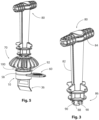
- Figure 3 illustrates an example of an extraction tool 80 operable to install and remove the assembled urinal apparatus 10 to/from a urinal outlet.
- the tool 80 is T-shaped, which includes a long shaft 82 with a head portion 84 at the upper end and a key portion 86 at the lower end.
- the key portion 86 is configured to engage with the openings 24 through the disc 23 to facilitate insertion/removal of the urinal apparatus 10 as a unit to/from the urinal outlet.
- Figure 5 illustrates the extraction tool 80 engaged with the fully assembled urinal apparatus 10.
- the key portion 86 lockingly engages with the urinal apparatus 10 by virtue of a bayonet fitting i.e, the key portion 86 includes two or more protruding elements 88, each of which includes at least one lug 90, which is insertable into a window/opening 24 and is rotated such that the lugs 90 abut material of the disc 23 surrounding the opening 24 in which the protruding element 88 is inserted.
- the extraction tool 80 can pull the urinal apparatus 10, as a unit, from the urinal outlet for replacement, maintenance etc.
- the extraction tool 80 includes three protruding elements 88, each being T-shaped with two lugs 90 extending from each protruding element 88. This arrangement means that the key portion 86 can be inserted into the holes 24 and rotated clockwise or anti-clockwise to lock together the extraction tool 80 and the urinal apparatus 10.
- the disc 23 includes three lozenge shaped holes 24 and a central hole 24' and the extraction tool 80 includes three similarly shaped protruding elements 88 with lugs 90.
- the cap 70 can be removed from the urinal apparatus 10 without removing the urinal apparatus 10 from the urinal outlet.
- the urinal apparatus 10 is removed as a single unit i.e. the assembled upper housing 14, lower housing 16, associated internal components and the cap 70 are removed by a single action using the extraction tool 80.
- FIG 4 illustrates a blade key 60 and how it is used.
- the blade key 60 is shaped like a plectrum/pick used with a stringed instrument.
- the blade key 60 is a small flat tool with an edge 92 configured for insertion into the groove 58 between the upper and lower housings 14, 16 (as described above with reference to figure 4 ) and operable to prise them apart to gain access to the adaptor 32 for removal or replacement of the deodorising/detergent block 33 (see figures 1 and 1a ) and to the duckbill valve 36 for removal/replacement.
- Figure 5 illustrates interaction of the extraction tool 80, the blade key 60, and the urinal apparatus 10.
- urine flows down the urinal walls and enters the urinal apparatus 10 over and between the fins 74, 76 of the consumable cap 70 and through the apertures/openings 24 defined in the disc 23 of the upper housing 14.
- Urine passes through the upper housing 14 in contact with the deodoriser/detergent block 33 and then through the duckbill valve 36 before exiting the apparatus 10 and through the urinal outlet.
- the assembly of the cap 70 and upper section 14 ensures the inlet of the urinal apparatus 10 is raised relative to the drain/urinal outlet to which the urinal apparatus 10 is attached.
- a grid 100 is created by the assembly.
- the grid 100 is sized sufficiently to permit undisturbed flow of urine i.e. improved fluid dynamics and to prevent foreign debris from entering the waste system.
- the urinal apparatus 10 is described as being suitable for a waterless urinal. However, it should be appreciated that the urinal apparatus 10 is equally suitable for use with a urinal that incorporates a water seal (and water flushing facility) where the resealable valve 36 e.g. a duckbill valve can extend into a trap incorporating a water seal, for example a U-bend, a bottle trap etc.
- a water seal and water flushing facility
Landscapes
- Health & Medical Sciences (AREA)
- Public Health (AREA)
- Engineering & Computer Science (AREA)
- Life Sciences & Earth Sciences (AREA)
- Hydrology & Water Resources (AREA)
- Water Supply & Treatment (AREA)
- Environmental & Geological Engineering (AREA)
- Epidemiology (AREA)
- Sanitary Device For Flush Toilet (AREA)
Claims (16)
- Eine Urinalvorrichtung (10), die zum Einführen in einen Auslass eines Urinals konfiguriert ist, wobei die Urinalvorrichtung Folgendes beinhaltet:einen hohlen Körper (12), der ein oberes Gehäuse (14) und ein unteres Gehäuse (16) definiert;ein internes verbrauchbares Detergens/Desodorierungsmittel (33);ein wieder verschließbares Ventil (36); undein extern montiertes verbrauchbares Kappenelement (70);wobei das obere Gehäuse (14) eine offene Kammer bereitstellt, die dazu konfiguriert ist, das verbrauchbare Detergens/Desodorierungsmittel (33) aufzunehmen und zu halten, und wobei das untere Gehäuse (16) dazu konfiguriert ist, das wieder verschließbare Ventil (36) zu stützen und zu halten, das wirksam ist, um den Fluss von Flüssigkeit, wie etwa Urin, von oben zu erlauben, aber wirksam ist, um den Rückfluss von unterhalb des wieder verschließbaren Ventils (36) zu verhindern; undwobei das extern montierte verbrauchbare Kappenelement (70) eine axiale Öffnung (72) mindestens teilweise hindurch umfasst, wobei die Öffnung (72) dazu konfiguriert ist, mindestens einen Teil des oberen Gehäuses (14) aufzunehmen, wobei ein Körper des Kappenelements eine Vielzahl von sich radial erstreckenden Rippen (74, 76) umfasst, wobei eines von dem oberen Gehäuse (14) oder dem verbrauchbaren Kappenelement (70) ein oberes Glied umfasst, das eine Anordnung von Löchern (24) beinhaltet, die bei Gebrauch einen Flüssigkeitsfluss durch die Vorrichtung (10) ermöglichen, und wobei die Anordnung von Löchern (24) dazu konfiguriert sind, mit einem Ausziehwerkzeug (80) zum Einführen und Herausziehen der Urinalvorrichtung (10) in ein bzw. aus einem Urinal als Einheit zu interagieren.
- Urinalvorrichtung gemäß Anspruch 1, wobei das verbrauchbare Kappenelement (70) aus duftendem Material gefertigt ist, aus dem Duftstoff emittiert wird, und bei Gebrauch im Verlauf der Zeit aufgebraucht wird, wenn Flüssigkeit, insbesondere Urin, mit dem Kappenelement (70) in Kontakt kommt.
- Urinalvorrichtung gemäß Anspruch 1 oder 2, wobei das Kappenelement (70) bei Gebrauch im Verlauf der Zeit schrumpft, wenn Flüssigkeit, insbesondere Urin, mit dem Kappenelement (70) in Kontakt kommt.
- Urinalvorrichtung gemäß Anspruch 1, 2 oder 3, wobei das verbrauchbare Kappenelement (70) aus duftendem Ethylenvinylacetat (EVA) gefertigt ist.
- Urinalvorrichtung gemäß einem der Ansprüche 1, 2, 3 oder 4, wobei sich jede Rippe (74, 76) von einem zylindrischen Mittelbereich (72) erstreckt.
- Urinalvorrichtung gemäß Anspruch 5, wobei sich die sich radial erstreckenden Rippen (74, 76) gleichmäßig erstrecken und gleichmäßig um den zylindrischen Mittelbereich (72) des verbrauchbaren Kappenelements (70) verteilt sind.
- Urinalvorrichtung gemäß Anspruch 5 oder 6, wobei jede Rippe (74, 76) im Wesentlichen dreieckig ist und mindestens eine gerade Kante beinhaltet, die durch die Verbindungsstelle jeder Rippe (74, 76) mit dem zylindrischen Mittelbereich (72) definiert wird.
- Urinalvorrichtung gemäß Anspruch 7, wobei jede Rippe (74, 76) eine oder mehrere gekrümmte Kanten und eine gerade Kante umfasst, wobei die gerade Kante durch die Verbindungsstelle jeder Rippe (74, 76) mit dem zylindrischen Mittelbereich (72) definiert wird.
- Urinalvorrichtung gemäß einem der Ansprüche 5 bis 8, wobei die verbrauchbare Kappe (70) mindestens zwei unterschiedlich bemessene Rippen (74, 76) umfasst, die alternierend um den zylindrischen Mittelbereich (72) in der Reihenfolge groß, klein, groß, klein etc. angeordnet sind, wobei die Rippen (74, 76) jeweils eine gerade Kante umfassen, die durch die Verbindungsstelle jeder Rippe (74, 76) mit dem zylindrischen Mittelbereich (72) definiert wird, und wobei große Rippen (74) eine gerade Kante umfassen, die länger als die gerade Kante der kleinen Rippen (76) ist, und wobei obere Oberflächen der großen und kleinen Rippen (74, 76) im Wesentlichen auf einer Höhe sind.
- Urinalvorrichtung gemäß Anspruch 9, wobei die Länge der geraden Kante von großen Rippen (74) dem Ausmaß der Länge des zylindrischen Mittelbereichs (72) entspricht.
- Urinalvorrichtung gemäß einem vorhergehenden Anspruch, wobei die verbrauchbare Kappe (70) dazu konfiguriert ist, sich bei Gebrauch aufzulösen und/oder bei Gebrauch als Austauschanzeige die Farbe zu ändern.
- Urinalvorrichtung gemäß einem vorhergehenden Anspruch, die eines oder mehrere von Folgendem umfasst:
wobei das obere Gehäuse (14) und untere Gehäuse (16) getrennte Elemente umfassen, die an einer Kreuzung miteinander befestigt sind, um den hohlen Körper bereitzustellen; und wobei das Miteinanderbefestigen des oberen Gehäuses (14) und unteren Gehäuses (16) durch eine Schnappmontageverbindung erfolgt. - Urinalvorrichtung gemäß einem vorhergehenden Anspruch, die eines oder mehrere von Folgendem umfasst: wobei der hohle Körper einen Adapter (32) umfasst, der in das obere Gehäuse (14) einführbar ist, wobei der Adapter (32) dazu konfiguriert ist, das verbrauchbare Detergens/Desodorierungsmittel (33) zu stützen und einen vertikalen Fluss von Flüssigkeit in das untere Gehäuse (16) und durch das wieder verschließbare Ventil (36) zu ermöglichen;
wobei das obere Gehäuse (14) das obere Glied umfasst, das die Anordnung von Löchern (24) beinhaltet; und wobei das obere Gehäuse (14) in Form eines verjüngten Zylinders vorliegt, wobei die Zylinderwand von einem oberen Ende mit kleinerem Durchmesser (23) zu einer Basis mit größerem Durchmesser (26) konisch verläuft und wobei die Wand durch durch die Wand definierte längslaufende Öffnungen/Fenster (22) in Wandbereiche (21) unterteilt wird. - Urinalvorrichtung gemäß einem der Ansprüche 11, 12 oder 13, wobei der Aufbau der verbrauchbaren Kappe (70) und des oberen Bereichs einen exponierten Rostabschnitt (100) definiert, der wirksam ist, um zu verhindern, dass Schmutz in die Urinalvorrichtung (10) und das Ablaufsystem, an dem die Urinalvorrichtung (10) angebracht ist, eindringt.
- Urinalvorrichtung gemäß einem vorhergehenden Anspruch, wobei das untere Gehäuse (16) als Spannring konfiguriert ist, der wirksam ist, um das wieder verschließbare Ventil (36) relativ zu dem oberen Gehäuse (14) einzuspannen.
- Ein Verfahren zum Installieren in und Entfernen aus einem Urinalauslass der Urinalvorrichtung (10) gemäß einem vorhergehenden Anspruch, wobei das Verfahren das Ineingriffnehmen eines Ausziehwerkzeugs (80) mit der Anordnung von Löchern (24) des oberen Glieds, das Verriegeln des Ausziehwerkzeugs (80) relativ zu dem oberen Glied und das Installieren oder Entfernen der Urinalvorrichtung (10) als einzelne Einheit umfasst.
Applications Claiming Priority (1)
| Application Number | Priority Date | Filing Date | Title |
|---|---|---|---|
| GB2000793.6A GB2582062B (en) | 2020-01-20 | 2020-01-20 | Improved urinal apparatus with consumable cap |
Publications (3)
| Publication Number | Publication Date |
|---|---|
| EP3851597A1 EP3851597A1 (de) | 2021-07-21 |
| EP3851597C0 EP3851597C0 (de) | 2023-10-04 |
| EP3851597B1 true EP3851597B1 (de) | 2023-10-04 |
Family
ID=69636824
Family Applications (1)
| Application Number | Title | Priority Date | Filing Date |
|---|---|---|---|
| EP21150353.7A Active EP3851597B1 (de) | 2020-01-20 | 2021-01-06 | Verbesserte urinalvorrichtung mit verbrauchbarer kappe |
Country Status (4)
| Country | Link |
|---|---|
| US (1) | US11219341B2 (de) |
| EP (1) | EP3851597B1 (de) |
| GB (1) | GB2582062B (de) |
| ZA (1) | ZA202100215B (de) |
Family Cites Families (9)
| Publication number | Priority date | Publication date | Assignee | Title |
|---|---|---|---|---|
| US5165119A (en) * | 1990-07-06 | 1992-11-24 | Amenity Co., Ltd. | Chemical setting receptacle for urinal scupper or the like |
| ZA200509145B (en) * | 2004-11-15 | 2006-08-30 | Caroma Ind Ltd | A removable cartridge assembly for a waterless urinal |
| EP2088252A3 (de) * | 2007-05-17 | 2013-12-18 | Personnel Hygiene Services Limited | Geruchsverschluß für ein Urinal |
| WO2009040524A1 (en) * | 2007-09-25 | 2009-04-02 | Mcalpine & Company Limited | Improved urinal apparatus |
| GB2473055B (en) * | 2009-08-28 | 2015-05-13 | Mcalpine & Co Ltd | An apparatus for masking and/or deodorising a urinal odour |
| CH702929B1 (de) * | 2010-04-01 | 2014-10-31 | Enswico Ip Ag | Vorrichtung zum Feststellen und Festlegen des Zeitpunkts für den Ersatz von Verschleissteilen an einem Sanitärapparat in Abhängigkeit der Benutzungshäufigkeit. |
| US8967176B2 (en) * | 2010-05-12 | 2015-03-03 | Blayne A. Connor | Fume blocking drain cap |
| GB2487955B (en) * | 2011-02-10 | 2016-04-27 | Personnel Hygiene Services Ltd | Urinal sanitizing device |
| US9222247B2 (en) * | 2013-03-15 | 2015-12-29 | Xela Innovations, Llc | Fixture drain insert assembly |
-
2020
- 2020-01-20 GB GB2000793.6A patent/GB2582062B/en active Active
-
2021
- 2021-01-06 EP EP21150353.7A patent/EP3851597B1/de active Active
- 2021-01-08 US US17/144,996 patent/US11219341B2/en active Active
- 2021-01-13 ZA ZA2021/00215A patent/ZA202100215B/en unknown
Also Published As
| Publication number | Publication date |
|---|---|
| US11219341B2 (en) | 2022-01-11 |
| GB202000793D0 (en) | 2020-03-04 |
| GB2582062B (en) | 2021-03-17 |
| EP3851597C0 (de) | 2023-10-04 |
| EP3851597A1 (de) | 2021-07-21 |
| US20210219796A1 (en) | 2021-07-22 |
| ZA202100215B (en) | 2023-06-28 |
| GB2582062A (en) | 2020-09-09 |
Similar Documents
| Publication | Publication Date | Title |
|---|---|---|
| US8943619B2 (en) | Trap assembly for a hybrid wall urinal and associated methods | |
| US7246386B2 (en) | Waste outlet assembly | |
| CZ2000358A3 (cs) | Odpadní zařízení | |
| EP3134585B1 (de) | Schwerkraftventil | |
| US7636957B2 (en) | Urinal | |
| CN101297085B (zh) | 具有防溢流特征的用于清除身体废物的设备及其制造方法 | |
| GB2473055A (en) | Urinal apparatus | |
| US11219341B2 (en) | Urinal apparatus with consumable cap | |
| DK2627835T3 (en) | Urinal and method for the replacement of an odor seal of a urinal | |
| US20020112279A1 (en) | Odour extraction system for a toilet, urinal, bidet, and the like | |
| US10077546B2 (en) | Cartridge for a urinal outlet | |
| JP6522117B2 (ja) | サニタリーバルブ装置およびサニタリーバルブアセンブリ | |
| EP1629159B1 (de) | System zur entfernung von gerüchen mit einem in einem flüssigkeitsbehälter enthaltenen ventil | |
| KR200445016Y1 (ko) | 배수트랩 | |
| WO2006021819A1 (en) | Waste outlet assembly | |
| WO2018189753A1 (en) | Odor prevention sanitary plumbing fitting, system and method | |
| JP3190162U (ja) | 臭気を遮断しながら廃液を排出するための排水トラップアセンブリ | |
| SG193644A1 (en) | Chemical & oil-free waterless urinal valve | |
| JPH07305392A (ja) | 便器排水系統の異物検出装置 | |
| AU2307201A (en) | An odour extraction system for a toilet, urinal, bidet, and the like |
Legal Events
| Date | Code | Title | Description |
|---|---|---|---|
| PUAI | Public reference made under article 153(3) epc to a published international application that has entered the european phase |
Free format text: ORIGINAL CODE: 0009012 |
|
| STAA | Information on the status of an ep patent application or granted ep patent |
Free format text: STATUS: THE APPLICATION HAS BEEN PUBLISHED |
|
| AK | Designated contracting states |
Kind code of ref document: A1 Designated state(s): AL AT BE BG CH CY CZ DE DK EE ES FI FR GB GR HR HU IE IS IT LI LT LU LV MC MK MT NL NO PL PT RO RS SE SI SK SM TR |
|
| STAA | Information on the status of an ep patent application or granted ep patent |
Free format text: STATUS: REQUEST FOR EXAMINATION WAS MADE |
|
| 17P | Request for examination filed |
Effective date: 20210727 |
|
| RBV | Designated contracting states (corrected) |
Designated state(s): AL AT BE BG CH CY CZ DE DK EE ES FI FR GB GR HR HU IE IS IT LI LT LU LV MC MK MT NL NO PL PT RO RS SE SI SK SM TR |
|
| GRAP | Despatch of communication of intention to grant a patent |
Free format text: ORIGINAL CODE: EPIDOSNIGR1 |
|
| STAA | Information on the status of an ep patent application or granted ep patent |
Free format text: STATUS: GRANT OF PATENT IS INTENDED |
|
| INTG | Intention to grant announced |
Effective date: 20230110 |
|
| GRAJ | Information related to disapproval of communication of intention to grant by the applicant or resumption of examination proceedings by the epo deleted |
Free format text: ORIGINAL CODE: EPIDOSDIGR1 |
|
| STAA | Information on the status of an ep patent application or granted ep patent |
Free format text: STATUS: REQUEST FOR EXAMINATION WAS MADE |
|
| GRAP | Despatch of communication of intention to grant a patent |
Free format text: ORIGINAL CODE: EPIDOSNIGR1 |
|
| STAA | Information on the status of an ep patent application or granted ep patent |
Free format text: STATUS: GRANT OF PATENT IS INTENDED |
|
| INTC | Intention to grant announced (deleted) | ||
| RBV | Designated contracting states (corrected) |
Designated state(s): AL AT BE BG CH CY CZ DE DK EE ES FI FR GR HR HU IE IS IT LI LT LU LV MC MK MT NL NO PL PT RO RS SE SI SK SM TR |
|
| RIN1 | Information on inventor provided before grant (corrected) |
Inventor name: MARSHALL, SEBASTIAN NIKOLAI JONATHAN Inventor name: MCLEAN, JAMES EDWARD |
|
| INTG | Intention to grant announced |
Effective date: 20230512 |
|
| GRAS | Grant fee paid |
Free format text: ORIGINAL CODE: EPIDOSNIGR3 |
|
| GRAA | (expected) grant |
Free format text: ORIGINAL CODE: 0009210 |
|
| STAA | Information on the status of an ep patent application or granted ep patent |
Free format text: STATUS: THE PATENT HAS BEEN GRANTED |
|
| AK | Designated contracting states |
Kind code of ref document: B1 Designated state(s): AL AT BE BG CH CY CZ DE DK EE ES FI FR GR HR HU IE IS IT LI LT LU LV MC MK MT NL NO PL PT RO RS SE SI SK SM TR |
|
| REG | Reference to a national code |
Ref country code: CH Ref legal event code: EP |
|
| REG | Reference to a national code |
Ref country code: IE Ref legal event code: FG4D |
|
| REG | Reference to a national code |
Ref country code: DE Ref legal event code: R096 Ref document number: 602021005505 Country of ref document: DE |
|
| U01 | Request for unitary effect filed |
Effective date: 20231027 |
|
| U07 | Unitary effect registered |
Designated state(s): AT BE BG DE DK EE FI FR IT LT LU LV MT NL PT SE SI Effective date: 20231102 |
|
| U20 | Renewal fee for the european patent with unitary effect paid |
Year of fee payment: 4 Effective date: 20240125 |
|
| PG25 | Lapsed in a contracting state [announced via postgrant information from national office to epo] |
Ref country code: GR Free format text: LAPSE BECAUSE OF FAILURE TO SUBMIT A TRANSLATION OF THE DESCRIPTION OR TO PAY THE FEE WITHIN THE PRESCRIBED TIME-LIMIT Effective date: 20240105 |
|
| PG25 | Lapsed in a contracting state [announced via postgrant information from national office to epo] |
Ref country code: IS Free format text: LAPSE BECAUSE OF FAILURE TO SUBMIT A TRANSLATION OF THE DESCRIPTION OR TO PAY THE FEE WITHIN THE PRESCRIBED TIME-LIMIT Effective date: 20240204 |
|
| PG25 | Lapsed in a contracting state [announced via postgrant information from national office to epo] |
Ref country code: ES Free format text: LAPSE BECAUSE OF FAILURE TO SUBMIT A TRANSLATION OF THE DESCRIPTION OR TO PAY THE FEE WITHIN THE PRESCRIBED TIME-LIMIT Effective date: 20231004 |
|
| PG25 | Lapsed in a contracting state [announced via postgrant information from national office to epo] |
Ref country code: IS Free format text: LAPSE BECAUSE OF FAILURE TO SUBMIT A TRANSLATION OF THE DESCRIPTION OR TO PAY THE FEE WITHIN THE PRESCRIBED TIME-LIMIT Effective date: 20240204 Ref country code: GR Free format text: LAPSE BECAUSE OF FAILURE TO SUBMIT A TRANSLATION OF THE DESCRIPTION OR TO PAY THE FEE WITHIN THE PRESCRIBED TIME-LIMIT Effective date: 20240105 Ref country code: ES Free format text: LAPSE BECAUSE OF FAILURE TO SUBMIT A TRANSLATION OF THE DESCRIPTION OR TO PAY THE FEE WITHIN THE PRESCRIBED TIME-LIMIT Effective date: 20231004 |
|
| PG25 | Lapsed in a contracting state [announced via postgrant information from national office to epo] |
Ref country code: RS Free format text: LAPSE BECAUSE OF FAILURE TO SUBMIT A TRANSLATION OF THE DESCRIPTION OR TO PAY THE FEE WITHIN THE PRESCRIBED TIME-LIMIT Effective date: 20231004 Ref country code: PL Free format text: LAPSE BECAUSE OF FAILURE TO SUBMIT A TRANSLATION OF THE DESCRIPTION OR TO PAY THE FEE WITHIN THE PRESCRIBED TIME-LIMIT Effective date: 20231004 Ref country code: NO Free format text: LAPSE BECAUSE OF FAILURE TO SUBMIT A TRANSLATION OF THE DESCRIPTION OR TO PAY THE FEE WITHIN THE PRESCRIBED TIME-LIMIT Effective date: 20240104 Ref country code: HR Free format text: LAPSE BECAUSE OF FAILURE TO SUBMIT A TRANSLATION OF THE DESCRIPTION OR TO PAY THE FEE WITHIN THE PRESCRIBED TIME-LIMIT Effective date: 20231004 |
|
| REG | Reference to a national code |
Ref country code: DE Ref legal event code: R097 Ref document number: 602021005505 Country of ref document: DE |
|
| PG25 | Lapsed in a contracting state [announced via postgrant information from national office to epo] |
Ref country code: CZ Free format text: LAPSE BECAUSE OF FAILURE TO SUBMIT A TRANSLATION OF THE DESCRIPTION OR TO PAY THE FEE WITHIN THE PRESCRIBED TIME-LIMIT Effective date: 20231004 |
|
| PG25 | Lapsed in a contracting state [announced via postgrant information from national office to epo] |
Ref country code: SK Free format text: LAPSE BECAUSE OF FAILURE TO SUBMIT A TRANSLATION OF THE DESCRIPTION OR TO PAY THE FEE WITHIN THE PRESCRIBED TIME-LIMIT Effective date: 20231004 |
|
| PG25 | Lapsed in a contracting state [announced via postgrant information from national office to epo] |
Ref country code: SM Free format text: LAPSE BECAUSE OF FAILURE TO SUBMIT A TRANSLATION OF THE DESCRIPTION OR TO PAY THE FEE WITHIN THE PRESCRIBED TIME-LIMIT Effective date: 20231004 Ref country code: SK Free format text: LAPSE BECAUSE OF FAILURE TO SUBMIT A TRANSLATION OF THE DESCRIPTION OR TO PAY THE FEE WITHIN THE PRESCRIBED TIME-LIMIT Effective date: 20231004 Ref country code: RO Free format text: LAPSE BECAUSE OF FAILURE TO SUBMIT A TRANSLATION OF THE DESCRIPTION OR TO PAY THE FEE WITHIN THE PRESCRIBED TIME-LIMIT Effective date: 20231004 Ref country code: CZ Free format text: LAPSE BECAUSE OF FAILURE TO SUBMIT A TRANSLATION OF THE DESCRIPTION OR TO PAY THE FEE WITHIN THE PRESCRIBED TIME-LIMIT Effective date: 20231004 |
|
| PLBE | No opposition filed within time limit |
Free format text: ORIGINAL CODE: 0009261 |
|
| STAA | Information on the status of an ep patent application or granted ep patent |
Free format text: STATUS: NO OPPOSITION FILED WITHIN TIME LIMIT |
|
| PG25 | Lapsed in a contracting state [announced via postgrant information from national office to epo] |
Ref country code: MC Free format text: LAPSE BECAUSE OF FAILURE TO SUBMIT A TRANSLATION OF THE DESCRIPTION OR TO PAY THE FEE WITHIN THE PRESCRIBED TIME-LIMIT Effective date: 20231004 |
|
| PG25 | Lapsed in a contracting state [announced via postgrant information from national office to epo] |
Ref country code: MC Free format text: LAPSE BECAUSE OF FAILURE TO SUBMIT A TRANSLATION OF THE DESCRIPTION OR TO PAY THE FEE WITHIN THE PRESCRIBED TIME-LIMIT Effective date: 20231004 |
|
| REG | Reference to a national code |
Ref country code: CH Ref legal event code: PL |
|
| 26N | No opposition filed |
Effective date: 20240705 |
|
| PG25 | Lapsed in a contracting state [announced via postgrant information from national office to epo] |
Ref country code: CH Free format text: LAPSE BECAUSE OF NON-PAYMENT OF DUE FEES Effective date: 20240131 |
|
| PG25 | Lapsed in a contracting state [announced via postgrant information from national office to epo] |
Ref country code: CH Free format text: LAPSE BECAUSE OF NON-PAYMENT OF DUE FEES Effective date: 20240131 |
|
| PG25 | Lapsed in a contracting state [announced via postgrant information from national office to epo] |
Ref country code: IE Free format text: LAPSE BECAUSE OF NON-PAYMENT OF DUE FEES Effective date: 20240106 |
|
| PG25 | Lapsed in a contracting state [announced via postgrant information from national office to epo] |
Ref country code: IE Free format text: LAPSE BECAUSE OF NON-PAYMENT OF DUE FEES Effective date: 20240106 |
|
| U20 | Renewal fee for the european patent with unitary effect paid |
Year of fee payment: 5 Effective date: 20250129 |
|
| PG25 | Lapsed in a contracting state [announced via postgrant information from national office to epo] |
Ref country code: CY Free format text: LAPSE BECAUSE OF FAILURE TO SUBMIT A TRANSLATION OF THE DESCRIPTION OR TO PAY THE FEE WITHIN THE PRESCRIBED TIME-LIMIT; INVALID AB INITIO Effective date: 20210106 |
|
| PG25 | Lapsed in a contracting state [announced via postgrant information from national office to epo] |
Ref country code: HU Free format text: LAPSE BECAUSE OF FAILURE TO SUBMIT A TRANSLATION OF THE DESCRIPTION OR TO PAY THE FEE WITHIN THE PRESCRIBED TIME-LIMIT; INVALID AB INITIO Effective date: 20210106 |
|
| PG25 | Lapsed in a contracting state [announced via postgrant information from national office to epo] |
Ref country code: TR Free format text: LAPSE BECAUSE OF FAILURE TO SUBMIT A TRANSLATION OF THE DESCRIPTION OR TO PAY THE FEE WITHIN THE PRESCRIBED TIME-LIMIT Effective date: 20231004 |
|
| U20 | Renewal fee for the european patent with unitary effect paid |
Year of fee payment: 6 Effective date: 20260129 |