EP3851591A2 - Working machine and program update system for working machine - Google Patents
Working machine and program update system for working machine Download PDFInfo
- Publication number
- EP3851591A2 EP3851591A2 EP20208347.3A EP20208347A EP3851591A2 EP 3851591 A2 EP3851591 A2 EP 3851591A2 EP 20208347 A EP20208347 A EP 20208347A EP 3851591 A2 EP3851591 A2 EP 3851591A2
- Authority
- EP
- European Patent Office
- Prior art keywords
- update
- working
- program
- machine body
- controller
- Prior art date
- Legal status (The legal status is an assumption and is not a legal conclusion. Google has not performed a legal analysis and makes no representation as to the accuracy of the status listed.)
- Granted
Links
Images





Classifications
-
- G—PHYSICS
- G06—COMPUTING OR CALCULATING; COUNTING
- G06F—ELECTRIC DIGITAL DATA PROCESSING
- G06F8/00—Arrangements for software engineering
- G06F8/60—Software deployment
- G06F8/65—Updates
-
- E—FIXED CONSTRUCTIONS
- E02—HYDRAULIC ENGINEERING; FOUNDATIONS; SOIL SHIFTING
- E02F—DREDGING; SOIL-SHIFTING
- E02F9/00—Component parts of dredgers or soil-shifting machines, not restricted to one of the kinds covered by groups E02F3/00 - E02F7/00
- E02F9/20—Drives; Control devices
- E02F9/2025—Particular purposes of control systems not otherwise provided for
-
- E—FIXED CONSTRUCTIONS
- E02—HYDRAULIC ENGINEERING; FOUNDATIONS; SOIL SHIFTING
- E02F—DREDGING; SOIL-SHIFTING
- E02F3/00—Dredgers; Soil-shifting machines
- E02F3/04—Dredgers; Soil-shifting machines mechanically-driven
- E02F3/96—Dredgers; Soil-shifting machines mechanically-driven with arrangements for alternate or simultaneous use of different digging elements
-
- E—FIXED CONSTRUCTIONS
- E02—HYDRAULIC ENGINEERING; FOUNDATIONS; SOIL SHIFTING
- E02F—DREDGING; SOIL-SHIFTING
- E02F9/00—Component parts of dredgers or soil-shifting machines, not restricted to one of the kinds covered by groups E02F3/00 - E02F7/00
- E02F9/26—Indicating devices
-
- G—PHYSICS
- G06—COMPUTING OR CALCULATING; COUNTING
- G06F—ELECTRIC DIGITAL DATA PROCESSING
- G06F9/00—Arrangements for program control, e.g. control units
- G06F9/06—Arrangements for program control, e.g. control units using stored programs, i.e. using an internal store of processing equipment to receive or retain programs
- G06F9/44—Arrangements for executing specific programs
- G06F9/4401—Bootstrapping
- G06F9/4411—Configuring for operating with peripheral devices; Loading of device drivers
-
- B—PERFORMING OPERATIONS; TRANSPORTING
- B60—VEHICLES IN GENERAL
- B60K—ARRANGEMENT OR MOUNTING OF PROPULSION UNITS OR OF TRANSMISSIONS IN VEHICLES; ARRANGEMENT OR MOUNTING OF PLURAL DIVERSE PRIME-MOVERS IN VEHICLES; AUXILIARY DRIVES FOR VEHICLES; INSTRUMENTATION OR DASHBOARDS FOR VEHICLES; ARRANGEMENTS IN CONNECTION WITH COOLING, AIR INTAKE, GAS EXHAUST OR FUEL SUPPLY OF PROPULSION UNITS IN VEHICLES
- B60K17/00—Arrangement or mounting of transmissions in vehicles
- B60K17/28—Arrangement or mounting of transmissions in vehicles characterised by arrangement, location, or type of power take-off
-
- B—PERFORMING OPERATIONS; TRANSPORTING
- B60—VEHICLES IN GENERAL
- B60Y—INDEXING SCHEME RELATING TO ASPECTS CROSS-CUTTING VEHICLE TECHNOLOGY
- B60Y2200/00—Type of vehicle
- B60Y2200/20—Off-Road Vehicles
- B60Y2200/22—Agricultural vehicles
-
- B—PERFORMING OPERATIONS; TRANSPORTING
- B60—VEHICLES IN GENERAL
- B60Y—INDEXING SCHEME RELATING TO ASPECTS CROSS-CUTTING VEHICLE TECHNOLOGY
- B60Y2200/00—Type of vehicle
- B60Y2200/40—Special vehicles
- B60Y2200/41—Construction vehicles, e.g. graders, excavators
Definitions
- the present invention relates to a working machine and to a program update system for the working machine such as an agriculture machine and a construction machine.
- Patent Document 1 is known as a system for writing an update program of a working machine.
- the program updating method includes steps of preliminarily setting data for checking a computer program of the controller device for the working machine, erasing data to be used to check an existing computer program preliminarily stored in the controller device before the update program is written to the controller device for the working machine, and then writing the update program to the controller device for the working machine and writing data to be used to check the update program lastly to the controller device for the working machine.
- Patent Document 1 Japanese Unexamined Patent Publication No. 2010-176372
- Patent Document 1 is very useful because it allows an update program to be properly written to a controller device installed in a working machine. However, Patent Document 1 does not consider updating the update program of the working machine, that is, another working device connected to the vehicle body.
- the present invention intends to provide a communication system for a working machine capable of easily updating an update program of a working device connected to the machine body.
- a program update system for a working machine includes: a machine body; a working device to be used for work, the working device being provided to the machine body; a storage device to store an update program for the machine body or the working device; and an update controller to control the update program.
- the update controller executes the update program for the working device based on a state of the machine body or the working device.
- the program update system for the working machine mentioned above includes a positioning device to detect a position of the machine body.
- the update controller executes the update program when the position detected by the positioning device is a parking area of the machine body.
- the update controller judges whether the machine body is in being transported based on the position, and executes the update program when the machine body is in being transported.
- the machine body includes a power transmission device to transmit power to the working device, and the update controller executes the update program when the power transmission device is free from transmitting power to the working device.
- the machine body includes a power transmission device to transmit power to the working device, and the update controller executes the update program after the power transmission device stops transmitting power to the working device.
- the machine body includes a lifter device to lift the working device, and the update controller executes the update program when the lifter device is free from lifting the working device.
- the program update system for the working machine mentioned above includes a timer to count time.
- the update controller judges whether the working device is in a period free from being used based on the time counted by the timer and identification information of the working device, and executes the update program in the period free from being used.
- a working machine includes: a machine body to be connected to a working machine; an in-vehicle network provided to the machine body; a machine body controller to control the machine body; an update controller to control an update program of the working device; a first connector to be connected to the in-vehicle network, the first connector being provided to the machine body; and a notifier to issue notification when the update controller transmits the update program to the in-vehicle network under a state where a communication cable of the working device is connected to the first connector.
- the working machine mentioned above includes: a communicator to receive the update program from outside; and a storage device to store the update program for the working device.
- the update controller stores the update program received by the communicator to the storage device, and then transmits the update program stored in the storage device to the in-vehicle network after the communicator completes receiving the update program.
- the working machine mentioned above includes a plurality of electric components connected to the in-vehicle network.
- the update controller distributes the update program to the plurality of electric components.
- the notifier is a lamp provided to the machine body and configured to be lighted to issue notification that represents the update program is in being executed.
- the notifier is a speaker provided to the machine body and configured to output sounds to issue notification that represents the update program is in being executed.
- the notifier issues notification representing other than the execution of the update program when the communication cable is disconnected from the first connector.
- the update controller issues the notification to a mobile terminal.
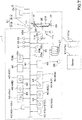
- FIG. 3 shows a control block of working machine 1 and a communication system of working machine 1.
- the working machine 1 is an agricultural machine such as a tractor, a combine, a rice planter, and the like, and a construction machine such as a loader and a backhoe.
- the working machine will be described below, taking the tractor as an example.
- the working machine 1 is not limited to the tractor, and therefore, the configuration common to agricultural machinery such as a combine, a rice planter, and the like, and a construction machine such as a loader and a backhoe can be replaced. That is, the description of the tractor can be read as other agricultural and construction machinery.
- the tractor is provided with a machine body 3 having a traveling device 7, a prime mover 4, and a speed-shifter device 5.
- the traveling device 7 is a device having a front wheel 7F and a rear wheel 7R.
- the front wheels 7F may be of the tire or crawler type.
- the rear wheels 7R may also be of the tire or crawler type.
- the prime mover 4 is a gasoline engine, an internal combustion engine such as a diesel engine, an electric motor, and the like. In this embodiment, the prime mover 4 is a diesel engine.
- the speed-shifter device 5 is capable of switching the propulsion of the traveling device 7 by shifting gears and of switching the traveling device 7 forward or backward.
- a cabin 9 is provided in the machine body 3, and an operator seat 10 is provided in the cabin 9.
- a coupler portion 8 is provided at the rear portion of the machine body 3.
- the coupler portion 8 is detachable with the working device 2.
- the coupler portion 8 is a lifter device that raises and lowers the attached working device 2.
- the working device 2 includes a cultivating device for cultivating, a fertilizer sprayer device for spraying fertilizer, a pesticide sprayer device for spraying pesticides, a harvester device for harvesting, a mower device for harvesting pastures and the like, a tedder device for diffusing pastures and the like, a grass rake for collecting pastures and the like, a baler device for molding pastures and the like.
- the working device 2 is provided with a work controller device (controller device) 2a.
- the work controller device 2a is a device for various controls of the working device 2, and includes a CPU, electrical and electronic circuits, and the like.
- the work controller device 2a has a storage device 2b for storing various information, for example, a control program, identification information, and the like.
- the storage device 2b includes a non-volatile memory or the like.
- the speed-shifter device 5 includes a main shaft (propulsion shaft) 5a, a shuttle portion 5b, a main speed-shifter portion 5c, a sub speed-shifter portion 5d, a PTO power speed-shifter portion 5e, and a front speed-shifter portion 5f.
- the propulsion shaft 5a is rotatably supported in the housing case of the speed-shifter device 5, and power from the crankshaft of the prime mover 4 is transmitted to the propulsion shaft 5a.
- the shuttle portion 5b has a shuttle shaft 5b1 and a forward/backward switching portion 5b2.
- the power from the propulsion shaft 5a is transmitted to the shuttle shaft 5b1.
- the forward/backward switching portion 5b2 includes, for example, a hydraulic clutch or the like, and switches the direction of rotation of the shuttle shaft 5b1, that is, forward and backward movement of the tractor, by turning the hydraulic clutch on and off.
- the main speed-shifter portion 5c is a stepless transmission mechanism that changes the input power to stepless.
- the stepless transmission mechanism has a hydraulic pump 5c1, a hydraulic motor 5c2, and a planetary gear mechanism 5c3.
- the hydraulic pump 5c1 is rotated by power from the output shaft 5b3 of the shuttle portion 5b.
- the hydraulic pump 5c1 is, for example, a variable displacement pump having a swash plate 12, and by changing the angle of the swash plate 12 (a swash plate angle), the flow rate of hydraulic fluid output from the hydraulic pump 5c1 can be changed.
- the hydraulic motor 5c2 is a motor that is rotated by the hydraulic fluid output from the hydraulic pump 5c1 through a piping or other fluid circuit.
- the number of revolutions of the hydraulic motor 5c2 can be changed by changing the swash plate angle of the hydraulic pump 5c1 or by changing the power input to the hydraulic pump 5c1.
- the planetary gear mechanism 5c3 is a mechanism including a plurality of gears (gears) and a power transmission shaft such as an input shaft and an output shaft, and includes an input shaft 13, wherein the power of the hydraulic pump 5c1 is input, an input shaft 14, wherein the power of the hydraulic motor 5c2 is input, and an output shaft 15, wherein the power is output.
- the planetary gear mechanism 5c3 combines the power of the hydraulic pump 5c1 and the power of the hydraulic motor 5c2 and transmits the combined power to the output shaft 15.
- the power output to the sub speed-shifter portion 5d can be changed by changing the swash plate angle of the swash plate 12 of the hydraulic pump 5c1, the number of revolutions of the prime mover 4, and the like, according to the main speed-shifter portion 5c.
- the main speed-shifter portion 5c includes a stepless transmission mechanism
- the main speed-shifter portion 5c may be a stepless transmission mechanism in which gears are used to change the speed.
- the sub speed-shifter portion 5d is a transmission mechanism having a plurality of stepped gears (gears) for changing the power, and by changing the connection (engagement) of the plurality of gears accordingly, the power input to the sub speed-shifter portion 5d from the output shaft 15 of the planetary gear mechanism 5c3 is changed and output (shifting).
- the sub speed-shifter portion 5d includes an input shaft 5d1, a first speed-shifter clutch 5d2, a second speed-shifter clutch 5d3, and an output shaft 5d4.
- the input shaft 5d1 is a shaft to which the power of the output shaft 15 of the planetary gear mechanism 5c3 is input, and inputs the input power to the first speed-shifter clutch 5d2 and the second speed-shifter clutch 5d3 via gears and the like. By switching the connection and disconnection of the first speed-shifter clutch 5d2 and the second speed-shifter clutch 5d3, the input power is changed and output to the output shaft 5d4.
- the power output to the output shaft 5d4 is transmitted to the rear wheel differential device 20R.
- the rear wheel differential device 20R rotatably supports the rear axle 21R on which the rear wheels 7R are mounted.
- the PTO power speed-shifter device 5e has a PTO clutch 5el, a PTO propulsion shaft 5e2, and a PTO speed-shifter device 5e3.
- the PTO clutch 5e1 is constituted of a hydraulic clutch or the like, and is configured to switch by turning the hydraulic clutch on and off between a state where the power of the propulsion shaft 5a is transmitted to the PTO propulsion shaft 5e2 (an engaged state) and a state where the power of the propulsion shaft 5a is not transmitted to the PTO propulsion shaft 5e2 (a disengaged state).
- the PTO speed-shifter portion 5e3 includes a speed-shifter clutch and a plurality of gears, and outputs the power (speed) input from the PTO propulsion shaft 5e2 to the PTO speed-shifter portion 5e3 by changing the power (speed).
- the front speed-shifter portion 5f has a first front speed-shifter clutch 5fl and a second front speed-shifter clutch 5f2.
- the first and second front speed-shifter clutches 5f1 and 5f2 are capable of transmitting power from the sub-speed speed-shifter portion 5d, for example, the power of the output shaft 5d4 is transmitted via the gear and the transmission shaft.
- the power from the first and second front speed-shifter clutches 5f1 and 5f2 can be transmitted to the front axle 21F via the front transmission shaft 22.
- the front transmission shaft 22 is connected to the front wheel differential device 20F, and the front wheel differential device 20F rotatably supports the front axle 21F to which the front wheels 7F are attached.
- the first front speed-shifter clutch 5f1 and the second front speed-shifter clutch 5f2 include a hydraulic clutch or the like.
- a fluid line is connected to the first front speed-shifter clutch 5f1, and the fluid line is connected to a control valve 23 to which hydraulic fluid output from the hydraulic pump is supplied.
- the first front speed-shifter clutch 5f1 is switched between an engaged state and a disengaged state according to the degree of opening of the control valve 23.
- a fluid line is connected to the second front speed-shifter clutch 5f2, and the fluid line is connected to the control valve 24.
- the second front speed-shifter clutch 5f2 is switched between to an engaged state and a disengaged state by opening the control valve 24.
- the control valve 23 and the control valve 24 are, for example, a two-position switching valve with a solenoid valve, which is switched between the engaged state and the disengaged state by magnetization or demagnetization of the solenoid valve.
- the lifter device (coupler portion) 8 has a lift arm 8a, a lower link 8b, a top link 8c, a lift rod 8d, and a lift cylinder 8e.
- the front end portion of the lift arm 8a is pivotally supported upwardly or downwardly in the upper rear portion of the case (transmission case) housing the speed-shifter device 5.
- the lift arm 8a is pivoted (raised or lowered) by the actuation of the lift cylinder 8e.
- the lift cylinder 8e includes a hydraulic cylinder.
- the lift cylinder 8e is connected to a hydraulic pump via a control valve 34.
- the control valve 34 is a solenoid valve or the like, which stretches and shortens the lift cylinder 8e.
- the front end portion of the lower link 8b is pivotally supported upwardly or downwardly in the rear lower portion of the speed-shifter device 5.
- the front end portion of the top link 8c is pivotally supported upwardly or downwardly on the rear portion of the speed-shifter device 5 above the lower link 8b.
- a lift rod 8d connects the lift arm 8a to the lower link 8b.
- a working device 2 is connected to the rear portion of the lower link 8b and the rear portion of the top link 8c.
- a posture changer device 25 is provided in the lifter device 8.
- the posture changer device 25 is a device for changing the posture of the working device 2 mounted on the machine body 3.
- the posture changer device 25 has a changer cylinder 25a including a hydraulic cylinder and a control valve 25b.
- the changer cylinder 25a is connected to the hydraulic pump via a control valve 25b.
- the control valve 25b is a solenoid valve or the like to extend and retract the changer cylinder 25a.
- the changer cylinder 25a connects the lift arm 8a to the lower link 8b.
- the tractor has a plurality of hydraulic control valves 27.
- the plurality of hydraulic control valves 27 are hydraulic switching valves to which hydraulic fluid is supplied from the hydraulic pump 28.
- the plurality of hydraulic control valves 27 each have output ports, and a hydraulic hose or the like can be connected to any of the output ports.
- the hydraulic hoses connected to any of the output ports of the hydraulic control valves 27 can be connected to the hydraulic attachments of the working device 2 to operate the various hydraulic attachments attached to the working device 2.
- the steering device 11 has a steering wheel (steering wheel) 11a, a rotating shaft (steering axis) 11b that rotates with the rotation of the steering wheel 11a, and an assist mechanism (power steering mechanism) 11c that assists the steering of the steering wheel 11a.
- a steering wheel steering wheel
- a rotating shaft steering axis
- an assist mechanism power steering mechanism
- the assist mechanism 11c includes a control valve 35 and a steering cylinder 32.
- the control valve 35 is, for example, a three-position switching valve that can be switched by movement of a spool or the like.
- the control valve 35 can also be switched by steering the steering shaft 11B.
- the steering cylinder 32 is connected to an arm (knuckle arm) 36, which changes the direction of the front wheels 7F.
- the switching position and opening degree of the control valve 35 is switched according to the handle 11a, and the steering direction of the front wheels 7F can be changed by telescoping the steering cylinder 32 to the left or right according to the switching position and opening degree of the control valve 35.
- the steering device 11 described above is an example and is not limited to the configuration described above.
- the tractor is provided with a plurality of detector devices 41.
- the plurality of detector devices 41 are devices for detecting a condition of the tractor.
- the plurality of detector devices 41 include, for example, a water temperature sensor 41a for detecting the water temperature, a fuel sensor 41b for detecting the remaining amount of fuel, a prime mover revolutions sensor (rotation sensor) 41c for detecting the number of revolutions of the prime mover 4, an accelerator pedal sensor 41d for detecting the amount of operation of the accelerator pedal, a steering angle sensor 41 e for detecting the steering angle of the steering device 11, an angle sensor 41f for detecting the angle of the lift arm 8a, a tilt detector sensor 41g for detecting the tilt of the machine body 3 in the width direction (right or left), a speed sensor 41h for detecting the speed of the machine body 3, a PTO rotation sensor (rotation sensor) 41i for detecting the number of rotations of the PTO axis, a battery sensor 41j for detecting the voltage of the storage batteries of the machine body
- the positioning device 41k is capable of detecting its own position (positioning information including latitude and longitude) by a satellite positioning system (positioning satellites) such as D-GPS, GPS, GLONASS, HOKUTO, GALILEO, and MICHIBIKI.
- a satellite positioning system positioning satellites
- the positioning device 41k receives a satellite signal transmitted from the positioning satellite (position of the positioning satellite, transmission time, correction information, and the like) and detects the position (for example, latitude and longitude) of the tractor 1, that is, the body position, based on the satellite signal.
- the positioning device 41k has a receiver device and an Inertial Measurement Unit (IMU).
- the receiver device is a device having an antenna or the like to receive satellite signals transmitted from a positioning satellite and is attached to the machine body 3 separately from the inertial measurement device.
- the receiver device is attached to the machine body 3.
- the attachment point of the receiver device is not limited to the embodiment.
- the inertial measurement device has an acceleration sensor to detect acceleration, a gyro sensor to detect angular velocity, and the like.
- the machine body 3 for example, is installed below the operator seat 10, and the roll angle, pitch angle, yaw angle, and the like of the machine body 3 can be detected by the inertial measurement device.
- the speed sensor 41h detects the vehicle speed by converting, for example, the number of rotations of the front axle 21F, the number of rotations of the rear axle 21R, the number of rotations of the front wheels 7F, the number of rotations of the rear wheels 7R, and the like into vehicle speed.
- the speed sensor 41h can also detect the directions of rotations of the front axle 21F, the rear axle 21R, the front wheels 7F and the rear wheels 7R, and can also detect whether the tractor (machine body 3) is moving forward or backward.
- the detector device 41 described above is an example and is not limited to the sensors described above.
- the tractor is also provided with a plurality of operating members (controller devices) 42.
- the plurality of operation members 42 include a shuttle lever 42a for switching the forward or backward movement of the machine body 3, an ignition switch 42b for starting the prime mover 4 and the like, a PTO speed-shifter lever 42c for setting the number of revolutions of the PTO shaft, a speed-shifter change switch 42d for switching between automatic speed-shifting and manual speed-shifting, a speed-shifter lever 42e to manually switch speed-shifting steps (speed-shifting level) of the speed-shifter device 5, the accelerator 42f to accelerate or decelerate the vehicle speed, a one-touch switch 42g to raise or lower the lifter device 8, a height setting dial 42h for setting the upper limit of the lifter device 8, a vehicle speed lever 42i for setting the vehicle speed, a hydraulic operation tool 42j, a revolutions setting tool 42k for setting the upper limit of the revolutions speed of the prime mover, and the like.
- the setting tools such as the speed-shifter change switch 42d, the height setting dial 42h, and the revolutions setting tool 42k are provided in a console box on the side of the operator seat 10.
- the operation of the machine body 3 can be set by the operator by operating the setting tools (the speed-shifter change switch 42d, the height setting dial 42h, and the revolutions setting tool 42k).
- the operation members 42 described above are an example and are not limited to those described above.
- the tractor has a plurality of machine body controller devices 40.
- the machine body controller device 40 is a device that performs various controls of the tractor (machine body 3) and includes a CPU, electrical and electronic circuits, or the like.
- the machine body controller device 40 has a storage device 43 that stores various information, for example, a control program, identification information, and the like.
- the storage device 43 includes a non-volatile memory or the like. That is, the plurality of machine body controller devices 40 are electrical components provided with the storage device 43.
- the plurality of machine body controller devices 40 include a speed-shifting controller device 40A, an engine controller device 40B, a PTO controller device 40C, an lifting controller device 40D, an automatic steering controller device 40E, an posture controller device 40F, and an assist hydraulic controller device 40G.
- the controller device 40 need not include all of the speed-shifting controller device 40A, the engine controller device 40B, the PTO controller device 40C, the lifting controller device 40D, the automatic steering controller device 40E, the posture controller device 40F, and the assist hydraulic controller device 40G, and may be provided according to the specifications of the tractor.
- the speed-shifting controller device 40A, the engine controller device 40B, the PTO controller device 40C, the lifting controller device 40D, the automatic steering controller device 40E, the posture controller device 40F and the assist hydraulic controller device 40G may be provided in an integrated controller device.
- the speed-shifting controller device 40A executes the speed shifting control.
- the speed shifting control when the automatic speed shifting function is enabled, one of the main speed-shifter portion 5c and the sub speed-shifter portion 5d are automatically switched according to the condition of the tractor, and the speed shifting step (speed shifting level) of the speed-shifter device 5 is automatically changed to a predetermined speed shifting stage (speed shifting level).
- the speed shifting controller device 40A performs control (traveling switching control) of the traveling drive state (operation of the traveling device 7) of the traveling device 7.
- control traveling switching control
- the shuttle lever 42a is operated in the forward direction
- the forward/backward switching portion 5b2 of the shuttle portion 5b is switched to forward, thereby advancing the machine body 3.
- the traveling switching control causes the machine body 3 to move backward by switching the forward/backward switching portion 5b2 of the shuttle portion 5b to backward when the shuttle lever 42a is operated to backward.
- the traveling switching control in the case of 4WD, the first front speed-shifter clutch 5f1 is disconnected and the second front speed-shifter clutch 5f2 is connected.
- the traveling switching control in case of 4WD double speed, the first front speed-shifter clutch 5fl shall be connected and the second front speed-shifter clutch 5f2 shall be disengaged.
- the traveling switching control in case of 2-wheel drive, the first front speed-shifter clutch 5fl and the second front speed-shifter clutch 5f2 are engaged.
- the engine controller device 40B executes the engine control.
- the engine control when the ignition switch 42b is operated to ON, the prime mover 4 is started after a predetermined process, and when the ignition switch 42b is operated to OFF, the driving of the prime mover 4 is stopped.
- the vehicle speed (velocity) of the machine body 3 is changed by changing the number of revolutions of the prime mover 4 (referred to as the prime mover speed) according to the amount of operation of the accelerator 42f.
- the PTO controller device 40C performs the PTO control, in which the number of revolutions of the PTO shaft (referred to as the PTO speed) is changed by switching the PTO shifting gear incorporated in the speed-shifter device 5 when the PTO shifting lever 42c is operated.
- the lifting controller device 40D performs the lifting and lowering control.
- the lifting and lowering control when the manual lifting and lowering function is enabled, when the one-touch switch 42g is operated in the direction of raising (the upward side), the control valve 34 is controlled to extend the lift cylinder 8e to raise the rear end portion of the lift arm 8a (the end portion of the working device 2 side).
- the control valve 34 is controlled to contract the lift cylinder 8e to lower the rear end portion of the lift arm 8a (the end portion of the working device 2 side).
- control valve 34 is automatically controlled to extend the lift cylinder 8e and raise the rear end portion of the lift arm 8a (the end portion of the working device 2 side) by controlling the control valve 34 when the machine body 3 moves backward.
- the control valve 34 is automatically controlled to extend the lift cylinder 8e to raise the rear end portion of the lift arm 8a (the end on the working device 2 side) by controlling the control valve 34.
- the automatic steering controller device 40E performs the automatic steering control.
- the automatic steering control when the autosteer function (automatic steering function) is enabled, the steering angle of the steering device 11 is automatically controlled by controlling the control valve 35 so that the position (body position) detected by the positioning sensor 41k coincides with the predetermined scheduled line of travel.
- the posture controller device 40F performs posture control.
- the posture control when it is a position function (fixed function), the length of the changer cylinder 25a is fixed to a predetermined length by outputting a control signal to the control valve 25b.
- the angle (the angle of a straight line connecting the lower links 8b and 8b to the horizontal) in the width direction of the working device 2 to be set by the posture changer device 25 is fixed.
- the changer cylinder 25a is stretched and shortened by outputting a control signal to the control valve 25b to maintain the working device 2 set by the posture changer device 25 in a horizontal position.
- a control signal is output to the control valve 25b to extend and retract the changer cylinder 25a to maintain the working device 2 set by the posture changer device 25 parallel to the field (ground).
- the assist hydraulic controller device 40G controls an auxiliary valve (actuation control valve) 27 to which a hydraulic hose or the like is connected out of the plurality of hydraulic control valves 27.
- the assist hydraulic controller device 40G switches the flow of hydraulic fluid output from the predetermined hydraulic control valve 27 when the hydraulic operation tool 42j, such as a pivotable lever, is operated.
- the assist hydraulic controller device 40G excites the solenoid of the predetermined hydraulic control valve 27 and moves the spool of the predetermined hydraulic control valve 27 to make the direction of hydraulic fluid flow in one direction.
- the assist hydraulic controller device 40G magnetizes the solenoid of the predetermined hydraulic control valve 27 to move the spool of the predetermined hydraulic control valve 27 to move the spool of the predetermined hydraulic control valve 27 in the other direction of the hydraulic fluid flow.
- the tractor 1 is provided with a communicator device 46.
- the communicator device 46 is a communication device (communication module) that performs either direct or indirect communication to the external device 47, for example, the IEEE 802.11 series Wi-Fi (Wireless Fidelity, registered trademark), BLE (Bluetooth (registered trademark) Low Energy), LPWA (Low Power, Wide Area), LPWAN (Low-Power Wide-Area Network), and the like.
- Wi-Fi Wireless Fidelity, registered trademark
- BLE Bluetooth (registered trademark) Low Energy
- LPWA Low Power, Wide Area
- LPWAN Low-Power Wide-Area Network
- the communicator device 46 may be a communication device (communication module) that performs wireless communication by means of a cellular telephone communication network or data communication network or the like.
- the external device 47 is, for example, a portable device (mobile terminal) 47a, such as a tablet, smartphone, PDA, etc., and a fixed device (stationary terminal) 47b, such as a personal computer, server, or other fixed computer.
- a portable device mobile terminal
- mobile terminal such as a tablet, smartphone, PDA, etc.
- a fixed device stationary terminal
- personal computer server, or other fixed computer.
- the tractor 1 is provided with a display device 45.
- the display device 45 is a device that displays various information about the tractor 1.
- the display device 45 is installed around the operator seat 10 and allows the operator to see what is displayed.
- the display device 45 is a meter panel device for displaying operational information, an auxiliary panel device for making settings and the like relating to various working machines, and the like.
- the tractor (machine body 3) has an in-vehicle network N1.
- the in-vehicle network N1 is a network such as CAN (Controller Area Network), LIN (Local Interconnect Network), MOST (Media Oriented System Transport), FlexRay, ISO11783 (ISOBUS), and the like.
- the in-vehicle network N1 is constituted of various electrical and other components and is connected to a plurality of machine body controller devices 40, a plurality of detector devices 41, a plurality of machine body controller devices 40, a communicator device 46, and a display device 45.
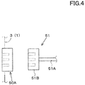
- the tractor (machine body 3) is provided with a first connector 50A for connecting to the in-vehicle network N1 from the outside, as shown in FIG. 3 and FIG. 4 .
- the first connector 50A is provided at the rear portion of the machine body 3.
- the first connector 50A is mounted at the rear of the lower portion of the cabin 9, for example, around a fender covering the upper portion of the rear wheels 7R.
- a communication cable 51 is connectable to the first connector 50A, which can be connected to the working device 2.
- the communication cable 51 includes a cable 51A and a second connector 51B attached to the end portion of the cable 51A and capable of connecting to the first connector 50A.
- a communication cable 51 can be connected to the first connector 50A.
- the tractor (machine body 3) and the working device 2 can communicate with each other.
- the shapes of the first connector 50A and the second connector 50B are not limited, and the first connector 50A side may have a male pin and the second connector 50B may have a female pin, the first connector 50A side may have a female pin and the second connector 50B may have a male pin, or any structure that allows the communication cable 51 to be connected to the first connector 50A via the second connector 50B.
- the tractor 1 is provided with an update controller device 53A.
- the update controller device 53A is a device that controls the updating of the update program of the working device 2, such as rewriting the update program to the working device 2.
- the update controller device 53A is connected to the in-vehicle network N1.
- the update controller device 53A has a non-volatile storage device 54.
- the update program is a program necessary to operate the working device 2 and is a program stored in the storage device 2c of the working controller device 2a of the working device 2.
- the update program is, for example, a control program relating to the operation of the working device 2, a display program relating to the display, a communication program relating to the communication, and the like.
- the type of the update program is not limited.
- the storage device 2c stores the identification information (type, model, model number, serial number, and the like) of the working device 2.
- the update controller device 53A causes the update controller device 54 to store the update program received by the communicator device 46 in the storage device 54.
- the update controller device 53A transmits the update program stored by the storage device 54 to the in-vehicle network N1 when the reception of the update program by the communicator device 46 is completed and the storage of the update program received by the communicator device 46 is completed in the storage device 54.
- the communicator device 46 completes receiving the update program and storing the update program received by the communicator device 46 in the storage device 54, when the communication cable 51 of the working device 2 is not connected to the first connector 50A, the update program is not transmitted to the in-vehicle network N1.
- the determination of whether or not the communication cable 51 of the working device 2 is connected to the first connector 50A for example, when a signal of a connection is sent from the update controller device 53A to the working device 2 and the update controller device 53A receives a signal from the working device 2 responding to the signal of the connection, it is determined that the first connector 50A is connected to the the communication cable 51 of working device 2 is connected.
- the update controller 53A cannot receive a signal from the working device 2 responding to the signal of the connection, it is determined that the communication cable 51 of the working device 2 is not connected to the first connector 50A.
- the update controller device 53A determines whether the communication cable 51 is connected or not by making a communication connection. Whether or not the communication cable 51 is connected to the first connector 50A is not limited to the method described above.
- the update controller device 53A determines that the communication cable 51 is connected to the first connector 50A, the update controller device 53A transmits an update signal to the notifier device 55 indicating that an update program has been sent to the in-vehicle network N1 (notifying that the update program is being sent) by the update controller device 53A.
- the notifier device 55 is, for example, a lamp that turns on or flashes a direction indicator 55a, a work light 55b, and the like, installed at the rear portion of the machine body 3.
- the direction indicator 55a When the direction indicator 55a receives an update signal, the direction indicator 55a reports that the update program is in the process of being updated by repeatedly blinking. Or, when the work light 55b receives an update signal, the work light 55b also repeats blinking to inform the user that the update program is in the process of being updated.
- the notifier device 55 When the notifier device 55 completes the transmission of the update program to the in-vehicle network N1, it stops sending (outputting) the update signal.
- the direction indicator 55a stops blinking, that is, the direction indicator 55a turns off the light, thereby informing the driver that the update program has been updated.
- the work light 55b stops blinking (that is, turns off the light) to inform the user that the update program has been completed.
- both the direction indicator 55a and the work light 55b were flashing, but either one of the direction indicators 55a and the work light 55b may be flashing, or instead of flashing, the light may be turned on, and the method of turning on the light during transmission of the update program is not limited.
- the update program is being transmitted by a lamp (light), but the notifier device 55 may be a sound generator device (speaker) 55c that generates sound.
- the speaker 55c receives an update signal, the speaker 55c notifies that the update program is being updated by generating sound from the speaker 55c, and when the speaker 55c no longer receives the update signal, the speaker 55c notifies that the update program has been updated by stopping the generation of sound.
- the transmission of the update signal when the transmission of the update program to the in-vehicle network N1 is completed, the transmission of the update signal is stopped; however, the transmission of the update signal may be stopped when the update controller device 53A receives from the working device 2 that the rewriting of the update program is completed.
- the update controller device 53A detects that the communication cable 51 has been removed from the first connector 50A (detection of removing during transmission of the update program to the in-vehicle network N1)
- the update controller device 53A transmits a warning signal to the notifier device 55 (direction indicator 55a, work light 55b, speaker 55c).
- the notifier device 55 (direction indicator 55A, work light 55B, and speaker 55C) provides a notification different from the update signal when a warning signal is received.
- the update controller device 53A can be determined, for example, by referring to the terminal (port) of the first connector 50A as a removal detection, or by whether or not it can receive a connection notification from the working device 2 during transmission of the update program.
- the method for detection of removing is not limited to the methods described above.
- the interval between the flashing of the direction indicators 55a and the work light 55b is shorter than when an update signal is received.
- the interval between the flashing of one direction indicator 55a and the other direction indicator 55a shall be the same for the hazard flashing, while when a warning signal is received, the flashing of one direction indicator 55a and the other direction indicator 55a shall be the same for the blinking at different intervals.
- the interval between the flashing of one work light 55b and the other work light 55b shall be the same, but when a warning signal is received, the flashing of one work light 55b and the other work light 55b shall be differently spaced.
- the volume (volume) of the sound when a warning signal is received shall be louder than when an update signal is received.
- the transmission of the update signal when the transmission of the update program to the in-vehicle network N1 is completed, the transmission of the update signal is stopped, but the transmission of the update signal may be stopped when the update controller device 53A receives via the communicator device 46 that the rewriting of the update program has been completed from the working device 2.
- the mobile terminal 47a may also be used to notify the mobile terminal 47a that the update program is being updated.
- the update controller device 53A outputs an update signal to the communicator device 46.
- the communicator device 46 transmits the update signal to the mobile terminal 47a.
- the mobile terminal 47a receives the update signal, the mobile terminal 47a displays on a screen, such as an LCD, that the update program is being updated.
- the direction indicator 55a and the work light 55b are described as lamps, but the lamps are not limited and may be, for example, brake lamps that are lit when braking (braking) is performed.
- "direction indicator 55a" and "work light 55b” can be read as "brake lamp”.
- the update program was stored in the memory device 54 of the update controller device 53A, but the update controller device 53A may divide one update program and distribute one update program to a plurality of electrical components connected to the in-vehicle network N1, for example, the memory devices 43 of the plurality of controller devices 40.
- the update controller device 53A when the update controller device 53A receives the update program via the communicator device 46, the update controller device 53A causes data A of the update program to be stored in the storage device 43 of the speed-shifting controller device 40A, data B to be stored in the storage device 43 of the engine controller device 40B, data C to be stored in the storage device 43 of the PTO controller device 40C, and data D to be stored in the storage device 43 of the lifting controller device 40D, for example.
- the update controller device 53A When the update controller device 53A transmits the update program to the working device 2, the update controller device 53A outputs a command to transmit the update program to each of the speed-shifting controller device 40A, the engine controller device 40B, the PTO controller device 40C, and the lifting controller device 40D, and causes the respective engine controller device 40B, the PTO controller device 40C, and the lifting controller device 40D to transmit data A, data B, data C, and data D.
- the update controller device 53A may receive data A, data B, data C, and data D from the engine controller device 40B, the PTO controller device 40C, and the lifting controller device 40D, and transmit data A, data B, data C, and data D to the working device 2.
- the update controller device 53A had a plurality of controller devices 40 divide the update program and store the update program in the storage device 43
- the above example is an example, and in the tractor, the destination of the data to which the update program is distributed is not limited to any electrical component as long as the electrical component has the storage device 43.
- the working machines 1 includes the machine body 3 capable of connecting the working device 2, the in-vehicle network installed in the machine body 3, the machine body controller device 40 to control the machine body 3, the update controller device 53A to control the update program of the working device 2, the first connector 50A installed in the machine body 3 and connected to the in-vehicle network N1, the notifier device 55, which notifies when the update program is sent to the in-vehicle network N1 by the update controller device 53A with the communication cable 51 of the working device 2 connected to the connector 50A.
- the communication cable 51 of the working device 2 when the communication cable 51 of the working device 2 is connected to the first connector 50A, when an update program is being transmitted from the working machines 1 (machine body 3) side to the working device 2, the information is provided by the notifier device 55, so that the communication cable 51 can be prevented from being removed from the first connector 50A by the operator (operator) or others during the transmission of the update program.
- the operator can easily update the update program to the working machines connected to the machine body, as the notifier device 55 allows the operator (driver) to understand that the update program has been transmitted.
- the working machine 1 is provided with the communicator device 46 capable of receiving the update program from the outside, and the storage device 54 storing the update program of the working device 2, and the update controller 53A stores the update program received by the communicator device 46 in the storage device 54, and then transmits the update program stored in the storage device 54 to the in-vehicle network N1 after the receipt of the update program by the communicator device 46 is completed.
- the update program is output to the in-vehicle network N1 after the reception of the update program is securely completed in the communicator device 46, thus preventing errors in updating the update program due to the influence of the communication status.
- the working machines 1 has a plurality of electrical components connected to the in-vehicle network N1, and the update controller device 53 distributes the update program to the plurality of electric components. According to this configuration, even when the capacity (data capacity) of the update program is large, the update program can be stored (retained) in the plural electrical components.
- the notifier device 55 is a lamp installed in the machine body, and the lamp informs the operator (worker) that the update program is in the process of being updated. According to this configuration, the operator (worker) and others can reliably understand that the update program is being updated by the lighting or blinking of the lamp.
- the notifier device 55 is a speaker installed in the machine body 3, and reports that the update program is being updated by the sound output from the speaker. According to this configuration, the operator (worker) or others can reliably understand that the update program is being updated by the sound from the speaker.
- the notifier device 55 provides a different notification from the update when the communication cable 51 has been removed from the first connector 50A. According to this configuration, the operator (worker) can be informed that the communication cable 51 has been removed before the update of the update program has been completed.
- the update controller device 53A provides notification to the mobile terminal 47a. According to this configuration, the mobile terminal 47a, which is possessed by the operator (worker), is also informed, so that it can be more prevented from accidentally removing the communication cable 51 while updating the update program.
- FIG. 7 shows the control block of the working machines and the program update system of the working machines according to a second embodiment of the present invention.
- the drawing shows the control block of the working machines and the program update system of the working machines according to the second embodiment.
- the same configuration as those in the first embodiment is omitted from the description with the same reference numerals.
- the tractor 1 is provided with an update controller device 53B.
- the update controller device 53B like the update controller device 53A, controls the updating of the update program of the working device 2, such as rewriting the update program to the working device 2.
- the update controller device 53B is connected to the in-vehicle network N1.
- the update controller device 53B has a non-volatile storage device 54.
- the storage device 54 stores the update program sent by the external device 47 (mobile terminal 47A, stationary terminal 47B).
- the update controller device 53B executes the update program to the working device 2 according to the condition of the machine body 3 or the working device 2.
- FIG. 8 shows an example of a map that includes the parking area P1 and agricultural field H1.
- the parking area P1 is a place to store the tractor 1, working device 2, and the like, and in the case of agricultural machine, it is a farmer or the like, and in the case of construction machine, it is a construction company or a rental company that rents construction machine.
- the update controller device 53B executes the update of the update program when the tractor 1 with the working device 2 connected to the parking area P1 is stopped and the communication cable 51 of the working device 2 is connected to the first connector 50A when the update program is stored in the storage device 54.
- the update controller device 53B refers to the body position detected by the positioning device 41k when the communication cable 51 is connected to the first connector 50A.
- the update controller device 53B refers to the map data stored in the storage device 54 in advance. Alternatively, the update controller device 53B connects to the server of the map provider providing the map via the communicator device 46 to obtain the map data and determine whether the current body location is the parking area P1.
- the area information of the parking area P1 (latitude and longitude range indicating the parking area P1) is selected from the map data by operation of the mobile terminal 47a and stored in the storage device 54.
- the update controller 53B determines that the tractor 1 (machine body 3) is the parking area P1 when the current body position is within the latitude and longitude indicated in the area information of the parking area P1.
- the update controller 53B determines that the tractor 1 (machine body 3) is not the parking area P1 when the current body position is outside the range of latitude and longitude indicated in the area information of the parking area P1.
- the update controller device 53B executes the update program by sending the update program stored in the storage device 54 to the working device 2 via the in-vehicle network N1.
- the update controller device 53B may determine whether the tractor 1 (machine body 3) to which the working device 2 is connected is in transportation or not based on the body position, and when the tractor 1 is in transportation, the update program update may be executed.
- the tractor (machine body 3) and the working device 2 are loaded into a transport vehicle 17, such as a truck, with the tractor (machine body 3) and the working device 2 connected to the tractor (machine body 3) and the working device 2 at the parking area P1.
- the transporter vehicle 17 is driven by a driver (operator) and transported to the agricultural field HI.
- the update controller device 53B obtains from the speed-shifting controller device 40A, the engine controller device 40B, the PTO controller device 40C, and the like, that the driving portions of the tractor (the prime mover 4, the PTO shaft 16, the speed-shifter device 5) have stopped, while referring to the body position detected by the positioning device 41k.
- the update controller device 53B determines that the machine body 3 (working device 2) is in transportation, and transmits the update program stored in the storage device 54 to the working device 2 via the in-vehicle network N1 to execute the update program.
- the update controller device 53B determines that the machine body 3 (working device 2) is not in transportation and does not execute the update program.
- the update program was performed when the tractor 1 (machine body 3) is stopped at the parking area P1 and the tractor 1 (machine body 3) and the working device 2 are in transportation, but the update controller device 53B may perform the update program update when the power transmission portion (speed-shifter device 5) is not transmitting power to the working device 2.
- the tractor 1 is provided with a PTO switch 61 that switches the PTO clutch 5e1 to an engaged and disengaged state.
- the PTO switch 61 is, for example, a switch that can be switched ON/OFF, and when the PTO switch 61 is ON, the PTO controller device 40C outputs a control signal to the PTO control valve 62, which is engaged to the PTO clutch 5e1 by a fluid line, to bring the PTO clutch 5e1 into the engaged state.
- the PTO controller device 40C When the PTO switch 61 is off, the PTO controller device 40C outputs a control signal to the PTO control valve 62, which is engaged to the PTO clutch 5e1 by an fluid line, to put the PTO clutch 5e1 in the disengaged state.
- the update controller device 53B determines that the power is not being transmitted to the working device 2, and transmits the update program stored in the storage device 54 to the working device 2 via the in-vehicle network N1.
- the update controller device 53B prohibits the PTO control by the PTO controller 40C while the update program is being transmitted (while the update program is being updated). That is, while the update controller device 53B is transmitting the update program to the working device 2 (updating the update program), the PTO controller device 40C does not output a control signal to the PTO control valve 62 to put the PTO clutch 5e1 in the connected state, even when the PTO switch 61 is turned ON, and maintains the PTO clutch 5el in the disengaged state.
- the update controller device 53B After the update controller device 53B transmits the update program to the working device 2, when the update controller device 53B receives a notification from the working device 2 that the update of the update program is complete, the update controller device 53B releases the prohibition of the PTO control.
- the PTO control is described as an example, but it is not limited to this.
- the update controller device 53B outputs a command to set the PTO clutch 5e1 of the power transmission portion (speed-shifter device 5) to the PTO controller device 40C to disengage the PTO clutch 5e1 (stop command) when the PTO clutch 5e1 of the power transmission portion (speed-shifter device 5) is in a engaged state before the transmission of the update program (update of the update program) is performed.
- the PTO controller device 40C When the PTO controller device 40C receives a stop command from the update controller device 53B, the PTO controller 40C outputs a control signal to the PTO control valve 62 that sets the PTO clutch 5e1 to the disengaged state, and holds the PTO clutch 5el in the disengaged state. Thereafter, the update controller device 53B executes the update program by sending the update program stored in the storage device 54 to the working device 2 via the in-vehicle network N1.
- the update controller device 53B executes the update program update after stopping the transmission of power to the working device 2.
- the update controller device 53B prohibits the PTO control by the PTO controller device 40C during the transmission of the update program (while the update program is being updated).
- the PTO control is described as an example, but it is not limited to this.
- the update controller device 53B prohibits the control of the power transmission portion (hydraulic control valve 27) by the auxiliary hydraulic controller device 40G when the update program is transmitted (updating the update program). That is, it is prohibited to output a control signal to operate the hydraulic control valve 27, even when the hydraulic operation tool 42J is operated.
- the update controller device 53B lifts the prohibition of control by the assist hydraulic controller device 40G when the update program is completed.
- the update program can be executed in the same manner as the PTO controller device 40C, with no power transmitted to the working device 2.
- the transmission of the update program in the update controller device 53B (during the execution of the update of the update program) indicates on the mobile terminal 27a and the display device 45 that the update program is being updated and that the working device 2 cannot be operated while the update program is being updated.
- the update controller device 53B may execute the update program update when the lifting and lowering device 8 has not raised the working device 2.
- the update controller device 53B outputs a lowering command to lower the lifter device 8 (the working device 2) to the lifting controller device 40D before sending the update program (updating the update program).
- the lifting controller device 40D When the lifting controller device 40D receives a command to descend, the lifting controller device 40D contracts the lift cylinder 8e by controlling the control valve 34 to lower the rear end of the lift arm 8a (the end portion of the working device 2 side).
- the update controller device 53B prohibits the lifting and lowering control by the lifting controller device 40D after the lowering of the lifter device 8.
- the lifting controller device 40D prohibits the lifting controller device 40D from outputting a control signal to raise and lower the control valve 34, even when the one-touch switch 42g and the height setting dial 42h are operated.
- the update controller device 53B lifts the prohibition on the elevation control when the update program is completed.
- the tractor is provided with a timer portion 65, which counts the time.
- the timer portion 65 counts the month, day, and time (hours and minutes) as the time.
- the update controller 53B refers to the time timed by the timer portion 65 with the working device 2 connected to the tractor.
- the identification information of the working device 2 is obtained from the storage device 2c of the working device 2.
- the update controller 53B transmits identifying information to the server 47B via the communicator device 46, and obtains from the server 47B the agricultural operations (tilling, plowing, rowing, rice planting, harvesting, sowing, fertilizing, pest control, mowing, rowing, and transplanting) that can be performed by the working device 2.
- the update controller device 53B obtains the agricultural tasks that can be performed by the working device 2 and executes an update of the update program when the time counted by the timer portion 65 is a time when the agricultural tasks are not performed.
- the update program is updated because it is the time when scraping is not performed.
- the program update system of the working machines 1 is a program update system of the working machines 1 including the machine body 3, the working device 2 provided on the machine body 3 to perform work, the storage device 54 storing updates of the update program of the machine body 3 or the working device 2, and the update controller 53B controlling the update of the update program, wherein the update controller 53B executes the update of the update program to the working device 2 according to the condition of the machine body 3 or the working device 2.
- the program update system of the working machine 1 is provided with the positioning device 41K that detects the position of the machine body 3, and the update controller 53B executes the update program update when the position detected by the positioning device 41K is the parking area of the machine body 3.
- the update controller 53B determines whether or not the machine body 3 is in transportation based on its position, and when it is in transportation, the update controller 53B executes an update of the update program.
- the update program can be reliably updated when the working machines 1 is in transportation and the working machines 1 is not being used for work, and the update program can be updated smoothly.
- the machine body 3 has a power transmission portion (speed-shifter device 5, hydraulic control valve 27) that transmits power to the working device 2, and the update controller device 53B executes the update program update when the power transmission portion (speed-shifter device 5, hydraulic control valve 27) is not transmitting power to the working device 2.
- the machine body 3 has a power transmission portion (speed-shifter device 5, hydraulic control valve 27) that transmits power to the working device 2, and the update controller device 53B executes updating of the update program after stopping the transmission of power to the working device 2 by the power transmission portion (speed-shifter device 5, hydraulic control valve 27).
- the machine body 3 has a lifter device 8 that raises and lowers the working device 2, and the update controller 53B executes an update of the update program when the lifter device 8 has not raised the working device 2.
- the update program can be updated when the working device 2 is not raised, that is, when the working device 2 is lowered.
- the program update system for the working machines 1 is provided with the timer portion 65 that counts the time, and the update controller device 53B determines whether or not it is time for the working device 2 to be out of use based on the timer portion 65 and the identification information of the working device 2, and executes an update of the update program when the working device 2 is not in use.
- the latest program can be stored in the working device 2 before the work is done because the updated program can be updated at a time when the working device 2 is not used, that is, before the working device 2 is used.
- the working device 2 when applied to other working machines 1, for example, construction machine, the working device 2 is a bucket, a hydraulic crusher, a hydraulic breaker, an angle broom, an earth auger, a pallet fork, a sweeper, a mower, a snow blower, and the like, which can be applied to update the update program of the working device 2.
- the update controller device 53B may update the update program of the working device 2 when the DPF is regenerated, since it is necessary to stop the machine body 3 (working device 2) when the DPF is regenerated.
- DPF diesel particulate filter
- the communicator device 46 of the working machines 1, such as the tractor receives (acquires) the update program transmitted in wireless from the external device 47 (mobile terminal 47a, stationary terminal 47b), but the working machines 1 may not only acquire the update program by radio, but also acquire the update program in wired.
- the working machine 1 has a connector interface for connecting electronic storage media such as a USB memory, SD card, and the like, a computer (personal computer, laptop), and a portable device 47a (a device having a memory), and the update program may be obtained via the connector interface.
- electronic storage media such as a USB memory, SD card, and the like
- a computer personal computer, laptop
- portable device 47a a device having a memory
Landscapes
- Engineering & Computer Science (AREA)
- General Engineering & Computer Science (AREA)
- Software Systems (AREA)
- Theoretical Computer Science (AREA)
- Computer Security & Cryptography (AREA)
- Physics & Mathematics (AREA)
- General Physics & Mathematics (AREA)
- Civil Engineering (AREA)
- Structural Engineering (AREA)
- Mining & Mineral Resources (AREA)
- Mechanical Engineering (AREA)
- Lifting Devices For Agricultural Implements (AREA)
- Stored Programmes (AREA)
Abstract
Description
- The present invention relates to a working machine and to a program update system for the working machine such as an agriculture machine and a construction machine.
-
Patent Document 1 is known as a system for writing an update program of a working machine. - In a program updating method for a controller device of a working machine configured to write the update program to the controller device of the working machine connected to a vehicle communication network of
Patent Document 1, the program updating method includes steps of preliminarily setting data for checking a computer program of the controller device for the working machine, erasing data to be used to check an existing computer program preliminarily stored in the controller device before the update program is written to the controller device for the working machine, and then writing the update program to the controller device for the working machine and writing data to be used to check the update program lastly to the controller device for the working machine. - [Patent Document 1] Japanese Unexamined Patent Publication No.
2010-176372 -
Patent Document 1 is very useful because it allows an update program to be properly written to a controller device installed in a working machine. However,Patent Document 1 does not consider updating the update program of the working machine, that is, another working device connected to the vehicle body. - In view of the above-mentioned problems, the present invention intends to provide a communication system for a working machine capable of easily updating an update program of a working device connected to the machine body.
- Technical means of the present invention for solving this technical problem is characterized by the following points.
- A program update system for a working machine, includes: a machine body; a working device to be used for work, the working device being provided to the machine body; a storage device to store an update program for the machine body or the working device; and an update controller to control the update program. The update controller executes the update program for the working device based on a state of the machine body or the working device.
- The program update system for the working machine mentioned above, includes a positioning device to detect a position of the machine body. The update controller executes the update program when the position detected by the positioning device is a parking area of the machine body.
- The update controller judges whether the machine body is in being transported based on the position, and executes the update program when the machine body is in being transported.
- The machine body includes a power transmission device to transmit power to the working device, and the update controller executes the update program when the power transmission device is free from transmitting power to the working device.
- The machine body includes a power transmission device to transmit power to the working device, and the update controller executes the update program after the power transmission device stops transmitting power to the working device.
- The machine body includes a lifter device to lift the working device, and the update controller executes the update program when the lifter device is free from lifting the working device.
- The program update system for the working machine mentioned above, includes a timer to count time. The update controller judges whether the working device is in a period free from being used based on the time counted by the timer and identification information of the working device, and executes the update program in the period free from being used.
- A working machine includes: a machine body to be connected to a working machine; an in-vehicle network provided to the machine body; a machine body controller to control the machine body; an update controller to control an update program of the working device; a first connector to be connected to the in-vehicle network, the first connector being provided to the machine body; and a notifier to issue notification when the update controller transmits the update program to the in-vehicle network under a state where a communication cable of the working device is connected to the first connector.
- The working machine mentioned above, includes: a communicator to receive the update program from outside; and a storage device to store the update program for the working device. The update controller stores the update program received by the communicator to the storage device, and then transmits the update program stored in the storage device to the in-vehicle network after the communicator completes receiving the update program.
- The working machine mentioned above, includes a plurality of electric components connected to the in-vehicle network. The update controller distributes the update program to the plurality of electric components.
- The notifier is a lamp provided to the machine body and configured to be lighted to issue notification that represents the update program is in being executed.
- The notifier is a speaker provided to the machine body and configured to output sounds to issue notification that represents the update program is in being executed.
- The notifier issues notification representing other than the execution of the update program when the communication cable is disconnected from the first connector.
- The update controller issues the notification to a mobile terminal.
- According to the present invention. it is possible to easily update update program of a working machine connected to a machine body.
-
-
FIG. 1 is a configuration view of a speed-shifter device according to an embodiment of the present invention. -
FIG. 2 is a perspective view of a lifter device according to an embodiment of the present invention. -
FIG. 3 is a view illustrating a control block of a working machine and a program update system for a working device according to a first embodiment of the present invention. -
FIG. 4 is a view illustrating a first connector and a communication cable according to an embodiment of the present invention. -
FIG. 5 is a view illustrating a relation between transmission of an update program (updating) and an operation of a notifier device according to an embodiment of the present invention. -
FIG. 6 is an explanation view of dividing an update program into a plurality of controller devices according to an embodiment of the present invention. -
FIG. 7 is a view illustrating a control block of a working machine and a program update system for a working device according to a second embodiment of the present invention. -
FIG. 8 is a view illustrating an example of a map including a parking area P1 and an agricultural field H1 according to an embodiment of the present invention. -
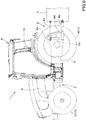
FIG. 9 is a whole view of a tractor according to an embodiment of the present invention. - Hereinafter, an embodiment of the present invention will be described with appropriate reference to the drawings.
-
FIG. 3 shows a control block ofworking machine 1 and a communication system ofworking machine 1. The workingmachine 1 is an agricultural machine such as a tractor, a combine, a rice planter, and the like, and a construction machine such as a loader and a backhoe. - The working machine will be described below, taking the tractor as an example. As described above, the
working machine 1 is not limited to the tractor, and therefore, the configuration common to agricultural machinery such as a combine, a rice planter, and the like, and a construction machine such as a loader and a backhoe can be replaced. That is, the description of the tractor can be read as other agricultural and construction machinery. - As shown in
FIG. 9 , the tractor is provided with amachine body 3 having atraveling device 7, aprime mover 4, and a speed-shifter device 5. Thetraveling device 7 is a device having afront wheel 7F and arear wheel 7R. Thefront wheels 7F may be of the tire or crawler type. - The
rear wheels 7R may also be of the tire or crawler type. Theprime mover 4 is a gasoline engine, an internal combustion engine such as a diesel engine, an electric motor, and the like. In this embodiment, theprime mover 4 is a diesel engine. - The speed-
shifter device 5 is capable of switching the propulsion of thetraveling device 7 by shifting gears and of switching thetraveling device 7 forward or backward. Acabin 9 is provided in themachine body 3, and anoperator seat 10 is provided in thecabin 9. - A
coupler portion 8 is provided at the rear portion of themachine body 3. Thecoupler portion 8 is detachable with theworking device 2. In this embodiment, thecoupler portion 8 is a lifter device that raises and lowers the attachedworking device 2. - The
working device 2 includes a cultivating device for cultivating, a fertilizer sprayer device for spraying fertilizer, a pesticide sprayer device for spraying pesticides, a harvester device for harvesting, a mower device for harvesting pastures and the like, a tedder device for diffusing pastures and the like, a grass rake for collecting pastures and the like, a baler device for molding pastures and the like. - As shown in
FIG. 3 , the workingdevice 2 is provided with a work controller device (controller device) 2a. Thework controller device 2a is a device for various controls of the workingdevice 2, and includes a CPU, electrical and electronic circuits, and the like. - The
work controller device 2a has a storage device 2b for storing various information, for example, a control program, identification information, and the like. The storage device 2b includes a non-volatile memory or the like. - As shown in
FIG. 1 , the speed-shifter device 5 includes a main shaft (propulsion shaft) 5a, ashuttle portion 5b, a main speed-shifter portion 5c, a sub speed-shifter portion 5d, a PTO power speed-shifter portion 5e, and a front speed-shifter portion 5f. - The
propulsion shaft 5a is rotatably supported in the housing case of the speed-shifter device 5, and power from the crankshaft of theprime mover 4 is transmitted to thepropulsion shaft 5a. - The
shuttle portion 5b has a shuttle shaft 5b1 and a forward/backward switching portion 5b2. The power from thepropulsion shaft 5a is transmitted to the shuttle shaft 5b1. The forward/backward switching portion 5b2 includes, for example, a hydraulic clutch or the like, and switches the direction of rotation of the shuttle shaft 5b1, that is, forward and backward movement of the tractor, by turning the hydraulic clutch on and off. - The main speed-
shifter portion 5c is a stepless transmission mechanism that changes the input power to stepless. The stepless transmission mechanism has a hydraulic pump 5c1, a hydraulic motor 5c2, and a planetary gear mechanism 5c3. - The hydraulic pump 5c1 is rotated by power from the output shaft 5b3 of the
shuttle portion 5b. The hydraulic pump 5c1 is, for example, a variable displacement pump having aswash plate 12, and by changing the angle of the swash plate 12 (a swash plate angle), the flow rate of hydraulic fluid output from the hydraulic pump 5c1 can be changed. - The hydraulic motor 5c2 is a motor that is rotated by the hydraulic fluid output from the hydraulic pump 5c1 through a piping or other fluid circuit. The number of revolutions of the hydraulic motor 5c2 can be changed by changing the swash plate angle of the hydraulic pump 5c1 or by changing the power input to the hydraulic pump 5c1.
- The planetary gear mechanism 5c3 is a mechanism including a plurality of gears (gears) and a power transmission shaft such as an input shaft and an output shaft, and includes an
input shaft 13, wherein the power of the hydraulic pump 5c1 is input, aninput shaft 14, wherein the power of the hydraulic motor 5c2 is input, and anoutput shaft 15, wherein the power is output. - The planetary gear mechanism 5c3 combines the power of the hydraulic pump 5c1 and the power of the hydraulic motor 5c2 and transmits the combined power to the
output shaft 15. - Accordingly, according to the main speed-
shifter portion 5c, the power output to the sub speed-shifter portion 5d can be changed by changing the swash plate angle of theswash plate 12 of the hydraulic pump 5c1, the number of revolutions of theprime mover 4, and the like, according to the main speed-shifter portion 5c. Although the main speed-shifter portion 5c includes a stepless transmission mechanism, the main speed-shifter portion 5c may be a stepless transmission mechanism in which gears are used to change the speed. - The sub speed-
shifter portion 5d is a transmission mechanism having a plurality of stepped gears (gears) for changing the power, and by changing the connection (engagement) of the plurality of gears accordingly, the power input to the sub speed-shifter portion 5d from theoutput shaft 15 of the planetary gear mechanism 5c3 is changed and output (shifting). The sub speed-shifter portion 5d includes an input shaft 5d1, a first speed-shifter clutch 5d2, a second speed-shifter clutch 5d3, and an output shaft 5d4. - The input shaft 5d1 is a shaft to which the power of the
output shaft 15 of the planetary gear mechanism 5c3 is input, and inputs the input power to the first speed-shifter clutch 5d2 and the second speed-shifter clutch 5d3 via gears and the like. By switching the connection and disconnection of the first speed-shifter clutch 5d2 and the second speed-shifter clutch 5d3, the input power is changed and output to the output shaft 5d4. - The power output to the output shaft 5d4 is transmitted to the rear wheel
differential device 20R. The rear wheeldifferential device 20R rotatably supports therear axle 21R on which therear wheels 7R are mounted. - The PTO power speed-
shifter device 5e has a PTO clutch 5el, a PTO propulsion shaft 5e2, and a PTO speed-shifter device 5e3. For example, the PTO clutch 5e1 is constituted of a hydraulic clutch or the like, and is configured to switch by turning the hydraulic clutch on and off between a state where the power of thepropulsion shaft 5a is transmitted to the PTO propulsion shaft 5e2 (an engaged state) and a state where the power of thepropulsion shaft 5a is not transmitted to the PTO propulsion shaft 5e2 (a disengaged state). - The PTO speed-shifter portion 5e3 includes a speed-shifter clutch and a plurality of gears, and outputs the power (speed) input from the PTO propulsion shaft 5e2 to the PTO speed-shifter portion 5e3 by changing the power (speed).
- The front speed-
shifter portion 5f has a first front speed-shifter clutch 5fl and a second front speed-shifter clutch 5f2. The first and second front speed-shifter clutches 5f1 and 5f2 are capable of transmitting power from the sub-speed speed-shifter portion 5d, for example, the power of the output shaft 5d4 is transmitted via the gear and the transmission shaft. - The power from the first and second front speed-shifter clutches 5f1 and 5f2 can be transmitted to the
front axle 21F via thefront transmission shaft 22. In particular, thefront transmission shaft 22 is connected to the front wheeldifferential device 20F, and the front wheeldifferential device 20F rotatably supports thefront axle 21F to which thefront wheels 7F are attached. - The first front speed-shifter clutch 5f1 and the second front speed-shifter clutch 5f2 include a hydraulic clutch or the like. A fluid line is connected to the first front speed-shifter clutch 5f1, and the fluid line is connected to a
control valve 23 to which hydraulic fluid output from the hydraulic pump is supplied. The first front speed-shifter clutch 5f1 is switched between an engaged state and a disengaged state according to the degree of opening of thecontrol valve 23. - A fluid line is connected to the second front speed-shifter clutch 5f2, and the fluid line is connected to the
control valve 24. The second front speed-shifter clutch 5f2 is switched between to an engaged state and a disengaged state by opening thecontrol valve 24. Thecontrol valve 23 and thecontrol valve 24 are, for example, a two-position switching valve with a solenoid valve, which is switched between the engaged state and the disengaged state by magnetization or demagnetization of the solenoid valve. - When the first front speed-shifter clutch 5f1 is disengaged and the second front speed-shifter clutch 5f2 is engaged, the power of the sub speed-
shifter portion 5d is transmitted to thefront wheels 7F through the second front speed-shifter clutch 5f2. This results in four-wheel drive (4WD) in which the front and rear wheels are driven by the power, and in which the rotation speeds of the front and rear wheels are approximately the same (4WD constant speed state). - On the other hand, when the first front speed-shifter clutch 5f1 is engaged and the second front speed-shifter clutch 5f2 is disengaged, four-wheel drive is provided and the rotation speed of the front wheels becomes higher than that of the rear wheels (4WD double speed state). When the first and second front speed-shifter clutches 5f1 and 5f2 are engaged, the power of the sub speed-
shifter portion 5d is not transmitted to thefront wheels 7F, and thus the rear wheels are driven by power in a two-wheel drive (2WD) system. - As shown in
FIG. 2 , the lifter device (coupler portion) 8 has alift arm 8a, alower link 8b, atop link 8c, alift rod 8d, and alift cylinder 8e. The front end portion of thelift arm 8a is pivotally supported upwardly or downwardly in the upper rear portion of the case (transmission case) housing the speed-shifter device 5. Thelift arm 8a is pivoted (raised or lowered) by the actuation of thelift cylinder 8e. - The
lift cylinder 8e includes a hydraulic cylinder. Thelift cylinder 8e is connected to a hydraulic pump via a control valve 34. The control valve 34 is a solenoid valve or the like, which stretches and shortens thelift cylinder 8e. - The front end portion of the
lower link 8b is pivotally supported upwardly or downwardly in the rear lower portion of the speed-shifter device 5. The front end portion of thetop link 8c is pivotally supported upwardly or downwardly on the rear portion of the speed-shifter device 5 above thelower link 8b. - A
lift rod 8d connects thelift arm 8a to thelower link 8b. A workingdevice 2 is connected to the rear portion of thelower link 8b and the rear portion of thetop link 8c. When thelift cylinder 8e is activated (telescoping), thelift arm 8a is raised and lowered, and thelower link 8b connected to thelift arm 8a via thelift rod 8d is raised and lowered. - This allows the working
device 2 to pivot (raise or lower) upward or downward with the front portion of thelower link 8b as the fulcrum. - A
posture changer device 25 is provided in thelifter device 8. Theposture changer device 25 is a device for changing the posture of the workingdevice 2 mounted on themachine body 3. Theposture changer device 25 has achanger cylinder 25a including a hydraulic cylinder and acontrol valve 25b. - The
changer cylinder 25a is connected to the hydraulic pump via acontrol valve 25b. Thecontrol valve 25b is a solenoid valve or the like to extend and retract thechanger cylinder 25a. Thechanger cylinder 25a connects thelift arm 8a to thelower link 8b. - As shown in
FIG. 3 , the tractor has a plurality ofhydraulic control valves 27. The plurality ofhydraulic control valves 27 are hydraulic switching valves to which hydraulic fluid is supplied from thehydraulic pump 28. The plurality ofhydraulic control valves 27 each have output ports, and a hydraulic hose or the like can be connected to any of the output ports. - The hydraulic hoses connected to any of the output ports of the
hydraulic control valves 27 can be connected to the hydraulic attachments of the workingdevice 2 to operate the various hydraulic attachments attached to the workingdevice 2. - The
steering device 11 has a steering wheel (steering wheel) 11a, a rotating shaft (steering axis) 11b that rotates with the rotation of thesteering wheel 11a, and an assist mechanism (power steering mechanism) 11c that assists the steering of thesteering wheel 11a. - The
assist mechanism 11c includes acontrol valve 35 and asteering cylinder 32. Thecontrol valve 35 is, for example, a three-position switching valve that can be switched by movement of a spool or the like. Thecontrol valve 35 can also be switched by steering the steering shaft 11B. Thesteering cylinder 32 is connected to an arm (knuckle arm) 36, which changes the direction of thefront wheels 7F. - Accordingly, by operating the
handle 11a, the switching position and opening degree of thecontrol valve 35 is switched according to thehandle 11a, and the steering direction of thefront wheels 7F can be changed by telescoping thesteering cylinder 32 to the left or right according to the switching position and opening degree of thecontrol valve 35. Thesteering device 11 described above is an example and is not limited to the configuration described above. - As shown in
FIG. 3 , the tractor is provided with a plurality ofdetector devices 41. The plurality ofdetector devices 41 are devices for detecting a condition of the tractor. The plurality ofdetector devices 41 include, for example, awater temperature sensor 41a for detecting the water temperature, a fuel sensor 41b for detecting the remaining amount of fuel, a prime mover revolutions sensor (rotation sensor) 41c for detecting the number of revolutions of theprime mover 4, an accelerator pedal sensor 41d for detecting the amount of operation of the accelerator pedal, a steering angle sensor 41 e for detecting the steering angle of thesteering device 11, an angle sensor 41f for detecting the angle of thelift arm 8a, a tilt detector sensor 41g for detecting the tilt of themachine body 3 in the width direction (right or left), a speed sensor 41h for detecting the speed of themachine body 3, a PTO rotation sensor (rotation sensor) 41i for detecting the number of rotations of the PTO axis, a battery sensor 41j for detecting the voltage of the storage batteries of the machine body, a positioning sensor (positioning device) 41k for detecting the position of themachine body 3 based on signals from positioning satellites and the like. - The
positioning device 41k is capable of detecting its own position (positioning information including latitude and longitude) by a satellite positioning system (positioning satellites) such as D-GPS, GPS, GLONASS, HOKUTO, GALILEO, and MICHIBIKI. - That is, the
positioning device 41k receives a satellite signal transmitted from the positioning satellite (position of the positioning satellite, transmission time, correction information, and the like) and detects the position (for example, latitude and longitude) of thetractor 1, that is, the body position, based on the satellite signal. - The
positioning device 41k has a receiver device and an Inertial Measurement Unit (IMU). The receiver device is a device having an antenna or the like to receive satellite signals transmitted from a positioning satellite and is attached to themachine body 3 separately from the inertial measurement device. - In this embodiment, the receiver device is attached to the
machine body 3. The attachment point of the receiver device is not limited to the embodiment. - The inertial measurement device has an acceleration sensor to detect acceleration, a gyro sensor to detect angular velocity, and the like. The
machine body 3, for example, is installed below theoperator seat 10, and the roll angle, pitch angle, yaw angle, and the like of themachine body 3 can be detected by the inertial measurement device. - The speed sensor 41h detects the vehicle speed by converting, for example, the number of rotations of the
front axle 21F, the number of rotations of therear axle 21R, the number of rotations of thefront wheels 7F, the number of rotations of therear wheels 7R, and the like into vehicle speed. The speed sensor 41h can also detect the directions of rotations of thefront axle 21F, therear axle 21R, thefront wheels 7F and therear wheels 7R, and can also detect whether the tractor (machine body 3) is moving forward or backward. Thedetector device 41 described above is an example and is not limited to the sensors described above. - The tractor is also provided with a plurality of operating members (controller devices) 42. The plurality of
operation members 42 include ashuttle lever 42a for switching the forward or backward movement of themachine body 3, an ignition switch 42b for starting theprime mover 4 and the like, a PTO speed-shifter lever 42c for setting the number of revolutions of the PTO shaft, a speed-shifter change switch 42d for switching between automatic speed-shifting and manual speed-shifting, a speed-shifter lever 42e to manually switch speed-shifting steps (speed-shifting level) of the speed-shifter device 5, the accelerator 42f to accelerate or decelerate the vehicle speed, a one-touch switch 42g to raise or lower thelifter device 8, a height setting dial 42h for setting the upper limit of thelifter device 8, a vehicle speed lever 42i for setting the vehicle speed, a hydraulic operation tool 42j, arevolutions setting tool 42k for setting the upper limit of the revolutions speed of the prime mover, and the like. - The setting tools, such as the speed-shifter change switch 42d, the height setting dial 42h, and the
revolutions setting tool 42k are provided in a console box on the side of theoperator seat 10. The operation of themachine body 3 can be set by the operator by operating the setting tools (the speed-shifter change switch 42d, the height setting dial 42h, and therevolutions setting tool 42k). Theoperation members 42 described above are an example and are not limited to those described above. - As shown in
FIG. 3 , the tractor has a plurality of machinebody controller devices 40. The machinebody controller device 40 is a device that performs various controls of the tractor (machine body 3) and includes a CPU, electrical and electronic circuits, or the like. - The machine
body controller device 40 has astorage device 43 that stores various information, for example, a control program, identification information, and the like. Thestorage device 43 includes a non-volatile memory or the like. That is, the plurality of machinebody controller devices 40 are electrical components provided with thestorage device 43. - The plurality of machine
body controller devices 40 include a speed-shiftingcontroller device 40A, anengine controller device 40B, aPTO controller device 40C, an liftingcontroller device 40D, an automaticsteering controller device 40E, anposture controller device 40F, and an assisthydraulic controller device 40G. - The
controller device 40 need not include all of the speed-shiftingcontroller device 40A, theengine controller device 40B, thePTO controller device 40C, the liftingcontroller device 40D, the automaticsteering controller device 40E, theposture controller device 40F, and the assisthydraulic controller device 40G, and may be provided according to the specifications of the tractor. - The speed-shifting
controller device 40A, theengine controller device 40B, thePTO controller device 40C, the liftingcontroller device 40D, the automaticsteering controller device 40E, theposture controller device 40F and the assisthydraulic controller device 40G may be provided in an integrated controller device. - The speed-shifting
controller device 40A executes the speed shifting control. In the speed shifting control, when the automatic speed shifting function is enabled, one of the main speed-shifter portion 5c and the sub speed-shifter portion 5d are automatically switched according to the condition of the tractor, and the speed shifting step (speed shifting level) of the speed-shifter device 5 is automatically changed to a predetermined speed shifting stage (speed shifting level). - In the speed shifting control, when the speed-shifter change switch 42d is switched to the manual speed shifting, one of the main speed-
shifter portion 5c and one of the sub speed-shifter portion 5d is automatically switched according to the speed shifting level (speed shifting level) set by the speed-shifter lever 42e, to change the speed shifting step of the speed-shifter device 5. - The speed shifting
controller device 40A performs control (traveling switching control) of the traveling drive state (operation of the traveling device 7) of the travelingdevice 7. In the traveling switching control, when theshuttle lever 42a is operated in the forward direction, the forward/backward switching portion 5b2 of theshuttle portion 5b is switched to forward, thereby advancing themachine body 3. - The traveling switching control causes the
machine body 3 to move backward by switching the forward/backward switching portion 5b2 of theshuttle portion 5b to backward when theshuttle lever 42a is operated to backward. - In the traveling switching control, in the case of 4WD, the first front speed-shifter clutch 5f1 is disconnected and the second front speed-shifter clutch 5f2 is connected. In the traveling switching control, in case of 4WD double speed, the first front speed-shifter clutch 5fl shall be connected and the second front speed-shifter clutch 5f2 shall be disengaged. In the traveling switching control, in case of 2-wheel drive, the first front speed-shifter clutch 5fl and the second front speed-shifter clutch 5f2 are engaged.
- The
engine controller device 40B executes the engine control. In the engine control, when the ignition switch 42b is operated to ON, theprime mover 4 is started after a predetermined process, and when the ignition switch 42b is operated to OFF, the driving of theprime mover 4 is stopped. - In the engine control, when the accelerator 42f is operated, the vehicle speed (velocity) of the
machine body 3 is changed by changing the number of revolutions of the prime mover 4 (referred to as the prime mover speed) according to the amount of operation of the accelerator 42f. - The
PTO controller device 40C performs the PTO control, in which the number of revolutions of the PTO shaft (referred to as the PTO speed) is changed by switching the PTO shifting gear incorporated in the speed-shifter device 5 when the PTO shifting lever 42c is operated. - The lifting
controller device 40D performs the lifting and lowering control. In the lifting and lowering control, when the manual lifting and lowering function is enabled, when the one-touch switch 42g is operated in the direction of raising (the upward side), the control valve 34 is controlled to extend thelift cylinder 8e to raise the rear end portion of thelift arm 8a (the end portion of the workingdevice 2 side). - In the lifting and lowering control, when the manual lifting and lowering function is enabled, when the one-touch switch 42g is operated in the direction of lowering (downward), the control valve 34 is controlled to contract the
lift cylinder 8e to lower the rear end portion of thelift arm 8a (the end portion of the workingdevice 2 side). - When the working
device 2 is being lifted by thelifter device 8, when the position of the workingdevice 2, that is, the angle of thelift arm 8a, reaches the upper limit (upper height limit) set by the height setting dial 42h, the lifting operation in thelifter device 8 is stopped. - In the lifting and lowering control, when the backup function is enabled, the control valve 34 is automatically controlled to extend the
lift cylinder 8e and raise the rear end portion of thelift arm 8a (the end portion of the workingdevice 2 side) by controlling the control valve 34 when themachine body 3 moves backward. - In the lifting control, when the auto-up function is enabled, when the steering angle of the
steering device 11 reaches a predetermined level or higher, the control valve 34 is automatically controlled to extend thelift cylinder 8e to raise the rear end portion of thelift arm 8a (the end on the workingdevice 2 side) by controlling the control valve 34. - The automatic
steering controller device 40E performs the automatic steering control. In the automatic steering control, when the autosteer function (automatic steering function) is enabled, the steering angle of thesteering device 11 is automatically controlled by controlling thecontrol valve 35 so that the position (body position) detected by thepositioning sensor 41k coincides with the predetermined scheduled line of travel. - The
posture controller device 40F performs posture control. In the posture control, when it is a position function (fixed function), the length of thechanger cylinder 25a is fixed to a predetermined length by outputting a control signal to thecontrol valve 25b. - That is, the angle (the angle of a straight line connecting the
lower links device 2 to be set by theposture changer device 25 is fixed. In the posture control, when the posture control is a leveling function, thechanger cylinder 25a is stretched and shortened by outputting a control signal to thecontrol valve 25b to maintain the workingdevice 2 set by theposture changer device 25 in a horizontal position. - In the posture control, when the posture control is an inclination function, a control signal is output to the
control valve 25b to extend and retract thechanger cylinder 25a to maintain the workingdevice 2 set by theposture changer device 25 parallel to the field (ground). - The assist
hydraulic controller device 40G controls an auxiliary valve (actuation control valve) 27 to which a hydraulic hose or the like is connected out of the plurality ofhydraulic control valves 27. For example, the assisthydraulic controller device 40G switches the flow of hydraulic fluid output from the predeterminedhydraulic control valve 27 when the hydraulic operation tool 42j, such as a pivotable lever, is operated. - For example, when the hydraulic operation tool 42j is operated in the left direction, the assist
hydraulic controller device 40G excites the solenoid of the predeterminedhydraulic control valve 27 and moves the spool of the predeterminedhydraulic control valve 27 to make the direction of hydraulic fluid flow in one direction. - When the hydraulic operation tool 42j is operated in the right direction, the assist
hydraulic controller device 40G magnetizes the solenoid of the predeterminedhydraulic control valve 27 to move the spool of the predeterminedhydraulic control valve 27 to move the spool of the predeterminedhydraulic control valve 27 in the other direction of the hydraulic fluid flow. - This allows the hydraulic attachment of the working
device 2 to be operated by thehydraulic control valve 27. - The
tractor 1 is provided with acommunicator device 46. Thecommunicator device 46 is a communication device (communication module) that performs either direct or indirect communication to theexternal device 47, for example, the IEEE 802.11 series Wi-Fi (Wireless Fidelity, registered trademark), BLE (Bluetooth (registered trademark) Low Energy), LPWA (Low Power, Wide Area), LPWAN (Low-Power Wide-Area Network), and the like. - The
communicator device 46 may be a communication device (communication module) that performs wireless communication by means of a cellular telephone communication network or data communication network or the like. - The
external device 47 is, for example, a portable device (mobile terminal) 47a, such as a tablet, smartphone, PDA, etc., and a fixed device (stationary terminal) 47b, such as a personal computer, server, or other fixed computer. - The
tractor 1 is provided with adisplay device 45. Thedisplay device 45 is a device that displays various information about thetractor 1. Thedisplay device 45 is installed around theoperator seat 10 and allows the operator to see what is displayed. Thedisplay device 45 is a meter panel device for displaying operational information, an auxiliary panel device for making settings and the like relating to various working machines, and the like. - The tractor (machine body 3) has an in-vehicle network N1. The in-vehicle network N1 is a network such as CAN (Controller Area Network), LIN (Local Interconnect Network), MOST (Media Oriented System Transport), FlexRay, ISO11783 (ISOBUS), and the like.
- The in-vehicle network N1 is constituted of various electrical and other components and is connected to a plurality of machine
body controller devices 40, a plurality ofdetector devices 41, a plurality of machinebody controller devices 40, acommunicator device 46, and adisplay device 45. - As shown in
FIG. 3 andFIG. 4 , the tractor (machine body 3) is provided with afirst connector 50A for connecting to the in-vehicle network N1 from the outside, as shown inFIG. 3 andFIG. 4 . Thefirst connector 50A is provided at the rear portion of themachine body 3. For example, thefirst connector 50A is mounted at the rear of the lower portion of thecabin 9, for example, around a fender covering the upper portion of therear wheels 7R. - A
communication cable 51 is connectable to thefirst connector 50A, which can be connected to the workingdevice 2. Thecommunication cable 51 includes acable 51A and asecond connector 51B attached to the end portion of thecable 51A and capable of connecting to thefirst connector 50A. - By connecting a second connector 50B to the
first connector 50A, acommunication cable 51 can be connected to thefirst connector 50A. When thecommunication cable 51 is connected to thefirst connector 50A, the tractor (machine body 3) and the workingdevice 2 can communicate with each other. - The shapes of the
first connector 50A and the second connector 50B are not limited, and thefirst connector 50A side may have a male pin and the second connector 50B may have a female pin, thefirst connector 50A side may have a female pin and the second connector 50B may have a male pin, or any structure that allows thecommunication cable 51 to be connected to thefirst connector 50A via the second connector 50B. - As shown in
FIG. 3 , thetractor 1 is provided with anupdate controller device 53A. Theupdate controller device 53A is a device that controls the updating of the update program of the workingdevice 2, such as rewriting the update program to the workingdevice 2. Theupdate controller device 53A is connected to the in-vehicle network N1. Theupdate controller device 53A has anon-volatile storage device 54. - The update program is a program necessary to operate the working
device 2 and is a program stored in the storage device 2c of the workingcontroller device 2a of the workingdevice 2. The update program is, for example, a control program relating to the operation of the workingdevice 2, a display program relating to the display, a communication program relating to the communication, and the like. - The type of the update program is not limited. The storage device 2c stores the identification information (type, model, model number, serial number, and the like) of the working
device 2. - When the
communicator device 46 of thetractor 1 receives the update program of the workingdevice 2 sent from the external device 47 (mobile terminal 47a, stationary terminal 47b), theupdate controller device 53A causes theupdate controller device 54 to store the update program received by thecommunicator device 46 in thestorage device 54. - When the
communication cable 51 of the workingdevice 2 is connected to thefirst connector 50A with thecommunication cable 51 of the workingdevice 2 connected to thefirst connector 50A, theupdate controller device 53A transmits the update program stored by thestorage device 54 to the in-vehicle network N1 when the reception of the update program by thecommunicator device 46 is completed and the storage of the update program received by thecommunicator device 46 is completed in thestorage device 54. - Even when the
communicator device 46 completes receiving the update program and storing the update program received by thecommunicator device 46 in thestorage device 54, when thecommunication cable 51 of the workingdevice 2 is not connected to thefirst connector 50A, the update program is not transmitted to the in-vehicle network N1. - Regarding the determination of whether or not the
communication cable 51 of the workingdevice 2 is connected to thefirst connector 50A, for example, when a signal of a connection is sent from theupdate controller device 53A to the workingdevice 2 and theupdate controller device 53A receives a signal from the workingdevice 2 responding to the signal of the connection, it is determined that thefirst connector 50A is connected to the thecommunication cable 51 of workingdevice 2 is connected. When theupdate controller 53A cannot receive a signal from the workingdevice 2 responding to the signal of the connection, it is determined that thecommunication cable 51 of the workingdevice 2 is not connected to thefirst connector 50A. - In other words, the
update controller device 53A determines whether thecommunication cable 51 is connected or not by making a communication connection. Whether or not thecommunication cable 51 is connected to thefirst connector 50A is not limited to the method described above. - As shown in
FIG. 5 , when theupdate controller device 53A determines that thecommunication cable 51 is connected to thefirst connector 50A, theupdate controller device 53A transmits an update signal to thenotifier device 55 indicating that an update program has been sent to the in-vehicle network N1 (notifying that the update program is being sent) by theupdate controller device 53A. - The
notifier device 55 is, for example, a lamp that turns on or flashes adirection indicator 55a, awork light 55b, and the like, installed at the rear portion of themachine body 3. - When the
direction indicator 55a receives an update signal, thedirection indicator 55a reports that the update program is in the process of being updated by repeatedly blinking. Or, when thework light 55b receives an update signal, thework light 55b also repeats blinking to inform the user that the update program is in the process of being updated. - When the
notifier device 55 completes the transmission of the update program to the in-vehicle network N1, it stops sending (outputting) the update signal. When stopping receiving the update signal, thedirection indicator 55a stops blinking, that is, thedirection indicator 55a turns off the light, thereby informing the driver that the update program has been updated. When stopping receiving the update signal, thework light 55b stops blinking (that is, turns off the light) to inform the user that the update program has been completed. - In the embodiment described above, both the
direction indicator 55a and thework light 55b were flashing, but either one of thedirection indicators 55a and thework light 55b may be flashing, or instead of flashing, the light may be turned on, and the method of turning on the light during transmission of the update program is not limited. - In the above-described embodiment, the update program is being transmitted by a lamp (light), but the
notifier device 55 may be a sound generator device (speaker) 55c that generates sound. When thespeaker 55c receives an update signal, thespeaker 55c notifies that the update program is being updated by generating sound from thespeaker 55c, and when thespeaker 55c no longer receives the update signal, thespeaker 55c notifies that the update program has been updated by stopping the generation of sound. - In the above-described embodiment, when the transmission of the update program to the in-vehicle network N1 is completed, the transmission of the update signal is stopped; however, the transmission of the update signal may be stopped when the
update controller device 53A receives from the workingdevice 2 that the rewriting of the update program is completed. - Now, when the
update controller device 53A detects that thecommunication cable 51 has been removed from thefirst connector 50A (detection of removing during transmission of the update program to the in-vehicle network N1, theupdate controller device 53A transmits a warning signal to the notifier device 55 (direction indicator 55a, work light 55b,speaker 55c). - The notifier device 55 (direction indicator 55A, work light 55B, and speaker 55C) provides a notification different from the update signal when a warning signal is received. The
update controller device 53A can be determined, for example, by referring to the terminal (port) of thefirst connector 50A as a removal detection, or by whether or not it can receive a connection notification from the workingdevice 2 during transmission of the update program. The method for detection of removing is not limited to the methods described above. - As shown in
FIG. 5 , when thecommunication cable 51 is removed from thefirst connector 50A, the interval between the flashing of thedirection indicators 55a and thework light 55b is shorter than when an update signal is received. Or, in the case where a pair ofdirection indicators 55a is provided, when an update signal is received, the interval between the flashing of onedirection indicator 55a and theother direction indicator 55a shall be the same for the hazard flashing, while when a warning signal is received, the flashing of onedirection indicator 55a and theother direction indicator 55a shall be the same for the blinking at different intervals. - Or, in the case of a pair of
work lights 55b, when an update signal is received, the interval between the flashing of onework light 55b and theother work light 55b shall be the same, but when a warning signal is received, the flashing of onework light 55b and theother work light 55b shall be differently spaced. In the case of thespeaker 55c, the volume (volume) of the sound when a warning signal is received shall be louder than when an update signal is received. - In the above-described embodiment, when the transmission of the update program to the in-vehicle network N1 is completed, the transmission of the update signal is stopped, but the transmission of the update signal may be stopped when the
update controller device 53A receives via thecommunicator device 46 that the rewriting of the update program has been completed from the workingdevice 2. - In addition to the above described embodiment, in addition to the notification by the
notifier device 55 installed in thetractor 1, themobile terminal 47a may also be used to notify themobile terminal 47a that the update program is being updated. - For example, the
update controller device 53A outputs an update signal to thecommunicator device 46. Thecommunicator device 46 transmits the update signal to themobile terminal 47a. When themobile terminal 47a receives the update signal, themobile terminal 47a displays on a screen, such as an LCD, that the update program is being updated. - In the above-described embodiment, the
direction indicator 55a and thework light 55b are described as lamps, but the lamps are not limited and may be, for example, brake lamps that are lit when braking (braking) is performed. In this case, "direction indicator 55a" and "work light 55b" can be read as "brake lamp". - Now, in the embodiment described above, the update program was stored in the
memory device 54 of theupdate controller device 53A, but theupdate controller device 53A may divide one update program and distribute one update program to a plurality of electrical components connected to the in-vehicle network N1, for example, thememory devices 43 of the plurality ofcontroller devices 40. - As shown in
FIG. 6 , when theupdate controller device 53A receives the update program via thecommunicator device 46, theupdate controller device 53A causes data A of the update program to be stored in thestorage device 43 of the speed-shiftingcontroller device 40A, data B to be stored in thestorage device 43 of theengine controller device 40B, data C to be stored in thestorage device 43 of thePTO controller device 40C, and data D to be stored in thestorage device 43 of the liftingcontroller device 40D, for example. - When the
update controller device 53A transmits the update program to the workingdevice 2, theupdate controller device 53A outputs a command to transmit the update program to each of the speed-shiftingcontroller device 40A, theengine controller device 40B, thePTO controller device 40C, and the liftingcontroller device 40D, and causes the respectiveengine controller device 40B, thePTO controller device 40C, and the liftingcontroller device 40D to transmit data A, data B, data C, and data D. - The
update controller device 53A may receive data A, data B, data C, and data D from theengine controller device 40B, thePTO controller device 40C, and the liftingcontroller device 40D, and transmit data A, data B, data C, and data D to the workingdevice 2. - Although the
update controller device 53A had a plurality ofcontroller devices 40 divide the update program and store the update program in thestorage device 43, the above example is an example, and in the tractor, the destination of the data to which the update program is distributed is not limited to any electrical component as long as the electrical component has thestorage device 43. - The working
machines 1 includes themachine body 3 capable of connecting the workingdevice 2, the in-vehicle network installed in themachine body 3, the machinebody controller device 40 to control themachine body 3, theupdate controller device 53A to control the update program of the workingdevice 2, thefirst connector 50A installed in themachine body 3 and connected to the in-vehicle network N1, thenotifier device 55, which notifies when the update program is sent to the in-vehicle network N1 by theupdate controller device 53A with thecommunication cable 51 of the workingdevice 2 connected to theconnector 50A. - According to this configuration, when the
communication cable 51 of the workingdevice 2 is connected to thefirst connector 50A, when an update program is being transmitted from the working machines 1 (machine body 3) side to the workingdevice 2, the information is provided by thenotifier device 55, so that thecommunication cable 51 can be prevented from being removed from thefirst connector 50A by the operator (operator) or others during the transmission of the update program. - That is, the operator (driver) can easily update the update program to the working machines connected to the machine body, as the
notifier device 55 allows the operator (driver) to understand that the update program has been transmitted. - The working
machine 1 is provided with thecommunicator device 46 capable of receiving the update program from the outside, and thestorage device 54 storing the update program of the workingdevice 2, and theupdate controller 53A stores the update program received by thecommunicator device 46 in thestorage device 54, and then transmits the update program stored in thestorage device 54 to the in-vehicle network N1 after the receipt of the update program by thecommunicator device 46 is completed. - According to this configuration, the update program is output to the in-vehicle network N1 after the reception of the update program is securely completed in the
communicator device 46, thus preventing errors in updating the update program due to the influence of the communication status. - The working
machines 1 has a plurality of electrical components connected to the in-vehicle network N1, and the update controller device 53 distributes the update program to the plurality of electric components. According to this configuration, even when the capacity (data capacity) of the update program is large, the update program can be stored (retained) in the plural electrical components. - The
notifier device 55 is a lamp installed in the machine body, and the lamp informs the operator (worker) that the update program is in the process of being updated. According to this configuration, the operator (worker) and others can reliably understand that the update program is being updated by the lighting or blinking of the lamp. - The
notifier device 55 is a speaker installed in themachine body 3, and reports that the update program is being updated by the sound output from the speaker. According to this configuration, the operator (worker) or others can reliably understand that the update program is being updated by the sound from the speaker. - The
notifier device 55 provides a different notification from the update when thecommunication cable 51 has been removed from thefirst connector 50A. According to this configuration, the operator (worker) can be informed that thecommunication cable 51 has been removed before the update of the update program has been completed. - The
update controller device 53A provides notification to themobile terminal 47a. According to this configuration, themobile terminal 47a, which is possessed by the operator (worker), is also informed, so that it can be more prevented from accidentally removing thecommunication cable 51 while updating the update program. -
FIG. 7 shows the control block of the working machines and the program update system of the working machines according to a second embodiment of the present invention. The drawing shows the control block of the working machines and the program update system of the working machines according to the second embodiment. The same configuration as those in the first embodiment is omitted from the description with the same reference numerals. - As shown in
FIG. 7 , thetractor 1 is provided with anupdate controller device 53B. Theupdate controller device 53B, like theupdate controller device 53A, controls the updating of the update program of the workingdevice 2, such as rewriting the update program to the workingdevice 2. Theupdate controller device 53B is connected to the in-vehicle network N1. Theupdate controller device 53B has anon-volatile storage device 54. - The
storage device 54 stores the update program sent by the external device 47 (mobile terminal 47A, stationary terminal 47B). Theupdate controller device 53B executes the update program to the workingdevice 2 according to the condition of themachine body 3 or the workingdevice 2. -
FIG. 8 shows an example of a map that includes the parking area P1 and agricultural field H1. - As shown in
FIG. 8 , the parking area P1 is a place to store thetractor 1, workingdevice 2, and the like, and in the case of agricultural machine, it is a farmer or the like, and in the case of construction machine, it is a construction company or a rental company that rents construction machine. - The
update controller device 53B executes the update of the update program when thetractor 1 with the workingdevice 2 connected to the parking area P1 is stopped and thecommunication cable 51 of the workingdevice 2 is connected to thefirst connector 50A when the update program is stored in thestorage device 54. - In particular, the
update controller device 53B refers to the body position detected by thepositioning device 41k when thecommunication cable 51 is connected to thefirst connector 50A. - The
update controller device 53B refers to the map data stored in thestorage device 54 in advance. Alternatively, theupdate controller device 53B connects to the server of the map provider providing the map via thecommunicator device 46 to obtain the map data and determine whether the current body location is the parking area P1. - The area information of the parking area P1 (latitude and longitude range indicating the parking area P1) is selected from the map data by operation of the
mobile terminal 47a and stored in thestorage device 54. - The
update controller 53B determines that the tractor 1 (machine body 3) is the parking area P1 when the current body position is within the latitude and longitude indicated in the area information of the parking area P1. - On the other hand, the
update controller 53B determines that the tractor 1 (machine body 3) is not the parking area P1 when the current body position is outside the range of latitude and longitude indicated in the area information of the parking area P1. - When the tractor 1 (machine body 3) is the parking area P1, the
update controller device 53B executes the update program by sending the update program stored in thestorage device 54 to the workingdevice 2 via the in-vehicle network N1. - Alternatively, the
update controller device 53B may determine whether the tractor 1 (machine body 3) to which the workingdevice 2 is connected is in transportation or not based on the body position, and when thetractor 1 is in transportation, the update program update may be executed. - As shown in
FIG. 8 , when carrying out agricultural work in the agricultural field HI, the tractor (machine body 3) and the workingdevice 2 are loaded into atransport vehicle 17, such as a truck, with the tractor (machine body 3) and the workingdevice 2 connected to the tractor (machine body 3) and the workingdevice 2 at the parking area P1. After loading the workingdevice 2, thetransporter vehicle 17 is driven by a driver (operator) and transported to the agricultural field HI. - When the tractor and working
device 2 are transported, the driving portions of the tractor (prime mover 4,PTO shaft 16, speed-shifter device 5) and other portions of the tractor are stopped. Theupdate controller device 53B obtains from the speed-shiftingcontroller device 40A, theengine controller device 40B, thePTO controller device 40C, and the like, that the driving portions of the tractor (theprime mover 4, thePTO shaft 16, the speed-shifter device 5) have stopped, while referring to the body position detected by thepositioning device 41k. - When the driving portion of the tractor is stopped and the body position is moving, the
update controller device 53B determines that the machine body 3 (working device 2) is in transportation, and transmits the update program stored in thestorage device 54 to the workingdevice 2 via the in-vehicle network N1 to execute the update program. - On the other hand, when the driving portion of the tractor has not stopped and the body position is moving, the
update controller device 53B determines that the machine body 3 (working device 2) is not in transportation and does not execute the update program. - In the above embodiment, the update program was performed when the tractor 1 (machine body 3) is stopped at the parking area P1 and the tractor 1 (machine body 3) and the working
device 2 are in transportation, but theupdate controller device 53B may perform the update program update when the power transmission portion (speed-shifter device 5) is not transmitting power to the workingdevice 2. - In particular, as shown in
FIG. 7 , thetractor 1 is provided with aPTO switch 61 that switches the PTO clutch 5e1 to an engaged and disengaged state. The PTO switch 61 is, for example, a switch that can be switched ON/OFF, and when thePTO switch 61 is ON, thePTO controller device 40C outputs a control signal to the PTO control valve 62, which is engaged to the PTO clutch 5e1 by a fluid line, to bring the PTO clutch 5e1 into the engaged state. - When the
PTO switch 61 is off, thePTO controller device 40C outputs a control signal to the PTO control valve 62, which is engaged to the PTO clutch 5e1 by an fluid line, to put the PTO clutch 5e1 in the disengaged state. When the PTO clutch 5e1 of the power transmission portion (speed-shifter device 5) is in the disengaged state, theupdate controller device 53B determines that the power is not being transmitted to the workingdevice 2, and transmits the update program stored in thestorage device 54 to the workingdevice 2 via the in-vehicle network N1. - The
update controller device 53B prohibits the PTO control by thePTO controller 40C while the update program is being transmitted (while the update program is being updated). That is, while theupdate controller device 53B is transmitting the update program to the working device 2 (updating the update program), thePTO controller device 40C does not output a control signal to the PTO control valve 62 to put the PTO clutch 5e1 in the connected state, even when thePTO switch 61 is turned ON, and maintains the PTO clutch 5el in the disengaged state. - After the
update controller device 53B transmits the update program to the workingdevice 2, when theupdate controller device 53B receives a notification from the workingdevice 2 that the update of the update program is complete, theupdate controller device 53B releases the prohibition of the PTO control. - In the above-described embodiment, the PTO control is described as an example, but it is not limited to this.
- The
update controller device 53B outputs a command to set the PTO clutch 5e1 of the power transmission portion (speed-shifter device 5) to thePTO controller device 40C to disengage the PTO clutch 5e1 (stop command) when the PTO clutch 5e1 of the power transmission portion (speed-shifter device 5) is in a engaged state before the transmission of the update program (update of the update program) is performed. - When the
PTO controller device 40C receives a stop command from theupdate controller device 53B, thePTO controller 40C outputs a control signal to the PTO control valve 62 that sets the PTO clutch 5e1 to the disengaged state, and holds the PTO clutch 5el in the disengaged state. Thereafter, theupdate controller device 53B executes the update program by sending the update program stored in thestorage device 54 to the workingdevice 2 via the in-vehicle network N1. - That is, the
update controller device 53B executes the update program update after stopping the transmission of power to the workingdevice 2. In this case, as in the above-described embodiment, theupdate controller device 53B prohibits the PTO control by thePTO controller device 40C during the transmission of the update program (while the update program is being updated). - In the above-described embodiment, the PTO control is described as an example, but it is not limited to this.
- The
update controller device 53B prohibits the control of the power transmission portion (hydraulic control valve 27) by the auxiliaryhydraulic controller device 40G when the update program is transmitted (updating the update program). That is, it is prohibited to output a control signal to operate thehydraulic control valve 27, even when the hydraulic operation tool 42J is operated. Theupdate controller device 53B lifts the prohibition of control by the assisthydraulic controller device 40G when the update program is completed. - As a result, power is no longer transmitted to the working
device 2, the update program can be executed in the same manner as thePTO controller device 40C, with no power transmitted to the workingdevice 2. - The transmission of the update program in the
update controller device 53B (during the execution of the update of the update program) indicates on the mobile terminal 27a and thedisplay device 45 that the update program is being updated and that the workingdevice 2 cannot be operated while the update program is being updated. - The
update controller device 53B may execute the update program update when the lifting and loweringdevice 8 has not raised the workingdevice 2. Theupdate controller device 53B outputs a lowering command to lower the lifter device 8 (the working device 2) to the liftingcontroller device 40D before sending the update program (updating the update program). - When the lifting
controller device 40D receives a command to descend, the liftingcontroller device 40D contracts thelift cylinder 8e by controlling the control valve 34 to lower the rear end of thelift arm 8a (the end portion of the workingdevice 2 side). Theupdate controller device 53B prohibits the lifting and lowering control by the liftingcontroller device 40D after the lowering of thelifter device 8. - That is, the lifting
controller device 40D prohibits the liftingcontroller device 40D from outputting a control signal to raise and lower the control valve 34, even when the one-touch switch 42g and the height setting dial 42h are operated. Theupdate controller device 53B lifts the prohibition on the elevation control when the update program is completed. - Now, the tractor is provided with a timer portion 65, which counts the time. The timer portion 65 counts the month, day, and time (hours and minutes) as the time. The
update controller 53B refers to the time timed by the timer portion 65 with the workingdevice 2 connected to the tractor. The identification information of the workingdevice 2 is obtained from the storage device 2c of the workingdevice 2. - The
update controller 53B transmits identifying information to the server 47B via thecommunicator device 46, and obtains from the server 47B the agricultural operations (tilling, plowing, rowing, rice planting, harvesting, sowing, fertilizing, pest control, mowing, rowing, and transplanting) that can be performed by the workingdevice 2. Theupdate controller device 53B obtains the agricultural tasks that can be performed by the workingdevice 2 and executes an update of the update program when the time counted by the timer portion 65 is a time when the agricultural tasks are not performed. - For example, when the work that can be performed by working
device 2 is scraping, and the time of day that the timer portion 65 counted is in February, the update program is updated because it is the time when scraping is not performed. - The program update system of the working
machines 1 is a program update system of the workingmachines 1 including themachine body 3, the workingdevice 2 provided on themachine body 3 to perform work, thestorage device 54 storing updates of the update program of themachine body 3 or the workingdevice 2, and theupdate controller 53B controlling the update of the update program, wherein theupdate controller 53B executes the update of the update program to the workingdevice 2 according to the condition of themachine body 3 or the workingdevice 2. - This allows, for example, to avoid updating updates that affect the work in situations where the
machine body 3 or the workingdevice 2 is operating, for example. - The program update system of the working
machine 1 is provided with the positioning device 41K that detects the position of themachine body 3, and theupdate controller 53B executes the update program update when the position detected by the positioning device 41K is the parking area of themachine body 3. - According to this configuration, it is possible to reliably update the update program when the working
machine 1 is in storage, that is, when the workingmachine 1 is not being used for work, and the update program can be updated smoothly. - The
update controller 53B determines whether or not themachine body 3 is in transportation based on its position, and when it is in transportation, theupdate controller 53B executes an update of the update program. - According to this configuration, the update program can be reliably updated when the working
machines 1 is in transportation and the workingmachines 1 is not being used for work, and the update program can be updated smoothly. - The
machine body 3 has a power transmission portion (speed-shifter device 5, hydraulic control valve 27) that transmits power to the workingdevice 2, and theupdate controller device 53B executes the update program update when the power transmission portion (speed-shifter device 5, hydraulic control valve 27) is not transmitting power to the workingdevice 2. - According to this configuration, it is possible to reliably update the update program in situations where the working
device 2 is not operating. - The
machine body 3 has a power transmission portion (speed-shifter device 5, hydraulic control valve 27) that transmits power to the workingdevice 2, and theupdate controller device 53B executes updating of the update program after stopping the transmission of power to the workingdevice 2 by the power transmission portion (speed-shifter device 5, hydraulic control valve 27). - According to this configuration, it is possible to reliably update the update program in situations where the working
device 2 is not operating. - The
machine body 3 has alifter device 8 that raises and lowers the workingdevice 2, and theupdate controller 53B executes an update of the update program when thelifter device 8 has not raised the workingdevice 2. - According to this configuration, when the working
device 2 is raised and lowered to perform work, the update program can be updated when the workingdevice 2 is not raised, that is, when the workingdevice 2 is lowered. - The program update system for the working
machines 1 is provided with the timer portion 65 that counts the time, and theupdate controller device 53B determines whether or not it is time for the workingdevice 2 to be out of use based on the timer portion 65 and the identification information of the workingdevice 2, and executes an update of the update program when the workingdevice 2 is not in use. - According to this configuration, the latest program can be stored in the working
device 2 before the work is done because the updated program can be updated at a time when the workingdevice 2 is not used, that is, before the workingdevice 2 is used. - In the embodiment described above, when applied to other working
machines 1, for example, construction machine, the workingdevice 2 is a bucket, a hydraulic crusher, a hydraulic breaker, an angle broom, an earth auger, a pallet fork, a sweeper, a mower, a snow blower, and the like, which can be applied to update the update program of the workingdevice 2. - In addition, when a diesel particulate filter (DPF) or the like is provided in the working
machines 1, theupdate controller device 53B may update the update program of the workingdevice 2 when the DPF is regenerated, since it is necessary to stop the machine body 3 (working device 2) when the DPF is regenerated. - In the above-mentioned embodiment, the
communicator device 46 of the workingmachines 1, such as the tractor, receives (acquires) the update program transmitted in wireless from the external device 47 (mobile terminal 47a, stationary terminal 47b), but the workingmachines 1 may not only acquire the update program by radio, but also acquire the update program in wired. - For example, the working
machine 1 has a connector interface for connecting electronic storage media such as a USB memory, SD card, and the like, a computer (personal computer, laptop), and aportable device 47a (a device having a memory), and the update program may be obtained via the connector interface. - In the above description, the embodiment of the present invention has been explained. However, all the features of the embodiment disclosed in this application should be considered just as examples, and the embodiment does not restrict the present invention accordingly. A scope of the present invention is shown not in the above-described embodiment but in claims, and is intended to include all modifications within and equivalent to a scope of the claims.
-
- 1
- Working machine
- 2
- Working device
- 3
- Machine body
- 8
- Lifter device
- 27a
- Mobile terminal
- 40
- Machine body controller device
- 43
- Storage device
- 46
- Communicator device
- 47a
- Mobile terminal
- 50A
- First connector
- 51
- Communication cable
- 51A
- Cable
- 53
- Update controller device
- 53A
- Update controller device
- 53B
- Update controller device
- 54
- Storage device
- 55
- Notifier device
- 55c
- Speaker
- 65
- Timer portion
- P1
- Parking area
- N1
- In-vehicle network
Claims (14)
- A program update system for a working machine (1), comprising:a machine body (3);a working device (2) to be used for work, the working device (2) being provided to the machine body (3);a storage device (43) to store an update program for the machine body (3) or the working device (2); andan update controller (53, 53A, 53B) to control the update program, whereinthe update controller (53, 53A, 53B) executes the update program for the working device (2) based on a state of the machine body (3) or the working device (2).
- The program update system for the working machine (1) according to claim 1, comprising
a positioning device (41k) to detect a position of the machine body (3), wherein
the update controller (53, 53A, 53B) executes the update program when the position detected by the positioning device (41k) is a parking area of the machine body (3). - The program update system for the working machine (1) according to claim 2, wherein
the update controller (53, 53A, 53B) judges whether the machine body (3) is in being transported based on the position, and executes the update program when the machine body (3) is in being transported. - The program update system for the working machine (1) according to any one of claims 1 to 3, wherein
the machine body (3) includes
a power transmission device to transmit power to the working device (2), and
the update controller (53, 53A, 53B) executes the update program when the power transmission device is free from transmitting power to the working device (2). - The program update system for the working machine (1) according to any one of claims 1 to 4, wherein
the machine body (3) includes
a power transmission device to transmit power to the working device (2), and
the update controller (53, 53A, 53B) executes the update program after the power transmission device stops transmitting power to the working device (2). - The program update system for the working machine (1) according to any one of claims 1 to 5, wherein
the machine body (3) includes
a lifter device (8) to lift the working device (2), and
the update controller (53, 53A, 53B) executes the update program when the lifter device (8) is free from lifting the working device (2). - The program update system for the working machine (1) according to any one of claims 1 to 6, comprising
a timer (65) to count time, wherein
the update controller (53, 53A, 53B) judges whether the working device (2) is in a period free from being used based on the time counted by the timer (65) and identification information of the working device (2), and executes the update program in the period free from being used. - A working machine (1) comprising:a machine body (3) to be connected to a working machine (1);an in-vehicle network (N1) provided to the machine body (3);a machine body (3) controller to control the machine body (3);an update controller (53, 53A, 53B) to control an update program of the working device (2);a first connector (50A) to be connected to the in-vehicle network (N1), the first connector (50A) being provided to the machine body (3); anda notifier (55) to issue notification when the update controller (53, 53A, 53B) transmits the update program to the in-vehicle network (N1) under a state where a communication cable (51) of the working device (2) is connected to the first connector (50A).
- The working machine (1) according to claim 8, comprising:a communicator (46) to receive the update program from outside; anda storage device (43) to store the update program for the working device (2), whereinthe update controller (53, 53A, 53B) stores the update program received by the communicator (46) to the storage device (43), and then transmits the update program stored in the storage device (43) to the in-vehicle network (N1) after the communicator (46) completes receiving the update program.
- The working machine (1) according to claim 8 or 9, comprising
a plurality of electric components connected to the in-vehicle network (N1), wherein
the update controller (53, 53A, 53B) distributes the update program to the plurality of electric components. - The working machine (1) according to any one of claims 8 to 10, wherein
the notifier (55) is a lamp provided to the machine body (3) and configured to be lighted to issue notification that represents the update program is in being executed. - The working machine (1) according to any one of claims 8 to 11, wherein
the notifier (55) is a speaker provided to the machine body (3) and configured to output sounds to issue notification that represents the update program is in being executed. - The working machine (1) according to any one of claims 8 to 12, wherein
the notifier (55) issues notification representing other than the execution of the update program when the communication cable (51) is disconnected from the first connector (50A). - The working machine (1) according to any one of claims 8 to 13, wherein
the update controller (53, 53A, 53B) issues the notification to a mobile terminal (47a).
Applications Claiming Priority (2)
| Application Number | Priority Date | Filing Date | Title |
|---|---|---|---|
| JP2019239971A JP7309603B2 (en) | 2019-12-28 | 2019-12-28 | Work equipment program update system |
| JP2019239972A JP7206183B2 (en) | 2019-12-28 | 2019-12-28 | work machine |
Publications (3)
| Publication Number | Publication Date |
|---|---|
| EP3851591A2 true EP3851591A2 (en) | 2021-07-21 |
| EP3851591A3 EP3851591A3 (en) | 2021-10-13 |
| EP3851591B1 EP3851591B1 (en) | 2025-10-15 |
Family
ID=73475977
Family Applications (1)
| Application Number | Title | Priority Date | Filing Date |
|---|---|---|---|
| EP20208347.3A Active EP3851591B1 (en) | 2019-12-28 | 2020-11-18 | Program update system for working machine |
Country Status (2)
| Country | Link |
|---|---|
| US (1) | US20210200528A1 (en) |
| EP (1) | EP3851591B1 (en) |
Families Citing this family (3)
| Publication number | Priority date | Publication date | Assignee | Title |
|---|---|---|---|---|
| JP7141905B2 (en) * | 2018-10-12 | 2022-09-26 | 株式会社日立産機システム | Control device and control method |
| JP7735222B2 (en) * | 2022-06-07 | 2025-09-08 | 株式会社クボタ | Management System |
| US20240116359A1 (en) * | 2022-10-05 | 2024-04-11 | Kubota Corporation | Working machine with modularized electric accessories |
Citations (1)
| Publication number | Priority date | Publication date | Assignee | Title |
|---|---|---|---|---|
| JP2010176372A (en) | 2009-01-29 | 2010-08-12 | Kubota Corp | Program update method for control device for working machine |
Family Cites Families (8)
| Publication number | Priority date | Publication date | Assignee | Title |
|---|---|---|---|---|
| US9126542B2 (en) * | 2010-08-03 | 2015-09-08 | Honda Motor Co., Ltd. | Vehicle program rewriting system |
| US20150097674A1 (en) * | 2013-10-07 | 2015-04-09 | Recon Dynamics, Llc | System and method for automatic tool tracking, monitoring, and inventory management |
| US9836300B2 (en) * | 2015-06-16 | 2017-12-05 | Lear Corporation | Method for updating vehicle ECUs using differential update packages |
| JP6417348B2 (en) * | 2016-03-07 | 2018-11-07 | 日立建機株式会社 | Construction machine program rewriting device |
| US9949423B2 (en) * | 2016-06-10 | 2018-04-24 | Cnh Industrial America Llc | Customizable equipment library for command and control software |
| JP6737731B2 (en) * | 2017-03-31 | 2020-08-12 | ヤンマーパワーテクノロジー株式会社 | Agricultural vehicle autonomous driving system |
| US20190205115A1 (en) * | 2017-12-31 | 2019-07-04 | Veniam, Inc. | Systems and methods for secure and safety software updates in the context of moving things, in particular a network of autonomous vehicles |
| US11234357B2 (en) * | 2018-08-02 | 2022-02-01 | Cnh Industrial America Llc | System and method for monitoring field conditions of an adjacent swath within a field |
-
2020
- 2020-11-18 EP EP20208347.3A patent/EP3851591B1/en active Active
- 2020-11-19 US US16/952,790 patent/US20210200528A1/en not_active Abandoned
Patent Citations (1)
| Publication number | Priority date | Publication date | Assignee | Title |
|---|---|---|---|---|
| JP2010176372A (en) | 2009-01-29 | 2010-08-12 | Kubota Corp | Program update method for control device for working machine |
Also Published As
| Publication number | Publication date |
|---|---|
| EP3851591B1 (en) | 2025-10-15 |
| EP3851591A3 (en) | 2021-10-13 |
| US20210200528A1 (en) | 2021-07-01 |
Similar Documents
| Publication | Publication Date | Title |
|---|---|---|
| EP4201170A1 (en) | Work machine | |
| EP3851591B1 (en) | Program update system for working machine | |
| EP3851592B1 (en) | Communication system for working machine | |
| EP3417698B1 (en) | Grass management system and a method for operating a forming machine | |
| EP3970465B1 (en) | Work machine | |
| EP4549199A1 (en) | Work machine | |
| JP7206183B2 (en) | work machine | |
| JP7309603B2 (en) | Work equipment program update system | |
| EP4360951A1 (en) | Transport system for work machine and work machine | |
| JP7275072B2 (en) | Work vehicle and work vehicle support system | |
| US20240114817A1 (en) | Work machine monitoring system | |
| JP7305533B2 (en) | Work equipment communication system | |
| EP4549198A1 (en) | Work machine | |
| US11965742B2 (en) | Work support system and work support device | |
| JP7187434B2 (en) | Work equipment communication system | |
| JP7309602B2 (en) | Work support system | |
| JP7301739B2 (en) | Work support system | |
| JP7784959B2 (en) | surveillance system | |
| US20260055577A1 (en) | Grapple control system and method | |
| WO2025142096A1 (en) | Work vehicle, control device, and method for controlling loader | |
| WO2025142079A1 (en) | Work vehicle, control device, and method for controlling loader | |
| JP2019217921A (en) | Work vehicle | |
| JP2001054305A (en) | Farm work machine |
Legal Events
| Date | Code | Title | Description |
|---|---|---|---|
| PUAI | Public reference made under article 153(3) epc to a published international application that has entered the european phase |
Free format text: ORIGINAL CODE: 0009012 |
|
| STAA | Information on the status of an ep patent application or granted ep patent |
Free format text: STATUS: REQUEST FOR EXAMINATION WAS MADE |
|
| 17P | Request for examination filed |
Effective date: 20201119 |
|
| AK | Designated contracting states |
Kind code of ref document: A2 Designated state(s): AL AT BE BG CH CY CZ DE DK EE ES FI FR GB GR HR HU IE IS IT LI LT LU LV MC MK MT NL NO PL PT RO RS SE SI SK SM TR |
|
| PUAL | Search report despatched |
Free format text: ORIGINAL CODE: 0009013 |
|
| AK | Designated contracting states |
Kind code of ref document: A3 Designated state(s): AL AT BE BG CH CY CZ DE DK EE ES FI FR GB GR HR HU IE IS IT LI LT LU LV MC MK MT NL NO PL PT RO RS SE SI SK SM TR |
|
| RIC1 | Information provided on ipc code assigned before grant |
Ipc: G06F 8/65 20180101ALI20210903BHEP Ipc: E02F 9/26 20060101ALI20210903BHEP Ipc: E02F 9/20 20060101ALI20210903BHEP Ipc: B60K 17/28 20060101ALI20210903BHEP Ipc: E02F 3/96 20060101AFI20210903BHEP |
|
| RBV | Designated contracting states (corrected) |
Designated state(s): AL AT BE BG CH CY CZ DE DK EE ES FI FR GB GR HR HU IE IS IT LI LT LU LV MC MK MT NL NO PL PT RO RS SE SI SK SM TR |
|
| STAA | Information on the status of an ep patent application or granted ep patent |
Free format text: STATUS: EXAMINATION IS IN PROGRESS |
|
| 17Q | First examination report despatched |
Effective date: 20241216 |
|
| GRAP | Despatch of communication of intention to grant a patent |
Free format text: ORIGINAL CODE: EPIDOSNIGR1 |
|
| STAA | Information on the status of an ep patent application or granted ep patent |
Free format text: STATUS: GRANT OF PATENT IS INTENDED |
|
| INTG | Intention to grant announced |
Effective date: 20250530 |
|
| RIN1 | Information on inventor provided before grant (corrected) |
Inventor name: KINUGAWA, RYOSUKE Inventor name: HAYASHI, SHINJI Inventor name: IKEDA, RYO Inventor name: MIURA, KEISUKE |
|
| GRAS | Grant fee paid |
Free format text: ORIGINAL CODE: EPIDOSNIGR3 |
|
| GRAA | (expected) grant |
Free format text: ORIGINAL CODE: 0009210 |
|
| STAA | Information on the status of an ep patent application or granted ep patent |
Free format text: STATUS: THE PATENT HAS BEEN GRANTED |
|
| RIN1 | Information on inventor provided before grant (corrected) |
Inventor name: MIURA, KEISUKE Inventor name: IKEDA, RYO Inventor name: HAYASHI, SHINJI Inventor name: KINUGAWA, RYOSUKE Inventor name: FUJIMOTO, KOICHI |
|
| AK | Designated contracting states |
Kind code of ref document: B1 Designated state(s): AL AT BE BG CH CY CZ DE DK EE ES FI FR GB GR HR HU IE IS IT LI LT LU LV MC MK MT NL NO PL PT RO RS SE SI SK SM TR |
|
| REG | Reference to a national code |
Ref country code: GB Ref legal event code: FG4D Ref country code: CH Ref legal event code: F10 Free format text: ST27 STATUS EVENT CODE: U-0-0-F10-F00 (AS PROVIDED BY THE NATIONAL OFFICE) Effective date: 20251015 |
|
| REG | Reference to a national code |
Ref country code: DE Ref legal event code: R096 Ref document number: 602020060425 Country of ref document: DE |
|
| REG | Reference to a national code |
Ref country code: IE Ref legal event code: FG4D |
|
| PGFP | Annual fee paid to national office [announced via postgrant information from national office to epo] |
Ref country code: DE Payment date: 20251126 Year of fee payment: 6 |
|
| PGFP | Annual fee paid to national office [announced via postgrant information from national office to epo] |
Ref country code: FR Payment date: 20251126 Year of fee payment: 6 |
|
| REG | Reference to a national code |
Ref country code: NL Ref legal event code: MP Effective date: 20251015 |
|
| REG | Reference to a national code |
Ref country code: AT Ref legal event code: MK05 Ref document number: 1847054 Country of ref document: AT Kind code of ref document: T Effective date: 20251015 |
|
| PG25 | Lapsed in a contracting state [announced via postgrant information from national office to epo] |
Ref country code: NL Free format text: LAPSE BECAUSE OF FAILURE TO SUBMIT A TRANSLATION OF THE DESCRIPTION OR TO PAY THE FEE WITHIN THE PRESCRIBED TIME-LIMIT Effective date: 20251015 |
|
| PG25 | Lapsed in a contracting state [announced via postgrant information from national office to epo] |
Ref country code: ES Free format text: LAPSE BECAUSE OF FAILURE TO SUBMIT A TRANSLATION OF THE DESCRIPTION OR TO PAY THE FEE WITHIN THE PRESCRIBED TIME-LIMIT Effective date: 20251015 |
|
| REG | Reference to a national code |
Ref country code: LT Ref legal event code: MG9D |
|
| PG25 | Lapsed in a contracting state [announced via postgrant information from national office to epo] |
Ref country code: NO Free format text: LAPSE BECAUSE OF FAILURE TO SUBMIT A TRANSLATION OF THE DESCRIPTION OR TO PAY THE FEE WITHIN THE PRESCRIBED TIME-LIMIT Effective date: 20260115 |
|
| PG25 | Lapsed in a contracting state [announced via postgrant information from national office to epo] |
Ref country code: FI Free format text: LAPSE BECAUSE OF FAILURE TO SUBMIT A TRANSLATION OF THE DESCRIPTION OR TO PAY THE FEE WITHIN THE PRESCRIBED TIME-LIMIT Effective date: 20251015 Ref country code: HR Free format text: LAPSE BECAUSE OF FAILURE TO SUBMIT A TRANSLATION OF THE DESCRIPTION OR TO PAY THE FEE WITHIN THE PRESCRIBED TIME-LIMIT Effective date: 20251015 Ref country code: AT Free format text: LAPSE BECAUSE OF FAILURE TO SUBMIT A TRANSLATION OF THE DESCRIPTION OR TO PAY THE FEE WITHIN THE PRESCRIBED TIME-LIMIT Effective date: 20251015 |
|
| PG25 | Lapsed in a contracting state [announced via postgrant information from national office to epo] |
Ref country code: RS Free format text: LAPSE BECAUSE OF FAILURE TO SUBMIT A TRANSLATION OF THE DESCRIPTION OR TO PAY THE FEE WITHIN THE PRESCRIBED TIME-LIMIT Effective date: 20260115 |
|
| PG25 | Lapsed in a contracting state [announced via postgrant information from national office to epo] |
Ref country code: IS Free format text: LAPSE BECAUSE OF FAILURE TO SUBMIT A TRANSLATION OF THE DESCRIPTION OR TO PAY THE FEE WITHIN THE PRESCRIBED TIME-LIMIT Effective date: 20260215 |
|
| PG25 | Lapsed in a contracting state [announced via postgrant information from national office to epo] |
Ref country code: PT Free format text: LAPSE BECAUSE OF FAILURE TO SUBMIT A TRANSLATION OF THE DESCRIPTION OR TO PAY THE FEE WITHIN THE PRESCRIBED TIME-LIMIT Effective date: 20260216 |
|
| PG25 | Lapsed in a contracting state [announced via postgrant information from national office to epo] |
Ref country code: PL Free format text: LAPSE BECAUSE OF FAILURE TO SUBMIT A TRANSLATION OF THE DESCRIPTION OR TO PAY THE FEE WITHIN THE PRESCRIBED TIME-LIMIT Effective date: 20251015 |
|
| PG25 | Lapsed in a contracting state [announced via postgrant information from national office to epo] |
Ref country code: LV Free format text: LAPSE BECAUSE OF FAILURE TO SUBMIT A TRANSLATION OF THE DESCRIPTION OR TO PAY THE FEE WITHIN THE PRESCRIBED TIME-LIMIT Effective date: 20251015 |
|
| PG25 | Lapsed in a contracting state [announced via postgrant information from national office to epo] |
Ref country code: BG Free format text: LAPSE BECAUSE OF FAILURE TO SUBMIT A TRANSLATION OF THE DESCRIPTION OR TO PAY THE FEE WITHIN THE PRESCRIBED TIME-LIMIT Effective date: 20251015 |