EP3851232A1 - Cutting insert and turning tool with such a cutting insert - Google Patents
Cutting insert and turning tool with such a cutting insert Download PDFInfo
- Publication number
- EP3851232A1 EP3851232A1 EP21151667.9A EP21151667A EP3851232A1 EP 3851232 A1 EP3851232 A1 EP 3851232A1 EP 21151667 A EP21151667 A EP 21151667A EP 3851232 A1 EP3851232 A1 EP 3851232A1
- Authority
- EP
- European Patent Office
- Prior art keywords
- cutting insert
- vertex
- recess
- protrusion
- seat
- Prior art date
- Legal status (The legal status is an assumption and is not a legal conclusion. Google has not performed a legal analysis and makes no representation as to the accuracy of the status listed.)
- Granted
Links
Images




Classifications
-
- B—PERFORMING OPERATIONS; TRANSPORTING
- B23—MACHINE TOOLS; METAL-WORKING NOT OTHERWISE PROVIDED FOR
- B23B—TURNING; BORING
- B23B27/00—Tools for turning or boring machines; Tools of a similar kind in general; Accessories therefor
- B23B27/14—Cutting tools of which the bits or tips or cutting inserts are of special material
- B23B27/16—Cutting tools of which the bits or tips or cutting inserts are of special material with exchangeable cutting bits or cutting inserts, e.g. able to be clamped
- B23B27/1603—Cutting tools of which the bits or tips or cutting inserts are of special material with exchangeable cutting bits or cutting inserts, e.g. able to be clamped with specially shaped plate-like exchangeable cutting inserts, e.g. chip-breaking groove
- B23B27/1611—Cutting tools of which the bits or tips or cutting inserts are of special material with exchangeable cutting bits or cutting inserts, e.g. able to be clamped with specially shaped plate-like exchangeable cutting inserts, e.g. chip-breaking groove characterised by having a special shape
-
- B—PERFORMING OPERATIONS; TRANSPORTING
- B23—MACHINE TOOLS; METAL-WORKING NOT OTHERWISE PROVIDED FOR
- B23B—TURNING; BORING
- B23B27/00—Tools for turning or boring machines; Tools of a similar kind in general; Accessories therefor
- B23B27/14—Cutting tools of which the bits or tips or cutting inserts are of special material
- B23B27/16—Cutting tools of which the bits or tips or cutting inserts are of special material with exchangeable cutting bits or cutting inserts, e.g. able to be clamped
- B23B27/1614—Cutting tools of which the bits or tips or cutting inserts are of special material with exchangeable cutting bits or cutting inserts, e.g. able to be clamped with plate-like cutting inserts of special shape clamped against the walls of the recess in the shank by a clamping member acting upon the wall of a hole in the insert
-
- B—PERFORMING OPERATIONS; TRANSPORTING
- B23—MACHINE TOOLS; METAL-WORKING NOT OTHERWISE PROVIDED FOR
- B23B—TURNING; BORING
- B23B27/00—Tools for turning or boring machines; Tools of a similar kind in general; Accessories therefor
-
- B—PERFORMING OPERATIONS; TRANSPORTING
- B23—MACHINE TOOLS; METAL-WORKING NOT OTHERWISE PROVIDED FOR
- B23B—TURNING; BORING
- B23B27/00—Tools for turning or boring machines; Tools of a similar kind in general; Accessories therefor
- B23B27/06—Profile cutting tools, i.e. forming-tools
- B23B27/065—Thread-turning tools
-
- B—PERFORMING OPERATIONS; TRANSPORTING
- B23—MACHINE TOOLS; METAL-WORKING NOT OTHERWISE PROVIDED FOR
- B23B—TURNING; BORING
- B23B2200/00—Details of cutting inserts
- B23B2200/04—Overall shape
- B23B2200/049—Triangular
-
- B—PERFORMING OPERATIONS; TRANSPORTING
- B23—MACHINE TOOLS; METAL-WORKING NOT OTHERWISE PROVIDED FOR
- B23B—TURNING; BORING
- B23B2200/00—Details of cutting inserts
- B23B2200/08—Rake or top surfaces
- B23B2200/086—Rake or top surfaces with one or more grooves
-
- B—PERFORMING OPERATIONS; TRANSPORTING
- B23—MACHINE TOOLS; METAL-WORKING NOT OTHERWISE PROVIDED FOR
- B23B—TURNING; BORING
- B23B2200/00—Details of cutting inserts
- B23B2200/16—Supporting or bottom surfaces
- B23B2200/165—Supporting or bottom surfaces with one or more grooves
-
- B—PERFORMING OPERATIONS; TRANSPORTING
- B23—MACHINE TOOLS; METAL-WORKING NOT OTHERWISE PROVIDED FOR
- B23B—TURNING; BORING
- B23B2205/00—Fixation of cutting inserts in holders
- B23B2205/16—Shims
Definitions
- the present invention relates to a cutting insert and a turning tool using the cutting insert.
- a turning tool includes an indexable cutting insert and a tool main body for fixing the cutting insert.
- a wedge-shaped thin-walled portion may be formed in the tip portion of the tool main body (see, for example, Fig. 6 of WO1995/007159 ).
- a back metal is positioned between an insert seat where the cutting insert is mounted and the tip surface of the tool main body. The back metal fixes the cutting insert together with another wall surface or abuts against the side surface of the cutting insert to prevent the cutting insert from rotating.
- an object of the invention is to provide a turning tool and a cutting insert capable of lengthening the life of a tool main body and stably fixable to the tool main body.
- a cutting insert includes an upper surface, a lower surface on a side opposite to the upper surface, and a peripheral side surface connecting the upper surface and the lower surface.
- a cutting edge is formed in at least a part of a first ridgeline where the upper surface and the peripheral side surface intersect.
- At least one bottomed recess recessed from the lower surface to the upper surface is formed in an outer peripheral surface of the lower surface.
- Each of the recesses is formed in a substantially triangular shape having a first vertex, a second vertex, and a third vertex. The first vertex and the second vertex are respectively positioned on a second ridgeline where the lower surface and the peripheral side surface intersect. The third vertex is positioned on the lower surface and separated from the second ridgeline.
- a turning tool includes a tool main body formed in a rod shape extending from a base end to a tip in addition to the cutting insert described above.
- a insert seat where the cutting insert is mountable is provided near the tip of the tool main body.
- the insert seat has a first wall surface facing the peripheral side surface of the cutting insert from the tip side.
- the tool main body has a back metal formed between the first wall surface and an end surface on the tip side.
- a protrusion protruding from the first wall surface and having a shape resembling the recess is formed on the back metal supporting the cutting insert.
- the wall thickness of the back metal can be increased as the back metal is provided with the protrusion having a shape that resembles the recess.
- the protrusion of the back metal comes into surface contact with the cutting insert instead of the tip of the back metal coming into point contact with the cutting insert, and thus the load during cutting can be dispersed.
- the second ridgeline may be formed in a substantially equilateral triangle having a first side, a second side, and a third side.
- the single recess may be formed on each of the first side, the second side, and the third side.
- a substantially equilateral triangular cutting insert is economical because three corners can be used by 120 degrees rotation.
- the insert seat has a substantially equilateral triangle, and thus the back metal is likely to be thin. According to this aspect, it is possible to ensure the wall thickness of the back metal by providing the protrusion having a shape that resembles the recess even when the cutting insert has a substantially equilateral triangle
- the recess 10 may include a long surface formed between the first vertex and the third vertex and a short surface formed between the second vertex and the third vertex.
- the short surface is shorter than the long surface, an edge of the recess where the lower surface and the long surface of the recess formed on the first side intersect and that is a part near the first vertex may be formed in a straight line substantially orthogonal to the second side or the third side.
- the cutting insert When the cutting insert is mounted on the tool main body by means of a clamp member, the cutting insert is pressed in a direction substantially orthogonal to the second or third side of the cutting insert.
- the protrusion is guided in the recess along the long surface of the recess. According to this aspect, the direction in which the cutting insert is pressed and the direction in which the protrusion is guided are parallel, and thus the cutting insert can be smoothly restrained.
- the insert seat further has a seat surface facing the lower surface of the cutting insert. It is preferable that at least a part of the protrusion is inclined toward the first wall surface and away from the seat surface.
- the inclined surface provided in the upper portion of the protrusion comes into sliding contact substantially in parallel to the cutting insert.
- the inclined surface is capable of coming into surface contact with the cutting insert by slight elastic deformation.
- the turning tool and the cutting insert capable of lengthening the life of the tool main body and stably fixable to the tool main body.
- a cutting insert 2 has a bottomed recess 10 recessed from an upper surface 6 toward an lower surface 7 (see Fig. 2 ).
- the wall thickness of a back metal 30 can be increased as a protrusion 20 corresponding to the recess 10 is provided (see Fig. 7 ).
- the recess 10 is formed in a substantially triangular shape having first to third vertices P, Q, and R (see Fig. 4 ) and fits with the protrusion 20 (see Fig. 8 ).
- the protrusion 20 comes into surface contact with the recess 10 after slight elastic deformation (see Fig. 9 ), and thus the load during cutting (see Fig. 10 ) can be dispersed.
- the recess 10 is a bottomed hole that is formed in the lower surface 7 and does not penetrate the upper surface 6 (see Figs. 5 and 6 ).
- the space between the recess 10 and a through hole 9 formed at the center of the cutting insert 2 is likely to be thin.
- wall thickness is ensured between a bottom surface 11 of the recess 10 and the upper surface 6, and thus the rigidity of the cutting insert 2 can be ensured on the upper surface 6 where a cutting edge 61 is formed (see Fig. 3 ).
- each configuration will be described in detail with reference to Figs. 1 to 10 .
- Fig. 1 is a perspective view illustrating an example of a turning tool 1 according to the embodiment of the invention.
- the turning tool 1 includes the indexable cutting insert 2 and a tool main body 3 for fixing the cutting insert 2.
- the tool main body 3 is formed in a rod shape extending from the base end to the tip.
- the shank that includes an end surface 31 on the base end side of the tool main body 3 is fixed to, for example, a lathe tool rest.
- a insert seat 4 where the cutting insert 2 can be mounted is provided near the tip of the tool main body 3.
- the insert seat 4 has a seat surface 40 facing the lower surface 7 of the cutting insert 2 and a first wall surface 41 and a second wall surface 42 erected from the seat surface 40.
- the wedge-shaped back metal 30 is provided between the first wall surface 41 of the insert seat 4 and an end surface 32 on the tip side of the tool main body 3.
- the back metal 30 supports the cutting insert 2, fixes the cutting insert 2, and prevents the cutting insert 2 from rotating.
- the shape of the back metal 30 will be described in detail later with reference to Figs. 7 to 9 .
- an indexable shim 43 is disposed between the lower surface 7 and the seat surface 40.
- Most of the tool main body 3 including the insert seat 4 is formed of, for example, steel.
- the shim 43 is formed of, for example, cemented carbide and is less likely to be deformed than other parts formed of steel.
- the damage-prone part is configured to be indexable and is unlikely to be deformed. Accordingly, the life of the tool main body 3 can be lengthened.
- the cutting insert 2 is mounted in a clamp-on manner in which the upper surface 6 of the cutting insert 2 is pressed by a clamp member 5.
- the tool main body 3 is not limited to the clamp-on type.
- the cutting insert 2 may be mounted in, for example, a screw-on manner in which the upper surface 6 of the cutting insert 2 is pressed by a screw head or may be of a lever lock type in which any one of corners A, B, and C of the cutting insert 2 is pushed into and tightened to the corner of the insert seat 4.
- Fig. 2 is a perspective view illustrating an example of the cutting insert 2 illustrated in Fig. 1 .
- the material of the cutting insert 2 is not particularly limited.
- Various cutting insert materials such as cemented carbide can be applied.
- the cutting insert 2 has the upper surface 6, the lower surface 7 on the side that is opposite to the upper surface 6, and a peripheral side surface 8 connecting the upper surface 6 and the lower surface 7.
- the through hole 9 penetrating the upper surface 6 and the lower surface 7 is formed in the cutting insert 2.
- a central axis O of the cutting insert 2 is a straight line passing through the center of the through hole 9, the side that is close to the central axis O is the central side of the cutting insert 2, and the side that is far from the central axis O is the outer peripheral side of the cutting insert 2.
- Fig. 3 is a plan view illustrating the upper surface 6 of the cutting insert 2 illustrated in Fig. 2 .
- a first ridgeline 60 where the upper surface 6 and the peripheral side surface 8 intersect, is formed in a substantially triangular shape.
- the first ridgeline 60 includes the cutting edge 61 formed at each corner.
- the upper surface 6 includes a rake surface 62 facing the cutting edge 61 and a chip breaker 63 formed closer to the central side of the cutting insert 2 than the rake surface 62.
- the chip breaker 63 is formed on a curved surface continuous with the rake surface 62.
- Fig. 4 is a bottom view illustrating the lower surface 7 of the cutting insert 2 illustrated in Fig. 2 .
- a second ridgeline 70 where the lower surface 7 and the peripheral side surface 8 intersect, is formed in a substantially equilateral triangle having the corners A, B, and C.
- the second ridgeline 70 may be, for example, substantially square without being limited to the substantially equilateral triangle.
- the cutting insert 2 of the present embodiment has at least one bottomed recess 10 recessed from the lower surface 7 toward the upper surface 6.
- the recess 10 is formed in the outer peripheral portion of the lower surface 7 with first to third sides AB, BC, and CA, which constitute the second ridgeline 70, cut out in part.
- one recess 10 is formed on each of the sides AB, BC, and CA.
- a side on which the recess 10 is formed and a side on which the recess 10 is not formed may be mixed in the single cutting insert 2.
- edges PR and QR of the recess 10 formed on the lower surface 7 are formed in a substantially triangular shape having the first to third vertices P, Q, and R.
- the first and second vertices P and Q are positioned on the second ridgeline 70.
- the third vertex R is positioned closer to the central side of the cutting insert 2 than the first and second vertices P and Q on the lower surface 7.
- a side PQ includes a midpoint M of each of the sides AB, BC, and CA.
- the inner wall surface of the recess 10 is configured by the bottom surface 11, a long surface 12, and a short surface 13.
- the long surface 12 interconnects the first vertex P and the third vertex R.
- the short surface 13 interconnects the second vertex Q and the third vertex R.
- the bottom surface 11 interconnects the long and short surfaces 12 and 13 and the peripheral side surface 8.
- the edge PR described above is a ridgeline where the long surface 12 and the lower surface 7 intersect
- the edge QR described above is a ridgeline where the short surface 13 and the lower surface 7 intersect.
- the short surface 13 is formed shorter than the long surface 12.
- a part X is at least half of the edge PR of the recess 10 connecting the first vertex P and the second vertex Q, is near the first vertex, and is formed in a straight line.
- the straight line part X of the edge PR of the recess 10 formed on the first side AB extends in a direction substantially orthogonal to the second side BC or the third side CA (second side BC in the illustrated example).
- the straight line part X of the edge PR of the recess 10 formed on the second side BC is substantially orthogonal to the third side CA and the straight line part X of the edge PR of the recess 10 formed on the third side CA is substantially orthogonal to the first side AB.
- the first vertex P constituting the long surface 12 is closer to the corner A than the second vertex Q constituting the short surface 13.
- the second side BC to which the straight line part X of the edge PR of the recess 10 is orthogonal is opposite to the corner A.
- the peripheral side surface 8 described above includes a first side surface 81 facing the first side AB of a second ridgeline 70, a second side surface 82 facing the second side BC, and a third side surface 83 facing the third side CA.
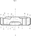
- Fig. 5 is a side view illustrating the first side surface 81 of the cutting insert 2 illustrated in Fig. 2 .
- the long surface 12 and the short surface 13 are inclined such that the opening of the recess 10 widens toward the lower surface 7.
- the lower surface 7 is formed substantially flat.
- the bottom surface 11 of the recess 10 is formed parallel to the lower surface 7. In other words, the bottom surface 11 of the recess 10 is formed at a substantially constant depth from the lower surface 7.
- Fig. 6 is a side view illustrating a modification example of the recess 10 illustrated in Fig. 5 .
- the bottom surface 11 of the recess 10 may be inclined with respect to the lower surface 7.
- the bottom surface 11 is formed so as to increase in depth toward the first vertex P.
- Fig. 7 is a perspective view illustrating the protrusion 20 with the cutting insert 2 removed. As illustrated in Fig. 7 , the protrusion 20 protrudes from the first wall surface 41 of the insert seat 4 toward the center of the insert seat 4.
- the side surface of the shim 43 is recessed in a shape that resembles the protrusion 20.
- the wall thickness of the back metal 30 can be increased as the back metal 30 is provided with the protrusion 20 having a shape that resembles the recess 10.
- the protrusion 20 is formed lower than the back metal 30.
- the upper portion of the protrusion 20 is close to the seat surface 40, and thus the upper portion of the protrusion 20 is less likely to be deformed than the upper portion of the back metal 30.
- Fig. 8 is a perspective view illustrating a state where the protrusion 20 abuts against the recess 10.
- a top surface 21 of the protrusion 20 and the bottom surface 11 of the recess 10 face each other with a gap in a state where the cutting insert 2 is mounted on the tool main body 3.
- the tip portion of the protrusion 20 abuts against the inner wall surface of the recess 10.
- the protrusion 20 is slightly deformed elastically and comes into surface contact with the inner wall surface of the recess 10.
- the two-dot chain line in Fig. 5 indicates an example of the region where the protrusion 20 and the recess 10 are in surface contact with each other.
- Fig. 9 is a side view illustrating a state where an inclined surface 22 of the protrusion 20 abuts against the recess 10.
- the protrusion 20 includes the inclined surface 22 inclined toward the first wall surface 41 and away from the seat surface 40 of the insert seat 4.
- the inclined surface 22 is disposed in the upper portion of the protrusion 20 and formed substantially parallel to the inner wall surface of the recess 10 (for example, the long surface 12).
- the inclined surface 22 comes into sliding contact with the recess 10 and the protrusion 20 is slightly deformed elastically.
- the wall thickness of the back metal 30 can be increased by the protrusion 20 protruding from the first wall surface 41 of the insert seat 4 as illustrated in Figs. 7 to 9 . Moreover, the position of the part where the back metal 30 supports the peripheral side surface 8 of the cutting insert 2 can be shifted to the thick protrusion 20 from the tip of the back metal 30 with the minimum thickness.
- the point contact of the insert changes to the surface contact of the protrusion 20, and thus the load on the back metal 30 can be dispersed.
- the protrusion 20 is not only thick but also shorter and less likely to be deformed than the tip of the back metal 30. Accordingly, the deformation of the back metal 30 can be suppressed and the life of the tool main body 3 can be lengthened.
- the cutting insert 2 can be stably fixed to the tool main body 3, and the positioning accuracy of the cutting edge can be improved.
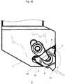
- Fig. 10 is a plan view illustrating a load acting on the back metal 30.
- a force F acts so as to rotate the cutting insert 2 about the through hole 9 fixed to the clamp member 5 and the back metal 30 that prevents the cutting insert 2 from rotating is burdened.
- the load on the back metal 30 is particularly large during cutting in which the force F acts only on one side of the cutting edge 61 (flank in-feed).
- the life of the tool main body 3 tends to be short in the flank in-feed illustrated in Fig. 10 .
- the cutting insert 2 of the present embodiment is significantly different from the cutting insert of the related art particularly in the flank in-feed, which is a strict condition for the tool main body 3, and is capable of significantly lengthening the life of the tool main body 3.
- the recess 10 is a bottomed hole that does not penetrate the upper surface 6. Accordingly, as illustrated in Figs. 5 and 6 , wall thickness can be ensured between the bottom surface 11 of the recess 10 and the upper surface 6. The rigidity of the cutting insert 2 can be ensured on the upper surface 6 where the cutting edge 61 is formed. As illustrated in Fig. 9 , the upper portion of the protrusion 20 is the inclined surface 22 substantially parallel to the recess 10. Accordingly, a large contact area can be ensured between the protrusion 20 and the recess 10 when the protrusion 20 is elastically deformed.
Landscapes
- Engineering & Computer Science (AREA)
- Mechanical Engineering (AREA)
- Cutting Tools, Boring Holders, And Turrets (AREA)
Abstract
Description
- This application relates to and claims priority from Japanese Patent Application No.
2020-004700 on (January 15, 2020 - The present invention relates to a cutting insert and a turning tool using the cutting insert.
- A turning tool includes an indexable cutting insert and a tool main body for fixing the cutting insert. In the turning tool suitable for thread cutting, grooving, or the like, a wedge-shaped thin-walled portion may be formed in the tip portion of the tool main body (see, for example,
Fig. 6 ofWO1995/007159 ). In the following description, such a wedge-shaped thin-walled portion will be referred to as a back metal. The back metal is positioned between an insert seat where the cutting insert is mounted and the tip surface of the tool main body. The back metal fixes the cutting insert together with another wall surface or abuts against the side surface of the cutting insert to prevent the cutting insert from rotating. - In this regard, an object of the invention is to provide a turning tool and a cutting insert capable of lengthening the life of a tool main body and stably fixable to the tool main body.
- A cutting insert according to one aspect of the invention includes an upper surface, a lower surface on a side opposite to the upper surface, and a peripheral side surface connecting the upper surface and the lower surface. A cutting edge is formed in at least a part of a first ridgeline where the upper surface and the peripheral side surface intersect. At least one bottomed recess recessed from the lower surface to the upper surface is formed in an outer peripheral surface of the lower surface. Each of the recesses is formed in a substantially triangular shape having a first vertex, a second vertex, and a third vertex. The first vertex and the second vertex are respectively positioned on a second ridgeline where the lower surface and the peripheral side surface intersect. The third vertex is positioned on the lower surface and separated from the second ridgeline.
- A turning tool according to one aspect of the invention includes a tool main body formed in a rod shape extending from a base end to a tip in addition to the cutting insert described above. A insert seat where the cutting insert is mountable is provided near the tip of the tool main body. The insert seat has a first wall surface facing the peripheral side surface of the cutting insert from the tip side. The tool main body has a back metal formed between the first wall surface and an end surface on the tip side. A protrusion protruding from the first wall surface and having a shape resembling the recess is formed on the back metal supporting the cutting insert.
- According to these aspects, the wall thickness of the back metal can be increased as the back metal is provided with the protrusion having a shape that resembles the recess. The protrusion of the back metal comes into surface contact with the cutting insert instead of the tip of the back metal coming into point contact with the cutting insert, and thus the load during cutting can be dispersed. By suppressing the deformation of the back metal, it is possible to provide a turning tool and a cutting insert capable of lengthening the life of the tool main body and stably fixable to the tool main body.
- In the aspect described above, the second ridgeline may be formed in a substantially equilateral triangle having a first side, a second side, and a third side. The single recess may be formed on each of the first side, the second side, and the third side.
- A substantially equilateral triangular cutting insert is economical because three corners can be used by 120 degrees rotation. On the other hand, in the substantially equilateral triangular cutting insert, the insert seat has a substantially equilateral triangle, and thus the back metal is likely to be thin. According to this aspect, it is possible to ensure the wall thickness of the back metal by providing the protrusion having a shape that resembles the recess even when the cutting insert has a substantially equilateral triangle
- In the aspect described above, the
recess 10 may include a long surface formed between the first vertex and the third vertex and a short surface formed between the second vertex and the third vertex. When the short surface is shorter than the long surface, an edge of the recess where the lower surface and the long surface of the recess formed on the first side intersect and that is a part near the first vertex may be formed in a straight line substantially orthogonal to the second side or the third side. - When the cutting insert is mounted on the tool main body by means of a clamp member, the cutting insert is pressed in a direction substantially orthogonal to the second or third side of the cutting insert. The protrusion is guided in the recess along the long surface of the recess. According to this aspect, the direction in which the cutting insert is pressed and the direction in which the protrusion is guided are parallel, and thus the cutting insert can be smoothly restrained.
- In the aspect described above, the insert seat further has a seat surface facing the lower surface of the cutting insert. It is preferable that at least a part of the protrusion is inclined toward the first wall surface and away from the seat surface.
- According to this aspect, the inclined surface provided in the upper portion of the protrusion comes into sliding contact substantially in parallel to the cutting insert. The inclined surface is capable of coming into surface contact with the cutting insert by slight elastic deformation.
- According to the invention, it is possible to provide the turning tool and the cutting insert capable of lengthening the life of the tool main body and stably fixable to the tool main body.
-
-
Fig. 1 is a perspective view illustrating an example of the turning tool according to an embodiment of the invention. -
Fig. 2 is a perspective view illustrating an example of the cutting insert illustrated inFig. 1 . -
Fig. 3 is a plan view illustrating the upper surface of the cutting insert illustrated inFig. 2 . -
Fig. 4 is a bottom view illustrating the lower surface of the cutting insert illustrated inFig. 2 . -
Fig. 5 is a side view illustrating a first side surface of the cutting insert illustrated inFig. 2 . -
Fig. 6 is a side view illustrating a modification example of the recess illustrated inFig. 5 . -
Fig. 7 is a perspective view illustrating a protrusion with the cutting insert removed. -
Fig. 8 is a perspective view illustrating a state where the protrusion abuts against the recess. -
Fig. 9 is a side view illustrating a state where the inclined surface of the protrusion abuts against the recess. -
Fig. 10 is a plan view illustrating a load acting on a back metal. - A preferred embodiment of the invention will be described with reference to the accompanying drawings. It should be noted that those having the same reference numerals in the drawings have the same or similar configurations. A
cutting insert 2 according to the embodiment of the invention has a bottomedrecess 10 recessed from anupper surface 6 toward an lower surface 7 (seeFig. 2 ). The wall thickness of aback metal 30 can be increased as aprotrusion 20 corresponding to therecess 10 is provided (seeFig. 7 ). Therecess 10 is formed in a substantially triangular shape having first to third vertices P, Q, and R (seeFig. 4 ) and fits with the protrusion 20 (seeFig. 8 ). Theprotrusion 20 comes into surface contact with therecess 10 after slight elastic deformation (seeFig. 9 ), and thus the load during cutting (seeFig. 10 ) can be dispersed. - The
recess 10 is a bottomed hole that is formed in thelower surface 7 and does not penetrate the upper surface 6 (seeFigs. 5 and6 ). When therecess 10 is provided, the space between therecess 10 and a throughhole 9 formed at the center of thecutting insert 2 is likely to be thin. In the present embodiment, wall thickness is ensured between abottom surface 11 of therecess 10 and theupper surface 6, and thus the rigidity of thecutting insert 2 can be ensured on theupper surface 6 where acutting edge 61 is formed (seeFig. 3 ). Hereinafter, each configuration will be described in detail with reference toFigs. 1 to 10 . -
Fig. 1 is a perspective view illustrating an example of aturning tool 1 according to the embodiment of the invention. As illustrated inFig. 1 , theturning tool 1 includes theindexable cutting insert 2 and a toolmain body 3 for fixing the cuttinginsert 2. The toolmain body 3 is formed in a rod shape extending from the base end to the tip. The shank that includes anend surface 31 on the base end side of the toolmain body 3 is fixed to, for example, a lathe tool rest. Ainsert seat 4 where the cuttinginsert 2 can be mounted is provided near the tip of the toolmain body 3. - The
insert seat 4 has aseat surface 40 facing thelower surface 7 of the cuttinginsert 2 and afirst wall surface 41 and asecond wall surface 42 erected from theseat surface 40. The wedge-shaped backmetal 30 is provided between thefirst wall surface 41 of theinsert seat 4 and anend surface 32 on the tip side of the toolmain body 3. Theback metal 30 supports the cuttinginsert 2, fixes the cuttinginsert 2, and prevents the cuttinginsert 2 from rotating. The shape of theback metal 30 will be described in detail later with reference toFigs. 7 to 9 . - In the illustrated example, an
indexable shim 43 is disposed between thelower surface 7 and theseat surface 40. Most of the toolmain body 3 including theinsert seat 4 is formed of, for example, steel. Theshim 43 is formed of, for example, cemented carbide and is less likely to be deformed than other parts formed of steel. When theshim 43 is interposed between thelower surface 7 and theseat surface 40, the damage-prone part is configured to be indexable and is unlikely to be deformed. Accordingly, the life of the toolmain body 3 can be lengthened. - In the illustrated example, the cutting
insert 2 is mounted in a clamp-on manner in which theupper surface 6 of the cuttinginsert 2 is pressed by aclamp member 5. It should be noted that the toolmain body 3 is not limited to the clamp-on type. The cuttinginsert 2 may be mounted in, for example, a screw-on manner in which theupper surface 6 of the cuttinginsert 2 is pressed by a screw head or may be of a lever lock type in which any one of corners A, B, and C of the cuttinginsert 2 is pushed into and tightened to the corner of theinsert seat 4. -
Fig. 2 is a perspective view illustrating an example of the cuttinginsert 2 illustrated inFig. 1 . In the present embodiment, the material of the cuttinginsert 2 is not particularly limited. Various cutting insert materials such as cemented carbide can be applied. As illustrated inFig. 2 , the cuttinginsert 2 has theupper surface 6, thelower surface 7 on the side that is opposite to theupper surface 6, and aperipheral side surface 8 connecting theupper surface 6 and thelower surface 7. The throughhole 9 penetrating theupper surface 6 and thelower surface 7 is formed in thecutting insert 2. - The
upper surface 6 and thelower surface 7 are formed rotationally symmetric with respect to the center of the through hole 9 (120 degrees symmetry in the illustrated example). In the following description, a central axis O of the cuttinginsert 2 is a straight line passing through the center of the throughhole 9, the side that is close to the central axis O is the central side of the cuttinginsert 2, and the side that is far from the central axis O is the outer peripheral side of the cuttinginsert 2. -
Fig. 3 is a plan view illustrating theupper surface 6 of the cuttinginsert 2 illustrated inFig. 2 . In the illustrated example, afirst ridgeline 60, where theupper surface 6 and theperipheral side surface 8 intersect, is formed in a substantially triangular shape. Thefirst ridgeline 60 includes thecutting edge 61 formed at each corner. Theupper surface 6 includes arake surface 62 facing thecutting edge 61 and achip breaker 63 formed closer to the central side of the cuttinginsert 2 than therake surface 62. In the illustrated example, thechip breaker 63 is formed on a curved surface continuous with therake surface 62. -
Fig. 4 is a bottom view illustrating thelower surface 7 of the cuttinginsert 2 illustrated inFig. 2 . In the illustrated example, asecond ridgeline 70, where thelower surface 7 and theperipheral side surface 8 intersect, is formed in a substantially equilateral triangle having the corners A, B, and C. Thesecond ridgeline 70 may be, for example, substantially square without being limited to the substantially equilateral triangle. The cuttinginsert 2 of the present embodiment has at least one bottomedrecess 10 recessed from thelower surface 7 toward theupper surface 6. - As illustrated in
Fig. 4 , therecess 10 is formed in the outer peripheral portion of thelower surface 7 with first to third sides AB, BC, and CA, which constitute thesecond ridgeline 70, cut out in part. In the illustrated example, onerecess 10 is formed on each of the sides AB, BC, and CA. A side on which therecess 10 is formed and a side on which therecess 10 is not formed may be mixed in thesingle cutting insert 2. - In the illustrated example, edges PR and QR of the
recess 10 formed on thelower surface 7 are formed in a substantially triangular shape having the first to third vertices P, Q, and R. The first and second vertices P and Q are positioned on thesecond ridgeline 70. The third vertex R is positioned closer to the central side of the cuttinginsert 2 than the first and second vertices P and Q on thelower surface 7. A side PQ includes a midpoint M of each of the sides AB, BC, and CA. - In the illustrated example, the inner wall surface of the
recess 10 is configured by thebottom surface 11, along surface 12, and ashort surface 13. Thelong surface 12 interconnects the first vertex P and the third vertex R. Theshort surface 13 interconnects the second vertex Q and the third vertex R. Thebottom surface 11 interconnects the long andshort surfaces peripheral side surface 8. The edge PR described above is a ridgeline where thelong surface 12 and thelower surface 7 intersect, and the edge QR described above is a ridgeline where theshort surface 13 and thelower surface 7 intersect. In the illustrated example, theshort surface 13 is formed shorter than thelong surface 12. A part X is at least half of the edge PR of therecess 10 connecting the first vertex P and the second vertex Q, is near the first vertex, and is formed in a straight line. - The straight line part X of the edge PR of the
recess 10 formed on the first side AB extends in a direction substantially orthogonal to the second side BC or the third side CA (second side BC in the illustrated example). Likewise, the straight line part X of the edge PR of therecess 10 formed on the second side BC is substantially orthogonal to the third side CA and the straight line part X of the edge PR of therecess 10 formed on the third side CA is substantially orthogonal to the first side AB. In therecess 10 formed on the first side AB, the first vertex P constituting thelong surface 12 is closer to the corner A than the second vertex Q constituting theshort surface 13. The second side BC to which the straight line part X of the edge PR of therecess 10 is orthogonal is opposite to the corner A. - The
peripheral side surface 8 described above includes afirst side surface 81 facing the first side AB of asecond ridgeline 70, asecond side surface 82 facing the second side BC, and athird side surface 83 facing the third side CA.Fig. 5 is a side view illustrating thefirst side surface 81 of the cuttinginsert 2 illustrated inFig. 2 . As illustrated inFig. 5 , thelong surface 12 and theshort surface 13 are inclined such that the opening of therecess 10 widens toward thelower surface 7. Thelower surface 7 is formed substantially flat. In the illustrated example, thebottom surface 11 of therecess 10 is formed parallel to thelower surface 7. In other words, thebottom surface 11 of therecess 10 is formed at a substantially constant depth from thelower surface 7. -
Fig. 6 is a side view illustrating a modification example of therecess 10 illustrated inFig. 5 . As illustrated inFig. 6 , thebottom surface 11 of therecess 10 may be inclined with respect to thelower surface 7. In the illustrated example, thebottom surface 11 is formed so as to increase in depth toward the first vertex P. - The
protrusion 20, which has a shape that resembles thelong surface 12 of therecess 10, is formed on thefirst wall surface 41 of theinsert seat 4 described above.Fig. 7 is a perspective view illustrating theprotrusion 20 with the cuttinginsert 2 removed. As illustrated inFig. 7 , theprotrusion 20 protrudes from thefirst wall surface 41 of theinsert seat 4 toward the center of theinsert seat 4. The side surface of theshim 43 is recessed in a shape that resembles theprotrusion 20. In the present embodiment, the wall thickness of theback metal 30 can be increased as theback metal 30 is provided with theprotrusion 20 having a shape that resembles therecess 10. At the height of theinsert seat 4 from theseat surface 40, theprotrusion 20 is formed lower than theback metal 30. The upper portion of theprotrusion 20 is close to theseat surface 40, and thus the upper portion of theprotrusion 20 is less likely to be deformed than the upper portion of theback metal 30. -
Fig. 8 is a perspective view illustrating a state where theprotrusion 20 abuts against therecess 10. As illustrated inFig. 8 , atop surface 21 of theprotrusion 20 and thebottom surface 11 of therecess 10 face each other with a gap in a state where the cuttinginsert 2 is mounted on the toolmain body 3. The tip portion of theprotrusion 20 abuts against the inner wall surface of therecess 10. When theprotrusion 20 abuts against the inner wall surface of therecess 10, theprotrusion 20 is slightly deformed elastically and comes into surface contact with the inner wall surface of therecess 10. The two-dot chain line inFig. 5 indicates an example of the region where theprotrusion 20 and therecess 10 are in surface contact with each other. -
Fig. 9 is a side view illustrating a state where aninclined surface 22 of theprotrusion 20 abuts against therecess 10. As illustrated inFig. 9 , theprotrusion 20 includes theinclined surface 22 inclined toward thefirst wall surface 41 and away from theseat surface 40 of theinsert seat 4. Theinclined surface 22 is disposed in the upper portion of theprotrusion 20 and formed substantially parallel to the inner wall surface of the recess 10 (for example, the long surface 12). When the cuttinginsert 2 is attached to theinsert seat 4, theinclined surface 22 comes into sliding contact with therecess 10 and theprotrusion 20 is slightly deformed elastically. - According to the cutting
insert 2 of the present embodiment configured as described above and theturning tool 1 provided with the cuttinginsert 2, the wall thickness of theback metal 30 can be increased by theprotrusion 20 protruding from thefirst wall surface 41 of theinsert seat 4 as illustrated inFigs. 7 to 9 . Moreover, the position of the part where theback metal 30 supports theperipheral side surface 8 of the cuttinginsert 2 can be shifted to thethick protrusion 20 from the tip of theback metal 30 with the minimum thickness. - The point contact of the insert changes to the surface contact of the
protrusion 20, and thus the load on theback metal 30 can be dispersed. Moreover, theprotrusion 20 is not only thick but also shorter and less likely to be deformed than the tip of theback metal 30. Accordingly, the deformation of theback metal 30 can be suppressed and the life of the toolmain body 3 can be lengthened. The cuttinginsert 2 can be stably fixed to the toolmain body 3, and the positioning accuracy of the cutting edge can be improved. -
Fig. 10 is a plan view illustrating a load acting on theback metal 30. During cutting, a force F acts so as to rotate the cuttinginsert 2 about the throughhole 9 fixed to theclamp member 5 and theback metal 30 that prevents the cuttinginsert 2 from rotating is burdened. As illustrated inFig. 10 , the load on theback metal 30 is particularly large during cutting in which the force F acts only on one side of the cutting edge 61 (flank in-feed). - In the cutting insert of the related art that lacks the
recess 10, the life of the toolmain body 3 tends to be short in the flank in-feed illustrated inFig. 10 . The cuttinginsert 2 of the present embodiment is significantly different from the cutting insert of the related art particularly in the flank in-feed, which is a strict condition for the toolmain body 3, and is capable of significantly lengthening the life of the toolmain body 3. - In the present embodiment, the
recess 10 is a bottomed hole that does not penetrate theupper surface 6. Accordingly, as illustrated inFigs. 5 and6 , wall thickness can be ensured between thebottom surface 11 of therecess 10 and theupper surface 6. The rigidity of the cuttinginsert 2 can be ensured on theupper surface 6 where thecutting edge 61 is formed. As illustrated inFig. 9 , the upper portion of theprotrusion 20 is theinclined surface 22 substantially parallel to therecess 10. Accordingly, a large contact area can be ensured between theprotrusion 20 and therecess 10 when theprotrusion 20 is elastically deformed. - The embodiment described above is to facilitate the understanding of the invention and is not to limit the interpretation of the invention. Each element included in the embodiment and the disposition, material, condition, shape, size, and so on thereof can be appropriately changed without being limited to the above exemplification. In addition, configurations illustrated in different embodiments can be partially replaced or combined.
- The embodiment described above is to facilitate the understanding of the invention and is not to limit the interpretation of the invention. Each element included in the embodiment and the disposition, material, condition, shape, size, and so on thereof can be appropriately changed without being limited to the above exemplification. In addition, configurations illustrated in different embodiments can be partially replaced or combined.
-
- 1
- Turning tool
- 2
- Cutting insert
- 3
- Tool main body
- 4
- Insert seat
- 5
- Clamp member
- 6
- Upper surface
- 7
- Lower surface
- 8
- Peripheral side surface
- 9
- Through hole
- 10
- Recess
- 11
- Bottom surface
- 12
- Long surface
- 13
- Short surface
- 20
- Protrusion
- 21
- Top surface
- 22
- Inclined surface
- 30
- Back metal
- 31
- Base end surface
- 32
- Tip surface
- 40
- Seat surface
- 41
- First wall surface
- 42
- Second wall surface
- 43
- Shim
- 60
- First ridgeline
- 61
- Cutting edge
- 62
- Rake surface
- 63
- Chip breaker
- 70
- Second ridgeline
- 81
- First side surface
- 82
- Second side surface
- 83
- Third side surface
- A, B, C
- Corner
- AB
- First side
- BC
- Second side
- CA
- Third side
- F
- Force acting during cutting
- O
- Central axis
- P
- First vertex
- Q
- Second vertex
- R
- Third vertex
- PR, RQ
- Edge
- X
- Straight line part
Claims (5)
- A cutting insert comprising:an upper surface;a lower surface on a side opposite to the upper surface; anda peripheral side surface connecting the upper surface and the lower surface, a cutting edge being formed in at least a part of a first ridgeline where the upper surface and the peripheral side surface intersect, whereinat least one bottomed recess recessed from the lower surface to the upper surface is formed in an outer peripheral portion of the lower surface, andeach of the recesses is formed in a substantially triangular shape having a first vertex and a second vertex respectively positioned on a second ridgeline where the lower surface and the peripheral side surface intersect and a third vertex positioned on the lower surface and separated from the second ridgeline.
- The cutting insert according to claim 1, wherein
the second ridgeline is formed in a substantially equilateral triangle having a first side, a second side, and a third side, and
the single recess is formed on each of the first side, the second side, and the third side. - The cutting insert according to claim 2, wherein
the recess includes a long surface formed between the first vertex and the third vertex and a short surface formed between the second vertex and the third vertex and shorter than the long surface, and
an edge of the recess where the lower surface and the long surface formed on the first side intersect and that is a part near the first vertex is formed in a straight line substantially orthogonal to the second side or the third side. - A turning tool comprising:the cutting insert according to any one of claims 1 to 3; anda tool main body formed in a rod shape extending from a base end to a tip with a insert seat where the cutting insert is mountable provided near the tip, whereinthe insert seat has a first wall surface facing the peripheral side surface of the cutting insert from the tip side,the tool main body has a back metal formed between the first wall surface and an end surface on the tip side and supports the cutting insert, anda protrusion protruding from the first wall surface and having a shape resembling the recess is formed on the back metal.
- The turning tool according to claim 4, wherein
the insert seat further has a seat surface facing the lower surface of the cutting insert, and
at least a part of the protrusion is inclined toward the first wall surface and away from the seat surface.
Applications Claiming Priority (1)
| Application Number | Priority Date | Filing Date | Title |
|---|---|---|---|
| JP2020004700A JP6919824B2 (en) | 2020-01-15 | 2020-01-15 | Cutting inserts and turning tools using the cutting inserts |
Publications (2)
| Publication Number | Publication Date |
|---|---|
| EP3851232A1 true EP3851232A1 (en) | 2021-07-21 |
| EP3851232B1 EP3851232B1 (en) | 2024-07-03 |
Family
ID=74184511
Family Applications (1)
| Application Number | Title | Priority Date | Filing Date |
|---|---|---|---|
| EP21151667.9A Active EP3851232B1 (en) | 2020-01-15 | 2021-01-14 | Cutting insert and turning tool with such a cutting insert |
Country Status (4)
| Country | Link |
|---|---|
| US (1) | US11491550B2 (en) |
| EP (1) | EP3851232B1 (en) |
| JP (1) | JP6919824B2 (en) |
| CN (1) | CN113118484B (en) |
Families Citing this family (3)
| Publication number | Priority date | Publication date | Assignee | Title |
|---|---|---|---|---|
| JP7004189B1 (en) * | 2021-04-15 | 2022-01-21 | 株式会社タンガロイ | Cutting inserts and cutting tools |
| US11717895B2 (en) * | 2021-05-21 | 2023-08-08 | Taegutec Ltd. | Cutting insert and cutting tool assembly including same |
| IL305453B2 (en) * | 2023-08-24 | 2025-02-01 | Carmex Prec Tools Limited | Cutting insert and tool holder therefor |
Citations (7)
| Publication number | Priority date | Publication date | Assignee | Title |
|---|---|---|---|---|
| US3629919A (en) * | 1969-09-17 | 1971-12-28 | David J Trevarrow Jr | Tool and tool holder assembly |
| JPH04300114A (en) * | 1991-03-28 | 1992-10-23 | Mitsubishi Materials Corp | Rolling and cutting tool |
| WO1995007159A1 (en) | 1993-09-10 | 1995-03-16 | Sandvik Ab | Thread cutting insert with chip breakers |
| US6213691B1 (en) * | 1997-03-07 | 2001-04-10 | Felix Leeb | Circular drill cutter with indexable inserts and pertaining tip seats |
| US20040265074A1 (en) * | 2003-03-14 | 2004-12-30 | Sandvik Ab | Tool and cutting insert for the fine turning of grooves in workpieces |
| EP2664399A1 (en) * | 2012-05-15 | 2013-11-20 | VARGUS Ltd. | Cutting tool, cutting insert and tool holder |
| CN103418823A (en) * | 2013-09-03 | 2013-12-04 | 株洲华锐硬质合金工具有限责任公司 | Blade for milling and matched milling cutter of blade |
Family Cites Families (19)
| Publication number | Priority date | Publication date | Assignee | Title |
|---|---|---|---|---|
| DE3303263C2 (en) * | 1983-02-01 | 1985-12-19 | Fried. Krupp Gmbh, 4300 Essen | Nine-corner indexable insert |
| SE445094B (en) * | 1984-10-10 | 1986-06-02 | Santrade Ltd | HAPPENS WITH STUDYTOR ON ITS SIDE |
| US5032050A (en) * | 1987-09-04 | 1991-07-16 | Kennametal Inc. | On-edge cutting insert with chip control |
| SE509363C2 (en) * | 1995-09-25 | 1999-01-18 | Sandvik Ab | Fixing device removes cutting plates and cutting plate intended for such device |
| SE510851C2 (en) * | 1996-12-23 | 1999-06-28 | Sandvik Ab | Cuts and holders for cutting metalworking |
| ES2276719T3 (en) * | 2000-02-05 | 2007-07-01 | Ceramtec Ag Innovative Ceramic Engineering | CUTTER PLATE. |
| JP4155838B2 (en) * | 2003-02-14 | 2008-09-24 | 住友電工ハードメタル株式会社 | Replaceable blade tip and cutting tool using the same |
| SE526109C2 (en) * | 2003-03-17 | 2005-07-05 | Seco Tools Ab | Milling tools and indexable inserts with cooperating projections and recesses |
| SE529330C2 (en) * | 2005-11-21 | 2007-07-10 | Sandvik Intellectual Property | Tools and cutting body for chip separating machining with elastic connection between cutting body and holder |
| DE102006028062B4 (en) * | 2006-06-12 | 2008-09-18 | Vargus Ltd. | Indexable insert |
| SE530701C2 (en) * | 2006-12-21 | 2008-08-19 | Sandvik Intellectual Property | Turning tools and lathe inserts where the engaging means of the insert are located in the triangle |
| SE531855C2 (en) * | 2007-12-20 | 2009-08-25 | Seco Tools Ab | Indexable lathe insert and a cutting tool including such insert |
| CN104640657B (en) * | 2012-09-20 | 2017-03-08 | 株式会社钨钛合金 | Cutting tip and bit replacing formula rotary cutting tool |
| JP6264833B2 (en) * | 2012-11-22 | 2018-01-24 | 三菱マテリアル株式会社 | Cutting insert and manufacturing method thereof |
| EP3281732B1 (en) * | 2015-04-06 | 2022-12-14 | Tungaloy Corporation | Cutting insert and cutting-edge-replaceable cutting tool |
| DE102016008089A1 (en) * | 2016-06-30 | 2018-01-04 | Iscar Ltd. | Cutting tool and triangular indexable cutting insert for it |
| CN108136521B (en) * | 2016-09-27 | 2022-04-26 | 株式会社泰珂洛 | Cutting insert and cutting tool |
| JP6730442B2 (en) * | 2016-10-31 | 2020-07-29 | 京セラ株式会社 | Manufacturing method of cutting insert, cutting tool, and cut product |
| JP6776199B2 (en) * | 2017-07-18 | 2020-10-28 | 日本特殊陶業株式会社 | Cutting insert |
-
2020
- 2020-01-15 JP JP2020004700A patent/JP6919824B2/en active Active
-
2021
- 2021-01-05 CN CN202110005833.7A patent/CN113118484B/en active Active
- 2021-01-06 US US17/142,379 patent/US11491550B2/en active Active
- 2021-01-14 EP EP21151667.9A patent/EP3851232B1/en active Active
Patent Citations (7)
| Publication number | Priority date | Publication date | Assignee | Title |
|---|---|---|---|---|
| US3629919A (en) * | 1969-09-17 | 1971-12-28 | David J Trevarrow Jr | Tool and tool holder assembly |
| JPH04300114A (en) * | 1991-03-28 | 1992-10-23 | Mitsubishi Materials Corp | Rolling and cutting tool |
| WO1995007159A1 (en) | 1993-09-10 | 1995-03-16 | Sandvik Ab | Thread cutting insert with chip breakers |
| US6213691B1 (en) * | 1997-03-07 | 2001-04-10 | Felix Leeb | Circular drill cutter with indexable inserts and pertaining tip seats |
| US20040265074A1 (en) * | 2003-03-14 | 2004-12-30 | Sandvik Ab | Tool and cutting insert for the fine turning of grooves in workpieces |
| EP2664399A1 (en) * | 2012-05-15 | 2013-11-20 | VARGUS Ltd. | Cutting tool, cutting insert and tool holder |
| CN103418823A (en) * | 2013-09-03 | 2013-12-04 | 株洲华锐硬质合金工具有限责任公司 | Blade for milling and matched milling cutter of blade |
Also Published As
| Publication number | Publication date |
|---|---|
| JP2021109304A (en) | 2021-08-02 |
| CN113118484A (en) | 2021-07-16 |
| US20210213540A1 (en) | 2021-07-15 |
| JP6919824B2 (en) | 2021-08-18 |
| EP3851232B1 (en) | 2024-07-03 |
| CN113118484B (en) | 2023-12-26 |
| US11491550B2 (en) | 2022-11-08 |
Similar Documents
| Publication | Publication Date | Title |
|---|---|---|
| EP1813371B1 (en) | Insert type cutting tool, insert therefor and method for attaching insert to tool main body | |
| US11491550B2 (en) | Cutting insert and turning tool using cutting insert | |
| AU2003207967B2 (en) | Metal cutting tool | |
| US9623493B2 (en) | Double-sided ball end mill cutting insert and tool therefor | |
| RU2354511C2 (en) | Tangential cutting plate and milling tool | |
| KR101323558B1 (en) | Insert with a mounting hole and toolholder including a cutting insert | |
| JP3057781B2 (en) | Indexable tip | |
| US20050244233A1 (en) | A cutting insert, a cutting tool, a shim and a method | |
| JP2016539010A (en) | Positionable milling insert with side support indentation and milling tool | |
| EP2581157A1 (en) | Cutting tool for grooving and parting operations | |
| JPWO2019073716A1 (en) | cartridge | |
| KR20220130718A (en) | Rectangular-shaped inserts for bar peeling and insert-holder tools therefor | |
| US20090226267A1 (en) | Cutting insert with threaded hole and cutting tool therefor | |
| EP4129546A1 (en) | Cutting insert and blade-tip-replaceable cutting tool | |
| EP0519480B1 (en) | Throw-away cutting tool | |
| JP2573098Y2 (en) | Indexable cutting tools | |
| KR100473417B1 (en) | Milling cutting tool | |
| JP2002018607A (en) | Indexable inserts and cutting tools | |
| JPH10328909A (en) | Throw-away chip and holder thereof | |
| JP2018187756A (en) | Cutting tool | |
| JP2002239814A (en) | Indexable tip | |
| JPH0516010U (en) | Throwaway cutting tool | |
| JPH0516009U (en) | Throwaway cutting tool |
Legal Events
| Date | Code | Title | Description |
|---|---|---|---|
| PUAI | Public reference made under article 153(3) epc to a published international application that has entered the european phase |
Free format text: ORIGINAL CODE: 0009012 |
|
| STAA | Information on the status of an ep patent application or granted ep patent |
Free format text: STATUS: REQUEST FOR EXAMINATION WAS MADE |
|
| 17P | Request for examination filed |
Effective date: 20210212 |
|
| AK | Designated contracting states |
Kind code of ref document: A1 Designated state(s): AL AT BE BG CH CY CZ DE DK EE ES FI FR GB GR HR HU IE IS IT LI LT LU LV MC MK MT NL NO PL PT RO RS SE SI SK SM TR |
|
| GRAP | Despatch of communication of intention to grant a patent |
Free format text: ORIGINAL CODE: EPIDOSNIGR1 |
|
| STAA | Information on the status of an ep patent application or granted ep patent |
Free format text: STATUS: GRANT OF PATENT IS INTENDED |
|
| INTG | Intention to grant announced |
Effective date: 20240130 |
|
| RIN1 | Information on inventor provided before grant (corrected) |
Inventor name: OTSUKA, JUN Inventor name: IDA, TAKEHIRO |
|
| GRAS | Grant fee paid |
Free format text: ORIGINAL CODE: EPIDOSNIGR3 |
|
| GRAA | (expected) grant |
Free format text: ORIGINAL CODE: 0009210 |
|
| STAA | Information on the status of an ep patent application or granted ep patent |
Free format text: STATUS: THE PATENT HAS BEEN GRANTED |
|
| AK | Designated contracting states |
Kind code of ref document: B1 Designated state(s): AL AT BE BG CH CY CZ DE DK EE ES FI FR GB GR HR HU IE IS IT LI LT LU LV MC MK MT NL NO PL PT RO RS SE SI SK SM TR |
|
| REG | Reference to a national code |
Ref country code: CH Ref legal event code: EP |
|
| REG | Reference to a national code |
Ref country code: DE Ref legal event code: R096 Ref document number: 602021014977 Country of ref document: DE |
|
| REG | Reference to a national code |
Ref country code: LT Ref legal event code: MG9D |
|
| REG | Reference to a national code |
Ref country code: NL Ref legal event code: MP Effective date: 20240703 |
|
| PG25 | Lapsed in a contracting state [announced via postgrant information from national office to epo] |
Ref country code: PT Free format text: LAPSE BECAUSE OF FAILURE TO SUBMIT A TRANSLATION OF THE DESCRIPTION OR TO PAY THE FEE WITHIN THE PRESCRIBED TIME-LIMIT Effective date: 20241104 |
|
| REG | Reference to a national code |
Ref country code: AT Ref legal event code: MK05 Ref document number: 1699317 Country of ref document: AT Kind code of ref document: T Effective date: 20240703 |
|
| PG25 | Lapsed in a contracting state [announced via postgrant information from national office to epo] |
Ref country code: NL Free format text: LAPSE BECAUSE OF FAILURE TO SUBMIT A TRANSLATION OF THE DESCRIPTION OR TO PAY THE FEE WITHIN THE PRESCRIBED TIME-LIMIT Effective date: 20240703 |
|
| PG25 | Lapsed in a contracting state [announced via postgrant information from national office to epo] |
Ref country code: PT Free format text: LAPSE BECAUSE OF FAILURE TO SUBMIT A TRANSLATION OF THE DESCRIPTION OR TO PAY THE FEE WITHIN THE PRESCRIBED TIME-LIMIT Effective date: 20241104 Ref country code: NL Free format text: LAPSE BECAUSE OF FAILURE TO SUBMIT A TRANSLATION OF THE DESCRIPTION OR TO PAY THE FEE WITHIN THE PRESCRIBED TIME-LIMIT Effective date: 20240703 |
|
| PG25 | Lapsed in a contracting state [announced via postgrant information from national office to epo] |
Ref country code: NO Free format text: LAPSE BECAUSE OF FAILURE TO SUBMIT A TRANSLATION OF THE DESCRIPTION OR TO PAY THE FEE WITHIN THE PRESCRIBED TIME-LIMIT Effective date: 20241003 |
|
| PG25 | Lapsed in a contracting state [announced via postgrant information from national office to epo] |
Ref country code: FI Free format text: LAPSE BECAUSE OF FAILURE TO SUBMIT A TRANSLATION OF THE DESCRIPTION OR TO PAY THE FEE WITHIN THE PRESCRIBED TIME-LIMIT Effective date: 20240703 Ref country code: GR Free format text: LAPSE BECAUSE OF FAILURE TO SUBMIT A TRANSLATION OF THE DESCRIPTION OR TO PAY THE FEE WITHIN THE PRESCRIBED TIME-LIMIT Effective date: 20241004 Ref country code: PL Free format text: LAPSE BECAUSE OF FAILURE TO SUBMIT A TRANSLATION OF THE DESCRIPTION OR TO PAY THE FEE WITHIN THE PRESCRIBED TIME-LIMIT Effective date: 20240703 |
|
| PG25 | Lapsed in a contracting state [announced via postgrant information from national office to epo] |
Ref country code: BG Free format text: LAPSE BECAUSE OF FAILURE TO SUBMIT A TRANSLATION OF THE DESCRIPTION OR TO PAY THE FEE WITHIN THE PRESCRIBED TIME-LIMIT Effective date: 20240703 |
|
| PG25 | Lapsed in a contracting state [announced via postgrant information from national office to epo] |
Ref country code: LV Free format text: LAPSE BECAUSE OF FAILURE TO SUBMIT A TRANSLATION OF THE DESCRIPTION OR TO PAY THE FEE WITHIN THE PRESCRIBED TIME-LIMIT Effective date: 20240703 |
|
| PG25 | Lapsed in a contracting state [announced via postgrant information from national office to epo] |
Ref country code: IS Free format text: LAPSE BECAUSE OF FAILURE TO SUBMIT A TRANSLATION OF THE DESCRIPTION OR TO PAY THE FEE WITHIN THE PRESCRIBED TIME-LIMIT Effective date: 20241103 Ref country code: AT Free format text: LAPSE BECAUSE OF FAILURE TO SUBMIT A TRANSLATION OF THE DESCRIPTION OR TO PAY THE FEE WITHIN THE PRESCRIBED TIME-LIMIT Effective date: 20240703 |
|
| PG25 | Lapsed in a contracting state [announced via postgrant information from national office to epo] |
Ref country code: HR Free format text: LAPSE BECAUSE OF FAILURE TO SUBMIT A TRANSLATION OF THE DESCRIPTION OR TO PAY THE FEE WITHIN THE PRESCRIBED TIME-LIMIT Effective date: 20240703 Ref country code: CZ Free format text: LAPSE BECAUSE OF FAILURE TO SUBMIT A TRANSLATION OF THE DESCRIPTION OR TO PAY THE FEE WITHIN THE PRESCRIBED TIME-LIMIT Effective date: 20240703 |
|
| PG25 | Lapsed in a contracting state [announced via postgrant information from national office to epo] |
Ref country code: ES Free format text: LAPSE BECAUSE OF FAILURE TO SUBMIT A TRANSLATION OF THE DESCRIPTION OR TO PAY THE FEE WITHIN THE PRESCRIBED TIME-LIMIT Effective date: 20240703 Ref country code: RS Free format text: LAPSE BECAUSE OF FAILURE TO SUBMIT A TRANSLATION OF THE DESCRIPTION OR TO PAY THE FEE WITHIN THE PRESCRIBED TIME-LIMIT Effective date: 20241003 |
|
| PG25 | Lapsed in a contracting state [announced via postgrant information from national office to epo] |
Ref country code: RS Free format text: LAPSE BECAUSE OF FAILURE TO SUBMIT A TRANSLATION OF THE DESCRIPTION OR TO PAY THE FEE WITHIN THE PRESCRIBED TIME-LIMIT Effective date: 20241003 Ref country code: PL Free format text: LAPSE BECAUSE OF FAILURE TO SUBMIT A TRANSLATION OF THE DESCRIPTION OR TO PAY THE FEE WITHIN THE PRESCRIBED TIME-LIMIT Effective date: 20240703 Ref country code: NO Free format text: LAPSE BECAUSE OF FAILURE TO SUBMIT A TRANSLATION OF THE DESCRIPTION OR TO PAY THE FEE WITHIN THE PRESCRIBED TIME-LIMIT Effective date: 20241003 Ref country code: LV Free format text: LAPSE BECAUSE OF FAILURE TO SUBMIT A TRANSLATION OF THE DESCRIPTION OR TO PAY THE FEE WITHIN THE PRESCRIBED TIME-LIMIT Effective date: 20240703 Ref country code: IS Free format text: LAPSE BECAUSE OF FAILURE TO SUBMIT A TRANSLATION OF THE DESCRIPTION OR TO PAY THE FEE WITHIN THE PRESCRIBED TIME-LIMIT Effective date: 20241103 Ref country code: HR Free format text: LAPSE BECAUSE OF FAILURE TO SUBMIT A TRANSLATION OF THE DESCRIPTION OR TO PAY THE FEE WITHIN THE PRESCRIBED TIME-LIMIT Effective date: 20240703 Ref country code: GR Free format text: LAPSE BECAUSE OF FAILURE TO SUBMIT A TRANSLATION OF THE DESCRIPTION OR TO PAY THE FEE WITHIN THE PRESCRIBED TIME-LIMIT Effective date: 20241004 Ref country code: FI Free format text: LAPSE BECAUSE OF FAILURE TO SUBMIT A TRANSLATION OF THE DESCRIPTION OR TO PAY THE FEE WITHIN THE PRESCRIBED TIME-LIMIT Effective date: 20240703 Ref country code: ES Free format text: LAPSE BECAUSE OF FAILURE TO SUBMIT A TRANSLATION OF THE DESCRIPTION OR TO PAY THE FEE WITHIN THE PRESCRIBED TIME-LIMIT Effective date: 20240703 Ref country code: CZ Free format text: LAPSE BECAUSE OF FAILURE TO SUBMIT A TRANSLATION OF THE DESCRIPTION OR TO PAY THE FEE WITHIN THE PRESCRIBED TIME-LIMIT Effective date: 20240703 Ref country code: BG Free format text: LAPSE BECAUSE OF FAILURE TO SUBMIT A TRANSLATION OF THE DESCRIPTION OR TO PAY THE FEE WITHIN THE PRESCRIBED TIME-LIMIT Effective date: 20240703 Ref country code: AT Free format text: LAPSE BECAUSE OF FAILURE TO SUBMIT A TRANSLATION OF THE DESCRIPTION OR TO PAY THE FEE WITHIN THE PRESCRIBED TIME-LIMIT Effective date: 20240703 |
|
| REG | Reference to a national code |
Ref country code: DE Ref legal event code: R097 Ref document number: 602021014977 Country of ref document: DE |
|
| PG25 | Lapsed in a contracting state [announced via postgrant information from national office to epo] |
Ref country code: RO Free format text: LAPSE BECAUSE OF FAILURE TO SUBMIT A TRANSLATION OF THE DESCRIPTION OR TO PAY THE FEE WITHIN THE PRESCRIBED TIME-LIMIT Effective date: 20240703 Ref country code: DK Free format text: LAPSE BECAUSE OF FAILURE TO SUBMIT A TRANSLATION OF THE DESCRIPTION OR TO PAY THE FEE WITHIN THE PRESCRIBED TIME-LIMIT Effective date: 20240703 Ref country code: SM Free format text: LAPSE BECAUSE OF FAILURE TO SUBMIT A TRANSLATION OF THE DESCRIPTION OR TO PAY THE FEE WITHIN THE PRESCRIBED TIME-LIMIT Effective date: 20240703 |
|
| PG25 | Lapsed in a contracting state [announced via postgrant information from national office to epo] |
Ref country code: EE Free format text: LAPSE BECAUSE OF FAILURE TO SUBMIT A TRANSLATION OF THE DESCRIPTION OR TO PAY THE FEE WITHIN THE PRESCRIBED TIME-LIMIT Effective date: 20240703 |
|
| PG25 | Lapsed in a contracting state [announced via postgrant information from national office to epo] |
Ref country code: IT Free format text: LAPSE BECAUSE OF FAILURE TO SUBMIT A TRANSLATION OF THE DESCRIPTION OR TO PAY THE FEE WITHIN THE PRESCRIBED TIME-LIMIT Effective date: 20240703 Ref country code: SK Free format text: LAPSE BECAUSE OF FAILURE TO SUBMIT A TRANSLATION OF THE DESCRIPTION OR TO PAY THE FEE WITHIN THE PRESCRIBED TIME-LIMIT Effective date: 20240703 |
|
| PLBE | No opposition filed within time limit |
Free format text: ORIGINAL CODE: 0009261 |
|
| STAA | Information on the status of an ep patent application or granted ep patent |
Free format text: STATUS: NO OPPOSITION FILED WITHIN TIME LIMIT |
|
| 26N | No opposition filed |
Effective date: 20250404 |
|
| REG | Reference to a national code |
Ref country code: CH Ref legal event code: PL |
|
| PG25 | Lapsed in a contracting state [announced via postgrant information from national office to epo] |
Ref country code: SE Free format text: LAPSE BECAUSE OF FAILURE TO SUBMIT A TRANSLATION OF THE DESCRIPTION OR TO PAY THE FEE WITHIN THE PRESCRIBED TIME-LIMIT Effective date: 20240703 |
|
| PG25 | Lapsed in a contracting state [announced via postgrant information from national office to epo] |
Ref country code: LU Free format text: LAPSE BECAUSE OF NON-PAYMENT OF DUE FEES Effective date: 20250114 Ref country code: MC Free format text: LAPSE BECAUSE OF FAILURE TO SUBMIT A TRANSLATION OF THE DESCRIPTION OR TO PAY THE FEE WITHIN THE PRESCRIBED TIME-LIMIT Effective date: 20240703 |
|
| GBPC | Gb: european patent ceased through non-payment of renewal fee |
Effective date: 20250114 |
|
| PG25 | Lapsed in a contracting state [announced via postgrant information from national office to epo] |
Ref country code: GB Free format text: LAPSE BECAUSE OF NON-PAYMENT OF DUE FEES Effective date: 20250114 Ref country code: BE Free format text: LAPSE BECAUSE OF NON-PAYMENT OF DUE FEES Effective date: 20250131 |
|
| PG25 | Lapsed in a contracting state [announced via postgrant information from national office to epo] |
Ref country code: FR Free format text: LAPSE BECAUSE OF NON-PAYMENT OF DUE FEES Effective date: 20250131 |
|
| PG25 | Lapsed in a contracting state [announced via postgrant information from national office to epo] |
Ref country code: CH Free format text: LAPSE BECAUSE OF NON-PAYMENT OF DUE FEES Effective date: 20250131 |
|
| REG | Reference to a national code |
Ref country code: BE Ref legal event code: MM Effective date: 20250131 |
|
| PG25 | Lapsed in a contracting state [announced via postgrant information from national office to epo] |
Ref country code: IE Free format text: LAPSE BECAUSE OF NON-PAYMENT OF DUE FEES Effective date: 20250114 |
|
| PGFP | Annual fee paid to national office [announced via postgrant information from national office to epo] |
Ref country code: DE Payment date: 20251203 Year of fee payment: 6 |