EP3851200A1 - Compressed-fluid discharge control device - Google Patents
Compressed-fluid discharge control device Download PDFInfo
- Publication number
- EP3851200A1 EP3851200A1 EP18933642.3A EP18933642A EP3851200A1 EP 3851200 A1 EP3851200 A1 EP 3851200A1 EP 18933642 A EP18933642 A EP 18933642A EP 3851200 A1 EP3851200 A1 EP 3851200A1
- Authority
- EP
- European Patent Office
- Prior art keywords
- valve
- compressed
- chamber
- pilot
- discharge
- Prior art date
- Legal status (The legal status is an assumption and is not a legal conclusion. Google has not performed a legal analysis and makes no representation as to the accuracy of the status listed.)
- Granted
Links
Images




Classifications
-
- B—PERFORMING OPERATIONS; TRANSPORTING
- B05—SPRAYING OR ATOMISING IN GENERAL; APPLYING FLUENT MATERIALS TO SURFACES, IN GENERAL
- B05B—SPRAYING APPARATUS; ATOMISING APPARATUS; NOZZLES
- B05B1/00—Nozzles, spray heads or other outlets, with or without auxiliary devices such as valves, heating means
- B05B1/30—Nozzles, spray heads or other outlets, with or without auxiliary devices such as valves, heating means designed to control volume of flow, e.g. with adjustable passages
-
- B—PERFORMING OPERATIONS; TRANSPORTING
- B05—SPRAYING OR ATOMISING IN GENERAL; APPLYING FLUENT MATERIALS TO SURFACES, IN GENERAL
- B05B—SPRAYING APPARATUS; ATOMISING APPARATUS; NOZZLES
- B05B1/00—Nozzles, spray heads or other outlets, with or without auxiliary devices such as valves, heating means
- B05B1/005—Nozzles or other outlets specially adapted for discharging one or more gases
-
- B—PERFORMING OPERATIONS; TRANSPORTING
- B05—SPRAYING OR ATOMISING IN GENERAL; APPLYING FLUENT MATERIALS TO SURFACES, IN GENERAL
- B05B—SPRAYING APPARATUS; ATOMISING APPARATUS; NOZZLES
- B05B1/00—Nozzles, spray heads or other outlets, with or without auxiliary devices such as valves, heating means
- B05B1/30—Nozzles, spray heads or other outlets, with or without auxiliary devices such as valves, heating means designed to control volume of flow, e.g. with adjustable passages
- B05B1/3006—Nozzles, spray heads or other outlets, with or without auxiliary devices such as valves, heating means designed to control volume of flow, e.g. with adjustable passages the controlling element being actuated by the pressure of the fluid to be sprayed
-
- B—PERFORMING OPERATIONS; TRANSPORTING
- B05—SPRAYING OR ATOMISING IN GENERAL; APPLYING FLUENT MATERIALS TO SURFACES, IN GENERAL
- B05B—SPRAYING APPARATUS; ATOMISING APPARATUS; NOZZLES
- B05B1/00—Nozzles, spray heads or other outlets, with or without auxiliary devices such as valves, heating means
- B05B1/30—Nozzles, spray heads or other outlets, with or without auxiliary devices such as valves, heating means designed to control volume of flow, e.g. with adjustable passages
- B05B1/3033—Nozzles, spray heads or other outlets, with or without auxiliary devices such as valves, heating means designed to control volume of flow, e.g. with adjustable passages the control being effected by relative coaxial longitudinal movement of the controlling element and the spray head
- B05B1/304—Nozzles, spray heads or other outlets, with or without auxiliary devices such as valves, heating means designed to control volume of flow, e.g. with adjustable passages the control being effected by relative coaxial longitudinal movement of the controlling element and the spray head the controlling element being a lift valve
- B05B1/3046—Nozzles, spray heads or other outlets, with or without auxiliary devices such as valves, heating means designed to control volume of flow, e.g. with adjustable passages the control being effected by relative coaxial longitudinal movement of the controlling element and the spray head the controlling element being a lift valve the valve element, e.g. a needle, co-operating with a valve seat located downstream of the valve element and its actuating means, generally in the proximity of the outlet orifice
- B05B1/3053—Nozzles, spray heads or other outlets, with or without auxiliary devices such as valves, heating means designed to control volume of flow, e.g. with adjustable passages the control being effected by relative coaxial longitudinal movement of the controlling element and the spray head the controlling element being a lift valve the valve element, e.g. a needle, co-operating with a valve seat located downstream of the valve element and its actuating means, generally in the proximity of the outlet orifice the actuating means being a solenoid
-
- B—PERFORMING OPERATIONS; TRANSPORTING
- B05—SPRAYING OR ATOMISING IN GENERAL; APPLYING FLUENT MATERIALS TO SURFACES, IN GENERAL
- B05B—SPRAYING APPARATUS; ATOMISING APPARATUS; NOZZLES
- B05B1/00—Nozzles, spray heads or other outlets, with or without auxiliary devices such as valves, heating means
- B05B1/30—Nozzles, spray heads or other outlets, with or without auxiliary devices such as valves, heating means designed to control volume of flow, e.g. with adjustable passages
- B05B1/3033—Nozzles, spray heads or other outlets, with or without auxiliary devices such as valves, heating means designed to control volume of flow, e.g. with adjustable passages the control being effected by relative coaxial longitudinal movement of the controlling element and the spray head
- B05B1/304—Nozzles, spray heads or other outlets, with or without auxiliary devices such as valves, heating means designed to control volume of flow, e.g. with adjustable passages the control being effected by relative coaxial longitudinal movement of the controlling element and the spray head the controlling element being a lift valve
- B05B1/3046—Nozzles, spray heads or other outlets, with or without auxiliary devices such as valves, heating means designed to control volume of flow, e.g. with adjustable passages the control being effected by relative coaxial longitudinal movement of the controlling element and the spray head the controlling element being a lift valve the valve element, e.g. a needle, co-operating with a valve seat located downstream of the valve element and its actuating means, generally in the proximity of the outlet orifice
- B05B1/306—Nozzles, spray heads or other outlets, with or without auxiliary devices such as valves, heating means designed to control volume of flow, e.g. with adjustable passages the control being effected by relative coaxial longitudinal movement of the controlling element and the spray head the controlling element being a lift valve the valve element, e.g. a needle, co-operating with a valve seat located downstream of the valve element and its actuating means, generally in the proximity of the outlet orifice the actuating means being a fluid
-
- B—PERFORMING OPERATIONS; TRANSPORTING
- B05—SPRAYING OR ATOMISING IN GENERAL; APPLYING FLUENT MATERIALS TO SURFACES, IN GENERAL
- B05B—SPRAYING APPARATUS; ATOMISING APPARATUS; NOZZLES
- B05B12/00—Arrangements for controlling delivery; Arrangements for controlling the spray area
- B05B12/08—Arrangements for controlling delivery; Arrangements for controlling the spray area responsive to condition of liquid or other fluent material to be discharged, of ambient medium or of target ; responsive to condition of spray devices or of supply means, e.g. pipes, pumps or their drive means
- B05B12/085—Arrangements for controlling delivery; Arrangements for controlling the spray area responsive to condition of liquid or other fluent material to be discharged, of ambient medium or of target ; responsive to condition of spray devices or of supply means, e.g. pipes, pumps or their drive means responsive to flow or pressure of liquid or other fluent material to be discharged
- B05B12/087—Flow or presssure regulators, i.e. non-electric unitary devices comprising a sensing element, e.g. a piston or a membrane, and a controlling element, e.g. a valve
- B05B12/088—Flow or presssure regulators, i.e. non-electric unitary devices comprising a sensing element, e.g. a piston or a membrane, and a controlling element, e.g. a valve the sensing element being a flexible member, e.g. membrane, diaphragm, bellows
-
- B—PERFORMING OPERATIONS; TRANSPORTING
- B05—SPRAYING OR ATOMISING IN GENERAL; APPLYING FLUENT MATERIALS TO SURFACES, IN GENERAL
- B05B—SPRAYING APPARATUS; ATOMISING APPARATUS; NOZZLES
- B05B9/00—Spraying apparatus for discharge of liquids or other fluent material, without essentially mixing with gas or vapour
- B05B9/03—Spraying apparatus for discharge of liquids or other fluent material, without essentially mixing with gas or vapour characterised by means for supplying liquid or other fluent material
- B05B9/04—Spraying apparatus for discharge of liquids or other fluent material, without essentially mixing with gas or vapour characterised by means for supplying liquid or other fluent material with pressurised or compressible container; with pump
-
- F—MECHANICAL ENGINEERING; LIGHTING; HEATING; WEAPONS; BLASTING
- F16—ENGINEERING ELEMENTS AND UNITS; GENERAL MEASURES FOR PRODUCING AND MAINTAINING EFFECTIVE FUNCTIONING OF MACHINES OR INSTALLATIONS; THERMAL INSULATION IN GENERAL
- F16K—VALVES; TAPS; COCKS; ACTUATING-FLOATS; DEVICES FOR VENTING OR AERATING
- F16K1/00—Lift valves or globe valves, i.e. cut-off apparatus with closure members having at least a component of their opening and closing motion perpendicular to the closing faces
- F16K1/32—Details
- F16K1/52—Means for additional adjustment of the rate of flow
- F16K1/523—Means for additional adjustment of the rate of flow for limiting the maximum flow rate, using a stop
-
- F—MECHANICAL ENGINEERING; LIGHTING; HEATING; WEAPONS; BLASTING
- F16—ENGINEERING ELEMENTS AND UNITS; GENERAL MEASURES FOR PRODUCING AND MAINTAINING EFFECTIVE FUNCTIONING OF MACHINES OR INSTALLATIONS; THERMAL INSULATION IN GENERAL
- F16K—VALVES; TAPS; COCKS; ACTUATING-FLOATS; DEVICES FOR VENTING OR AERATING
- F16K31/00—Actuating devices; Operating means; Releasing devices
- F16K31/12—Actuating devices; Operating means; Releasing devices actuated by fluid
- F16K31/36—Actuating devices; Operating means; Releasing devices actuated by fluid in which fluid from the circuit is constantly supplied to the fluid motor
- F16K31/40—Actuating devices; Operating means; Releasing devices actuated by fluid in which fluid from the circuit is constantly supplied to the fluid motor with electrically-actuated member in the discharge of the motor
- F16K31/402—Actuating devices; Operating means; Releasing devices actuated by fluid in which fluid from the circuit is constantly supplied to the fluid motor with electrically-actuated member in the discharge of the motor acting on a diaphragm
-
- B—PERFORMING OPERATIONS; TRANSPORTING
- B08—CLEANING
- B08B—CLEANING IN GENERAL; PREVENTION OF FOULING IN GENERAL
- B08B5/00—Cleaning by methods involving the use of air flow or gas flow
- B08B5/02—Cleaning by the force of jets, e.g. blowing-out cavities
-
- Y—GENERAL TAGGING OF NEW TECHNOLOGICAL DEVELOPMENTS; GENERAL TAGGING OF CROSS-SECTIONAL TECHNOLOGIES SPANNING OVER SEVERAL SECTIONS OF THE IPC; TECHNICAL SUBJECTS COVERED BY FORMER USPC CROSS-REFERENCE ART COLLECTIONS [XRACs] AND DIGESTS
- Y02—TECHNOLOGIES OR APPLICATIONS FOR MITIGATION OR ADAPTATION AGAINST CLIMATE CHANGE
- Y02P—CLIMATE CHANGE MITIGATION TECHNOLOGIES IN THE PRODUCTION OR PROCESSING OF GOODS
- Y02P70/00—Climate change mitigation technologies in the production process for final industrial or consumer products
- Y02P70/10—Greenhouse gas [GHG] capture, material saving, heat recovery or other energy efficient measures, e.g. motor control, characterised by manufacturing processes, e.g. for rolling metal or metal working
Definitions
- the present invention relates to compressed-fluid discharge control devices that control discharge of compressed fluid.
- blasting compressed fluid mainly compressed air
- Compressed-fluid discharge control devices used for performing such blasting include, for example, gun-shaped tools disclosed in Japanese Laid-Open Patent Publication Nos. 2005-246356 and 2014-083518 .
- Gun-shaped compressed-fluid discharge control devices of this type which are often called "air blow guns", “fluid blow guns”, or “discharge guns”, are expressed as "air blow guns” in the description below.
- This type of air blow gun includes a housing including a handle gripped by an operator and a lever rotatably attached to the housing.
- a housing including a handle gripped by an operator and a lever rotatably attached to the housing.
- an opening and closing valve disposed between a supply channel and a discharge channel formed inside the handle opens, and thereby the supply channel and the discharge channel communicate with each other. This causes compressed air supplied from a compressed-air supply source to the supply channel to flow into the discharge channel and then to be discharged from an opening (discharge port) in the discharge channel.
- the operator needs to grip the lever to perform blast of air using the air blow gun. That is, the operator needs to operate the air blow gun at a worksite where blast of air is performed.
- the operator in a case where the operator needs to operate the air blow gun in a place where, for example, water sprays all over, the operator disadvantageously gets wet.
- a principal object of the present invention is to provide a compressed-fluid discharge control device capable of being opened and closed electrically without manual opening and closing operation directly performed by an operator.
- Another object of the present invention is to provide a compressed-fluid discharge control device also capable of being opened and closed remotely.
- a compressed-fluid discharge control device configured to control discharge of compressed fluid includes a valve chamber provided with a seat and configured to communicate with a supply channel through which the compressed fluid is supplied and a discharge channel having a discharge port through which the compressed fluid is discharged, a diaphragm valve including a pilot path and configured to block communication between the supply channel and the discharge channel by being seated on the seat and to establish the communication by being separated from the seat, and a pilot-chamber opening and closing valve configured to open and close a pilot chamber into which the compressed fluid is introduced from the supply channel via the pilot path, wherein the pilot-chamber opening and closing valve includes a solenoid valve configured to be opened when energized and to be closed when de-energized, and when the pilot-chamber opening and closing valve is opened to open the pilot chamber, the diaphragm valve is separated from the seat, and thereby the supply channel and the discharge channel communicate with each other.
- a solenoid valve is used as the pilot-chamber opening and closing valve for opening and closing the pilot chamber to open and close the diaphragm valve.
- the diaphragm valve can be opened by energizing the solenoid valve to open the pilot chamber and can be closed by de-energizing the solenoid valve to close the pilot chamber. That is, an operator does not need to perform opening and closing operation at a worksite. Thus, even in a case where water sprays all over the worksite, the operator is prevented from getting wet.
- this structure enables a control switch for opening and closing the solenoid valve to be disposed in a place away from the solenoid valve.
- the solenoid valve and the diaphragm valve can be opened and closed remotely, thereby preventing the operator from getting wet by water spray and the like more reliably.
- compressed fluid that has reached a valve chamber flows into the discharge channel all at once and is discharged from an open end (discharge port) of the discharge channel.
- peak pressure an instantaneous high discharge pressure
- Such instantaneous discharge of compressed fluid at a high discharge pressure can easily bring, for example, objects at rest into a state of motion. This improves the efficiency in removing chips, dust, and other particles.
- the peak pressure can be obtained without discharging a large amount of compressed fluid. This results in a reduction in the consumption of compressed fluid and thus leads to energy savings.
- a storage chamber configured to store compressed fluid be disposed between the supply channel and the valve chamber.
- compressed fluid that has been stored in the storage chamber in advance flows into the discharge channel all at once as the diaphragm valve opens.
- even higher discharge pressure can be easily obtained.
- the efficiency in removing the chips, dust, and other particles is further improved in this case.
- the storage chamber may be configured as a variable-volume inner chamber of which volume can be changed. This enables the upper limit of the discharge pressure (peak pressure) of compressed fluid to be set according to the uses of the device.
- a regulating valve configured to adjust the flow rate of compressed fluid introduced from the supply channel into the storage chamber be provided.
- the flow rate of the compressed fluid introduced into the storage chamber can be set small by reducing the opening degree of the regulating valve.
- the diaphragm valve is still open after the discharge at the high discharge pressure ends, compressed fluid passes through the storage chamber, reaches the discharge channel, and is discharged at a low pressure. That is, blowing at a low pressure can be continued.
- kinetic frictional force that acts on an object in motion is smaller than static frictional force that acts on an object at rest. Consequently, once chips and dust are subjected to a high discharge pressure and brought into a state of motion, the chips and dust can be maintained in the state of motion even with a low discharge pressure. As a result, removal of such foreign substances can be continued.
- the pilot-chamber opening and closing valve be configured to establish and block communication between the pilot chamber and the discharge channel.
- the compressed fluid inside the pilot chamber flows into the discharge channel. That is, the compressed fluid inside the pilot chamber can also be discharged and used to remove the dust and the like. This results in a further increase in the peak pressure immediately after the start of discharge and, in addition, leads to more energy savings.
- a contact member displaceable relative to a valve element of the diaphragm valve be provided to limit the displacement of the valve element by coming into contact with the valve element. That is, a displacement limiting unit may be provided.
- the maximum opening degree of the diaphragm valve is defined as the maximum opening degree of the diaphragm valve.
- the maximum opening degree of the diaphragm valve can be made smaller than the designed maximum opening when the contact member is not brought into contact with the valve element.
- the flow rate of the pressurized fluid discharged from the diaphragm valve is reduced compared with the designed flow rate. Consequently, pressurized fluid of more than the required amount is prevented from being discharged.
- the stop position of the valve element can be changed by changing the position of the contact member. That is, the maximum opening degree of the diaphragm valve can be changed to any desired value.
- the maximum opening degree of the diaphragm valve and thus the flow rate and the peak pressure of the pressurized fluid flowing from the diaphragm valve can be precisely regulated by precisely adjusting the position of the contact member.
- the pilot-chamber opening and closing valve (solenoid valve) can also be disposed in a place away from a worksite. To do so, the pilot chamber and the discharge channel may communicate with a valve chamber of the pilot-chamber opening and closing valve via a pipe.
- the pilot-chamber opening and closing valve can be disposed away from the worksite by the length of the pipe. Consequently, even in a case where water sprays all over the worksite, the pilot-chamber opening and closing valve is prevented from getting wet.
- the solenoid valve configured to be opened when energized and to be closed when de-energized is used as the pilot-chamber opening and closing valve that opens and closes the pilot chamber.
- This configuration enables the solenoid valve to be opened and closed electrically. That is, the pilot-chamber opening and closing valve can be opened and closed without operator's manual operations performed at the worksite. Consequently, the operator is prevented from getting wet.
- the diaphragm valve is opened and closed as the pilot chamber is opened and closed.
- compressed fluid that has reached the valve chamber flows into the discharge channel all at once and is discharged from the discharge port.
- a large force acts on, for example, objects at rest by instantaneously discharging compressed fluid at a high discharge pressure.
- the objects are easily brought into a state of motion.
- the efficiency in removing such foreign substances is improved.
- compressed air is used as compressed fluid.
- terms such as “left”, “right”, and “up” indicate respectively the left side, the right side, the lower side, and the upper side in FIGS. 1 to 3 and FIGS. 5 to 8 .
- these terms are used for convenience to facilitate understanding and do not limit the position of the compressed-fluid discharge control device in practical use.
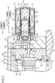
- FIG. 1 is a schematic side sectional view of main part of a compressed-fluid discharge control device 10 according to a first embodiment.
- the compressed-fluid discharge control device 10 includes a first housing 14 including a storage chamber 12 as an inner chamber, a second housing 18 accommodating a diaphragm valve 16, and a holder 22 holding a solenoid valve 20 serving as a pilot-chamber opening and closing valve configured to open and close a pilot chamber.
- the compressed-fluid discharge control device 10 is of a so-called stationary type in which the box-shaped first housing 14 is positioned and secured in place in a predetermined area at a worksite when the compressed-fluid discharge control device 10 is in use.
- the first housing 14 includes a hollow body portion 26 provided with a first supply channel 24 formed in a side part of the body portion 26.
- a regulating valve 30 is attached to the first supply channel 24, and an L-shaped pipe fitting 32 is connected to the regulating valve 30.
- the regulating valve 30 extends linearly in the longitudinal direction of the first housing 14, and a connecting part of the regulating valve 30 faces upward.
- a connection part of a vertical portion 34 constituting the L-shaped pipe fitting 32 is connected to the connecting part, while a supply pipe (not illustrated) is connected to a connection part of a horizontal portion 36 constituting the L-shaped pipe fitting 32.
- the supply pipe branches off from the regulating valve 30. Compressed air supplied from a compressed-air supply source (not illustrated) flows into the supply pipe.
- a flow control path 42 including an orifice 40 is formed inside the regulating valve 30.
- a needle 44 enters the orifice 40 in a retractable (withdrawable) manner.
- the flow control path 42 is closed when the needle 44 enters in the orifice 40, and the flow control path 42 is open when the needle 44 is withdrawn and retracted from the orifice 40.
- the body portion 26 includes an opening of a hollow interior formed in an upper part thereof.
- a cover portion 50 is disposed in the opening to close the hollow interior, whereby the storage chamber 12 is formed.
- the storage chamber 12 and the first supply channel 24 communicate with each other as a matter of course.
- the cover portion 50 and the body portion 26 are joined to each other by, for example, screws (not illustrated). In this case, the body portion 26 can be detached from the cover portion 50 by loosening the screws.
- the volume of the storage chamber 12 can be changed by replacing the body portion 26 with another body portion that, in cooperation with the cover portion 50, forms a storage chamber 12 having a hollow interior of a different volume.
- the gap between the cover portion 50 and the body portion 26 is sealed with a first seal member 52.
- the cover portion 50 includes a communication channel 54 formed in a thickness direction thereof.
- a tubular member 56 with a substantially T-shaped cross-section is fitted into the communication channel 54.
- the tubular member 56 has a communicating hole 58 with a narrower opening width than the communication channel 54.
- the gap between the tubular member 56 and the cover portion 50 is sealed with a second seal member 60.
- the second housing 18 includes a first holding member 62 and a second holding member 64 that hold the diaphragm valve 16 therebetween.
- the first holding member 62 is provided with a second supply channel 66 having an opening facing the communicating hole 58 and a valve chamber 68 connecting to the second supply channel 66 and circularly extending inside the second housing 18.
- the valve chamber 68 communicates with a discharge channel 70 extending in the longitudinal direction of the second housing 18. That is, the valve chamber 68 is disposed between the second supply channel 66 and the discharge channel 70 and communicates with both the channels 66 and 70.
- the discharge channel 70 has an opening facing the valve chamber 68, and the opening is provided with a ring-shaped first seat 72 protruding from the opening.
- the diaphragm valve 16 includes a thick valve element 74 having a substantially cylindrical shape and a flange portion 76 having a smaller thickness and a larger diameter than the valve element 74.
- the outer peripheral edge of the flange portion 76 is held between the first holding member 62 and the second holding member 64, and thereby the diaphragm valve 16 is held by the first holding member 62 and the second holding member 64.
- the valve element 74 has a short vertical hole 78 extending from a sidewall of the valve element 74 in a radial direction and a horizontal hole 80 connecting to the vertical hole 78 so as to be substantially orthogonal to the vertical hole 78 and extending toward the second holding member 64.
- the vertical hole 78 and the horizontal hole 80 connect the valve chamber 68 and a pilot chamber 82 (described below). That is, the vertical hole 78 and the horizontal hole 80 constitute a first pilot path for introducing compressed air into the pilot chamber 82.
- the second holding member 64 has a recess formed in an end face thereof that faces the diaphragm valve 16.
- the recess and an end face of the diaphragm valve 16 facing the second holding member 64 form the pilot chamber 82.
- the pilot chamber 82 communicates with a second pilot path 84 extending linearly toward the holder 22.
- An end of the discharge channel 70 has a discharge port exposed to the atmosphere.
- a predetermined member such as a nozzle or a diffuser (not illustrated) may be attached to the discharge port.
- the discharge channel 70 has an outlet port of a pilot exit path 86 opened at a position upstream of the discharge port.
- the pilot exit path 86 bends or inclines and extends toward the holder 22.
- the holder 22 has a valve entrance path 90, a valve attachment port 92, and a valve exit path 94.
- the valve entrance path 90 extends from the exit opening of the second pilot path 84 to the valve attachment port 92.
- the valve exit path 94 extends from the valve attachment port 92 to an inlet port of the pilot exit path 86.
- the valve exit path 94 has an opening facing the valve attachment port 92, and a ring-shaped second seat 96 protrudes from the vicinity of the opening.
- the gap between the second holding member 64 and the holder 22 is sealed with a third seal member 98 and a fourth seal member 100.
- the solenoid valve 20 is attached to the valve attachment port 92.
- the valve attachment port 92 has a first edge part (not illustrated) on the inner circumferential wall.
- the solenoid valve 20 includes a tubular body 102 with a substantially T-shaped cross-section.
- the tubular body 102 includes a large diameter portion 104 having a second edge part (not illustrated) formed on the outer circumferential wall. The second edge part engages with the first edge part, and thereby the solenoid valve 20 is held by the holder 22.
- the valve attachment port 92 functions as a valve chamber of the solenoid valve 20.
- the solenoid valve 20 includes an electromagnetic coil 112 produced by winding wires around a bobbin 110, a fixed core 116 and a movable core 118 inserted into an insertion hole 114 of the bobbin 110, and a valve plug 120 held at a distal end of the movable core 118.
- the bobbin 110, the movable core 118, and the valve plug 120 are accommodated inside a casing 122.
- the casing 122 has an exposure hole 124 formed in the right closed surface, and a circular cylindrical portion 126 with a small diameter constituting the fixed core 116 is exposed through the exposure hole 124.
- the circular cylindrical portion 126 has a recessed groove 128 in the side surface.
- a C-shaped clip 130 is engaged into the recessed groove 128, whereby the fixed core 116 is positioned and secured in place inside the insertion hole 114.
- a hollow collar member 132 is inserted inside the insertion hole 114. Most part of the movable core 118 is inserted inside the collar member 132. A left part of the collar member 132 is exposed from the casing 122 and is bent such that the diameter of the collar member 132 increases.
- the collar member 132 includes, at a left end thereof, a flange portion 136 formed by causing a circumferential wall portion 134 of the collar member 132 to rise up.
- the large diameter portion 104 of the tubular body 102 is fitted into a space defined by the flange portion 136 and the circumferential wall portion 134.
- the gap between the collar member 132 and the holder 22 is sealed with a fifth seal member 138.
- the movable core 118 has an engagement hole 140 at the left end.
- the engagement hole 140 has, near an opening thereof, an inner catch portion 142 which protrudes radially inward so as to reduce the inner diameter of the engagement hole 140.
- a head portion of the valve plug 120 made of rubber is inserted into the engagement hole 140.
- the head portion has a truncated cone shape tapered such that the diameter increases toward the base, and a portion with the largest diameter is caught or hooked onto the inner catch portion 142. As a result, the valve plug 120 is prevented from dropping off the engagement hole 140.
- the head portion elastically contracts as being pressed radially. After being inserted into the engagement hole 140, the head portion returns to the original shape by the elasticity. In this manner, the portion of the head portion having the largest diameter is caught or hooked onto the inner catch portion 142.
- An outer catch portion 144 is formed in the vicinity of an outer circumference of the inner catch portion 142.
- a small-diameter end of a return spring 146 having a truncated cone appearance is in contact with the outer catch portion 144.
- a large-diameter end of the return spring 146 is in contact with a stepped portion of the collar member 132 formed by a difference in diameter.
- the return spring 146 elastically biases the movable core 118 toward the valve exit path 94.
- the solenoid valve 20 is provided with an energization terminal (not illustrated) that is electrically connected to a power source 152 via a lead wire 150. Electric current supplied from the power source 152 flows through the electromagnetic coil 112 via the lead wire 150 and the energization terminal.
- a control switch 156 that operates under the control of a control circuit 154 is disposed on the lead wire 150 at a point away from the solenoid valve 20.
- the compressed-fluid discharge control device 10 according to the first embodiment is basically configured as above. Next, the operational effects thereof will be described.
- Compressed air is sent from the compressed-air supply source to the first supply channel 24 via the supply pipe and the regulating valve 30 and then introduced from the first supply channel 24 into the storage chamber 12.
- the compressed air flows into the pilot chamber 82 through the second supply channel 66, the communication channel 54 (communicating hole 58), the valve chamber 68, and the vertical hole 78 and the horizontal hole 80 (first pilot path) created in the diaphragm valve 16.
- the compressed air is then introduced into the valve attachment port 92 through the second pilot path 84 and the valve entrance path 90.
- the compressed air is blocked from flowing further since the valve plug 120 is seated on the second seat 96.
- the diaphragm valve 16 is kept in a state in which the valve element 74 is seated on the first seat 72. That is, the diaphragm valve 16 is closed, and communication between the storage chamber 12 and the discharge channel 70 is thus blocked.
- an operator operates the control switch 156 via the control circuit 154.
- This causes the control switch 156 to be closed (turned on), and electric current is supplied from the power source 152 to the electromagnetic coil 112 through the lead wire 150 and the energization terminal. That is, the solenoid valve 20 is energized, and the fixed core 116 is magnetized.
- the resulting magnetic effect occurring in the fixed core 116 causes the movable core 118 to be attracted and displaced toward the fixed core 116 as illustrated in FIG. 3 .
- the valve plug 120 held at the left end of the movable core 118 is separated from the second seat 96. With this separation, the return spring 146 is compressed.
- valve entrance path 90 and the valve exit path 94 communicate with each other via the valve attachment port 92. Consequently, the pilot chamber 82 communicates with the discharge channel 70 via the second pilot path 84, the valve entrance path 90, the valve attachment port 92 (valve chamber of the solenoid valve 20), the valve exit path 94, and the pilot exit path 86. As a result, the compressed air inside the pilot chamber 82 flows into the discharge channel 70 and is discharged from the discharge port. In this manner, closing of the control switch 156 causes the pilot chamber 82 to be opened and thus causes the compressed air inside the pilot chamber 82 to be discharged.
- the internal pressure in the pilot chamber 82 becomes smaller than the internal pressure in the valve chamber 68.
- the diaphragm valve 16 is configured to open as the compressed air inside the pilot chamber 82 is discharged in this manner, resulting in a high response speed.
- the storage chamber 12 communicates with the discharge channel 70.
- the first supply channel 24 also communicates with the discharge channel 70.
- the storage chamber 12 is filled with a predetermined volume of compressed air in advance. In other words, a predetermined amount of compressed air is already stored in the storage chamber 12. Consequently, the compressed air inside the storage chamber 12 is introduced into the discharge channel 70 via the second supply channel 66 and the valve chamber 68, and joins with the compressed air sent from the pilot chamber 82 to the discharge channel 70 as described above. As a result, compressed air is discharged from the discharge port at a high flow rate all at once.
- an instantaneous high discharge pressure peak pressure
- the upper limit of the peak pressure can be set according to the uses of the device by replacing the body portion 26 forming the storage chamber 12 and thereby changing the volume of the storage chamber 12 as appropriate. That is, the compressed air is prevented from being discharged at a higher pressure than necessary.
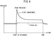
- the discharge pressure of a compressed-fluid discharge control device is indicated by a broken line. It is understood from FIG. 4 that the discharge pressure is substantially constant from the start to the end of discharge in the prior art and, by contrast, that the peak pressure can be obtained immediately after the start of discharge in the first embodiment. In this manner, in the first embodiment, the diaphragm valve 16 is opened by opening the pilot chamber 82, and in addition, the compressed air stored in the storage chamber 12 is discharged all at once. As a result, the peak pressure can be easily obtained by simply closing the control switch 156.
- control switch 156 can be closed in a different place from a worksite where blowing is performed, in other words, the solenoid valve 20 can be operated remotely.
- the solenoid valve 20 can be operated remotely.
- the pressure (discharge pressure) of the compressed air discharged from the discharge port at this moment is lower than the discharge pressure immediately after the start of discharge. That is, as illustrated in FIG. 4 , blowing continues at a constant low pressure.
- the discharge pressure at this moment can be adjusted according to the opening degree of the regulating valve 30. That is, the discharge pressure increases as the opening degree of the regulating valve 30 increases.
- the discharge pressure immediately after the start of discharge is set high (the peak pressure can be obtained) by discharging the compressed air stored in the storage chamber 12 first, and the subsequent discharge pressure is set low.
- static frictional force that acts on an object at rest is smaller than kinetic frictional force that acts on an object in motion. Consequently, even when the discharge pressure is changed as described above, it is possible to bring chips and dust and the like from a state of rest into a state of motion by the peak pressure immediately after the start of discharge, and keep the chips and dust in a state of motion by the subsequent low discharge pressure. As a result, the chips and dust can be easily removed.
- compressed air only needs to be discharged at a high flow rate in a very short time, in order to increase the discharge pressure. That is, compressed air does not need to be continuously discharged at a high flow rate. This results in a reduction in the consumption of compressed air and thus leads to energy savings.
- compressed air retained in the pilot chamber 82, the second pilot path 84, and the valve entrance path 90 is used for blowing as described above. This further increases the peak pressure immediately after the start of discharge while reducing the consumption of compressed air to thereby save more energy.
- the solenoid valve 20 is closed and communication between the pilot chamber 82 and the discharge channel 70 is blocked. Meanwhile, compressed air is supplied from the valve chamber 68 to the pilot chamber 82 via the vertical hole 78 and the horizontal hole 80. This increases the internal pressure in the pilot chamber 82 compared with the internal pressure in the valve chamber 68 and thus causes the valve element 74 of the diaphragm valve 16 to be seated on the first seat 72. That is, the diaphragm valve 16 is closed, so that the communication between the storage chamber 12 and the discharge channel 70 and the communication between the valve chamber 68 and the discharge channel 70 are blocked.
- the holder 22 and the solenoid valve 20 may be disposed away from the second holding member 64.
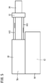
- a pipe 160 for drawing air into the valve may be disposed between the second pilot path 84 and the valve entrance path 90, and a pipe 162 for drawing air out of the valve may be disposed between the valve exit path 94 and the pilot exit path 86.
- the solenoid valve 20 can be disposed in a position away from a worksite where, for example, water sprays all over. This prevents the solenoid valve 20 from getting wet.
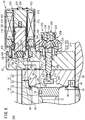
- a compressed-fluid discharge control device 200 according to the second embodiment illustrated in FIG. 6 includes a flow control unit 202 serving as an example of a displacement limiting unit.
- the flow control unit 202 basically has a structure similar to that described in Japanese Patent No. 6179510 , only an outline thereof will be described.
- the flow control unit 202 includes a flow adjustment section 204, a displaceable member 206, and a stopper 208 serving as a contact member.
- the displaceable member 206 is inserted into a screw hole 210 formed in the holder 22 and an insertion hole 212 formed in the second holding member 64.
- a left end part of the displaceable member 206 protrudes into the pilot chamber 82.
- the stopper 208 is attached to the left end part of the displaceable member 206.
- the flow adjustment section 204 also functions as an operating mechanism for adjusting the protruding length of the displaceable member 206 inside the pilot chamber 82 and thereby limiting the displacement of the valve element 74, in other words, the opening degree of the diaphragm valve 16.
- the flow adjustment section 204 includes a housing 214 accommodating the operating mechanism, and a knob 216 rotatably attached to the housing 214.
- the housing 214 is detachably attached to the second holding member 64.
- the housing 214 is dividable into a first case 218 and a second case 220.
- the second case 220 has a dome shape to have an interior space with a predetermined volume when mounted on the first case 218.
- the second case 220 has an opening with a relatively large inner diameter at an end part thereof facing the first case 218, and a right end part of the first case 218 is inserted into the opening.
- a plurality of (for example, four) locking holes are formed in the side surface of the second case 220 at regular intervals.
- Mounting hooks 222 protruding from the side surface of the first case 218 are inserted into the locking holes.
- the first case 218 and the second case 220 are connected to each other by the insertion of the mounting hooks 222 into the locking holes.
- the knob 216 functions as an operating portion that adjusts the flow rate of fluid inside the compressed-fluid discharge control device 200 by being rotated relative to the housing 214 by the operator. That is, the knob 216 has a tubular shape having a bottom on the right and includes a tubular fitting part 224 extending leftward from the center of the bottom inside the tube. The fitting part 224 is fitted on a rotation transmitting member 226. The inner circumferential surface (female type) of the fitting part 224 and the outer circumferential surface (male type) of the rotation transmitting member 226 are fitted with each other such that the knob 216 is displaceable in the left and right direction. Thus, the rotational force of the knob 216 is transmitted smoothly to the rotation transmitting member 226.
- the rotation transmitting member 226 controls the displacements of the displaceable member 206 and the stopper 208 and has a predetermined length.
- the rotation transmitting member 226 includes a tubular part 228 having a hollow cylindrical shape and a post part 230 extending leftward from an end face of the tubular part 228.
- the tubular part 228 has a hollow interior formed as a space inside which a shaft portion 232 of the displaceable member 206 is movable back and forth in the axial direction.
- the tubular part 228 includes an internal thread part formed in the inner circumferential wall, and an external thread part formed on the circumferential sidewall of the shaft portion 232 of the displaceable member 206 is screw-engaged into the internal thread part and the screw hole 210.
- the post part 230 has a circular cylindrical shape with an outer diameter smaller than that of the tubular part 228 and extends rightward through the housing 214. A right end part of the post part 230 is connected to the knob 216.
- the displaceable member 206 is a solid round-rod member extending in the left and right direction.
- the displaceable member 206 includes a connection end portion 233 and the shaft portion 232.
- the stopper 208 is disposed on the end face of the connection end portion 233 and can be brought into contact with the end face of the valve element 74.
- the shaft portion 232 has a predetermined length along the axial direction and includes the external thread part formed on the sidewall as described above.
- the external thread part is screw-engaged into the internal thread part formed in the inner surface of the rotation transmitting member 226 extending toward the shaft portion 232.
- the displaceable member 206 including the shaft portion 232 can be moved back and forth (displaced) in the left and right direction.
- the flow adjustment section 204 includes an indicator ring 234 disposed inside the housing 214.
- the indicator ring 234 is rotatably housed inside the dome-shaped second case 220.
- the second case 220 includes a display window (not illustrated) in the side surface, and graduations on the indicator ring 234 are visible through the display window.
- the second case 220 includes a tubular protruding part 238 having a predetermined inner diameter.
- the protruding part 238 is inserted into the knob 216 and rotatably supports the knob 216.
- a knob-rotation limiting part 240 is disposed on a left end part of the outer circumferential surface of the protruding part 238.
- a first annular protrusion 242 and a second annular protrusion 244 are formed on the left of the knob-rotation limiting part 240.
- An inner protruding part 245 at a right end part of the knob 216 can engage with the first annular protrusion 242 and the second annular protrusion 244 in a stepwise manner.
- a plurality of ridges are formed on the outer circumferential surface of a wall of the knob 216 enclosing the fitting part 224 so that the operator can grip the knob 216 easily.
- a contact part 246 brought into contact with the knob-rotation limiting part 240 is disposed on a right end of the inner circumferential surface of the wall.
- the inner protruding part 245 protruding radially inward is disposed on a left end of the inner circumferential surface of the wall.
- the knob 216 can be switched between a rotatable state and a non-rotatable state according to the position in the left and right direction relative to the protruding part 238. That is, when the knob 216 is disposed in a left position where the inner protruding part 245 is caught by the second annular protrusion 244 on the protruding part 238, the contact part 246 of the knob 216 is in contact with the knob-rotation limiting part 240, and thus the rotation of the knob 216 is restricted. To rotate the knob 216, the knob 216 is moved to the right to get over the second annular protrusion 244, so that the contact part 246 is separated from the knob-rotation limiting part 240. This allows the knob 216 to rotate relative to the second case 220.
- the post part 230 of the rotation transmitting member 226 is inserted into a hole part 248 of the indicator ring 234 in a state where the indicator ring 234 is disposed in place.
- the indicator ring 234 includes an internal-contact tooth part (not illustrated), and the rotation transmitting member 226 includes a pair of meshing parts (not illustrated) on the outer circumferential surface. The indicator ring 234 is rotated only when the meshing parts engage (mesh) with the internal-contact tooth part.
- the operator grips the knob 216 and moves the knob 216 to the right. This causes the inner protruding part 245 at the left end of the knob 216 to engage with the first annular protrusion 242, and at the same time, the meshing parts becomes engaged with the internal-contact tooth part.
- the operator then rotates the knob 216 to thereby rotate the rotation transmitting member 226 and the indicator ring 234.
- the displaceable member 206 moves to the left or right inside the hollow interior of the tubular part 228 while rotating.
- the stopper 208 moves to the left or right inside the pilot chamber 82.
- the position of the stopper 208 can be acquired from the graduations on the indicator ring 234. That is, for example, in a case where the flow rate of pressurized fluid inside the compressed-fluid discharge control device 200 needs to be increased according to the numbers of the graduations, the displaceable member 206 and the stopper 208 may be set to move to the right as the numbers of the graduations become larger.
- the stopper 208 serving as the contact member is positioned and secured in place by the above locking action.
- the maximum opening degree of the diaphragm valve 16 is kept constant, and the flow rate of compressed air when the diaphragm valve 16 is open at the maximum opening degree becomes stable.
- the operator becomes unable to adjust the opening degree easily, and thus it is possible to prevent, for example, discharge of more than the required amount set by a manager in advance.
- the diaphragm valve 16 is kept closed since the internal pressure produced by the compressed air inside the valve chamber 68 and the internal pressure produced by the compressed air inside the pilot chamber 82 are balanced. Thus, the communication between the storage chamber 12 and the discharge channel 70 is blocked.
- the operator When the operator performs cleaning or the like by blowing air, the operator operates the control switch 156 via the control circuit 154 as in the first embodiment. This causes the control switch 156 to be closed (turned on), and an electric current is supplied from the power source 152 to the electromagnetic coil 112 through the lead wire 150 and the energization terminal.
- the fixed core 116 is magnetized, and thus a magnetic effect occurs.
- the movable core 118 is attracted and displaced toward the fixed core 116, and the valve plug 120 held at the left end of the movable core 118 is separated from the second seat 96. With this separation, the return spring 146 is compressed.
- valve entrance path 90 and the valve exit path 94 communicate with each other via the valve attachment port 92 (valve chamber of the solenoid valve 20). Consequently, the pilot chamber 82 communicates with the discharge channel 70 via the second pilot path 84, the valve entrance path 90, the valve attachment port 92, the valve exit path 94, and the pilot exit path 86. As a result, the compressed air inside the pilot chamber 82 flows into the discharge channel 70 and is discharged from the discharge port. In this manner, closing of the control switch 156 causes the pilot chamber 82 to be opened and thus causes the compressed air inside the pilot chamber 82 to be discharged.
- the displacement of the valve element 74 in a direction away from the first seat 72 stops when the end face of the valve element 74 comes into contact with the stopper 208. That is, further displacement of the valve element 74 is stopped by the stopper 208.
- the compressed air flowing from the interior of the storage chamber 12 and the compressed air sent out from the pilot chamber 82 are discharged out of the discharge channel 70 at a flow rate corresponding to the opening degree.
- the positions of the displaceable member 206 and the stopper 208 are changed by rotating the knob 216.
- the protruding length of the stopper 208 into the pilot chamber 82 increases, the displacement of the valve element 74 decreases, and thus the opening degree of the diaphragm valve 16 decreases.
- the flow rate of compressed air that is, the amount of discharge decreases.
- the protruding length of the stopper 208 decreases, the displacement of the valve element 74 and the opening degree of the diaphragm valve 16 increase, and the flow rate of compressed air, that is, the amount of discharge increases.
- the position where the stopper 208 comes into contact with the valve element 74 determines the opening degree of the diaphragm valve 16 and, as a result, the discharge amount of compressed air is determined. That is, the flow control unit 202 limits the maximum flow rate and the peak pressure of compressed air.
- the protruding length of the stopper 208 can be finely changed by rotating the knob 216. Consequently, the maximum flow rate of compressed air discharged from the discharge channel 70 can be finely changed. That is, the discharge amount of compressed air and the peak pressure can be precisely limited. This prevents discharge of more than the required amount from the compressed-fluid discharge control device 200. Moreover, reducing the displacement, in other words, the stroke, of the diaphragm valve 16 further increases the response speed.
- the volume of the storage chamber 12 can be changed as appropriate by replacing the body portion 26 constituting the first housing 14. This allows the upper limit of the peak pressure to be set according to the uses of the device and thus prevents compressed air from being discharged at a higher pressure than necessary.
- the second embodiment also produces operational effects similar to those of the first embodiment as a matter of course.
- compressed fluid such as compressed nitrogen may be used instead of compressed air.
- compressed-fluid discharge control device 10 is not limited in particular to the stationary type and may have other shapes including a gun shape.
Landscapes
- Engineering & Computer Science (AREA)
- General Engineering & Computer Science (AREA)
- Mechanical Engineering (AREA)
- Physics & Mathematics (AREA)
- Fluid Mechanics (AREA)
- Fluid-Driven Valves (AREA)
- Nozzles (AREA)
- Reciprocating Pumps (AREA)
Abstract
Description
- The present invention relates to compressed-fluid discharge control devices that control discharge of compressed fluid.
- In machining, cutting powder or chip powder of metal produced during cutting process adheres to surfaces of workpieces. In order to remove such powder and clean the surfaces of the workpieces, blasting compressed fluid (mainly compressed air) is widely performed. Compressed-fluid discharge control devices used for performing such blasting (blowing) include, for example, gun-shaped tools disclosed in
Japanese Laid-Open Patent Publication Nos. 2005-246356 2014-083518 - This type of air blow gun includes a housing including a handle gripped by an operator and a lever rotatably attached to the housing. When the operator pushes the lever toward the handle using their fingers, an opening and closing valve disposed between a supply channel and a discharge channel formed inside the handle opens, and thereby the supply channel and the discharge channel communicate with each other. This causes compressed air supplied from a compressed-air supply source to the supply channel to flow into the discharge channel and then to be discharged from an opening (discharge port) in the discharge channel.
- As described above, the operator needs to grip the lever to perform blast of air using the air blow gun. That is, the operator needs to operate the air blow gun at a worksite where blast of air is performed. Thus, in a case where the operator needs to operate the air blow gun in a place where, for example, water sprays all over, the operator disadvantageously gets wet.
- A principal object of the present invention is to provide a compressed-fluid discharge control device capable of being opened and closed electrically without manual opening and closing operation directly performed by an operator.
- Another object of the present invention is to provide a compressed-fluid discharge control device also capable of being opened and closed remotely.
- According to an aspect of the present invention, a compressed-fluid discharge control device configured to control discharge of compressed fluid includes
a valve chamber provided with a seat and configured to communicate with a supply channel through which the compressed fluid is supplied and a discharge channel having a discharge port through which the compressed fluid is discharged,
a diaphragm valve including a pilot path and configured to block communication between the supply channel and the discharge channel by being seated on the seat and to establish the communication by being separated from the seat, and
a pilot-chamber opening and closing valve configured to open and close a pilot chamber into which the compressed fluid is introduced from the supply channel via the pilot path, wherein
the pilot-chamber opening and closing valve includes a solenoid valve configured to be opened when energized and to be closed when de-energized, and
when the pilot-chamber opening and closing valve is opened to open the pilot chamber, the diaphragm valve is separated from the seat, and thereby the supply channel and the discharge channel communicate with each other. - In the present invention, a solenoid valve is used as the pilot-chamber opening and closing valve for opening and closing the pilot chamber to open and close the diaphragm valve. The diaphragm valve can be opened by energizing the solenoid valve to open the pilot chamber and can be closed by de-energizing the solenoid valve to close the pilot chamber. That is, an operator does not need to perform opening and closing operation at a worksite. Thus, even in a case where water sprays all over the worksite, the operator is prevented from getting wet.
- Moreover, this structure enables a control switch for opening and closing the solenoid valve to be disposed in a place away from the solenoid valve. In this case, the solenoid valve and the diaphragm valve can be opened and closed remotely, thereby preventing the operator from getting wet by water spray and the like more reliably.
- In addition, in this structure, compressed fluid that has reached a valve chamber flows into the discharge channel all at once and is discharged from an open end (discharge port) of the discharge channel. Thus, an instantaneous high discharge pressure (peak pressure) can be obtained immediately after the start of discharge. Such instantaneous discharge of compressed fluid at a high discharge pressure can easily bring, for example, objects at rest into a state of motion. This improves the efficiency in removing chips, dust, and other particles. Moreover, the peak pressure can be obtained without discharging a large amount of compressed fluid. This results in a reduction in the consumption of compressed fluid and thus leads to energy savings.
- It is preferable that a storage chamber configured to store compressed fluid be disposed between the supply channel and the valve chamber. In this case, compressed fluid that has been stored in the storage chamber in advance flows into the discharge channel all at once as the diaphragm valve opens. As a result, even higher discharge pressure can be easily obtained. As a matter of course, the efficiency in removing the chips, dust, and other particles is further improved in this case.
- In the case where the storage chamber is provided, the storage chamber may be configured as a variable-volume inner chamber of which volume can be changed. This enables the upper limit of the discharge pressure (peak pressure) of compressed fluid to be set according to the uses of the device.
- Moreover, in the case where the storage chamber is provided, it is preferable that a regulating valve configured to adjust the flow rate of compressed fluid introduced from the supply channel into the storage chamber be provided. In this case, for example, the flow rate of the compressed fluid introduced into the storage chamber can be set small by reducing the opening degree of the regulating valve. In a case where the diaphragm valve is still open after the discharge at the high discharge pressure ends, compressed fluid passes through the storage chamber, reaches the discharge channel, and is discharged at a low pressure. That is, blowing at a low pressure can be continued.
- In general, kinetic frictional force that acts on an object in motion is smaller than static frictional force that acts on an object at rest. Consequently, once chips and dust are subjected to a high discharge pressure and brought into a state of motion, the chips and dust can be maintained in the state of motion even with a low discharge pressure. As a result, removal of such foreign substances can be continued.
- Furthermore, it is preferable that the pilot-chamber opening and closing valve be configured to establish and block communication between the pilot chamber and the discharge channel. In this case, when the pilot chamber is opened, the compressed fluid inside the pilot chamber flows into the discharge channel. That is, the compressed fluid inside the pilot chamber can also be discharged and used to remove the dust and the like. This results in a further increase in the peak pressure immediately after the start of discharge and, in addition, leads to more energy savings.
- Reducing the stroke of the diaphragm valve further increases the response speed. That is, the peak pressure can be obtained immediately after the operator operates an operating member for opening and closing. To achieve this, it is preferable that a contact member displaceable relative to a valve element of the diaphragm valve be provided to limit the displacement of the valve element by coming into contact with the valve element. That is, a displacement limiting unit may be provided.
- In this case, further displacement of the valve element is stopped by the contact of the contact member with the valve element. The opening degree at a point in time when the displacement is stopped is defined as the maximum opening degree of the diaphragm valve. In this manner, the maximum opening degree of the diaphragm valve can be made smaller than the designed maximum opening when the contact member is not brought into contact with the valve element. As a result of this, the flow rate of the pressurized fluid discharged from the diaphragm valve is reduced compared with the designed flow rate. Consequently, pressurized fluid of more than the required amount is prevented from being discharged.
- Moreover, the stop position of the valve element can be changed by changing the position of the contact member. That is, the maximum opening degree of the diaphragm valve can be changed to any desired value. The maximum opening degree of the diaphragm valve and thus the flow rate and the peak pressure of the pressurized fluid flowing from the diaphragm valve can be precisely regulated by precisely adjusting the position of the contact member.
- The pilot-chamber opening and closing valve (solenoid valve) can also be disposed in a place away from a worksite. To do so, the pilot chamber and the discharge channel may communicate with a valve chamber of the pilot-chamber opening and closing valve via a pipe. The pilot-chamber opening and closing valve can be disposed away from the worksite by the length of the pipe. Consequently, even in a case where water sprays all over the worksite, the pilot-chamber opening and closing valve is prevented from getting wet.
- According to the present invention, the solenoid valve configured to be opened when energized and to be closed when de-energized is used as the pilot-chamber opening and closing valve that opens and closes the pilot chamber. This configuration enables the solenoid valve to be opened and closed electrically. That is, the pilot-chamber opening and closing valve can be opened and closed without operator's manual operations performed at the worksite. Consequently, the operator is prevented from getting wet.
- In addition, the diaphragm valve is opened and closed as the pilot chamber is opened and closed. When the diaphragm valve is opened, compressed fluid that has reached the valve chamber flows into the discharge channel all at once and is discharged from the discharge port. As a result, regardless of the operating speed of the operating member for opening and closing, an instantaneous high discharge pressure (peak pressure) can be obtained immediately after the start of discharge. Consequently, a high discharge pressure can be obtained without discharging a large amount of compressed fluid. This results in a reduction in the consumption of compressed fluid and thus leads to energy savings.
- A large force acts on, for example, objects at rest by instantaneously discharging compressed fluid at a high discharge pressure. As a result, the objects are easily brought into a state of motion. In a case where the objects correspond to, for example, chips and dust, the efficiency in removing such foreign substances is improved.
-
-
FIG. 1 is a schematic longitudinal sectional view of main part of a compressed-fluid discharge control device according to a first embodiment of the present invention; -
FIG. 2 is an enlarged cross-sectional view of main part of the compressed-fluid discharge control device inFIG. 1 ; -
FIG. 3 is an enlarged cross-sectional view of main part when a solenoid valve and a diaphragm valve constituting the compressed-fluid discharge control device inFIG. 1 are open; -
FIG. 4 is a graph illustrating changes in discharge pressure over time; -
FIG. 5 is a schematic view of a structure of the compressed-fluid discharge control device in which the solenoid valve is disposed away from a second housing via pipes; -
FIG. 6 is an enlarged cross-sectional view of main part of a compressed-fluid discharge control device according to a second embodiment of the present invention; -
FIG. 7 is a partially enlarged cross-sectional view of the compressed-fluid discharge control device inFIG. 6 ; and -
FIG. 8 is an enlarged cross-sectional view of main part when a solenoid valve and a diaphragm valve constituting the compressed-fluid discharge control device inFIG. 6 are open. - Preferred embodiments of a compressed-fluid discharge control device according to the present invention will be described in detail below with reference to the accompanying drawings. In the examples below, compressed air is used as compressed fluid. In the below, terms such as "left", "right", and "up" indicate respectively the left side, the right side, the lower side, and the upper side in
FIGS. 1 to 3 andFIGS. 5 to 8 . However, these terms are used for convenience to facilitate understanding and do not limit the position of the compressed-fluid discharge control device in practical use. -
FIG. 1 is a schematic side sectional view of main part of a compressed-fluiddischarge control device 10 according to a first embodiment. The compressed-fluiddischarge control device 10 includes afirst housing 14 including astorage chamber 12 as an inner chamber, asecond housing 18 accommodating adiaphragm valve 16, and aholder 22 holding asolenoid valve 20 serving as a pilot-chamber opening and closing valve configured to open and close a pilot chamber. The compressed-fluiddischarge control device 10 is of a so-called stationary type in which the box-shapedfirst housing 14 is positioned and secured in place in a predetermined area at a worksite when the compressed-fluiddischarge control device 10 is in use. - The
first housing 14 includes ahollow body portion 26 provided with afirst supply channel 24 formed in a side part of thebody portion 26. A regulatingvalve 30 is attached to thefirst supply channel 24, and an L-shaped pipe fitting 32 is connected to the regulatingvalve 30. The regulatingvalve 30 extends linearly in the longitudinal direction of thefirst housing 14, and a connecting part of the regulatingvalve 30 faces upward. A connection part of avertical portion 34 constituting the L-shaped pipe fitting 32 is connected to the connecting part, while a supply pipe (not illustrated) is connected to a connection part of ahorizontal portion 36 constituting the L-shaped pipe fitting 32. As a result, in an exterior view thereof, the supply pipe branches off from the regulatingvalve 30. Compressed air supplied from a compressed-air supply source (not illustrated) flows into the supply pipe. - A
flow control path 42 including anorifice 40 is formed inside the regulatingvalve 30. Aneedle 44 enters theorifice 40 in a retractable (withdrawable) manner. Theflow control path 42 is closed when theneedle 44 enters in theorifice 40, and theflow control path 42 is open when theneedle 44 is withdrawn and retracted from theorifice 40. - The
body portion 26 includes an opening of a hollow interior formed in an upper part thereof. Acover portion 50 is disposed in the opening to close the hollow interior, whereby thestorage chamber 12 is formed. Thestorage chamber 12 and thefirst supply channel 24 communicate with each other as a matter of course. Thecover portion 50 and thebody portion 26 are joined to each other by, for example, screws (not illustrated). In this case, thebody portion 26 can be detached from thecover portion 50 by loosening the screws. The volume of thestorage chamber 12 can be changed by replacing thebody portion 26 with another body portion that, in cooperation with thecover portion 50, forms astorage chamber 12 having a hollow interior of a different volume. The gap between thecover portion 50 and thebody portion 26 is sealed with afirst seal member 52. - The
cover portion 50 includes acommunication channel 54 formed in a thickness direction thereof. Atubular member 56 with a substantially T-shaped cross-section is fitted into thecommunication channel 54. Thetubular member 56 has a communicatinghole 58 with a narrower opening width than thecommunication channel 54. The gap between thetubular member 56 and thecover portion 50 is sealed with asecond seal member 60. - The
second housing 18 includes a first holdingmember 62 and a second holdingmember 64 that hold thediaphragm valve 16 therebetween. The first holdingmember 62 is provided with asecond supply channel 66 having an opening facing the communicatinghole 58 and avalve chamber 68 connecting to thesecond supply channel 66 and circularly extending inside thesecond housing 18. Thevalve chamber 68 communicates with adischarge channel 70 extending in the longitudinal direction of thesecond housing 18. That is, thevalve chamber 68 is disposed between thesecond supply channel 66 and thedischarge channel 70 and communicates with both thechannels discharge channel 70 has an opening facing thevalve chamber 68, and the opening is provided with a ring-shapedfirst seat 72 protruding from the opening. - The
diaphragm valve 16 includes athick valve element 74 having a substantially cylindrical shape and aflange portion 76 having a smaller thickness and a larger diameter than thevalve element 74. The outer peripheral edge of theflange portion 76 is held between the first holdingmember 62 and the second holdingmember 64, and thereby thediaphragm valve 16 is held by the first holdingmember 62 and the second holdingmember 64. - The
valve element 74 has a shortvertical hole 78 extending from a sidewall of thevalve element 74 in a radial direction and ahorizontal hole 80 connecting to thevertical hole 78 so as to be substantially orthogonal to thevertical hole 78 and extending toward the second holdingmember 64. Thevertical hole 78 and thehorizontal hole 80 connect thevalve chamber 68 and a pilot chamber 82 (described below). That is, thevertical hole 78 and thehorizontal hole 80 constitute a first pilot path for introducing compressed air into thepilot chamber 82. - The second holding
member 64 has a recess formed in an end face thereof that faces thediaphragm valve 16. The recess and an end face of thediaphragm valve 16 facing the second holdingmember 64 form thepilot chamber 82. Thepilot chamber 82 communicates with asecond pilot path 84 extending linearly toward theholder 22. - An end of the
discharge channel 70 has a discharge port exposed to the atmosphere. A predetermined member such as a nozzle or a diffuser (not illustrated) may be attached to the discharge port. Thedischarge channel 70 has an outlet port of apilot exit path 86 opened at a position upstream of the discharge port. Thepilot exit path 86 bends or inclines and extends toward theholder 22. - The
holder 22 has avalve entrance path 90, avalve attachment port 92, and avalve exit path 94. Thevalve entrance path 90 extends from the exit opening of thesecond pilot path 84 to thevalve attachment port 92. Thevalve exit path 94 extends from thevalve attachment port 92 to an inlet port of thepilot exit path 86. Thevalve exit path 94 has an opening facing thevalve attachment port 92, and a ring-shapedsecond seat 96 protrudes from the vicinity of the opening. The gap between the second holdingmember 64 and theholder 22 is sealed with athird seal member 98 and afourth seal member 100. - The
solenoid valve 20 is attached to thevalve attachment port 92. Specifically, thevalve attachment port 92 has a first edge part (not illustrated) on the inner circumferential wall. Thesolenoid valve 20 includes atubular body 102 with a substantially T-shaped cross-section. Thetubular body 102 includes alarge diameter portion 104 having a second edge part (not illustrated) formed on the outer circumferential wall. The second edge part engages with the first edge part, and thereby thesolenoid valve 20 is held by theholder 22. Thevalve attachment port 92 functions as a valve chamber of thesolenoid valve 20. - As illustrated in
FIG. 2 in detail, thesolenoid valve 20 includes anelectromagnetic coil 112 produced by winding wires around abobbin 110, a fixedcore 116 and amovable core 118 inserted into aninsertion hole 114 of thebobbin 110, and avalve plug 120 held at a distal end of themovable core 118. Thebobbin 110, themovable core 118, and thevalve plug 120 are accommodated inside acasing 122. - The
casing 122 has anexposure hole 124 formed in the right closed surface, and a circularcylindrical portion 126 with a small diameter constituting the fixedcore 116 is exposed through theexposure hole 124. The circularcylindrical portion 126 has a recessedgroove 128 in the side surface. A C-shapedclip 130 is engaged into the recessedgroove 128, whereby the fixedcore 116 is positioned and secured in place inside theinsertion hole 114. - Most part of a
hollow collar member 132 is inserted inside theinsertion hole 114. Most part of themovable core 118 is inserted inside thecollar member 132. A left part of thecollar member 132 is exposed from thecasing 122 and is bent such that the diameter of thecollar member 132 increases. Thecollar member 132 includes, at a left end thereof, aflange portion 136 formed by causing acircumferential wall portion 134 of thecollar member 132 to rise up. Thelarge diameter portion 104 of thetubular body 102 is fitted into a space defined by theflange portion 136 and thecircumferential wall portion 134. The gap between thecollar member 132 and theholder 22 is sealed with afifth seal member 138. - The
movable core 118 has anengagement hole 140 at the left end. Theengagement hole 140 has, near an opening thereof, aninner catch portion 142 which protrudes radially inward so as to reduce the inner diameter of theengagement hole 140. A head portion of thevalve plug 120 made of rubber is inserted into theengagement hole 140. The head portion has a truncated cone shape tapered such that the diameter increases toward the base, and a portion with the largest diameter is caught or hooked onto theinner catch portion 142. As a result, thevalve plug 120 is prevented from dropping off theengagement hole 140. When the head portion is inserted into theengagement hole 140, the head portion elastically contracts as being pressed radially. After being inserted into theengagement hole 140, the head portion returns to the original shape by the elasticity. In this manner, the portion of the head portion having the largest diameter is caught or hooked onto theinner catch portion 142. - An
outer catch portion 144 is formed in the vicinity of an outer circumference of theinner catch portion 142. A small-diameter end of areturn spring 146 having a truncated cone appearance is in contact with theouter catch portion 144. A large-diameter end of thereturn spring 146 is in contact with a stepped portion of thecollar member 132 formed by a difference in diameter. Thereturn spring 146 elastically biases themovable core 118 toward thevalve exit path 94. As a result, when thesolenoid valve 20 is not energized, the circular cylindrical portion of thevalve plug 120 having a constant diameter is seated on thesecond seat 96, to thereby maintain a closed state. - The
solenoid valve 20 is provided with an energization terminal (not illustrated) that is electrically connected to apower source 152 via alead wire 150. Electric current supplied from thepower source 152 flows through theelectromagnetic coil 112 via thelead wire 150 and the energization terminal. Acontrol switch 156 that operates under the control of acontrol circuit 154 is disposed on thelead wire 150 at a point away from thesolenoid valve 20. - The compressed-fluid
discharge control device 10 according to the first embodiment is basically configured as above. Next, the operational effects thereof will be described. - Compressed air is sent from the compressed-air supply source to the
first supply channel 24 via the supply pipe and the regulatingvalve 30 and then introduced from thefirst supply channel 24 into thestorage chamber 12. When thestorage chamber 12 is filled with compressed air, the compressed air flows into thepilot chamber 82 through thesecond supply channel 66, the communication channel 54 (communicating hole 58), thevalve chamber 68, and thevertical hole 78 and the horizontal hole 80 (first pilot path) created in thediaphragm valve 16. The compressed air is then introduced into thevalve attachment port 92 through thesecond pilot path 84 and thevalve entrance path 90. The compressed air is blocked from flowing further since thevalve plug 120 is seated on thesecond seat 96. - In this state, the internal pressure produced by the compressed air inside the
valve chamber 68 and the internal pressure produced by the compressed air inside thepilot chamber 82 are balanced. Thus, thediaphragm valve 16 is kept in a state in which thevalve element 74 is seated on thefirst seat 72. That is, thediaphragm valve 16 is closed, and communication between thestorage chamber 12 and thedischarge channel 70 is thus blocked. - To perform cleaning or the like by blowing air, an operator operates the
control switch 156 via thecontrol circuit 154. This causes thecontrol switch 156 to be closed (turned on), and electric current is supplied from thepower source 152 to theelectromagnetic coil 112 through thelead wire 150 and the energization terminal. That is, thesolenoid valve 20 is energized, and the fixedcore 116 is magnetized. The resulting magnetic effect occurring in the fixedcore 116 causes themovable core 118 to be attracted and displaced toward the fixedcore 116 as illustrated inFIG. 3 . As a result, thevalve plug 120 held at the left end of themovable core 118 is separated from thesecond seat 96. With this separation, thereturn spring 146 is compressed. - As the
valve plug 120 is separated from thesecond seat 96, thevalve entrance path 90 and thevalve exit path 94 communicate with each other via thevalve attachment port 92. Consequently, thepilot chamber 82 communicates with thedischarge channel 70 via thesecond pilot path 84, thevalve entrance path 90, the valve attachment port 92 (valve chamber of the solenoid valve 20), thevalve exit path 94, and thepilot exit path 86. As a result, the compressed air inside thepilot chamber 82 flows into thedischarge channel 70 and is discharged from the discharge port. In this manner, closing of thecontrol switch 156 causes thepilot chamber 82 to be opened and thus causes the compressed air inside thepilot chamber 82 to be discharged. - Due to the above discharge, the internal pressure in the
pilot chamber 82 becomes smaller than the internal pressure in thevalve chamber 68. This causes thevalve element 74 of thediaphragm valve 16 to be pushed by the compressed air inside thevalve chamber 68 and, as a result, thevalve element 74 is separated from thefirst seat 72 immediately. That is, thediaphragm valve 16 opens immediately. Thediaphragm valve 16 is configured to open as the compressed air inside thepilot chamber 82 is discharged in this manner, resulting in a high response speed. - As the
diaphragm valve 16 opens, thestorage chamber 12 communicates with thedischarge channel 70. In a case where theflow control path 42 is not fully closed by theneedle 44 of the regulating valve 30 (seeFIG. 1 ), thefirst supply channel 24 also communicates with thedischarge channel 70. - The
storage chamber 12 is filled with a predetermined volume of compressed air in advance. In other words, a predetermined amount of compressed air is already stored in thestorage chamber 12. Consequently, the compressed air inside thestorage chamber 12 is introduced into thedischarge channel 70 via thesecond supply channel 66 and thevalve chamber 68, and joins with the compressed air sent from thepilot chamber 82 to thedischarge channel 70 as described above. As a result, compressed air is discharged from the discharge port at a high flow rate all at once. Thus, as indicated by a solid line inFIG. 4 , an instantaneous high discharge pressure (peak pressure) can be obtained immediately after the start of discharge (blowing). The upper limit of the peak pressure can be set according to the uses of the device by replacing thebody portion 26 forming thestorage chamber 12 and thereby changing the volume of thestorage chamber 12 as appropriate. That is, the compressed air is prevented from being discharged at a higher pressure than necessary. - In
FIG. 4 , the discharge pressure of a compressed-fluid discharge control device according to a prior art is indicated by a broken line. It is understood fromFIG. 4 that the discharge pressure is substantially constant from the start to the end of discharge in the prior art and, by contrast, that the peak pressure can be obtained immediately after the start of discharge in the first embodiment. In this manner, in the first embodiment, thediaphragm valve 16 is opened by opening thepilot chamber 82, and in addition, the compressed air stored in thestorage chamber 12 is discharged all at once. As a result, the peak pressure can be easily obtained by simply closing thecontrol switch 156. - In addition, by arranging the
control circuit 154 at a position away from a place where the blowing is performed, thecontrol switch 156 can be closed in a different place from a worksite where blowing is performed, in other words, thesolenoid valve 20 can be operated remotely. Thus, even in a case where water sprays all over the worksite, the operator is prevented from getting wet. - When the
flow control path 42 is fully closed by theneedle 44 of the regulatingvalve 30, communication between thefirst supply channel 24 and thestorage chamber 12 is blocked. Consequently, even when thecontrol switch 156 is kept closed, blowing ends as discharge of the compressed air inside thestorage chamber 12 ends. To perform blowing again, the regulatingvalve 30 may be opened to refill thestorage chamber 12 with compressed air. - On the other hand, when the
needle 44 of the regulatingvalve 30 is withdrawn to thereby open theorifice 40 at a predetermined opening degree, thefirst supply channel 24 and thestorage chamber 12 communicate with each other. Consequently, compressed air is supplied to thestorage chamber 12 via thefirst supply channel 24 while the compressed air inside thestorage chamber 12 is discharged. Since thediaphragm valve 16 is open at this moment, the compressed air is not stored in thestorage chamber 12 but flows to thedischarge channel 70 through thestorage chamber 12, thesecond supply channel 66, and thevalve chamber 68. As a result, discharge of compressed air continues. - The pressure (discharge pressure) of the compressed air discharged from the discharge port at this moment is lower than the discharge pressure immediately after the start of discharge. That is, as illustrated in
FIG. 4 , blowing continues at a constant low pressure. The discharge pressure at this moment can be adjusted according to the opening degree of the regulatingvalve 30. That is, the discharge pressure increases as the opening degree of the regulatingvalve 30 increases. - In this manner, in the first embodiment, the discharge pressure immediately after the start of discharge is set high (the peak pressure can be obtained) by discharging the compressed air stored in the
storage chamber 12 first, and the subsequent discharge pressure is set low. In general, static frictional force that acts on an object at rest is smaller than kinetic frictional force that acts on an object in motion. Consequently, even when the discharge pressure is changed as described above, it is possible to bring chips and dust and the like from a state of rest into a state of motion by the peak pressure immediately after the start of discharge, and keep the chips and dust in a state of motion by the subsequent low discharge pressure. As a result, the chips and dust can be easily removed. - Moreover, compressed air only needs to be discharged at a high flow rate in a very short time, in order to increase the discharge pressure. That is, compressed air does not need to be continuously discharged at a high flow rate. This results in a reduction in the consumption of compressed air and thus leads to energy savings.
- In addition, in the first embodiment, compressed air retained in the
pilot chamber 82, thesecond pilot path 84, and thevalve entrance path 90 is used for blowing as described above. This further increases the peak pressure immediately after the start of discharge while reducing the consumption of compressed air to thereby save more energy. - To end blowing, it is only necessary to open (turn off) the
control switch 156 by operator's operations or automatic control of thecontrol circuit 154. As a result of this, the energization of theelectromagnetic coil 112 is stopped, and thereby the magnetic effect of the fixedcore 116 disappears. Consequently, thereturn spring 146 that has been compressed expands and elastically biases themovable core 118. As a result, thevalve plug 120 is displaced toward thevalve exit path 94 and seated on the second seat 96 (seeFIGS. 1 and2 ). - In other words, the
solenoid valve 20 is closed and communication between thepilot chamber 82 and thedischarge channel 70 is blocked. Meanwhile, compressed air is supplied from thevalve chamber 68 to thepilot chamber 82 via thevertical hole 78 and thehorizontal hole 80. This increases the internal pressure in thepilot chamber 82 compared with the internal pressure in thevalve chamber 68 and thus causes thevalve element 74 of thediaphragm valve 16 to be seated on thefirst seat 72. That is, thediaphragm valve 16 is closed, so that the communication between thestorage chamber 12 and thedischarge channel 70 and the communication between thevalve chamber 68 and thedischarge channel 70 are blocked. - As illustrated in
FIG. 5 , theholder 22 and thesolenoid valve 20 may be disposed away from the second holdingmember 64. In this case, apipe 160 for drawing air into the valve may be disposed between thesecond pilot path 84 and thevalve entrance path 90, and apipe 162 for drawing air out of the valve may be disposed between thevalve exit path 94 and thepilot exit path 86. In this case, thesolenoid valve 20 can be disposed in a position away from a worksite where, for example, water sprays all over. This prevents thesolenoid valve 20 from getting wet. - Reducing the stroke of the
diaphragm valve 16 further increases the response speed. Next, a structure that embodies the above will be described as a second embodiment. The same reference numbers and symbols are used for components identical to those inFIGS. 1 to 3 , and the detailed descriptions will be omitted. InFIGS. 6 to 8 , thelead wire 150, thepower source 152, thecontrol circuit 154, and thecontrol switch 156 are not illustrated. - A compressed-fluid
discharge control device 200 according to the second embodiment illustrated inFIG. 6 includes aflow control unit 202 serving as an example of a displacement limiting unit. As theflow control unit 202 basically has a structure similar to that described inJapanese Patent No. 6179510 - The
flow control unit 202 includes aflow adjustment section 204, adisplaceable member 206, and astopper 208 serving as a contact member. Thedisplaceable member 206 is inserted into ascrew hole 210 formed in theholder 22 and aninsertion hole 212 formed in the second holdingmember 64. A left end part of thedisplaceable member 206 protrudes into thepilot chamber 82. Thestopper 208 is attached to the left end part of thedisplaceable member 206. - The
flow adjustment section 204 also functions as an operating mechanism for adjusting the protruding length of thedisplaceable member 206 inside thepilot chamber 82 and thereby limiting the displacement of thevalve element 74, in other words, the opening degree of thediaphragm valve 16. Theflow adjustment section 204 includes ahousing 214 accommodating the operating mechanism, and aknob 216 rotatably attached to thehousing 214. Thehousing 214 is detachably attached to the second holdingmember 64. - As illustrated in
FIG. 7 in detail, thehousing 214 is dividable into afirst case 218 and asecond case 220. Thesecond case 220 has a dome shape to have an interior space with a predetermined volume when mounted on thefirst case 218. Thesecond case 220 has an opening with a relatively large inner diameter at an end part thereof facing thefirst case 218, and a right end part of thefirst case 218 is inserted into the opening. Moreover, a plurality of (for example, four) locking holes (not illustrated) are formed in the side surface of thesecond case 220 at regular intervals. Mounting hooks 222 protruding from the side surface of thefirst case 218 are inserted into the locking holes. Thefirst case 218 and thesecond case 220 are connected to each other by the insertion of the mounting hooks 222 into the locking holes. - The
knob 216 functions as an operating portion that adjusts the flow rate of fluid inside the compressed-fluiddischarge control device 200 by being rotated relative to thehousing 214 by the operator. That is, theknob 216 has a tubular shape having a bottom on the right and includes a tubularfitting part 224 extending leftward from the center of the bottom inside the tube. Thefitting part 224 is fitted on arotation transmitting member 226. The inner circumferential surface (female type) of thefitting part 224 and the outer circumferential surface (male type) of therotation transmitting member 226 are fitted with each other such that theknob 216 is displaceable in the left and right direction. Thus, the rotational force of theknob 216 is transmitted smoothly to therotation transmitting member 226. - The
rotation transmitting member 226 controls the displacements of thedisplaceable member 206 and thestopper 208 and has a predetermined length. Therotation transmitting member 226 includes atubular part 228 having a hollow cylindrical shape and apost part 230 extending leftward from an end face of thetubular part 228. - The
tubular part 228 has a hollow interior formed as a space inside which ashaft portion 232 of thedisplaceable member 206 is movable back and forth in the axial direction. Thetubular part 228 includes an internal thread part formed in the inner circumferential wall, and an external thread part formed on the circumferential sidewall of theshaft portion 232 of thedisplaceable member 206 is screw-engaged into the internal thread part and thescrew hole 210. - The
post part 230 has a circular cylindrical shape with an outer diameter smaller than that of thetubular part 228 and extends rightward through thehousing 214. A right end part of thepost part 230 is connected to theknob 216. - The
displaceable member 206 is a solid round-rod member extending in the left and right direction. Thedisplaceable member 206 includes aconnection end portion 233 and theshaft portion 232. Thestopper 208 is disposed on the end face of theconnection end portion 233 and can be brought into contact with the end face of thevalve element 74. - The
shaft portion 232 has a predetermined length along the axial direction and includes the external thread part formed on the sidewall as described above. The external thread part is screw-engaged into the internal thread part formed in the inner surface of therotation transmitting member 226 extending toward theshaft portion 232. Thus, by rotating therotation transmitting member 226, thedisplaceable member 206 including theshaft portion 232 can be moved back and forth (displaced) in the left and right direction. - In addition to the
housing 214, theknob 216, and therotation transmitting member 226, theflow adjustment section 204 includes anindicator ring 234 disposed inside thehousing 214. - The
indicator ring 234 is rotatably housed inside the dome-shapedsecond case 220. Thesecond case 220 includes a display window (not illustrated) in the side surface, and graduations on theindicator ring 234 are visible through the display window. - The
second case 220 includes atubular protruding part 238 having a predetermined inner diameter. The protrudingpart 238 is inserted into theknob 216 and rotatably supports theknob 216. A knob-rotation limiting part 240 is disposed on a left end part of the outer circumferential surface of theprotruding part 238. Furthermore, a firstannular protrusion 242 and a secondannular protrusion 244 are formed on the left of the knob-rotation limiting part 240. An inner protrudingpart 245 at a right end part of theknob 216 can engage with the firstannular protrusion 242 and the secondannular protrusion 244 in a stepwise manner. - A plurality of ridges (not illustrated) are formed on the outer circumferential surface of a wall of the
knob 216 enclosing thefitting part 224 so that the operator can grip theknob 216 easily. Moreover, acontact part 246 brought into contact with the knob-rotation limiting part 240 is disposed on a right end of the inner circumferential surface of the wall. The innerprotruding part 245 protruding radially inward is disposed on a left end of the inner circumferential surface of the wall. - The
knob 216 can be switched between a rotatable state and a non-rotatable state according to the position in the left and right direction relative to theprotruding part 238. That is, when theknob 216 is disposed in a left position where the inner protrudingpart 245 is caught by the secondannular protrusion 244 on theprotruding part 238, thecontact part 246 of theknob 216 is in contact with the knob-rotation limiting part 240, and thus the rotation of theknob 216 is restricted. To rotate theknob 216, theknob 216 is moved to the right to get over the secondannular protrusion 244, so that thecontact part 246 is separated from the knob-rotation limiting part 240. This allows theknob 216 to rotate relative to thesecond case 220. - The
post part 230 of therotation transmitting member 226 is inserted into ahole part 248 of theindicator ring 234 in a state where theindicator ring 234 is disposed in place. Theindicator ring 234 includes an internal-contact tooth part (not illustrated), and therotation transmitting member 226 includes a pair of meshing parts (not illustrated) on the outer circumferential surface. Theindicator ring 234 is rotated only when the meshing parts engage (mesh) with the internal-contact tooth part. - In a case where the flow rate of pressurized fluid flowing inside the compressed-fluid
discharge control device 200 configured as above needs to be controlled, the operator grips theknob 216 and moves theknob 216 to the right. This causes the inner protrudingpart 245 at the left end of theknob 216 to engage with the firstannular protrusion 242, and at the same time, the meshing parts becomes engaged with the internal-contact tooth part. The operator then rotates theknob 216 to thereby rotate therotation transmitting member 226 and theindicator ring 234. Along with the rotation of therotation transmitting member 226, thedisplaceable member 206 moves to the left or right inside the hollow interior of thetubular part 228 while rotating. With the movement of thedisplaceable member 206, thestopper 208 moves to the left or right inside thepilot chamber 82. - The position of the
stopper 208 can be acquired from the graduations on theindicator ring 234. That is, for example, in a case where the flow rate of pressurized fluid inside the compressed-fluiddischarge control device 200 needs to be increased according to the numbers of the graduations, thedisplaceable member 206 and thestopper 208 may be set to move to the right as the numbers of the graduations become larger. - When the displayed graduation indicates a predetermined value, the operator stops rotating the
knob 216. Then, the operator pushes theknob 216 to the left so that the inner protrudingpart 245 of theknob 216 at the left end engages with the firstannular protrusion 242 and that the meshing parts are released from the engagement with the internal-contact tooth part. As a result, theknob 216 is locked, so that the rotation of theknob 216 is prevented and the displacement of thedisplaceable member 206 and thestopper 208 are prevented. In this manner, the inner protrudingpart 245 and the firstannular protrusion 242 function as a lock means. - The
stopper 208 serving as the contact member is positioned and secured in place by the above locking action. As a result, the maximum opening degree of thediaphragm valve 16 is kept constant, and the flow rate of compressed air when thediaphragm valve 16 is open at the maximum opening degree becomes stable. Moreover, the operator becomes unable to adjust the opening degree easily, and thus it is possible to prevent, for example, discharge of more than the required amount set by a manager in advance. - Operations of the compressed-fluid
discharge control device 200 according to the second embodiment configured as above will now be described below. - As in the first embodiment, when the compressed air is only introduced into the
pilot chamber 82, thesecond pilot path 84, and thevalve entrance path 90, thediaphragm valve 16 is kept closed since the internal pressure produced by the compressed air inside thevalve chamber 68 and the internal pressure produced by the compressed air inside thepilot chamber 82 are balanced. Thus, the communication between thestorage chamber 12 and thedischarge channel 70 is blocked. - When the operator performs cleaning or the like by blowing air, the operator operates the
control switch 156 via thecontrol circuit 154 as in the first embodiment. This causes thecontrol switch 156 to be closed (turned on), and an electric current is supplied from thepower source 152 to theelectromagnetic coil 112 through thelead wire 150 and the energization terminal. The fixedcore 116 is magnetized, and thus a magnetic effect occurs. As a result, as illustrated inFIG. 8 , themovable core 118 is attracted and displaced toward the fixedcore 116, and thevalve plug 120 held at the left end of themovable core 118 is separated from thesecond seat 96. With this separation, thereturn spring 146 is compressed. - As the
valve plug 120 is separated from thesecond seat 96, thevalve entrance path 90 and thevalve exit path 94 communicate with each other via the valve attachment port 92 (valve chamber of the solenoid valve 20). Consequently, thepilot chamber 82 communicates with thedischarge channel 70 via thesecond pilot path 84, thevalve entrance path 90, thevalve attachment port 92, thevalve exit path 94, and thepilot exit path 86. As a result, the compressed air inside thepilot chamber 82 flows into thedischarge channel 70 and is discharged from the discharge port. In this manner, closing of thecontrol switch 156 causes thepilot chamber 82 to be opened and thus causes the compressed air inside thepilot chamber 82 to be discharged. - When the internal pressure inside the
pilot chamber 82 becomes smaller than the internal pressure inside thevalve chamber 68 on the basis of the phenomenon described above, thevalve element 74 of thediaphragm valve 16 is pushed by the compressed air inside thevalve chamber 68 and, as a result, thevalve element 74 is separated from thefirst seat 72 immediately. That is, thediaphragm valve 16 opens immediately. - As illustrated in
FIG. 8 , the displacement of thevalve element 74 in a direction away from thefirst seat 72 stops when the end face of thevalve element 74 comes into contact with thestopper 208. That is, further displacement of thevalve element 74 is stopped by thestopper 208. This determines the separation distance between thevalve element 74 and thefirst seat 72, in other words, the opening degree of thediaphragm valve 16. The compressed air flowing from the interior of thestorage chamber 12 and the compressed air sent out from thepilot chamber 82 are discharged out of thedischarge channel 70 at a flow rate corresponding to the opening degree. - The positions of the
displaceable member 206 and thestopper 208 are changed by rotating theknob 216. As the protruding length of thestopper 208 into thepilot chamber 82 increases, the displacement of thevalve element 74 decreases, and thus the opening degree of thediaphragm valve 16 decreases. As a result, the flow rate of compressed air, that is, the amount of discharge decreases. Conversely, as the protruding length of thestopper 208 decreases, the displacement of thevalve element 74 and the opening degree of thediaphragm valve 16 increase, and the flow rate of compressed air, that is, the amount of discharge increases. - As can be understood from this, the position where the
stopper 208 comes into contact with thevalve element 74 determines the opening degree of thediaphragm valve 16 and, as a result, the discharge amount of compressed air is determined. That is, theflow control unit 202 limits the maximum flow rate and the peak pressure of compressed air. - The protruding length of the
stopper 208 can be finely changed by rotating theknob 216. Consequently, the maximum flow rate of compressed air discharged from thedischarge channel 70 can be finely changed. That is, the discharge amount of compressed air and the peak pressure can be precisely limited. This prevents discharge of more than the required amount from the compressed-fluiddischarge control device 200. Moreover, reducing the displacement, in other words, the stroke, of thediaphragm valve 16 further increases the response speed. - As in the first embodiment, the volume of the
storage chamber 12 can be changed as appropriate by replacing thebody portion 26 constituting thefirst housing 14. This allows the upper limit of the peak pressure to be set according to the uses of the device and thus prevents compressed air from being discharged at a higher pressure than necessary. - The second embodiment also produces operational effects similar to those of the first embodiment as a matter of course.
- The present invention is not limited in particular to the first to fourth embodiments described above, and various changes can be made thereto without departing from the scope of the present invention.
- For example, compressed fluid such as compressed nitrogen may be used instead of compressed air. Moreover, the compressed-fluid
discharge control device 10 is not limited in particular to the stationary type and may have other shapes including a gun shape.
Claims (7)
- A compressed-fluid discharge control device (10) configured to control discharge of compressed fluid, comprising:a valve chamber (68) provided with a seat (72) and configured to communicate with a supply channel (24, 66) through which the compressed fluid is supplied and a discharge channel (70) including a discharge port through which the compressed fluid is discharged;a diaphragm valve (16) including a pilot path (78, 80) and configured to block communication between the supply channel (24, 66) and the discharge channel (70) by being seated on the seat (72) and to establish the communication by being separated from the seat (72); anda pilot-chamber opening and closing valve configured to open and close a pilot chamber (82) into which the compressed fluid is introduced from the supply channel (24, 66) via the pilot path (78, 80), wherein:the pilot-chamber opening and closing valve includes a solenoid valve (20) configured to be opened when energized and to be closed when de-energized; andwhen the pilot-chamber opening and closing valve is opened to open the pilot chamber (82), the diaphragm valve (16) is separated from the seat (72), and thereby the supply channel (24, 66) and the discharge channel (70) communicate with each other.
- The compressed-fluid discharge control device (10) according to claim 1, wherein a storage chamber (12) configured to store the compressed fluid is disposed between the supply channel (24, 66) and the valve chamber (68).
- The compressed-fluid discharge control device (10) according to claim 2, wherein the storage chamber (12) is a variable-volume inner chamber whose volume is changeable.
- The compressed-fluid discharge control device (10) according to claim 2 or 3, further comprising:
a regulating valve (30) configured to adjust a flow rate of the compressed fluid introduced from the supply channel (24, 66) into the storage chamber (12). - The compressed-fluid discharge control device (10) according to any one of claims 1 to 4, wherein the pilot-chamber opening and closing valve is configured to establish and block communication between the pilot chamber (82) and the discharge channel (70).
- The compressed-fluid discharge control device (10) according to any one of claims 1 to 5, further comprising:
a displacement limiting unit (202) including a contact member (204) displaceable relative to a valve element (74) of the diaphragm valve (16), the displacement limiting unit being configured to limit displacement of the valve element (74) by bringing the contact member (204) into contact with the valve element (74). - The compressed-fluid discharge control device (10) according to any one of claims 1 to 6, wherein a valve chamber of the pilot-chamber opening and closing valve communicates with the pilot chamber (82) and the discharge channel (70) via a pipe (160, 162).
Applications Claiming Priority (1)
| Application Number | Priority Date | Filing Date | Title |
|---|---|---|---|
| PCT/JP2018/033873 WO2020054000A1 (en) | 2018-09-12 | 2018-09-12 | Compressed-fluid discharge control device |
Publications (3)
| Publication Number | Publication Date |
|---|---|
| EP3851200A1 true EP3851200A1 (en) | 2021-07-21 |
| EP3851200A4 EP3851200A4 (en) | 2022-04-27 |
| EP3851200B1 EP3851200B1 (en) | 2025-03-05 |
Family
ID=69778430
Family Applications (1)
| Application Number | Title | Priority Date | Filing Date |
|---|---|---|---|
| EP18933642.3A Active EP3851200B1 (en) | 2018-09-12 | 2018-09-12 | Compressed-fluid discharge control device |
Country Status (8)
| Country | Link |
|---|---|
| US (1) | US11964290B2 (en) |
| EP (1) | EP3851200B1 (en) |
| JP (1) | JP7331330B2 (en) |
| KR (1) | KR102508110B1 (en) |
| CN (1) | CN112689537B (en) |
| BR (1) | BR112021004648B1 (en) |
| MX (1) | MX2021002863A (en) |
| WO (1) | WO2020054000A1 (en) |
Cited By (1)
| Publication number | Priority date | Publication date | Assignee | Title |
|---|---|---|---|---|
| CN115206664A (en) * | 2022-08-01 | 2022-10-18 | 安泰爱科科技有限公司 | Tool mechanism for processing neodymium iron boron permanent magnet blank and processing method thereof |
Families Citing this family (1)
| Publication number | Priority date | Publication date | Assignee | Title |
|---|---|---|---|---|
| DE102021200977B4 (en) | 2021-02-03 | 2025-12-31 | Festo Se & Co. Kg | Valve device and method |
Family Cites Families (42)
| Publication number | Priority date | Publication date | Assignee | Title |
|---|---|---|---|---|
| DE7709050U1 (en) * | 1977-03-23 | 1977-07-28 | Bego Bremer Goldschlaegerei Wilh. Herbst, 2800 Bremen | Blasting device for sandblasting workpieces |
| JPS55158368U (en) | 1979-05-01 | 1980-11-14 | ||
| US4477051A (en) * | 1982-05-18 | 1984-10-16 | Ben Yehuda Avram | Flow control valve |
| JPH034868Y2 (en) | 1985-10-09 | 1991-02-07 | ||
| CN85205771U (en) * | 1985-12-31 | 1987-02-04 | 地质矿产部第二海洋地质调查大队 | Gas sound source with small peak sound pressure intensity due to bubble effect |
| JP2600932B2 (en) * | 1989-11-27 | 1997-04-16 | 松下電工株式会社 | Solenoid valve and solenoid valve connection structure |
| US6217534B1 (en) * | 1991-03-12 | 2001-04-17 | John C. Natalicio | Method and pulsating spray apparatus for inducing altered states in human beings |
| US5438968A (en) * | 1993-10-06 | 1995-08-08 | Bkm, Inc. | Two-cycle utility internal combustion engine |
| IT240476Y1 (en) * | 1996-02-28 | 2001-04-02 | Oemmebi Di Massimo Brusa | AUTOMATIC HIGH PRESSURE EQUIPMENT FOR DISPENSING FLUID SUBSTANCES |
| JPH10132137A (en) | 1996-10-30 | 1998-05-22 | Calsonic Corp | Solenoid valve |
| JPH10165844A (en) | 1996-12-12 | 1998-06-23 | Ckd Corp | Air injection system |
| JP3825517B2 (en) * | 1996-12-17 | 2006-09-27 | 独立行政法人産業技術総合研究所 | Spray nozzle valve for thin film manufacturing equipment |
| CA2308130C (en) * | 1999-12-01 | 2003-06-10 | The Procter & Gamble Company | A consumer safe fitment for connecting a reservoir to a dispensing appliance |
| JP3466133B2 (en) | 2000-04-24 | 2003-11-10 | Smc株式会社 | Diaphragm type solenoid valve |
| DE10295830B4 (en) * | 2001-01-19 | 2007-11-08 | Shin, Jae-Hyun | Diaphragm valve for controlling fluid supply comprises a chamber, pipe shaped button and an outlet orifice |
| US6619304B2 (en) * | 2001-09-13 | 2003-09-16 | Micell Technologies, Inc. | Pressure chamber assembly including non-mechanical drive means |
| JP4575684B2 (en) | 2004-03-08 | 2010-11-04 | ジョプラックス株式会社 | Fluid blow gun |
| JP2005291493A (en) | 2004-03-11 | 2005-10-20 | Kanekita Kk | Air pulser |
| CN2783060Y (en) * | 2005-03-30 | 2006-05-24 | 浙江三花股份有限公司 | Flow saving low noise normally open electromagnetic valve |
| JP4696188B2 (en) | 2006-08-07 | 2011-06-08 | Smc株式会社 | Diaphragm type solenoid valve with closing force enhancement mechanism |
| DE102007013525A1 (en) * | 2007-03-21 | 2008-09-25 | Robert Bosch Gmbh | Pressure control valve |
| CN201090776Y (en) | 2007-10-19 | 2008-07-23 | 宁波华成阀门有限公司 | Electromagnetic control cut-off valve |
| ES2372130T3 (en) * | 2007-12-18 | 2012-01-16 | Koninklijke Philips Electronics N.V. | ORAL HYGIENE DEVICE WITH MULTIFUNCTIONAL SWITCH. |
| JP2009275747A (en) * | 2008-05-13 | 2009-11-26 | Nippon Spindle Mfg Co Ltd | Diaphragm valve and dust collector |
| CN201235322Y (en) * | 2008-08-05 | 2009-05-13 | 厦门顶科电子有限公司 | Diaphragm type glue dropping valve |
| CN201344281Y (en) | 2009-03-15 | 2009-11-11 | 蒋可贞 | Pilot-operated dished diaphragm solenoid valve |
| FR2960924B1 (en) * | 2010-06-04 | 2013-04-05 | Messier Bugatti | HYDRAULIC DISTRIBUTOR. |
| EP2410168A1 (en) | 2010-07-23 | 2012-01-25 | Wärtsilä Schweiz AG | Fluid dispenser and method for providing an operating fluid using a fluid dispenser |
| CN102297276B (en) | 2011-04-12 | 2013-06-05 | 李家聪 | Permanent-magnetic master pulse valve |
| CN102805888A (en) * | 2011-06-02 | 2012-12-05 | 张文芳 | Pneumatic impact system with digital display screen |
| CN202387614U (en) * | 2011-09-09 | 2012-08-22 | 杭州玛可罗科技有限公司 | High-speed injection valve of leather mark machine |
| RU2599455C2 (en) | 2012-06-14 | 2016-10-10 | СМСи КАБУСИКИ КАИСА | Flow control device |
| JP5551224B2 (en) | 2012-10-26 | 2014-07-16 | 本田技研工業株式会社 | Intermittent air blow gun |
| CN103925390A (en) | 2013-01-10 | 2014-07-16 | 北京谊安医疗系统股份有限公司 | Piloted control valve group |
| CN104344057B (en) | 2013-07-29 | 2017-02-01 | 苏州三星电子有限公司 | Washing machine water inlet valve and water inlet method |
| JP6543892B2 (en) | 2014-06-26 | 2019-07-17 | 株式会社ニデック | Surgical device |
| US9513183B2 (en) * | 2014-06-30 | 2016-12-06 | Rosemount Inc. | Process isolation diaphragm assembly for metal process seal |
| TWM491759U (en) * | 2014-07-08 | 2014-12-11 | Hanbell Precise Machinery Co Ltd | Muffler device of ball type check valve |
| JP6230517B2 (en) | 2014-10-08 | 2017-11-15 | クロダニューマティクス株式会社 | Intermittent air generator |
| CN204805563U (en) * | 2015-05-26 | 2015-11-25 | 保登科技股份有限公司 | Electromagnetic proportional valve sealed by the total intake chamber |
| KR20170101558A (en) * | 2016-02-29 | 2017-09-06 | 바이트론 인더스트리즈 차이나 | Valve |
| JP7041418B2 (en) | 2017-10-13 | 2022-03-24 | Smc株式会社 | Compressible fluid discharge control device |
-
2018
- 2018-09-12 BR BR112021004648-8A patent/BR112021004648B1/en not_active IP Right Cessation
- 2018-09-12 MX MX2021002863A patent/MX2021002863A/en unknown
- 2018-09-12 JP JP2020546608A patent/JP7331330B2/en active Active
- 2018-09-12 WO PCT/JP2018/033873 patent/WO2020054000A1/en not_active Ceased
- 2018-09-12 US US17/275,423 patent/US11964290B2/en active Active
- 2018-09-12 KR KR1020217010755A patent/KR102508110B1/en active Active
- 2018-09-12 CN CN201880097437.8A patent/CN112689537B/en active Active
- 2018-09-12 EP EP18933642.3A patent/EP3851200B1/en active Active
Cited By (2)
| Publication number | Priority date | Publication date | Assignee | Title |
|---|---|---|---|---|
| CN115206664A (en) * | 2022-08-01 | 2022-10-18 | 安泰爱科科技有限公司 | Tool mechanism for processing neodymium iron boron permanent magnet blank and processing method thereof |
| CN115206664B (en) * | 2022-08-01 | 2023-04-28 | 安泰爱科科技有限公司 | Mounting mechanism for processing neodymium iron boron permanent magnet blank and processing method thereof |
Also Published As
| Publication number | Publication date |
|---|---|
| BR112021004648A2 (en) | 2021-06-01 |
| KR102508110B1 (en) | 2023-03-09 |
| JPWO2020054000A1 (en) | 2021-08-30 |
| KR20210056419A (en) | 2021-05-18 |
| US20220048050A1 (en) | 2022-02-17 |
| BR112021004648B1 (en) | 2022-12-13 |
| MX2021002863A (en) | 2021-05-28 |
| CN112689537A (en) | 2021-04-20 |
| JP7331330B2 (en) | 2023-08-23 |
| WO2020054000A1 (en) | 2020-03-19 |
| US11964290B2 (en) | 2024-04-23 |
| EP3851200A4 (en) | 2022-04-27 |
| CN112689537B (en) | 2023-05-26 |
| EP3851200B1 (en) | 2025-03-05 |
Similar Documents
| Publication | Publication Date | Title |
|---|---|---|
| CN111225745B (en) | Compressed fluid ejection control device | |
| US4544128A (en) | Cartridge solenoid valve with manual override | |
| US11964290B2 (en) | Compressed-fluid discharge control device | |
| EP2280785B1 (en) | A spraying device apparatus | |
| US11959561B2 (en) | Electronic expansion valve and refrigeration system | |
| JP2014202313A (en) | Spool valve | |
| US4810272A (en) | Air inlet valve arrangement for pneumatic equipment | |
| JP4589667B2 (en) | Fluid blow gun | |
| KR100895610B1 (en) | Gas valve assembly for welding machine which can exhibit gas saving function | |
| EP4040023A1 (en) | High-pressure fluid discharge device | |
| US2811391A (en) | Electric spray-gun | |
| KR102265685B1 (en) | Air gun for air conditioning | |
| US12305674B2 (en) | High-pressure fluid discharge device | |
| EP2101123B2 (en) | A water disconnector unit, in particular for controlling the supply of water to a water circuit of a boiler | |
| KR100914436B1 (en) | Pressure Regulator with Adjustable Pressure | |
| SU1505431A3 (en) | Apparatus for gas-shielded welding | |
| JP3955863B2 (en) | Spray gun for spray painting | |
| JP3350623B2 (en) | Air valve for air spray gun | |
| WO2023079597A1 (en) | Tool seating confirmation device | |
| JP2025531116A (en) | Material quantity control device for limiting material needle stroke of a spray gun, spray gun with material quantity control device, and method for applying coating material | |
| JP2015223571A (en) | Air spray gun | |
| JPH072053Y2 (en) | Paint flow controller | |
| WO2024039338A1 (en) | An anti-drip nozzle system | |
| JPH0330001B2 (en) | ||
| JP2008008376A (en) | Flow control device |
Legal Events
| Date | Code | Title | Description |
|---|---|---|---|
| STAA | Information on the status of an ep patent application or granted ep patent |
Free format text: STATUS: THE INTERNATIONAL PUBLICATION HAS BEEN MADE |
|
| PUAI | Public reference made under article 153(3) epc to a published international application that has entered the european phase |
Free format text: ORIGINAL CODE: 0009012 |
|
| STAA | Information on the status of an ep patent application or granted ep patent |
Free format text: STATUS: REQUEST FOR EXAMINATION WAS MADE |
|
| 17P | Request for examination filed |
Effective date: 20210409 |
|
| AK | Designated contracting states |
Kind code of ref document: A1 Designated state(s): AL AT BE BG CH CY CZ DE DK EE ES FI FR GB GR HR HU IE IS IT LI LT LU LV MC MK MT NL NO PL PT RO RS SE SI SK SM TR |
|
| DAV | Request for validation of the european patent (deleted) | ||
| DAX | Request for extension of the european patent (deleted) | ||
| A4 | Supplementary search report drawn up and despatched |
Effective date: 20220324 |
|
| RIC1 | Information provided on ipc code assigned before grant |
Ipc: F16K 31/40 20060101ALI20220319BHEP Ipc: F16K 1/52 20060101ALI20220319BHEP Ipc: B08B 5/02 20060101ALI20220319BHEP Ipc: B05B 1/00 20060101ALI20220319BHEP Ipc: B05B 9/04 20060101ALI20220319BHEP Ipc: B05B 1/30 20060101AFI20220319BHEP |
|
| RIN1 | Information on inventor provided before grant (corrected) |
Inventor name: OSHIMA, MASAYUKI Inventor name: SASAKI, HIROAKI Inventor name: DOI, YOSHITADA |
|
| GRAP | Despatch of communication of intention to grant a patent |
Free format text: ORIGINAL CODE: EPIDOSNIGR1 |
|
| STAA | Information on the status of an ep patent application or granted ep patent |
Free format text: STATUS: GRANT OF PATENT IS INTENDED |
|
| INTG | Intention to grant announced |
Effective date: 20241017 |
|
| GRAS | Grant fee paid |
Free format text: ORIGINAL CODE: EPIDOSNIGR3 |
|
| GRAA | (expected) grant |
Free format text: ORIGINAL CODE: 0009210 |
|
| STAA | Information on the status of an ep patent application or granted ep patent |
Free format text: STATUS: THE PATENT HAS BEEN GRANTED |
|
| AK | Designated contracting states |
Kind code of ref document: B1 Designated state(s): AL AT BE BG CH CY CZ DE DK EE ES FI FR GB GR HR HU IE IS IT LI LT LU LV MC MK MT NL NO PL PT RO RS SE SI SK SM TR |
|
| REG | Reference to a national code |
Ref country code: GB Ref legal event code: FG4D |
|
| REG | Reference to a national code |
Ref country code: CH Ref legal event code: EP |
|
| REG | Reference to a national code |
Ref country code: IE Ref legal event code: FG4D |
|
| REG | Reference to a national code |
Ref country code: DE Ref legal event code: R096 Ref document number: 602018079956 Country of ref document: DE |
|
| RAP4 | Party data changed (patent owner data changed or rights of a patent transferred) |
Owner name: SMC CORPORATION |
|
| PG25 | Lapsed in a contracting state [announced via postgrant information from national office to epo] |
Ref country code: RS Free format text: LAPSE BECAUSE OF FAILURE TO SUBMIT A TRANSLATION OF THE DESCRIPTION OR TO PAY THE FEE WITHIN THE PRESCRIBED TIME-LIMIT Effective date: 20250605 |
|
| PG25 | Lapsed in a contracting state [announced via postgrant information from national office to epo] |
Ref country code: FI Free format text: LAPSE BECAUSE OF FAILURE TO SUBMIT A TRANSLATION OF THE DESCRIPTION OR TO PAY THE FEE WITHIN THE PRESCRIBED TIME-LIMIT Effective date: 20250305 |
|
| REG | Reference to a national code |
Ref country code: NL Ref legal event code: MP Effective date: 20250305 |
|
| PG25 | Lapsed in a contracting state [announced via postgrant information from national office to epo] |
Ref country code: ES Free format text: LAPSE BECAUSE OF FAILURE TO SUBMIT A TRANSLATION OF THE DESCRIPTION OR TO PAY THE FEE WITHIN THE PRESCRIBED TIME-LIMIT Effective date: 20250305 |
|
| REG | Reference to a national code |
Ref country code: LT Ref legal event code: MG9D |
|
| PG25 | Lapsed in a contracting state [announced via postgrant information from national office to epo] |
Ref country code: NO Free format text: LAPSE BECAUSE OF FAILURE TO SUBMIT A TRANSLATION OF THE DESCRIPTION OR TO PAY THE FEE WITHIN THE PRESCRIBED TIME-LIMIT Effective date: 20250605 |
|
| PG25 | Lapsed in a contracting state [announced via postgrant information from national office to epo] |
Ref country code: HR Free format text: LAPSE BECAUSE OF FAILURE TO SUBMIT A TRANSLATION OF THE DESCRIPTION OR TO PAY THE FEE WITHIN THE PRESCRIBED TIME-LIMIT Effective date: 20250305 |
|
| PG25 | Lapsed in a contracting state [announced via postgrant information from national office to epo] |
Ref country code: LV Free format text: LAPSE BECAUSE OF FAILURE TO SUBMIT A TRANSLATION OF THE DESCRIPTION OR TO PAY THE FEE WITHIN THE PRESCRIBED TIME-LIMIT Effective date: 20250305 |
|
| PG25 | Lapsed in a contracting state [announced via postgrant information from national office to epo] |
Ref country code: BG Free format text: LAPSE BECAUSE OF FAILURE TO SUBMIT A TRANSLATION OF THE DESCRIPTION OR TO PAY THE FEE WITHIN THE PRESCRIBED TIME-LIMIT Effective date: 20250305 Ref country code: GR Free format text: LAPSE BECAUSE OF FAILURE TO SUBMIT A TRANSLATION OF THE DESCRIPTION OR TO PAY THE FEE WITHIN THE PRESCRIBED TIME-LIMIT Effective date: 20250606 |
|
| REG | Reference to a national code |
Ref country code: AT Ref legal event code: MK05 Ref document number: 1772449 Country of ref document: AT Kind code of ref document: T Effective date: 20250305 |
|
| PG25 | Lapsed in a contracting state [announced via postgrant information from national office to epo] |
Ref country code: NL Free format text: LAPSE BECAUSE OF FAILURE TO SUBMIT A TRANSLATION OF THE DESCRIPTION OR TO PAY THE FEE WITHIN THE PRESCRIBED TIME-LIMIT Effective date: 20250305 |
|
| PG25 | Lapsed in a contracting state [announced via postgrant information from national office to epo] |
Ref country code: SE Free format text: LAPSE BECAUSE OF FAILURE TO SUBMIT A TRANSLATION OF THE DESCRIPTION OR TO PAY THE FEE WITHIN THE PRESCRIBED TIME-LIMIT Effective date: 20250305 |
|
| PG25 | Lapsed in a contracting state [announced via postgrant information from national office to epo] |
Ref country code: SM Free format text: LAPSE BECAUSE OF FAILURE TO SUBMIT A TRANSLATION OF THE DESCRIPTION OR TO PAY THE FEE WITHIN THE PRESCRIBED TIME-LIMIT Effective date: 20250305 |
|
| PG25 | Lapsed in a contracting state [announced via postgrant information from national office to epo] |
Ref country code: PT Free format text: LAPSE BECAUSE OF FAILURE TO SUBMIT A TRANSLATION OF THE DESCRIPTION OR TO PAY THE FEE WITHIN THE PRESCRIBED TIME-LIMIT Effective date: 20250707 |
|
| PGFP | Annual fee paid to national office [announced via postgrant information from national office to epo] |
Ref country code: DE Payment date: 20250923 Year of fee payment: 8 |
|
| PG25 | Lapsed in a contracting state [announced via postgrant information from national office to epo] |
Ref country code: IT Free format text: LAPSE BECAUSE OF FAILURE TO SUBMIT A TRANSLATION OF THE DESCRIPTION OR TO PAY THE FEE WITHIN THE PRESCRIBED TIME-LIMIT Effective date: 20250305 Ref country code: PL Free format text: LAPSE BECAUSE OF FAILURE TO SUBMIT A TRANSLATION OF THE DESCRIPTION OR TO PAY THE FEE WITHIN THE PRESCRIBED TIME-LIMIT Effective date: 20250305 |
|
| PG25 | Lapsed in a contracting state [announced via postgrant information from national office to epo] |
Ref country code: AT Free format text: LAPSE BECAUSE OF FAILURE TO SUBMIT A TRANSLATION OF THE DESCRIPTION OR TO PAY THE FEE WITHIN THE PRESCRIBED TIME-LIMIT Effective date: 20250305 |
|
| PG25 | Lapsed in a contracting state [announced via postgrant information from national office to epo] |
Ref country code: EE Free format text: LAPSE BECAUSE OF FAILURE TO SUBMIT A TRANSLATION OF THE DESCRIPTION OR TO PAY THE FEE WITHIN THE PRESCRIBED TIME-LIMIT Effective date: 20250305 Ref country code: CZ Free format text: LAPSE BECAUSE OF FAILURE TO SUBMIT A TRANSLATION OF THE DESCRIPTION OR TO PAY THE FEE WITHIN THE PRESCRIBED TIME-LIMIT Effective date: 20250305 |
|
| PG25 | Lapsed in a contracting state [announced via postgrant information from national office to epo] |
Ref country code: RO Free format text: LAPSE BECAUSE OF FAILURE TO SUBMIT A TRANSLATION OF THE DESCRIPTION OR TO PAY THE FEE WITHIN THE PRESCRIBED TIME-LIMIT Effective date: 20250305 |
|
| PG25 | Lapsed in a contracting state [announced via postgrant information from national office to epo] |
Ref country code: SK Free format text: LAPSE BECAUSE OF FAILURE TO SUBMIT A TRANSLATION OF THE DESCRIPTION OR TO PAY THE FEE WITHIN THE PRESCRIBED TIME-LIMIT Effective date: 20250305 |
|
| PG25 | Lapsed in a contracting state [announced via postgrant information from national office to epo] |
Ref country code: IS Free format text: LAPSE BECAUSE OF FAILURE TO SUBMIT A TRANSLATION OF THE DESCRIPTION OR TO PAY THE FEE WITHIN THE PRESCRIBED TIME-LIMIT Effective date: 20250705 |
|
| REG | Reference to a national code |
Ref country code: DE Ref legal event code: R097 Ref document number: 602018079956 Country of ref document: DE |
|
| PLBE | No opposition filed within time limit |
Free format text: ORIGINAL CODE: 0009261 |
|
| STAA | Information on the status of an ep patent application or granted ep patent |
Free format text: STATUS: NO OPPOSITION FILED WITHIN TIME LIMIT |
|
| PG25 | Lapsed in a contracting state [announced via postgrant information from national office to epo] |
Ref country code: DK Free format text: LAPSE BECAUSE OF FAILURE TO SUBMIT A TRANSLATION OF THE DESCRIPTION OR TO PAY THE FEE WITHIN THE PRESCRIBED TIME-LIMIT Effective date: 20250305 |
|
| REG | Reference to a national code |
Ref country code: CH Ref legal event code: L10 Free format text: ST27 STATUS EVENT CODE: U-0-0-L10-L00 (AS PROVIDED BY THE NATIONAL OFFICE) Effective date: 20260114 |
|
| 26N | No opposition filed |
Effective date: 20251208 |
|
| REG | Reference to a national code |
Ref country code: CH Ref legal event code: H13 Free format text: ST27 STATUS EVENT CODE: U-0-0-H10-H13 (AS PROVIDED BY THE NATIONAL OFFICE) Effective date: 20260504 |