EP3850980A1 - Clasp for a timepiece - Google Patents
Clasp for a timepiece Download PDFInfo
- Publication number
- EP3850980A1 EP3850980A1 EP20151703.4A EP20151703A EP3850980A1 EP 3850980 A1 EP3850980 A1 EP 3850980A1 EP 20151703 A EP20151703 A EP 20151703A EP 3850980 A1 EP3850980 A1 EP 3850980A1
- Authority
- EP
- European Patent Office
- Prior art keywords
- clasp
- branch
- retractable hook
- cover
- folding
- Prior art date
- Legal status (The legal status is an assumption and is not a legal conclusion. Google has not performed a legal analysis and makes no representation as to the accuracy of the status listed.)
- Withdrawn
Links
Images


Classifications
-
- A—HUMAN NECESSITIES
- A44—HABERDASHERY; JEWELLERY
- A44C—PERSONAL ADORNMENTS, e.g. JEWELLERY; COINS
- A44C5/00—Bracelets; Wrist-watch straps; Fastenings for bracelets or wrist-watch straps
- A44C5/18—Fasteners for straps, chains or the like
- A44C5/22—Fasteners for straps, chains or the like for closed straps
- A44C5/24—Fasteners for straps, chains or the like for closed straps with folding devices
Definitions
- the present invention relates to the field of watchmaking, and in particular to a clasp for a wristwatch.
- clasps of the folding clasp type with two branches folded over one another in the closed position, and which allow the user to insert his wrist into the bracelet in the open position without having to separate the two strands thanks to the increase in diameter conferred.
- Such an arrangement makes it possible to improve safety and comfort of use, by making it possible, on the one hand, to simply put the wristwatch on his wrist, and to remove it just as quickly and efficiently, without having to separate the strands. of the bracelet; on the other hand, such combined devices for fastening and locking the bracelet make it possible to prevent the watch from falling if the two strands were to become detached from one another in the event of a malfunction of the locking system.
- An aim of the present invention is to provide an alternative locking solution for a clasp, which can be easily actuated by the wearer of the wristwatch and whose reliability is guaranteed over time.
- Another object of the present invention is to allow a more secure unlocking of the clasp.
- a folding clasp for a wristwatch comprising at least a first branch and a second branch articulated with respect to one another around an axis, comprising on the one hand means for connecting the free ends of each of the first branch and second branch to respective strands of a bracelet, and on the other hand a locking device for holding the first branch and second branch in the folded position one over the other in the closed position of the bracelet, characterized in that the locking device comprises at least one retractable hook arranged on the second branch, which cooperates with at least fixed hooking means arranged on a cover integral with the first branch in the locking position , the retractable hook being held in the locking position by an elastic element, and further comprises a sliding element, arranged in the cover and held in a e position at rest by at least one other elastic element, the sliding element being arranged to release the retractable hook when acting against the restoring force exerted by the other elastic element.
- An advantage of the proposed solution is to provide a new clasp provided with an alternative locking system, the reliability and durability of which are increased thanks to the sliding movement of the locking hooks.
- the sliding element moves along the longitudinal axis of the first branch and second branch.
- An advantage of the solution proposed according to this embodiment is to provide a new clasp provided with a more intuitive locking system, due to the greater space available in the direction of the length of the branches.
- At least one retractable hook also moves along the longitudinal axis of the first branch and second branch.
- An advantage of the solution proposed according to this preferred embodiment is to provide an even more secure locking and unlocking device, owing to the return forces applied to the sliding element and to the retractable hook which can be added.
- the retractable hook has an inclined upper surface.
- An advantage of the solution proposed according to this preferred embodiment is to facilitate the mechanism for re-engaging the hooks in their locking position, which consequently minimizes their wear and preserves their lifetime.
- the first branch is a central branch
- the second branch is formed by two legs, namely a first leg and a second leg, a first longitudinal housing being provided to house a first retractable hook as well as a first elastic element, and a second longitudinal housing being provided to house a second retractable hook as well as a second elastic element.
- An advantage of the solution proposed according to this preferred embodiment is to allow easy integration into a conventional folding clasp structure, and also increasing the restoring force through the use of several hooks whose symmetrical arrangement on each of the legs also makes it possible to optimize the guiding properties.
- the first longitudinal housing is arranged in a first bulge at the level of the free end of the first leg, and the second longitudinal recess being arranged in a second bulge at the level of the free end of the first leg. level of the free end of the second leg to accommodate said respective retractable hooks therein.
- An advantage of the solution proposed according to this preferred embodiment is to be able to increase the size of the hooks and of the elastic return elements, in order to maximize the reliability of the locking.
- the retractable hook has an oblong hole in which is inserted a fixing axis perpendicular to the longitudinal axis of the first branch and second branch.
- An advantage of the solution proposed according to this preferred embodiment is that it allows simple assembly of the hook or hooks, while maximizing their guiding properties by sliding along the longitudinal axis of the branches.
- the fixed hooking elements are formed by orifices formed in a vertical wall of the cover.
- An advantage of the solution proposed according to this preferred embodiment is to make the arrangement of the fastening elements as simple and as inexpensive as possible, by integrating them into an existing part such as the cover, and this without requiring any addition. of material nor having to generate a complex geometric shape. Moreover, these fastening elements remain hidden under the cover, which guarantees that the aesthetic properties of the clasp are maintained.
- the sliding element comprises a first protuberance and a second protuberance extending along the longitudinal axis of the first branch and second branch, the first protuberance being arranged to be able to to be introduced into said first orifice and the second protuberance being arranged so as to be able to be introduced into the second orifice.
- An advantage of the solution proposed according to this preferred embodiment is to guarantee, by such a symmetrical arrangement via the arrangement of protuberances cooperating respectively with the catching elements of the cover, excellent guiding properties of the sliding element according to the longitudinal axis of the branches.
- the sliding element is a pusher accessible from the front of the cover.
- One advantage of the solution proposed according to this preferred embodiment is that it maximizes the ergonomic properties of the clasp, the unlocking of which can now be actuated via a single finger.
- the ease of actuation is thus considerably improved compared to the usual clasps requiring the gripping either of a lever, or the simultaneous actuation of lateral pushers.
- the sliding element is actuated by a lever mounted to pivot relative to the cover along an axis of rotation perpendicular to the longitudinal axis of the first branch and second branch.
- One advantage of the solution proposed according to this preferred embodiment is that it maximizes the security of the clasp, the unlocking of which is thus almost impossible via poor handling by the user or even a shock to an external element.
- the axis of the lever being integral with cams acting on the sliding element.
- An advantage of the solution proposed according to this preferred embodiment is to very simply transmit the pivoting movement of the lever to the sliding element hidden under the cover.
- the integration of the unlocking force transmission mechanism is simplified.
- a first cam is arranged in a first axial recess of the sliding element, and a second cam is arranged in a second axial recess of the sliding element.
- An advantage of the solution proposed according to this preferred embodiment is to optimize the reliability of actuation via the arrangement of symmetrical cams arranged on either side of the longitudinal axis of the branches, while at the same time preserving the aesthetics. of the clasp.
- the sliding element is provided with a first longitudinal housing for accommodating a third elastic element and with a second longitudinal housing for accommodating a fourth elastic element.
- An advantage of the solution proposed according to this preferred embodiment is to facilitate the integration of elements intended to exert a restoring force against the sliding element directly therein. Thus, it is easy to easily generate a return force along the longitudinal axis which can preferably be added to that exerted by the hooks.
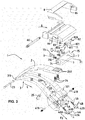
- the figure 1 illustrates a folding clasp for a timepiece 1 according to a preferred embodiment for the present invention, in which the actuation is particularly ergonomic, since it is carried out via a simple pusher 70.
- the folding clasp 1 conventionally comprises two branches, that is to say here a first central branch 2, and a second branch 3 formed of two distinct legs, the first leg 31 and the second leg 32.
- the first branch 2 and the second branch 3 are articulated around a hinge pin 23, inserted into a first fixing hole 310 of the first leg 31 and another corresponding fixing hole provided in the second leg 32, not shown in the figure. figure 1 .
- the first branch 2 is folded between the first leg 31 and the second leg 32 of the second branch 3 in the closed position of the clasp 1.
- the first central branch 2 is integral with a first bracelet strand B1, not visible in this figure but shown in the sequence of figures 2A-2E which is described below.
- the bracelet B1 is attached to the cover 6 via an attachment pin 60, while the cover 6 is itself attached to the first branch 2, preferably via one or more fixing screws 24 - here two according to the preferred embodiment illustrated - inserted into the corresponding second fixing holes 240 provided in the first branch 2.
- the second branch 3 is integral with a second strand of bracelet B2, not shown in this figure but the insertion of which into the passage 36 provided for this purpose is also shown schematically in the sequence of figures 2A-2E described in the following.
- this passage 36 on the figure 1 formed under the terminal ends of the legs of the second branch 3, that is to say under the first bulge 311 at the level of the free end of the first leg 31 and the second bulge 321 at the level of the free end of the second leg 32 and between the lower gateway 34 connecting side edges 35.
- This second strap strand B2 is preferably provided with holes in order to allow adjustment in length, and a fixing stud 25, itself integral with the second branch 3 via an insertion in a fixing hole 330 provided in an upper gateway 33 connecting the first leg 31 and the second leg 32, is provided to fix the second strand B2 in a position corresponding to a predefined length, this length being able to take a set of discrete values corresponding to the number of holes made in this second strand B2. In this way, the latter can be held in position under the second branch 3, in the locked or unlocked position of the clasp 1.
- the pusher 70 comprises two protuberances arranged symmetrically in the longitudinal direction L of the branches, namely a first protuberance 7A and a second protuberance 7B. These protuberances are arranged to fit respectively into a first retaining orifice 62A and a second retaining orifice 62B, arranged in a vertical wall 61 of the cover 6. This first retaining orifice 62A and this second retaining orifice 62B act in parallel. as holding or respectively hooking elements fixed for the retractable hooks 4A & 4B arranged on the second branch 3, as explained below.
- the pusher 70 is here fixed to the cover by means of a fixing screw 73 inserted in the central hole 610 of the vertical wall 61.
- the pusher 70 are also arranged longitudinal housings, visible in the sequence of figures 2A-2E described below, in which are inserted elastic means exerting a first return force F1 against the pusher 70.
- These elastic elements are respectively qualified as third elastic means 710 and fourth elastic means 720, in order to distinguish them from the first elastic element 5A acting on the first retractable hook 4A and second elastic element 5B acting on the second retractable hook 4B arranged on the second branch 3, as illustrated at the bottom of the figure 1 .
- the first elastic element 5A and the second elastic element 5B also exert a restoring force, referred to as the second restoring force F2 in order to differentiate it from the first restoring force F1, but which is here also arranged so as to orient itself according to the longitudinal direction L of the two branches of the clasp.
- these two return forces F1 and F2 oriented in the same direction and in the same direction accumulate to improve the security of the clasp, the force required F for unlocking can easily be made to lie above a predetermined threshold excluding any inadvertent handling error by the user.
- the first retractable hook 4A is inserted, like the first elastic element 5A, in a first housing 31A provided in the first leg 31 of the second branch 3, while, similarly, the second retractable hook 4B is inserted, likewise that the first elastic element 5B, in a second housing 32A arranged in the second leg 32 of the second branch 3.
- the first retractable hook 4A comprises a first oblong hole 40A and similarly the second retractable hook 4B comprises a second oblong hole 40B, allowing sliding of each of these hooks in the longitudinal direction L of the branches.
- Each of the hooks is moreover fixed to its respective leg of the second branch 3 by means of a fixing pin; thus the first retractable hook 4A is fixed to the first leg 31 via a first fixing pin 41A inserted in a lateral fixing hole 410A provided in the first bulge 311, and the second retractable hook 4B is similarly fixed in the second bulge of the second leg 32 via a second fixing pin 41B inserted into a corresponding lateral fixing hole (not visible on the figure 1 ) arranged in the 2 nd bulge 321.
- Each of the fixing pins that is to say the first fixing pin 41A and the second fixing pin 41B are intended to be inserted in parallel respectively into the first oblong hole 40A of the first retractable hook 4A and the second oblong hole 40B of the second retractable hook 4B.
- each of the two retractable hooks is furthermore provided with an inclined upper surface, namely a first inclined upper surface 42A on the first retractable hook 4A and a second inclined upper surface 42B on the second retractable hook 4B.
- These inclined surfaces are intended to facilitate the process of re-engaging the clasp, as explained in view of the sequence of figures 2A-2E described below.
- the two studs visible below the cover 6 consist of pawls-springs 63 exerting a repulsive force between the branches and thus making it possible to facilitate the opening of the clasp 1.
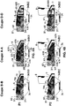
- the sequence of figures 2A-2E illustrates the clasp 1 in a first locked position P1, then in a second unlocking actuation position P2 where the two branches are still superimposed on each other but where the pusher 70 has been pressed to release the retractable hooks, then in a third unlocked position P3, where the branches are no longer superimposed on one another and the clasp is open, and then in a fourth position P4 of re-engagement of the locking mechanism, where the two branches are at again almost superimposed one on the other, and finally a fifth position P5 where the clasp is again in the locked position.
- the positions P1 and P5 are completely identical.
- the sagittal section plane via A-A passes through the first retractable hook 4A, and thus illustrates the movement of the latter during the locking and unlocking process. It may be noted that a view along a sagittal section plane crossing the second retractable hook 4B arranged symmetrically with respect to the first retractable hook 4A would be identical in all points.
- the sagittal section plane B-B passes through the third elastic element 710 exerting a restoring force against the pusher 70 and illustrating the movement of the latter during the locking and unlocking process.
- a view along a sagittal section plane crossing the fourth elastic element 720 would also be identical in all points.
- sagittal section plane C-C is a median sagittal plane passing through the cover 6 and the first central branch 2 at their center.
- the first retractable hook 4A is in its locking position, where it is compressed to the right under the action of the second return force F2 of the first elastic element 5A arranged behind it in the first longitudinal housing 31A of the first leg 31.
- the first fixing pin 41A is on the left of the first oblong hole 40A, while the first retractable hook 4A is engaged in the first hole maintenance 62A - not referenced in this figure for reasons of readability but visible further on the figure 2C - Arranged in the vertical wall 61 of the cover, as well as the first protruding part 7A of the sliding element 7 formed here by the pusher 70.
- the lower gateway 34 defining the passage 36 for the second strand B2 of the bracelet under the legs of the second branch 3.
- the sagittal sectional view along the axis B-B shows the longitudinal housings for the elastic elements intended to exert the return force against the pusher, which is here in its rest position.
- the first longitudinal housing 71 arranged directly in the pusher 70 houses the third elastic element 710 exerting the second return force F2 against the pusher, in the longitudinal direction of the branches.
- an inclined lower surface 61A at the bottom of the vertical wall 61 of the clasp which will make it possible to cooperate with the upper inclined surface of the first retractable hook (see in particular the figure in sagittal section AA of the fourth reset position P4, described below).
- the view in sagittal section along the axis CC shows the attachment of the pusher 70 to the cover via the fixing screw 73, the head of which is, in this first locking position P1, in contact with the vertical wall 61 of the cover 6.
- the difference between the first locking position P1 and the second unlocking actuation position P2 illustrated on figure 2B consists of the position of the pusher 70, on which a force F is exerted in the opposite direction to both the second return force F2 exerted on the first retractable hook and the first return force F1 exerted on the pusher 70.
- the pusher is pushed slightly to the left, so that the first protuberance 7A sinks even further into the retaining hole 62A, pushing the first retractable hook 4A in parallel to release it progressively until it is released.
- the first fixing pin 41A is then located completely in abutment on the right of the first oblong hole 40A, that is to say its other end.
- the first inclined surface 42A of the first retractable hook 4A cooperates with the lower inclined surface 61A of the vertical wall 61 of the cover 6, so that the compression of the elastic element is as progressive as possible and the wear of the clasp is reduced to a minimum.
- the inclination of each of these surfaces is preferably identical, and equal to 45 °.
- the restoring force F2 is maximum and as the cover 6 is folded over the second branch 3 (of which only the first leg 31 and the first bulge at the end thereof is shown on this 2D figure ), it will be possible to release the hook as soon as it is brought opposite the first retaining hole 62A.
- the figure 2E thus corresponds to the moment when the re-engagement of the clasp 1 is complete, so that it is again in the locked position.
- the fifth position P5 corresponds to the first locking position P1, but the latter being illustrated only at the end of an unlocking plus re-locking sequence.
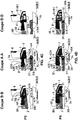
- the top of the figure 3 shows on the other hand a new actuating device for unlocking, including a lever 8 mounted to pivot about an axis of rotation 80 of the cover 6.
- This lever 8 is provided with fixing insertion holes 84, in which come s 'insert at least one cam intended to be integral in rotation with the lever 8.
- the actuating device for the unlocking comprises a first cam 81 which has a first rod 810, integral with an insertion orifice (not visible in this figure), and which is inserted into a lateral orifice 83 of the cover 6, as well as a first head 811 in egg-shaped intended to be housed in a first axial recess 74 of the sliding element 7, actuated in translation by the lever 8.
- a second cam 82 arranged symmetrically with respect to the first cam 81 vis-à-vis the cover 6, for its part has a second rod 820 fixed to the fixing hole 84 of the lever 8, and which similarly passes through another hole insertion (not visible on the figure 3 ), as well as a second head 821 having the same egg shape as the first head 811, and which is intended to be housed in a second axial recess 75 of the sliding element 7, actuated in translation by the lever 8.
- the sliding element 7 which preferably comprises the same protruding parts as the pusher 70 according to the previous embodiment - that is to say a first protuberance 7A and a second protuberance 7B, respectively being inserted into a first retaining orifice 62A and a second retaining orifice 62B (not shown in the figure 3 , but which will be visible on the sequence of figures 4A-4E following) unlocks the clasp in the same way as according to the embodiment described above, that is to say by acting on the retractable hooks 4A, 4B in the longitudinal direction L of the branches against the second force return F2 exerted by the first elastic element 5A and the second elastic element 5B.
- the essential difference relates only to the mode of actuation in translation of this sliding element 7, which is merged with a pusher 70 according to the first embodiment of the figure 1 to form one and the same part, while this sliding element 7 cannot be actuated directly by hand, but on the contrary indirectly via the lever 8 which then becomes the actuating part that must be gripped and manipulated by the user.
- the solution according to the mode of realization of the figure 1 is more ergonomic, that is to say more user-friendly and easier to handle, for example using the single index finger of the hand opposite to that in which the watch is worn, but conversely, the solution proposed according to the embodiment illustrated on the figure 3 guarantees maximum reliability of use, because it is almost impossible to activate the unlocking of the clasp by mistake.
- the sequence of figures 4A-4E illustrates the clasp 1 in the same positions P1-P5 as those of figures 2A-2E , that is to say a first locked position P1, then in a second unlocking actuation position P2 where the two branches are still superimposed on each other but where the sliding element 7 has been pushed by the cams in order to release the retractable hooks, then in a third unlocked position P3, where the branches are no longer superimposed on one another and the clasp is open, and then in a fourth position P4 for re-engaging the mechanism locking, where the two branches are again almost superimposed on one another, and finally a fifth position P5 where the clasp is again in the locked position.
- the positions P1 and P5 are completely identical.
- the first fixing axis 41A is located on the left of the first oblong hole 40A, while the first retractable hook 4A is engaged in the first retaining hole 62A - not referenced in this figure for reasons of readability but visible further on the figure 4C - Arranged in the vertical wall 61 of the cover, as well as the first protruding part 7A of the sliding element 7 hidden under the cover 6. Affixed on the cover 6, one can also distinguish a part of the lever 8. Under this device of locking the clasp, we can also distinguish the lower gateway 34 defining the passage 36 for the second strand B2 of the bracelet under the legs of the second branch 3.
- the view in sagittal section along the axis BB of the figure 4A highlights the longitudinal housings for the elastic elements intended to exert the return force against the sliding element 7, which is here in its rest position.
- the first longitudinal housing 71 arranged directly in the sliding element 7 houses the third elastic element 710 exerting the first return force F1 against the pusher, in the longitudinal direction L of the branches.
- the view in sagittal section along the axis DD shows the relationship between the position of the lever 8 and the position of the first cam 81, of which the head is here oriented downwards (that is to say the first head 811 with its tapered part pointing downwards).
- the first cam 81 does not act on the sliding element, which is held in position via the first return force F1 exerted by the third elastic member 710 and the fourth elastic member 720 (not shown).
- the difference between the first locking position P1 and the second unlocking actuation position P2 illustrated on figure 4B consists of the position of the lever 8, now pulled upwards, and which makes it possible to exert a force F in the opposite direction to both the first return force F1 exerted on the sliding element 7 and the second force of recall F2 exerted on the first retractable hook 4A.
- the sliding element under the impulse of the first head 811 of the first cam 81, the sliding element is depressed slightly to the left, so that the first protuberance 7A sinks even more into the retaining hole 62A, pushing back at the same time, the first retractable hook 4A to gradually release it until it is released.
- the first fixing pin 41A is then completely in abutment on the right of the first oblong hole 40A, that is to say its other end relative to that where it is located. found on the figure 4A previous along the AA axis.
- the first inclined surface 42A of the first retractable hook 4A cooperates with the lower inclined surface 61A of the vertical wall 61 of the cover 6, so that the compression of the elastic element is as progressive as possible and that the wear of the clasp is reduced to a minimum.
- the inclination of each of these surfaces is preferably identical, and equal to 45 °.
- the restoring force F2 is maximum and as the cover 6 is folded over the second branch 3 (of which only the first leg 31 and the first bulge at the end thereof is shown on this figure 4D ), it will be possible to release the hook as soon as it is brought opposite the first retaining hole 62A.
- the figure 4E thus corresponds to the moment when the re-engagement of the clasp 1 is complete, so that it is again in the locked position.
- the fifth position P5 corresponds to the first locking position P1, but the latter being illustrated only at the end of an unlocking plus re-locking sequence.
Abstract
Fermoir (1) à boucle déployante pour montre-bracelet comprenant au moins une première branche (2) et une deuxième branche (3) articulées l'une par rapport à l'autre autour d'un axe (23), comprenant d'une part des moyens de liaison des extrémités libres de chacune des branches (2,3) à des brins respectifs d'un bracelet, et d'autre part un dispositif de verrouillage pour maintenir les branches (2,3) en position repliée l'une sur l'autre en position fermée du bracelet, le dispositif de verrouillage comprenant au moins un crochet rétractable (4A,4B) agencé sur la deuxième branche (3), qui coopère avec au moins des moyens d'accrochage fixes (62A,62B) agencés sur un couvercle (6) solidaire de la première branche (2) en position de verrouillage, le crochet rétractable (4A,4B) étant maintenu en position de verrouillage par un élément élastique (5A,5B), et comprenant par ailleurs un élément coulissant (7), agencé dans le couvercle (6) et maintenu dans une position au repos par au moins un autre élément élastique (710,720), l'élément coulissant (7) étant agencé pour libérer le crochet rétractable (4A,4B) lorsque l'on agit à l'encontre de la force de rappel exercée par l'autre élément élastique (710,720).Clasp (1) with folding clasp for a wristwatch comprising at least a first branch (2) and a second branch (3) articulated with respect to one another around an axis (23), comprising a on the one hand means for connecting the free ends of each of the branches (2,3) to respective strands of a bracelet, and on the other hand a locking device for holding the branches (2,3) in the folded position one on the other in the closed position of the bracelet, the locking device comprising at least one retractable hook (4A, 4B) arranged on the second branch (3), which cooperates with at least fixed hooking means (62A, 62B) arranged on a cover (6) integral with the first branch (2) in the locking position, the retractable hook (4A, 4B) being held in the locking position by an elastic element (5A, 5B), and further comprising an element sliding (7), arranged in the cover (6) and held in a rest position by at least one other elastic element (710,720), the sliding element (7) being arranged to release the retractable hook (4A, 4B) when acting against the restoring force exerted by the other elastic element (710,720).
Description
La présente invention se rapporte au domaine de l'horlogerie, et en particulier un fermoir pour une montre-bracelet.The present invention relates to the field of watchmaking, and in particular to a clasp for a wristwatch.
On connaît des fermoirs du type à boucle déployante à deux branches repliées l'une sur l'autre en position fermée, et qui permettent à l'utilisateur d'insérer son poignet dans le bracelet en position ouverte sans devoir séparer les deux brins grâce à l'augmentation de diamètre conférée. Un tel agencement permet d'améliorer la sécurité et le confort d'usage, en permettant d'une part d'enfiler simplement la montre-bracelet sur son poignet, et de l'enlever tout aussi rapidement et efficacement, sans devoir séparer les brins du bracelet; d'autre part, de tels dispositifs combinés d'attache et de verrouillage de bracelet permettent d'éviter que la montre ne puisse tomber si les deux brins devaient se désolidariser l'un de l'autre en cas de dysfonctionnement du système de verrouillage.There are known clasps of the folding clasp type with two branches folded over one another in the closed position, and which allow the user to insert his wrist into the bracelet in the open position without having to separate the two strands thanks to the increase in diameter conferred. Such an arrangement makes it possible to improve safety and comfort of use, by making it possible, on the one hand, to simply put the wristwatch on his wrist, and to remove it just as quickly and efficiently, without having to separate the strands. of the bracelet; on the other hand, such combined devices for fastening and locking the bracelet make it possible to prevent the watch from falling if the two strands were to become detached from one another in the event of a malfunction of the locking system.
Outre les fermoirs à deux branches, on connaît par ailleurs des dispositifs à trois branches, également appelés « papillon », où deux petites branches latérales agencées symétriquement et articulées autour des extrémités d'une branche centrale viennent se replier au centre de celle-ci. Quel que soit le nombre de branches du fermoir, la solution la plus usuelle consiste à agencer deux poussoirs dans les parois un couvercle que l'on vient pincer de part et d'autre du couvercle pour ouvrir le fermoir et libérer des crochets agencés perpendiculairement à l'axe longitudinal des branches. L'inconvénient de ce type de fermoir où les crochets sont agencés à l'extrémité de lames flexibles est la fiabilité du dispositif de verrouillage au fil du temps.Besides the clasps with two branches, there are also known devices with three branches, also called "butterfly", where two small side branches arranged symmetrically and articulated around the ends of a central branch come to be folded in the center thereof. Whatever the number of branches of the clasp, the most usual solution consists in arranging two pushers in the walls of a cover which is clamped on either side of the cover to open the clasp and release hooks arranged perpendicular to the cover. the longitudinal axis of the branches. The disadvantage of this type of clasp where the hooks are arranged at the end of flexible blades is the reliability of the locking device over time.
Par ailleurs, il existe un grand nombre de système d'accrochage ou de verrouillage utilisant les propriétés élastiques des branches dépliantes du fermoir; un inconvénient de ce type de fermoirs est toutefois d'être tributaire du matériau et des dimensions des branches dépliantes elles-mêmes.In addition, there are a large number of hooking or locking systems using the elastic properties of the folding branches of the clasp; a drawback of this type of clasps is, however, that it depends on the material and the dimensions of the folding branches themselves.
Il existe par conséquent un besoin pour une solution exempte de ces limitations connues.There is therefore a need for a solution free from these known limitations.
Un but de la présente invention est de fournir une solution alternative de verrouillage pour un fermoir, qui soit facilement actionnable par le porteur de la montre-bracelet et dont la fiabilité soit garantie au fil du temps.An aim of the present invention is to provide an alternative locking solution for a clasp, which can be easily actuated by the wearer of the wristwatch and whose reliability is guaranteed over time.
Un autre but de la présente invention est de permettre un déverrouillage plus sûr du fermoir.Another object of the present invention is to allow a more secure unlocking of the clasp.
Selon l'invention, ces buts sont atteints grâce à un fermoir pour pièce d'horlogerie conformément aux caractéristiques de la revendication principale; les caractéristiques des revendications dépendantes se rapportent à des modes de réalisation avantageux.According to the invention, these objects are achieved by means of a clasp for a timepiece in accordance with the characteristics of the main claim; the characteristics of the dependent claims relate to advantageous embodiments.
En particulier, ces buts sont atteints grâce à un fermoir à boucle déployante pour montre-bracelet comprenant au moins une première branche et une deuxième branche articulées l'une par rapport à l'autre autour d'un axe, comprenant d'une part des moyens de liaison des extrémités libres de chacune des première branche et deuxième branche à des brins respectifs d'un bracelet, et d'autre part un dispositif de verrouillage pour maintenir les première branche et deuxième branche en position repliée l'une sur l'autre en position fermée du bracelet, caractérisé en ce que le dispositif de verrouillage comprend au moins un crochet rétractable agencé sur la deuxième branche, qui coopère avec au moins des moyens d'accrochage fixes agencés sur un couvercle solidaire de la première branche en position de verrouillage, le crochet rétractable étant maintenu en position de verrouillage par un élément élastique, et comprend par ailleurs un élément coulissant, agencé dans le couvercle et maintenu dans une position au repos par au moins un autre élément élastique, l'élément coulissant étant agencé pour libérer le crochet rétractable lorsque l'on agit à l'encontre de la force de rappel exercée par l'autre élément élastique.In particular, these goals are achieved by virtue of a folding clasp for a wristwatch comprising at least a first branch and a second branch articulated with respect to one another around an axis, comprising on the one hand means for connecting the free ends of each of the first branch and second branch to respective strands of a bracelet, and on the other hand a locking device for holding the first branch and second branch in the folded position one over the other in the closed position of the bracelet, characterized in that the locking device comprises at least one retractable hook arranged on the second branch, which cooperates with at least fixed hooking means arranged on a cover integral with the first branch in the locking position , the retractable hook being held in the locking position by an elastic element, and further comprises a sliding element, arranged in the cover and held in a e position at rest by at least one other elastic element, the sliding element being arranged to release the retractable hook when acting against the restoring force exerted by the other elastic element.
Un avantage de la solution proposée est de fournir un nouveau fermoir pourvu d'un système de verrouillage alternatif dont la fiabilité et la durabilité sont accrues grâce au mouvement coulissant des crochets de verrouillage.An advantage of the proposed solution is to provide a new clasp provided with an alternative locking system, the reliability and durability of which are increased thanks to the sliding movement of the locking hooks.
Selon un mode de réalisation préférentiel du fermoir à boucle déployante selon l'invention, l'élément coulissant se déplace selon l'axe longitudinal des première branche et deuxième branche.According to a preferred embodiment of the folding clasp according to the invention, the sliding element moves along the longitudinal axis of the first branch and second branch.
Un avantage de la solution proposée selon ce mode de réalisation est de fournir un nouveau fermoir pourvu d'un système de verrouillage plus intuitif, en raison de l'espace plus grand disponible dans le sens de la longueur des branches.An advantage of the solution proposed according to this embodiment is to provide a new clasp provided with a more intuitive locking system, due to the greater space available in the direction of the length of the branches.
Selon un autre mode de réalisation préférentiel du fermoir à boucle déployante selon l'invention, au moins un crochet rétractable se déplace par ailleurs selon l'axe longitudinal des première branche et deuxième branche.According to another preferred embodiment of the folding clasp according to the invention, at least one retractable hook also moves along the longitudinal axis of the first branch and second branch.
Un avantage de la solution proposée selon ce mode de réalisation préférentiel est de fournir un dispositif de verrouillage et de déverrouillage encore plus sécurisé, en raison des forces de rappel appliquées à l'élément coulissant et au crochet rétractables qui peuvent s'additionner.An advantage of the solution proposed according to this preferred embodiment is to provide an even more secure locking and unlocking device, owing to the return forces applied to the sliding element and to the retractable hook which can be added.
Selon un mode de réalisation préférentiel du fermoir à boucle déployante selon l'invention, le crochet rétractable possède une surface supérieure inclinée.According to a preferred embodiment of the folding clasp according to the invention, the retractable hook has an inclined upper surface.
Un avantage de la solution proposée selon ce mode de réalisation préférentiel est de faciliter le mécanisme de réenclenchement des crochets dans leur position de verrouillage, ce qui par conséquent minimise leur usure et préserve leur durée de vie.An advantage of the solution proposed according to this preferred embodiment is to facilitate the mechanism for re-engaging the hooks in their locking position, which consequently minimizes their wear and preserves their lifetime.
Selon un mode de réalisation préférentiel du fermoir à boucle déployante selon l'invention, la première branche est une branche centrale, alors que la deuxième branche est formée par deux jambes, à savoir une première jambe et une deuxième jambe, un premier logement longitudinal étant prévu pour loger un premier crochet rétractable ainsi qu'un premier élément élastique, et un deuxième logement longitudinal étant prévu pour loger un deuxième crochet rétractable ainsi qu'un deuxième élément élastique.According to a preferred embodiment of the folding clasp according to the invention, the first branch is a central branch, while the second branch is formed by two legs, namely a first leg and a second leg, a first longitudinal housing being provided to house a first retractable hook as well as a first elastic element, and a second longitudinal housing being provided to house a second retractable hook as well as a second elastic element.
Un avantage de la solution proposée selon ce mode de réalisation préférentiel est de permettre une intégration facile à une structure de fermoir à boucle déployante classique, et augmentant par ailleurs la force de rappel grâce à l'emploi de plusieurs crochets dont l'agencement symétrique sur chacune des jambes permet d'ailleurs d'optimiser les propriétés de guidage.An advantage of the solution proposed according to this preferred embodiment is to allow easy integration into a conventional folding clasp structure, and also increasing the restoring force through the use of several hooks whose symmetrical arrangement on each of the legs also makes it possible to optimize the guiding properties.
Selon un mode de réalisation préférentiel du fermoir à boucle déployante selon l'invention, le premier logement longitudinal est aménagé dans un premier renflement au niveau de l'extrémité libre de la première jambe, et le deuxième logement longitudinal étant aménagé dans un deuxième renflement au niveau de l'extrémité libre de la deuxième jambe pour y loger lesdits crochets rétractables respectifs.According to a preferred embodiment of the folding clasp according to the invention, the first longitudinal housing is arranged in a first bulge at the level of the free end of the first leg, and the second longitudinal recess being arranged in a second bulge at the level of the free end of the first leg. level of the free end of the second leg to accommodate said respective retractable hooks therein.
Un avantage de la solution proposée selon ce mode de réalisation préférentiel est de pouvoir augmenter la taille des crochets et des éléments élastiques de rappel, afin de maximiser la fiabilité du verrouillage.An advantage of the solution proposed according to this preferred embodiment is to be able to increase the size of the hooks and of the elastic return elements, in order to maximize the reliability of the locking.
Selon un mode de réalisation préférentiel du fermoir à boucle déployante selon l'invention, le crochet rétractable possède un trou oblong dans lequel est inséré un axe de fixation perpendiculaire à l'axe longitudinal des première branche et deuxième branche.According to a preferred embodiment of the folding clasp according to the invention, the retractable hook has an oblong hole in which is inserted a fixing axis perpendicular to the longitudinal axis of the first branch and second branch.
Un avantage de la solution proposée selon ce mode de réalisation préférentiel est de permettre un montage simple du ou des crochets, tout en maximisant leurs propriétés de guidage par coulissement selon l'axe longitudinal des branches.An advantage of the solution proposed according to this preferred embodiment is that it allows simple assembly of the hook or hooks, while maximizing their guiding properties by sliding along the longitudinal axis of the branches.
Selon un mode de réalisation préférentiel du fermoir à boucle déployante selon l'invention, les éléments d'accrochage fixes sont formés par des orifices formés dans une paroi verticale du couvercle.According to a preferred embodiment of the folding clasp according to the invention, the fixed hooking elements are formed by orifices formed in a vertical wall of the cover.
Un avantage de la solution proposée selon ce mode de réalisation préférentiel est de rendre l'agencement des éléments d'accrochage le plus simple et le moins onéreux possible, en les intégrant à une pièce existante telle que le couvercle, et ce sans nécessiter aucun ajout de matière ni devoir générer de forme géométrique complexe. Par ailleurs, ces éléments d'accrochage restent cachés sous le couvercle, ce qui garantit le maintien des propriétés esthétiques du fermoir.An advantage of the solution proposed according to this preferred embodiment is to make the arrangement of the fastening elements as simple and as inexpensive as possible, by integrating them into an existing part such as the cover, and this without requiring any addition. of material nor having to generate a complex geometric shape. Moreover, these fastening elements remain hidden under the cover, which guarantees that the aesthetic properties of the clasp are maintained.
Selon un mode de réalisation préférentiel du fermoir à boucle déployante selon l'invention, l'élément coulissant comporte une première protubérance et une deuxième protubérance s'étendant selon l'axe longitudinal des première branche et deuxième branche, la première protubérance étant agencée pour pouvoir s'introduire dans ledit premier orifice et la deuxième protubérance étant agencée pour pouvoir s'introduire dans le deuxième orifice.According to a preferred embodiment of the folding clasp according to the invention, the sliding element comprises a first protuberance and a second protuberance extending along the longitudinal axis of the first branch and second branch, the first protuberance being arranged to be able to to be introduced into said first orifice and the second protuberance being arranged so as to be able to be introduced into the second orifice.
Un avantage de la solution proposée selon ce mode de réalisation préférentiel est de garantir, par un tel agencement symétrique via l'agencement de protubérances coopérant respectivement avec les éléments d'accrochage du couvercle, d'excellentes propriétés de guidage de l'élément coulissant selon l'axe longitudinal des branches.An advantage of the solution proposed according to this preferred embodiment is to guarantee, by such a symmetrical arrangement via the arrangement of protuberances cooperating respectively with the catching elements of the cover, excellent guiding properties of the sliding element according to the longitudinal axis of the branches.
Selon un mode de réalisation préférentiel du fermoir à boucle déployante selon l'invention, l'élément coulissant est un poussoir accessible depuis l'avant du couvercle.According to a preferred embodiment of the folding clasp according to the invention, the sliding element is a pusher accessible from the front of the cover.
Un avantage de la solution proposée selon ce mode de réalisation préférentiel est de maximiser les propriétés ergonomiques du fermoir, dont le déverrouillage peut désormais être actionné via un seul doigt. La facilité d'actionnement en est ainsi considérablement améliorée par rapport aux fermoirs usuels nécessitant la préhension soit d'un levier, soit l'actionnement simultané de poussoirs latéraux.One advantage of the solution proposed according to this preferred embodiment is that it maximizes the ergonomic properties of the clasp, the unlocking of which can now be actuated via a single finger. The ease of actuation is thus considerably improved compared to the usual clasps requiring the gripping either of a lever, or the simultaneous actuation of lateral pushers.
Selon un mode de réalisation préférentiel du fermoir à boucle déployante selon l'invention, l'élément coulissant est actionné par un levier monté pivotant par rapport au couvercle selon un axe de rotation perpendiculaire à l'axe longitudinal des première branche et deuxième branche.According to a preferred embodiment of the folding clasp according to the invention, the sliding element is actuated by a lever mounted to pivot relative to the cover along an axis of rotation perpendicular to the longitudinal axis of the first branch and second branch.
Un avantage de la solution proposée selon ce mode de réalisation préférentiel est de maximiser la sécurité du fermoir, dont le déverrouillage est ainsi quasiment impossible via une mauvaise manipulation de l'utilisateur ou encore un choc vis-à-vis d'un élément extérieur.One advantage of the solution proposed according to this preferred embodiment is that it maximizes the security of the clasp, the unlocking of which is thus almost impossible via poor handling by the user or even a shock to an external element.
Selon un mode de réalisation préférentiel du fermoir à boucle déployante selon l'invention, l'axe du levier étant solidaire de cames agissant sur l'élément coulissant.According to a preferred embodiment of the folding clasp according to the invention, the axis of the lever being integral with cams acting on the sliding element.
Un avantage de la solution proposée selon ce mode de réalisation préférentiel est de transmettre très simplement le mouvement de pivotement du levier à l'élément coulissant caché sous le couvercle. Ainsi, l'intégration du mécanisme de transmission de la force de déverrouillage est simplifiée.An advantage of the solution proposed according to this preferred embodiment is to very simply transmit the pivoting movement of the lever to the sliding element hidden under the cover. Thus, the integration of the unlocking force transmission mechanism is simplified.
Selon un mode de réalisation préférentiel du fermoir à boucle déployante selon l'invention, une première came est disposée dans un premier renfoncement axial de l'élément coulissant, et une deuxième came est disposée dans un deuxième renfoncement axial de l'élément coulissant.According to a preferred embodiment of the folding clasp according to the invention, a first cam is arranged in a first axial recess of the sliding element, and a second cam is arranged in a second axial recess of the sliding element.
Un avantage de la solution proposée selon ce mode de réalisation préférentiel est d'optimiser la fiabilité d'actionnement via l'agencement de cames symétriques disposées de part et d'autre de l'axe longitudinal des branches, tout en préservant parallèlement l'esthétique du fermoir.An advantage of the solution proposed according to this preferred embodiment is to optimize the reliability of actuation via the arrangement of symmetrical cams arranged on either side of the longitudinal axis of the branches, while at the same time preserving the aesthetics. of the clasp.
Selon un mode de réalisation préférentiel du fermoir à boucle déployante selon l'invention, l'élément coulissant est pourvu d'un premier logement longitudinal pour loger un troisième élément élastique et d'un deuxième logement longitudinal pour loger un quatrième élément élastique.According to a preferred embodiment of the folding clasp according to the invention, the sliding element is provided with a first longitudinal housing for accommodating a third elastic element and with a second longitudinal housing for accommodating a fourth elastic element.
Un avantage de la solution proposée selon ce mode de réalisation préférentiel est de faciliter l'intégration d'éléments destinés à exercer une force de rappel à l'encontre de l'élément coulissant directement dans celui-ci. Ainsi il est facile de générer facilement une force de rappel selon l'axe longitudinal qui pourra de préférence s'additionner à celle exercée par les crochets.An advantage of the solution proposed according to this preferred embodiment is to facilitate the integration of elements intended to exert a restoring force against the sliding element directly therein. Thus, it is easy to easily generate a return force along the longitudinal axis which can preferably be added to that exerted by the hooks.
D'autres modes de réalisation préférentiels seront par ailleurs détaillés dans la description qui suit.Other preferred embodiments will moreover be detailed in the following description.
On comprendra du reste de cette description détaillée que les caractéristiques avantageuses tirées des modes de réalisations préférentiels pourront être pris isolément ou en combinaison, sauf lorsque ceux-ci seront présentés comme mutuellement exclusifs, comme par exemple pour l'actionnement du déverrouillage via un poussoir ou un levier évoqués dans ce qui précède.It will be understood from the rest of this detailed description that the advantageous characteristics drawn from the preferred embodiments can be taken individually or in combination, except when these will be presented as mutually exclusive, such as for example for the actuation of the unlocking via a push-button or a lever mentioned in the above.
D'autres caractéristiques avantageuses ressortiront plus clairement de la description qui suit d'un mode de réalisation particulier de l'invention donné à titre d'exemple non limitatif et représenté par les dessins annexés, dans lesquels:
- la
figure 1 est une vue éclatée selon un mode de réalisation préférentiel pour l'invention, selon lequel le déverrouillage du fermoir est actionné par un poussoir; - la séquence des
figures 2A,2B,2C ,2D et 2E montre des vues en coupe du mode de réalisation préférentiel pour l'invention illustré par lafigure 1 précédente, respectivement selon les plans de coupe A-A, B-B et C-C illustrés sur cette figure, selon différentes positions P1-P5 illustrant le passage d'une position verrouillée à une position déverrouillée, et vice-versa, via le mécanisme de verrouillage et respectivement déverrouillage proposé selon l'invention; - la
figure 3 est une vue éclatée selon un mode de réalisation préférentiel pour l'invention, selon lequel le déverrouillage du fermoir est actionné par un levier; - la séquence des
figures 4A,4B ,4C,4D et4E montre des vues en coupe du mode de réalisation préférentiel pour l'invention illustré par lafigure 3 qui précède, respectivement selon les plans de coupe B-B, A-A et D-D illustrés sur cette même figure, selon les mêmes différentes positions P1-P5 que celles de la séquence de figures relative au mode de réalisation précédent, illustrant le passage d'une position verrouillée à une position déverrouillée, et vice-versa, via le mécanisme de verrouillage et respectivement déverrouillage proposé selon l'invention.
- the
figure 1 is an exploded view according to a preferred embodiment for the invention, according to which the unlocking of the clasp is actuated by a pusher; - the sequence of
figures 2A, 2B, 2C ,2D and 2E shows sectional views of the preferred embodiment for the invention illustrated byfigure 1 previous, respectively according to the section planes AA, BB and CC illustrated in this figure, according to different positions P1-P5 illustrating the passage from a locked position to an unlocked position, and vice versa, via the locking and unlocking mechanism respectively proposed according to the invention; - the
figure 3 is an exploded view according to a preferred embodiment for the invention, according to which the unlocking of the clasp is actuated by a lever; - the sequence of
figures 4A, 4B ,4C, 4D and4E shows sectional views of the preferred embodiment for the invention illustrated byfigure 3 which precedes, respectively according to the section planes BB, AA and DD illustrated in this same figure, according to the same different positions P1-P5 as those of the sequence of figures relating to the previous embodiment, illustrating the passage from a locked position to an unlocked position, and vice versa, via the locking and unlocking mechanism respectively proposed according to the invention.
La
Le fermoir 1 à boucle déployante comprend classiquement deux branches, c'est-à-dire ici une première branche centrale 2, et une deuxième branche 3 formée de deux jambes distinctes, la première jambe 31 et la deuxième jambe 32. La première branche 2 et la deuxième branche 3 sont articulées autour d'un axe d'articulation 23, inséré dans un premier orifice de fixation 310 de la première jambe 31 et un autre orifice de fixation correspondant aménagé dans la deuxième jambe 32, non illustré sur la
La première branche 2 centrale est solidaire d'un premier brin de bracelet B1, non visible sur cette figure mais représenté sur la séquence de
La deuxième branche 3 est solidaire d'un deuxième brin de bracelet B2, non représenté sur cette figure mais dont l'insertion dans le passage 36 prévu à cet effet est schématiquement représenté également sur la séquence de
En haut de la
Le poussoir 70 est ici fixé au couvercle par l'intermédiaire d'une vis de fixation 73 insérée dans le trou central 610 de la paroi verticale 61. Dans le poussoir 70 sont également aménagés des logements longitudinaux, visibles sur la séquence de
Selon le mode de réalisation préférentiel illustré sur la
Chacun de crochets est par ailleurs fixé à sa jambe respective de la deuxième branche 3 à l'aide d'un axe de fixation; ainsi le premier crochet rétractable 4A est fixé à la première jambe 31 via un premier axe de fixation 41A inséré dans un orifice latéral de fixation 410A aménagé dans le premier renflement 311, et le deuxième crochet rétractable 4B est similairement fixé dans le deuxième renflement de la deuxième jambe 32 via un deuxième axe de fixation 41B inséré dans un orifice latéral de fixation correspondant (non visible sur la
Comme on peut par ailleurs le discerner en bas à droite de la
La séquence de
Chacune de ces cinq positions sont décrites à l'aide de trois vues en coupe, correspondant à des plans de coupe sagittaux du fermoir 1 traversant les axes A-A, B-B, et C-C du fermoir 1 illustrés sur la
Le plan de coupe sagittal via A-A traverse le premier crochet rétractable 4A, et illustre ainsi le mouvement de ce dernier lors du processus de verrouillage et de déverrouillage. On pourra noter qu'une vue selon un plan de coupe sagittal traversant le deuxième crochet rétractable 4B agencé symétriquement par rapport au premier crochet rétractable 4A serait en tous points identique.The sagittal section plane via A-A passes through the first
Le plan de coupe sagittal B-B traverse le troisième élément élastique 710 exerçant une force de rappel à l'encontre du poussoir 70 et illustrant le mouvement de ce dernier lors du processus de verrouillage et de déverrouillage. Comme pour la vue en coupe précédente, on pourra noter qu'une vue selon un plan de coupe sagittal traversant le quatrième élément élastique 720 serait également en tous points identique.The sagittal section plane B-B passes through the third
Enfin, le plan de coupe sagittal C-C est un plan sagittal médian traversant le couvercle 6 et la première branche 2 centrale en leur centre.Finally, the sagittal section plane C-C is a median sagittal plane passing through the
Dans ce qui suit, on décrira les différentes positions P1, P2, P3, P4 (et P5 correspondant à nouveau à P1) en se référant indifféremment aux différents axes de coupe A-A, B-B et C-C.In what follows, the various positions P1, P2, P3, P4 (and P5 corresponding again to P1) will be described with indifference to the various cutting axes A-A, B-B and C-C.
Sur la
La vue en coupe sagittale selon l'axe B-B met en évidence les logements longitudinaux pour les éléments élastiques destinés à exercer la force de rappel à l'encontre du poussoir, qui se trouve ici dans sa position au repos. Ainsi, le premier logement longitudinal 71 agencé directement dans le poussoir 70 loge le troisième élément élastique 710 exerçant la deuxième force de rappel F2 à l'encontre du poussoir, dans le sens longitudinal des branches. Sur cette vue en coupe, on peut également distinguer une surface inférieure inclinée 61A au bas de la paroi verticale 61 du fermoir, qui permettra de coopérer avec la surface inclinée supérieure du premier crochet rétractable (voir notamment la figure en coupe sagittale A-A de la quatrième position de ré-enclenchement P4, décrite ci-après).The sagittal sectional view along the axis B-B shows the longitudinal housings for the elastic elements intended to exert the return force against the pusher, which is here in its rest position. Thus, the first
Enfin, la vue en coupe sagittale selon l'axe C-C met en évidence la fixation du poussoir 70 au couvercle via la vis de fixation 73, dont la tête est, dans cette première position P1 de verrouillage, en contact avec la paroi verticale 61 du couvercle 6.Finally, the view in sagittal section along the axis CC shows the attachment of the pusher 70 to the cover via the fixing
La différence entre la première position P1 de verrouillage et la deuxième position P2 d'actionnement du déverrouillage illustrée sur la
Sur la vue en coupe sagittale selon l'axe C-C, on peut par ailleurs bien visualiser que la base de la tête de la vis de fixation 73 du poussoir 70 n'est désormais plus en appui sur la paroi verticale 61 du couvercle, mais s'est légèrement décalée vers la gauche.On the view in sagittal section along the axis CC, it can also be clearly seen that the base of the head of the fixing
Dans la troisième position déverrouillée P3, illustrée sur la
Dans la quatrième position P4, illustrée sur la
La
Dans le mode de réalisation préférentiel qui suit, correspondant à un mode d'actionnement du déverrouillage via un levier et qui est illustré par la
En comparant les
Le haut de la
Une deuxième came 82, agencée symétriquement par rapport à la première came 81 vis-à-vis du couvercle 6, possède quant à elle une deuxième tige 820 fixée à l'orifice de fixation 84 du levier 8, et qui traverse similairement un autre orifice d'insertion (non visible sur la
De cette manière, l'actionnement de l'élément coulissant 7 en translation s'effectue via l'actionnement du levier 8 en rotation, dont le mouvement rotatif est transformé en mouvement d'actionnement en translation selon la direction longitudinale via les première came 81 et deuxième came 82. Dès lors, l'élément coulissant 7, qui comprend de préférence les mêmes parties protubérantes que le poussoir 70 selon le mode de réalisation précédent - c'est-à-dire une première protubérance 7A et une deuxième protubérance 7B, venant respectivement s'insérer dans un premier orifice de maintien 62A et un deuxième orifice de maintien 62B (non représentés sur la
La séquence de
Chacune de ces cinq positions sont décrites à l'aide de trois vues en coupe, correspondant à des plans de coupe sagittaux du fermoir 1 traversant les axes A-A, B-B et D-D du fermoir 1 illustrés sur la
Etant donné les nombreuses similitudes entre les
Sur la
La vue en coupe sagittale selon l'axe B-B de la
Enfin, la vue en coupe sagittale selon l'axe D-D met en évidence la relation entre la position du levier 8 et la position de la première came 81, dont la tête est ici orientée vers le bas (c'est-à-dire la première tête 811 avec sa partie effilée pointant vers le bas). Dans cette première position de verrouillage P1 où le levier 8 est apposé au couvercle 6, on peut constater que la première came 81 n'agit pas sur l'élément coulissant, qui est maintenu en position via la première force de rappel F1 exercée par le troisième élément élastique 710 et le quatrième élément élastique 720 (non illustré).Finally, the view in sagittal section along the axis DD shows the relationship between the position of the
La différence entre la première position P1 de verrouillage et la deuxième position P2 d'actionnement du déverrouillage illustrée sur la
Sur la vue en coupe sagittale selon l'axe D-D, on peut par ailleurs bien visualiser l'action de la première tête 811 de la première came 81 poussant l'élément coulissant à se décaler vers la gauche.On the view in sagittal section along the D-D axis, it is also possible to clearly visualize the action of the
Dans la troisième position déverrouillée P3, illustrée sur la
Dans la quatrième position P4, illustrée sur la
La
On comprendra de la description qui précède que les modes de réalisation décrits ne sont donnés qu'à titre d'exemple, sans toutefois avoir pour vocation d'interpréter les revendications de façon limitative.It will be understood from the above description that the embodiments described are given only by way of example, without however being intended to interpret the claims in a limiting manner.
D'autres variantes sont également possibles sans sortir du cadre de la présente invention, notamment en ce qui concerne le nombre de crochets rétractables, le nombre correspondant d'éléments élastiques agissant sur ces crochets, le nombre de parties protubérantes agissant sur ceux-ci pour les déverrouiller ainsi que le mode de fixation de l'élément coulissant au couvercle ainsi que le nombre d'élément élastiques agissant sur celui-ci. On pourrait également envisager un mécanisme alternatif de came n'utilisant qu'une came centrale, ainsi que d'autres modes de fixation de l'élément coulissant au couvercle, indépendamment du mode d'actionnement de celui-ci en translation (c'est-à-dire via un mécanisme de poussoir ou de levier associé à un système de cames).Other variants are also possible without departing from the scope of the present invention, in particular as regards the number of retractable hooks, the corresponding number of elastic elements acting on these hooks, the number of protruding parts acting on them for unlock them as well as the method of fixing the sliding element to the cover as well as the number of elastic elements acting on it. One could also envisage an alternative cam mechanism using only a central cam, as well as other methods of fixing the sliding element to the cover, independently of the mode of actuation of the latter in translation (i.e. i.e. via a pusher or lever mechanism associated with a cam system).
Claims (14)
Priority Applications (1)
| Application Number | Priority Date | Filing Date | Title |
|---|---|---|---|
| EP20151703.4A EP3850980A1 (en) | 2020-01-14 | 2020-01-14 | Clasp for a timepiece |
Applications Claiming Priority (1)
| Application Number | Priority Date | Filing Date | Title |
|---|---|---|---|
| EP20151703.4A EP3850980A1 (en) | 2020-01-14 | 2020-01-14 | Clasp for a timepiece |
Publications (1)
| Publication Number | Publication Date |
|---|---|
| EP3850980A1 true EP3850980A1 (en) | 2021-07-21 |
Family
ID=69167707
Family Applications (1)
| Application Number | Title | Priority Date | Filing Date |
|---|---|---|---|
| EP20151703.4A Withdrawn EP3850980A1 (en) | 2020-01-14 | 2020-01-14 | Clasp for a timepiece |
Country Status (1)
| Country | Link |
|---|---|
| EP (1) | EP3850980A1 (en) |
Citations (4)
| Publication number | Priority date | Publication date | Assignee | Title |
|---|---|---|---|---|
| EP0344620A1 (en) * | 1988-05-31 | 1989-12-06 | G.T.F. S.r.l. | Closing device for watch-straps, bracelets, jewels and similar |
| US20080267014A1 (en) * | 2007-04-25 | 2008-10-30 | Hyatt Dequincy A | Tracking and monitoring system |
| EP2644050A1 (en) * | 2012-03-27 | 2013-10-02 | Rolex S.A. | Opening clasp for bracelet |
| CN205923169U (en) * | 2016-07-07 | 2017-02-08 | 裘里斯杨 | Preceding pushing away is put off long table after opening and is buckled |
-
2020
- 2020-01-14 EP EP20151703.4A patent/EP3850980A1/en not_active Withdrawn
Patent Citations (4)
| Publication number | Priority date | Publication date | Assignee | Title |
|---|---|---|---|---|
| EP0344620A1 (en) * | 1988-05-31 | 1989-12-06 | G.T.F. S.r.l. | Closing device for watch-straps, bracelets, jewels and similar |
| US20080267014A1 (en) * | 2007-04-25 | 2008-10-30 | Hyatt Dequincy A | Tracking and monitoring system |
| EP2644050A1 (en) * | 2012-03-27 | 2013-10-02 | Rolex S.A. | Opening clasp for bracelet |
| CN205923169U (en) * | 2016-07-07 | 2017-02-08 | 裘里斯杨 | Preceding pushing away is put off long table after opening and is buckled |
Similar Documents
| Publication | Publication Date | Title |
|---|---|---|
| EP0876114B1 (en) | Device for attaching the extremity of a link to an object, particularly a watch | |
| EP3756501B1 (en) | Fixing device for a bracelet | |
| EP2740382B1 (en) | Bracelet clasp comprising a device for adjusting the useful length of the bracelet | |
| EP2888967B1 (en) | Bracelet clasp comprising a device for adjusting the useful length of the bracelet | |
| EP1657992B1 (en) | Device for fastening an extremity of a link to an object | |
| EP1925227B1 (en) | Unfolding clasp for bracelets | |
| EP3473126A1 (en) | Fixing device for a bracelet | |
| EP3473127A1 (en) | Fixing device for a bracelet | |
| EP1841339A1 (en) | Unfolding clasp for wrist band | |
| FR3021128A1 (en) | BRACELET WATCH WITH CORNES AND BRACELET EXCHANGEABLE | |
| EP0661938B1 (en) | Unfolding buckle-type clasp for a bracelet | |
| EP0862097B1 (en) | Bar for fastening a watch band and watch provided with such a bar | |
| EP1136013B1 (en) | Bracelet fastener | |
| EP3850980A1 (en) | Clasp for a timepiece | |
| CH717034A2 (en) | Clasp for timepiece. | |
| CH713724B1 (en) | Device for attaching a bracelet to a watch case. | |
| CH714260A2 (en) | Device for fixing a bracelet to a watch case and a timepiece comprising such a fastening device. | |
| EP3618662B1 (en) | Clasp for jewellery item | |
| EP3928652A1 (en) | Locking device for a bracelet clasp | |
| CH709021A2 (en) | bracelet clasp comprising a device for adjusting the useful length of the bracelet. | |
| EP3897273B1 (en) | Folding buckle clasp for bracelet | |
| EP3569090B1 (en) | System for attaching a bracelet to a watch case | |
| CH707307A2 (en) | Clasp for strap utilized for wrist watch, has bolt moved from its closed state to its open state by action of user on push rod of locking elements such that cap is likely to be moved independent of closed or open state of clasp | |
| CH712039B1 (en) | Folding clasp for bracelet. | |
| CH716349A2 (en) | Device for attaching a bracelet. |
Legal Events
| Date | Code | Title | Description |
|---|---|---|---|
| PUAI | Public reference made under article 153(3) epc to a published international application that has entered the european phase |
Free format text: ORIGINAL CODE: 0009012 |
|
| STAA | Information on the status of an ep patent application or granted ep patent |
Free format text: STATUS: THE APPLICATION HAS BEEN PUBLISHED |
|
| AK | Designated contracting states |
Kind code of ref document: A1 Designated state(s): AL AT BE BG CH CY CZ DE DK EE ES FI FR GB GR HR HU IE IS IT LI LT LU LV MC MK MT NL NO PL PT RO RS SE SI SK SM TR |
|
| STAA | Information on the status of an ep patent application or granted ep patent |
Free format text: STATUS: THE APPLICATION IS DEEMED TO BE WITHDRAWN |
|
| 18D | Application deemed to be withdrawn |
Effective date: 20220122 |