EP3850197B1 - Abgasanordnung - Google Patents
Abgasanordnung Download PDFInfo
- Publication number
- EP3850197B1 EP3850197B1 EP19861090.9A EP19861090A EP3850197B1 EP 3850197 B1 EP3850197 B1 EP 3850197B1 EP 19861090 A EP19861090 A EP 19861090A EP 3850197 B1 EP3850197 B1 EP 3850197B1
- Authority
- EP
- European Patent Office
- Prior art keywords
- exhaust
- duct portion
- acoustic duct
- assembly
- acoustic
- Prior art date
- Legal status (The legal status is an assumption and is not a legal conclusion. Google has not performed a legal analysis and makes no representation as to the accuracy of the status listed.)
- Active
Links
Images


Classifications
-
- F—MECHANICAL ENGINEERING; LIGHTING; HEATING; WEAPONS; BLASTING
- F01—MACHINES OR ENGINES IN GENERAL; ENGINE PLANTS IN GENERAL; STEAM ENGINES
- F01N—GAS-FLOW SILENCERS OR EXHAUST APPARATUS FOR MACHINES OR ENGINES IN GENERAL; GAS-FLOW SILENCERS OR EXHAUST APPARATUS FOR INTERNAL-COMBUSTION ENGINES
- F01N1/00—Silencing apparatus characterised by method of silencing
- F01N1/08—Silencing apparatus characterised by method of silencing by reducing exhaust energy by throttling or whirling
- F01N1/082—Silencing apparatus characterised by method of silencing by reducing exhaust energy by throttling or whirling by passing the exhaust gases through porous members
-
- F—MECHANICAL ENGINEERING; LIGHTING; HEATING; WEAPONS; BLASTING
- F01—MACHINES OR ENGINES IN GENERAL; ENGINE PLANTS IN GENERAL; STEAM ENGINES
- F01D—NON-POSITIVE DISPLACEMENT MACHINES OR ENGINES, e.g. STEAM TURBINES
- F01D25/00—Component parts, details, or accessories, not provided for in, or of interest apart from, other groups
- F01D25/30—Exhaust heads, chambers, or the like
-
- F—MECHANICAL ENGINEERING; LIGHTING; HEATING; WEAPONS; BLASTING
- F01—MACHINES OR ENGINES IN GENERAL; ENGINE PLANTS IN GENERAL; STEAM ENGINES
- F01N—GAS-FLOW SILENCERS OR EXHAUST APPARATUS FOR MACHINES OR ENGINES IN GENERAL; GAS-FLOW SILENCERS OR EXHAUST APPARATUS FOR INTERNAL-COMBUSTION ENGINES
- F01N1/00—Silencing apparatus characterised by method of silencing
- F01N1/08—Silencing apparatus characterised by method of silencing by reducing exhaust energy by throttling or whirling
- F01N1/085—Silencing apparatus characterised by method of silencing by reducing exhaust energy by throttling or whirling throttling exhaust gas flow using a central core in a flow passage
-
- F—MECHANICAL ENGINEERING; LIGHTING; HEATING; WEAPONS; BLASTING
- F01—MACHINES OR ENGINES IN GENERAL; ENGINE PLANTS IN GENERAL; STEAM ENGINES
- F01N—GAS-FLOW SILENCERS OR EXHAUST APPARATUS FOR MACHINES OR ENGINES IN GENERAL; GAS-FLOW SILENCERS OR EXHAUST APPARATUS FOR INTERNAL-COMBUSTION ENGINES
- F01N1/00—Silencing apparatus characterised by method of silencing
- F01N1/24—Silencing apparatus characterised by method of silencing by using sound-absorbing materials
-
- F—MECHANICAL ENGINEERING; LIGHTING; HEATING; WEAPONS; BLASTING
- F01—MACHINES OR ENGINES IN GENERAL; ENGINE PLANTS IN GENERAL; STEAM ENGINES
- F01N—GAS-FLOW SILENCERS OR EXHAUST APPARATUS FOR MACHINES OR ENGINES IN GENERAL; GAS-FLOW SILENCERS OR EXHAUST APPARATUS FOR INTERNAL-COMBUSTION ENGINES
- F01N13/00—Exhaust or silencing apparatus characterised by constructional features
- F01N13/08—Other arrangements or adaptations of exhaust conduits
- F01N13/082—Other arrangements or adaptations of exhaust conduits of tailpipe, e.g. with means for mixing air with exhaust for exhaust cooling, dilution or evacuation
-
- F—MECHANICAL ENGINEERING; LIGHTING; HEATING; WEAPONS; BLASTING
- F01—MACHINES OR ENGINES IN GENERAL; ENGINE PLANTS IN GENERAL; STEAM ENGINES
- F01N—GAS-FLOW SILENCERS OR EXHAUST APPARATUS FOR MACHINES OR ENGINES IN GENERAL; GAS-FLOW SILENCERS OR EXHAUST APPARATUS FOR INTERNAL-COMBUSTION ENGINES
- F01N13/00—Exhaust or silencing apparatus characterised by constructional features
- F01N13/20—Exhaust or silencing apparatus characterised by constructional features having flared outlets, e.g. of fish-tail shape
-
- F—MECHANICAL ENGINEERING; LIGHTING; HEATING; WEAPONS; BLASTING
- F02—COMBUSTION ENGINES; HOT-GAS OR COMBUSTION-PRODUCT ENGINE PLANTS
- F02C—GAS-TURBINE PLANTS; AIR INTAKES FOR JET-PROPULSION PLANTS; CONTROLLING FUEL SUPPLY IN AIR-BREATHING JET-PROPULSION PLANTS
- F02C7/00—Features, components parts, details or accessories, not provided for in, or of interest apart form groups F02C1/00 - F02C6/00; Air intakes for jet-propulsion plants
- F02C7/24—Heat or noise insulation
-
- G—PHYSICS
- G10—MUSICAL INSTRUMENTS; ACOUSTICS
- G10K—SOUND-PRODUCING DEVICES; METHODS OR DEVICES FOR PROTECTING AGAINST, OR FOR DAMPING, NOISE OR OTHER ACOUSTIC WAVES IN GENERAL; ACOUSTICS NOT OTHERWISE PROVIDED FOR
- G10K11/00—Methods or devices for transmitting, conducting or directing sound in general; Methods or devices for protecting against, or for damping, noise or other acoustic waves in general
- G10K11/16—Methods or devices for protecting against, or for damping, noise or other acoustic waves in general
- G10K11/162—Selection of materials
-
- F—MECHANICAL ENGINEERING; LIGHTING; HEATING; WEAPONS; BLASTING
- F01—MACHINES OR ENGINES IN GENERAL; ENGINE PLANTS IN GENERAL; STEAM ENGINES
- F01N—GAS-FLOW SILENCERS OR EXHAUST APPARATUS FOR MACHINES OR ENGINES IN GENERAL; GAS-FLOW SILENCERS OR EXHAUST APPARATUS FOR INTERNAL-COMBUSTION ENGINES
- F01N1/00—Silencing apparatus characterised by method of silencing
- F01N1/08—Silencing apparatus characterised by method of silencing by reducing exhaust energy by throttling or whirling
- F01N1/10—Silencing apparatus characterised by method of silencing by reducing exhaust energy by throttling or whirling in combination with sound-absorbing materials
-
- F—MECHANICAL ENGINEERING; LIGHTING; HEATING; WEAPONS; BLASTING
- F01—MACHINES OR ENGINES IN GENERAL; ENGINE PLANTS IN GENERAL; STEAM ENGINES
- F01N—GAS-FLOW SILENCERS OR EXHAUST APPARATUS FOR MACHINES OR ENGINES IN GENERAL; GAS-FLOW SILENCERS OR EXHAUST APPARATUS FOR INTERNAL-COMBUSTION ENGINES
- F01N2260/00—Exhaust treating devices having provisions not otherwise provided for
- F01N2260/16—Exhaust treating devices having provisions not otherwise provided for for reducing exhaust flow pulsations
-
- F—MECHANICAL ENGINEERING; LIGHTING; HEATING; WEAPONS; BLASTING
- F01—MACHINES OR ENGINES IN GENERAL; ENGINE PLANTS IN GENERAL; STEAM ENGINES
- F01N—GAS-FLOW SILENCERS OR EXHAUST APPARATUS FOR MACHINES OR ENGINES IN GENERAL; GAS-FLOW SILENCERS OR EXHAUST APPARATUS FOR INTERNAL-COMBUSTION ENGINES
- F01N2310/00—Selection of sound absorbing or insulating material
- F01N2310/04—Metallic wool, e.g. steel wool, copper wool or the like
-
- F—MECHANICAL ENGINEERING; LIGHTING; HEATING; WEAPONS; BLASTING
- F01—MACHINES OR ENGINES IN GENERAL; ENGINE PLANTS IN GENERAL; STEAM ENGINES
- F01N—GAS-FLOW SILENCERS OR EXHAUST APPARATUS FOR MACHINES OR ENGINES IN GENERAL; GAS-FLOW SILENCERS OR EXHAUST APPARATUS FOR INTERNAL-COMBUSTION ENGINES
- F01N2310/00—Selection of sound absorbing or insulating material
- F01N2310/14—Wire mesh fabric, woven glass cloth or the like
-
- F—MECHANICAL ENGINEERING; LIGHTING; HEATING; WEAPONS; BLASTING
- F01—MACHINES OR ENGINES IN GENERAL; ENGINE PLANTS IN GENERAL; STEAM ENGINES
- F01N—GAS-FLOW SILENCERS OR EXHAUST APPARATUS FOR MACHINES OR ENGINES IN GENERAL; GAS-FLOW SILENCERS OR EXHAUST APPARATUS FOR INTERNAL-COMBUSTION ENGINES
- F01N2340/00—Dimensional characteristics of the exhaust system, e.g. length, diameter or volume of the exhaust apparatus; Spatial arrangements of exhaust apparatuses
-
- F—MECHANICAL ENGINEERING; LIGHTING; HEATING; WEAPONS; BLASTING
- F01—MACHINES OR ENGINES IN GENERAL; ENGINE PLANTS IN GENERAL; STEAM ENGINES
- F01N—GAS-FLOW SILENCERS OR EXHAUST APPARATUS FOR MACHINES OR ENGINES IN GENERAL; GAS-FLOW SILENCERS OR EXHAUST APPARATUS FOR INTERNAL-COMBUSTION ENGINES
- F01N2470/00—Structure or shape of exhaust gas passages, pipes or tubes
- F01N2470/02—Tubes being perforated
- F01N2470/04—Tubes being perforated characterised by shape, disposition or dimensions of apertures
-
- F—MECHANICAL ENGINEERING; LIGHTING; HEATING; WEAPONS; BLASTING
- F01—MACHINES OR ENGINES IN GENERAL; ENGINE PLANTS IN GENERAL; STEAM ENGINES
- F01N—GAS-FLOW SILENCERS OR EXHAUST APPARATUS FOR MACHINES OR ENGINES IN GENERAL; GAS-FLOW SILENCERS OR EXHAUST APPARATUS FOR INTERNAL-COMBUSTION ENGINES
- F01N2470/00—Structure or shape of exhaust gas passages, pipes or tubes
- F01N2470/18—Structure or shape of exhaust gas passages, pipes or tubes the axis of inlet or outlet tubes being other than the longitudinal axis of apparatus
-
- F—MECHANICAL ENGINEERING; LIGHTING; HEATING; WEAPONS; BLASTING
- F01—MACHINES OR ENGINES IN GENERAL; ENGINE PLANTS IN GENERAL; STEAM ENGINES
- F01N—GAS-FLOW SILENCERS OR EXHAUST APPARATUS FOR MACHINES OR ENGINES IN GENERAL; GAS-FLOW SILENCERS OR EXHAUST APPARATUS FOR INTERNAL-COMBUSTION ENGINES
- F01N2470/00—Structure or shape of exhaust gas passages, pipes or tubes
- F01N2470/20—Dimensional characteristics of tubes, e.g. length, diameter
-
- F—MECHANICAL ENGINEERING; LIGHTING; HEATING; WEAPONS; BLASTING
- F01—MACHINES OR ENGINES IN GENERAL; ENGINE PLANTS IN GENERAL; STEAM ENGINES
- F01N—GAS-FLOW SILENCERS OR EXHAUST APPARATUS FOR MACHINES OR ENGINES IN GENERAL; GAS-FLOW SILENCERS OR EXHAUST APPARATUS FOR INTERNAL-COMBUSTION ENGINES
- F01N2470/00—Structure or shape of exhaust gas passages, pipes or tubes
- F01N2470/30—Tubes with restrictions, i.e. venturi or the like, e.g. for sucking air or measuring mass flow
-
- F—MECHANICAL ENGINEERING; LIGHTING; HEATING; WEAPONS; BLASTING
- F01—MACHINES OR ENGINES IN GENERAL; ENGINE PLANTS IN GENERAL; STEAM ENGINES
- F01N—GAS-FLOW SILENCERS OR EXHAUST APPARATUS FOR MACHINES OR ENGINES IN GENERAL; GAS-FLOW SILENCERS OR EXHAUST APPARATUS FOR INTERNAL-COMBUSTION ENGINES
- F01N2590/00—Exhaust or silencing apparatus adapted to particular use, e.g. for military applications, airplanes, submarines
- F01N2590/10—Exhaust or silencing apparatus adapted to particular use, e.g. for military applications, airplanes, submarines for stationary applications
-
- F—MECHANICAL ENGINEERING; LIGHTING; HEATING; WEAPONS; BLASTING
- F05—INDEXING SCHEMES RELATING TO ENGINES OR PUMPS IN VARIOUS SUBCLASSES OF CLASSES F01-F04
- F05D—INDEXING SCHEME FOR ASPECTS RELATING TO NON-POSITIVE-DISPLACEMENT MACHINES OR ENGINES, GAS-TURBINES OR JET-PROPULSION PLANTS
- F05D2260/00—Function
- F05D2260/96—Preventing, counteracting or reducing vibration or noise
Definitions
- the present disclosure relates to noise control.
- the present disclosure relates to the control of noise emanating from hot exhaust systems.
- the acoustic wavelength can be as large as 23m.
- industrial silencers are used. These silencers are lined with sound absorptive material that is typically about 0.5 m thick (only about 1/45th of the wavelength), and hence do not provide good sound attenuation at low frequencies. This can result in loud 'rumbling' or other low frequency sound effects being perceived at distances remote from the power plant.
- a further challenge with controlling noise emanating from hot exhaust systems is that high temperature gases have reduced viscosity, making sound absorption more difficult.
- a still further challenge with controlling noise emanating from hot exhaust systems is that high temperature gases have increased flow rates which has a big impact on self-noise (sound generated by the flow of the high speed gas through the exhaust system).
- problematic noise control situations include gas-fired power plants, especially single-cycle plants. This is because the higher exhaust temperatures in single-cycle plants (550-600°C compared with 80-200°C for combined-cycles) reduces the efficacy of traditional silencers. This presents a challenge for acoustic control.
- problematic noise control situations include internal combustion engine powered generators used for commercial power generation, and calciners used in cement production.
- US3794137 discloses a device for attenuating the noise generated by the expansion of gases into the atmosphere.
- the device includes sections having a sound absorbing coating.
- WO2009/099399 discloses a vacuum creating exhaust muffler for internal combustion engines by reducing the back pressure at the exhaust of the internal combustion engine below the atmospheric pressure and keeping it at a constant value independently of the engine operating conditions.
- US4113048 discloses a device for attenuating the noise radiated by gas jets by causing the sound to pass from the annular section of the jet to a narrow annular section of a nozzle slot. Sound wave diffraction takes place on emergence from the slot by using a baffle and reflection of the sound onto a sound absorption lining.
- US2936846 discloses a ground exhaust noise suppressor that reduces noise by discharging the jet engine exhaust through a multiplicity of small holes or nozzles.
- US2009/057056 discloses a vehicular exhaust resonator includes an exhaust inlet conduit which narrows down in a manner so as to define a venturi effect region. Air entrainment apertures are provided in the housing of the resonator. Due to the venturi effect inside the inlet conduit, a pressure drop is created that pulls air from the outside into the air inlet chamber and then into an outlet conduit of the resonator.
- US5962821 discloses an internal combustion engine noise reduction apparatus that includes sound absorbing layers disposed within the apparatus housing.
- WO2016/040431 discloses an acoustic device including a chamber that has a wall partitioning an expansion chamber into a central chamber and a peripheral chamber.
- the internal partition wall has a plurality of apertures defined through the same.
- an exhaust duct assembly for conveying exhaust gases emanating from a combustion zone to atmosphere, the assembly including: an exhaust gas outlet for exhausting exhaust gas into the atmosphere; and an acoustic duct portion located upstream of the exhaust gas outlet, the acoustic duct portion having a peripheral wall defining a through-passage and including an acoustically porous structure, and the acoustic duct portion has a length (L) in a flow direction that is at least 50% of an average hydraulic diameter (D H ) of the through-passage and characterised in that said peripheral wall is constructed to promote propagation of sound there-through to atmosphere.
- the acoustic duct portion has a length in the flow direction that is at least 100% of the average hydraulic diameter of the through-passage. In one form, the acoustic duct portion has a length in the flow direction that is at least 200% of the average hydraulic diameter of the through-passage.
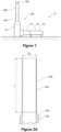
- an exhaust duct assembly for conveying exhaust gases emanating from a combustion zone to atmosphere, according to a first embodiment of the disclosure, is shown diagrammatically in an elevational view.
- the assembly 100 includes an exhaust gas outlet 190 for exhausting exhaust gas into the atmosphere and an acoustic duct portion 200 located upstream of the exhaust gas outlet 190.
- the acoustic duct portion 200 has a peripheral wall 240 as can be seen more clearly in the diagrammatic cross-sectional view of Figure 2A .
- the peripheral wall 240 defines a through-passage arranged and constructed to promote propagation of sound there-through.
- FIG. 1 With the embodiment of the disclosure illustrated in Figures 1 and 2A , there is a plant utilising a gas turbine 10, to which the exhaust duct assembly 100 is connected, as diagrammatically shown in Figure 1 .
- a gas turbine 10 Within the gas turbine 10 is a combustion zone 12.
- Exhaust diffuser ducting 14 links the turbine 10 to a silencer 16.
- High temperature exhaust gases flow from the combustion zone 12 through the exhaust gas diffuser 14 and then through the silencer 16 before entering the above described acoustic duct portion 200, in this case, linked by further intermediate ducting 150.
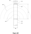
- FIG. 2B a generalized schematic drawing of an exhaust duct assembly shown in Figures 2A is illustrated.
- the exhaust duct assembly of Figure 2B includes an exhaust gas outlet 190 for exhausting exhaust gas into the atmosphere and an acoustic duct portion 200 located upstream of the exhaust gas outlet 190.
- the acoustic duct portion 200 has a peripheral wall that defines a through-passage arranged and constructed to promote propagation of sound there-through. This is illustrated by the dashed semi-circular lines that illustrate hemi-spherical sound waves 300.
- the exhaust duct assembly shown in Figure 2A could be fitted to any hot exhaust system.
- the acoustic duct portion 240 has a length "L" in the flow direction.
- the internal diameter of the acoustic duct portion 200 is "D H ".
- Acoustic duct portions 200 where the ratio L/D H is higher will provide greater noise reduction benefits at locations remote from the plant, such as the downwind location 8 illustrated in Figure 4 , than acoustic duct portions 200 where the ratio L/D H is lower. While a range of L/D H may be used, with the embodiment illustrated, the acoustic duct portion has a length, L, in a flow direction, that is at 400% of average hydraulic diameter, D H , of the through-passage. Or in other words, the ratio L:D H is approximately 4:1.
- the exhaust gas duct 150 is shown to include insulation 155.
- the diameter may be in the range of 3 to 7 metres for instance.
- the insulation may be about 1 metre in thickness and internal baffle silencers may be provided. These baffle silencers can be complimentary to the acoustic duct portion 200 and maybe useful in many applications.
- the ducting has a circular cross-section.
- D is straightforward and will generally equal D H , where D H is the hydraulic diameter of the duct.
- ducts having oval or rectangular cross-sections may be used.
- D H can be calculated and the same principal that acoustic duct portions 200 where the ratio L/D H is higher will provide greater noise reduction benefits will also apply.
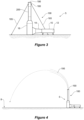
- Figure 4 is a diagrammatic cross-sectional view showing a locality in which an exhaust duct assembly 100 is located.
- Figure 4 illustrates the effect of wind and sound propagation over distance.
- Figure 4 illustrates a high temperature exhaust gas plume 195 being deflected by a crosswind. This will be described in more detail below.
- the acoustic duct portion 200 is located between the exhaust gas duct 150 and the exhaust gas outlet 190.
- the acoustic duct portion 200 includes an acoustic duct wall 240 having a structural portion and a non-structural portion.
- the structural portion which in this embodiment is a perforated metal duct, is arranged and constructed to hold the shape of the acoustic duct portion 200 against loads from gravity, wind, exhaust flow, thermal expansion and others. Generally, the structural portion is also arranged to cope with wind loads.
- the acoustic duct wall 240 also has a non-structural portion which is arranged and constructed to allow at least a range of low frequency sounds to pass there-through. While various materials can be used, in the embodiment of the disclosure illustrated, the non-structural portion is made from any acoustically non-reflective structure, including thin sheet, wire mesh, sheeting with perforated holes and/or woven cloth or glass/mineral fibre batts.
- Figures 9 and 10 illustrate in more detail the structure of the acoustic duct wall 240.
- Figure 9 shows a portion of the structural wall portion 250 which defines a plurality of apertures 255.
- Figure 10 also shows the structural wall portion 250 and its apertures 255, but also shows the non-structural wall portion 260, in the form of wire mesh.
- the exhaust duct assembly 100 shown in Figure 3 is similar to that of the first embodiment of the disclosure shown in Figure 1 .
- a terminal duct portion 180 is provided after the acoustic duct portion 200. Attached to the terminal duct portion 180 are guy-wires 185 that are secured to the ground so as to provide additional lateral stability to the exhaust duct assembly 100.
- FIG. 5 a third embodiment of the disclosure is shown.
- This embodiment includes an air aspirating portion.
- the exhaust gas duct 150 terminates within a mouth 295 of the acoustic duct portion 200.
- the acoustic duct portion 200 is shaped to aspirate or entrain air into the exhaust gas plume as is indicated by arrows A.
- the entrainment of air into the exhaust gas plume lowers its temperature. This assists in reducing the tendency of the plume 195 to refract sound.
- the acoustic duct wall 240 shown in Figure 6A can be constructed in the same way as was described above with reference to Figures 9 and 10 . Alternatively, a different construction may be used.
- the exhaust duct assembly of Figure 6B includes an exhaust gas outlet 190 for exhausting exhaust gas into the atmosphere and an acoustic duct portion 200 located upstream of the exhaust gas outlet 190.
- the acoustic duct portion 200 has a peripheral wall that defines a through-passage arranged and constructed to promote propagation of sound there-through.
- the shape of acoustic duct portion 200 and its positioning relative to the exhaust gas inlet 150 is such that ambient air is aspirate or entrained into the exhaust gas plume as is indicated by arrows A.
- Both of the acoustic duct portions 200 shown in Figures 6A and 6B have a length of "N" in the flow directions.
- the more relevant length for acoustic performance is "L", again measured in the flow direction.
- L/D H a range of L/D H may be used, with the embodiment illustrated, the acoustic duct portion has a length, L, in a flow direction, that is at 400% of the average hydraulic diameter, D H , of the through-passage. Or in other words, the ratio L:D H is approximately 4:1.
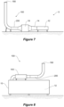
- Figure 7 shows a fourth embodiment of the disclosure.
- This fourth embodiment of the disclosure is similar to the first three embodiments of the disclosure, but where previously the acoustic duct portion 200 was orientated vertically at or towards the terminal end of the exhaust duct assembly 100, with this embodiment, the acoustic duct portion 200 is orientated horizontally.
- this embodiment of the disclosure is similar.
- acoustic duct wall 240 may have the same construction as the acoustic duct portion 200 of the embodiments of the disclosure shown in Figures 1 , 2 , 3 , 5 , 9 and 10 .
- the acoustic duct portion 200 may be placed and supported such that it is not subject to wind loads for instance.
- the entire duct downstream of the silencer 16 may be acoustically porous (not just the duct portion 200 illustrated).
- FIG. 8 A fifth embodiment of the disclosure is shown in Figure 8 .
- the acoustic duct portion is downstream of a combustion zone 12 within a generator set having an internal combustion engine.
Landscapes
- Engineering & Computer Science (AREA)
- Chemical & Material Sciences (AREA)
- Combustion & Propulsion (AREA)
- Mechanical Engineering (AREA)
- General Engineering & Computer Science (AREA)
- Physics & Mathematics (AREA)
- Acoustics & Sound (AREA)
- Multimedia (AREA)
- Exhaust Silencers (AREA)
Claims (8)
- Abgaskanalanordnung (100) zum Ableiten von aus einer Verbrennungszone (12) stammenden Abgasen an die Atmosphäre, wobei die Anordnung (100) umfasst:einen Abgasauslass (190) zum Ablassen von Abgas in die Atmosphäre; undeinen Schallkanalteil (200), der sich stromaufwärts des Abgasauslasses (190) befindet, wobei der Schallkanalteil (200) eine Umfangswand (240) aufweist, die einen Durchgang definiert und eine akustisch poröse Struktur aufweist, und der Schallkanalteil (200) eine Länge (L) in einer Strömungsrichtung aufweist, die mindestens 50 % eines durchschnittlichen hydraulischen Durchmessers (DH) des Durchgangs beträgt, und dadurch gekennzeichnet, dass die genannte Umfangswand (240) zum Fördern der Ausbreitung von Schall (300) durch sie hindurch an die Atmosphäre konstruiert ist.
- Baugruppe nach Anspruch 1, dadurch gekennzeichnet, dass der Schallkanalteil (200) eine Länge (L) in der Strömungsrichtung aufweist, die mindestens 100 % des durchschnittlichen hydraulischen Durchmessers (DH) des Durchgangs beträgt.
- Baugruppe nach Anspruch 2, dadurch gekennzeichnet, dass der Schallkanalteil (200) eine Länge (L) in der Strömungsrichtung aufweist, die mindestens 200 % des durchschnittlichen hydraulischen Durchmessers (DH) des Durchgang beträgt.
- Baugruppe nach Anspruch 1, dadurch gekennzeichnet, dass der Schallkanalteil (200) ein perforiertes Blech beinhaltet.
- Baugruppe nach Anspruch 1, dadurch gekennzeichnet, dass der Schallkanalteil (200) ein Stahlgeflecht beinhaltet.
- Baugruppe nach Anspruch 5, dadurch gekennzeichnet, dass der Schallkanalteil (200) des Stahlgitters ein gewebtes Tuch ist.
- Baugruppe nach Anspruch 1, die einen Luftansaugteil beinhaltet.
- Baugruppe nach Anspruch 7, dadurch gekennzeichnet, dass der Luftansaugteil den Schallkanalteil (200) beinhaltet.
Applications Claiming Priority (2)
| Application Number | Priority Date | Filing Date | Title |
|---|---|---|---|
| AU2018903441A AU2018903441A0 (en) | 2018-09-13 | An exhaust gas assembly | |
| PCT/AU2019/000108 WO2020051623A1 (en) | 2018-09-13 | 2019-09-13 | An exhaust gas assembly |
Publications (4)
| Publication Number | Publication Date |
|---|---|
| EP3850197A1 EP3850197A1 (de) | 2021-07-21 |
| EP3850197A4 EP3850197A4 (de) | 2022-04-06 |
| EP3850197B1 true EP3850197B1 (de) | 2025-02-26 |
| EP3850197C0 EP3850197C0 (de) | 2025-02-26 |
Family
ID=69776444
Family Applications (1)
| Application Number | Title | Priority Date | Filing Date |
|---|---|---|---|
| EP19861090.9A Active EP3850197B1 (de) | 2018-09-13 | 2019-09-13 | Abgasanordnung |
Country Status (5)
| Country | Link |
|---|---|
| US (2) | US12116913B2 (de) |
| EP (1) | EP3850197B1 (de) |
| JP (1) | JP7525906B2 (de) |
| AU (1) | AU2019337730B2 (de) |
| WO (1) | WO2020051623A1 (de) |
Families Citing this family (2)
| Publication number | Priority date | Publication date | Assignee | Title |
|---|---|---|---|---|
| EP3850197B1 (de) * | 2018-09-13 | 2025-02-26 | The University of Adelaide | Abgasanordnung |
| US20250250922A1 (en) * | 2024-02-01 | 2025-08-07 | Solar Turbines Incorporated | Sound-attenuating devices |
Family Cites Families (30)
| Publication number | Priority date | Publication date | Assignee | Title |
|---|---|---|---|---|
| US2934889A (en) * | 1956-02-14 | 1960-05-03 | United Aircraft Corp | Noise abatement means |
| US2936846A (en) * | 1956-04-30 | 1960-05-17 | United Aircraft Corp | Ground exhaust noise suppressors |
| US3011584A (en) * | 1957-12-16 | 1961-12-05 | Koppers Co Inc | Sound attenuating device |
| US3690606A (en) | 1968-05-27 | 1972-09-12 | Pall Corp | Anisometric compressed and bonded multilayer knitted wire mesh composites |
| US3715009A (en) | 1970-08-17 | 1973-02-06 | Gen Acoustics Corp | Jet engine noise suppression system |
| RO53910A2 (de) * | 1970-10-26 | 1973-09-20 | ||
| RO54896A2 (de) * | 1971-12-13 | 1973-09-20 | ||
| RO62594A2 (ro) | 1975-06-12 | 1975-08-01 | Inst Pentru Creatie Stintific | Procedeu si dispozitiv pentru atenuarea zgomotului radiat de jeturile de gaze |
| US4105089A (en) * | 1975-11-24 | 1978-08-08 | Judd Frederick V H | Flow distributor for gas turbine silencers |
| JPS585051Y2 (ja) | 1978-07-21 | 1983-01-28 | カルソニックカンセイ株式会社 | 排気導管 |
| US4244441A (en) * | 1979-07-31 | 1981-01-13 | The Garrett Corporation | Broad band acoustic attenuator |
| US5471020A (en) * | 1993-08-30 | 1995-11-28 | Hatch Associates Ltd. | Modal silencer |
| WO1995030393A1 (en) * | 1994-05-10 | 1995-11-16 | Noise Cancellation Technologies, Inc. | Active noise cancelling muffler |
| US5837890A (en) * | 1994-12-12 | 1998-11-17 | Aero Systems Engineering, Inc. | Jet engine test cell structure |
| US5962821A (en) | 1995-01-27 | 1999-10-05 | Iannetti; Francesco E. | Internal combustion engine noise reduction apparatus |
| JP3310931B2 (ja) * | 1997-09-25 | 2002-08-05 | 三菱重工業株式会社 | ガスタービン排気煙道 |
| US6612106B2 (en) | 2000-05-05 | 2003-09-02 | The Boeing Company | Segmented mixing device having chevrons for exhaust noise reduction in jet engines |
| CA2456249C (en) * | 2004-01-26 | 2012-04-10 | Plasticair Inc. | Upblast fan nozzle with wind deflecting panels |
| WO2008018821A1 (en) * | 2006-08-11 | 2008-02-14 | Volvo Construction Equipment Ab | A device for attenuating and/or directing sound, and a work machine |
| KR101388625B1 (ko) * | 2007-08-31 | 2014-04-24 | 테네코 오토모티브 오퍼레이팅 컴파니 인코포레이티드 | 냉각특징을 갖는 차량용 배기가스 공명기 |
| DE102007055401B4 (de) * | 2007-11-19 | 2010-04-15 | Festo Ag & Co. Kg | Abluftschalldämpfer für pneumatische Einrichtungen |
| TR200800740A2 (tr) | 2008-02-06 | 2008-06-23 | Özel Zafer | İçten yanmalı motor eksozunda vakum yaratan susturucu. |
| US8166752B2 (en) * | 2008-11-26 | 2012-05-01 | GM Global Technology Operations LLC | Apparatus and method for cooling an exhaust gas |
| US8087491B2 (en) * | 2010-01-08 | 2012-01-03 | General Electric Company | Vane type silencers in elbow for gas turbine |
| US9897111B2 (en) | 2011-05-20 | 2018-02-20 | Dyna-Tech Sales Corporation | Aspirating induction nozzle with flow transition |
| US8974272B2 (en) * | 2011-05-20 | 2015-03-10 | Dyna-Tech Sales Corporation | Aspirating induction nozzle |
| JP6071664B2 (ja) * | 2012-03-14 | 2017-02-01 | 三菱重工業株式会社 | 排気煙道 |
| DE102013014455B4 (de) * | 2013-08-30 | 2016-10-06 | Eberspächer Exhaust Technology GmbH & Co. KG | System zur Beeinflussung von Abgasgeräuschen |
| KR20170052629A (ko) | 2014-09-09 | 2017-05-12 | 쓰리엠 이노베이티브 프로퍼티즈 컴파니 | 음향 장치 |
| EP3850197B1 (de) * | 2018-09-13 | 2025-02-26 | The University of Adelaide | Abgasanordnung |
-
2019
- 2019-09-13 EP EP19861090.9A patent/EP3850197B1/de active Active
- 2019-09-13 AU AU2019337730A patent/AU2019337730B2/en active Active
- 2019-09-13 JP JP2021538865A patent/JP7525906B2/ja active Active
- 2019-09-13 WO PCT/AU2019/000108 patent/WO2020051623A1/en not_active Ceased
- 2019-09-13 US US17/276,047 patent/US12116913B2/en active Active
-
2024
- 2024-09-11 US US18/882,494 patent/US12454902B2/en active Active
Also Published As
| Publication number | Publication date |
|---|---|
| US20250003359A1 (en) | 2025-01-02 |
| US12116913B2 (en) | 2024-10-15 |
| US12454902B2 (en) | 2025-10-28 |
| AU2019337730B2 (en) | 2025-07-03 |
| WO2020051623A1 (en) | 2020-03-19 |
| JP7525906B2 (ja) | 2024-07-31 |
| US20220042431A1 (en) | 2022-02-10 |
| AU2019337730A1 (en) | 2021-05-06 |
| EP3850197A4 (de) | 2022-04-06 |
| EP3850197A1 (de) | 2021-07-21 |
| JP2022500594A (ja) | 2022-01-04 |
| EP3850197C0 (de) | 2025-02-26 |
Similar Documents
| Publication | Publication Date | Title |
|---|---|---|
| US12454902B2 (en) | Exhaust gas assembly | |
| US3196977A (en) | Sound attenuation control means including diffuser for high velocity streams | |
| JP5738524B2 (ja) | 音響減衰システム及び方法 | |
| US6968923B2 (en) | Reduced noise valve stack connection | |
| KR100924958B1 (ko) | 공명형 스플릿터를 구비한 공조용 덕트 소음기 | |
| CS203048B2 (en) | Device for damping the noise brought about by releasing the gases in the atmosphere | |
| CN106015818A (zh) | 一种消声节能管道 | |
| CA2976944A1 (en) | Turbomachine test bench with active noise control | |
| US4211303A (en) | Sound absorbing device | |
| SE522546C2 (sv) | Anordning för dämpning av resonans i en rörledning | |
| CN210516212U (zh) | 一种多级节流降压阻抗复合型消声器装置 | |
| JP2005220871A (ja) | 消音器 | |
| CN103671280B (zh) | 复合烟囱消声器 | |
| CN119333268A (zh) | 音色缩放排气系统 | |
| CN203242331U (zh) | 一种低噪音锅炉烟囱 | |
| US4211302A (en) | Sound absorbing device | |
| RU200098U1 (ru) | Глушитель шума выбросов пара | |
| GB2204916A (en) | Gaseous flow silencer | |
| CN202791129U (zh) | 一种石化装置管线金属隔声罩 | |
| Tupov | Noise reduction from air intakes of compressors and blower fans | |
| RU22227U1 (ru) | Шумоглушитель в отводе | |
| CN208474764U (zh) | 一种用于泄放含尘油气的可拆卸式消声器 | |
| JP2017057850A (ja) | 消音要素及びカプラを有するサイレンサダクト | |
| JP4731829B2 (ja) | 消音装置 | |
| CN114646080A (zh) | 抽油烟机 |
Legal Events
| Date | Code | Title | Description |
|---|---|---|---|
| STAA | Information on the status of an ep patent application or granted ep patent |
Free format text: STATUS: THE INTERNATIONAL PUBLICATION HAS BEEN MADE |
|
| PUAI | Public reference made under article 153(3) epc to a published international application that has entered the european phase |
Free format text: ORIGINAL CODE: 0009012 |
|
| STAA | Information on the status of an ep patent application or granted ep patent |
Free format text: STATUS: REQUEST FOR EXAMINATION WAS MADE |
|
| 17P | Request for examination filed |
Effective date: 20210326 |
|
| AK | Designated contracting states |
Kind code of ref document: A1 Designated state(s): AL AT BE BG CH CY CZ DE DK EE ES FI FR GB GR HR HU IE IS IT LI LT LU LV MC MK MT NL NO PL PT RO RS SE SI SK SM TR |
|
| DAV | Request for validation of the european patent (deleted) | ||
| DAX | Request for extension of the european patent (deleted) | ||
| A4 | Supplementary search report drawn up and despatched |
Effective date: 20220307 |
|
| RIC1 | Information provided on ipc code assigned before grant |
Ipc: F01N 13/08 20100101ALI20220301BHEP Ipc: F02C 7/24 20060101ALI20220301BHEP Ipc: F01N 13/16 20100101ALI20220301BHEP Ipc: F01N 1/24 20060101ALI20220301BHEP Ipc: F01N 1/10 20060101ALI20220301BHEP Ipc: F01N 1/08 20060101AFI20220301BHEP |
|
| STAA | Information on the status of an ep patent application or granted ep patent |
Free format text: STATUS: EXAMINATION IS IN PROGRESS |
|
| 17Q | First examination report despatched |
Effective date: 20230503 |
|
| GRAP | Despatch of communication of intention to grant a patent |
Free format text: ORIGINAL CODE: EPIDOSNIGR1 |
|
| STAA | Information on the status of an ep patent application or granted ep patent |
Free format text: STATUS: GRANT OF PATENT IS INTENDED |
|
| INTG | Intention to grant announced |
Effective date: 20241028 |
|
| GRAS | Grant fee paid |
Free format text: ORIGINAL CODE: EPIDOSNIGR3 |
|
| GRAA | (expected) grant |
Free format text: ORIGINAL CODE: 0009210 |
|
| STAA | Information on the status of an ep patent application or granted ep patent |
Free format text: STATUS: THE PATENT HAS BEEN GRANTED |
|
| AK | Designated contracting states |
Kind code of ref document: B1 Designated state(s): AL AT BE BG CH CY CZ DE DK EE ES FI FR GB GR HR HU IE IS IT LI LT LU LV MC MK MT NL NO PL PT RO RS SE SI SK SM TR |
|
| REG | Reference to a national code |
Ref country code: GB Ref legal event code: FG4D |
|
| REG | Reference to a national code |
Ref country code: CH Ref legal event code: EP |
|
| REG | Reference to a national code |
Ref country code: DE Ref legal event code: R096 Ref document number: 602019066624 Country of ref document: DE |
|
| REG | Reference to a national code |
Ref country code: IE Ref legal event code: FG4D |
|
| U01 | Request for unitary effect filed |
Effective date: 20250312 |
|
| U07 | Unitary effect registered |
Designated state(s): AT BE BG DE DK EE FI FR IT LT LU LV MT NL PT RO SE SI Effective date: 20250318 |
|
| PG25 | Lapsed in a contracting state [announced via postgrant information from national office to epo] |
Ref country code: RS Free format text: LAPSE BECAUSE OF FAILURE TO SUBMIT A TRANSLATION OF THE DESCRIPTION OR TO PAY THE FEE WITHIN THE PRESCRIBED TIME-LIMIT Effective date: 20250526 |
|
| PG25 | Lapsed in a contracting state [announced via postgrant information from national office to epo] |
Ref country code: PL Free format text: LAPSE BECAUSE OF FAILURE TO SUBMIT A TRANSLATION OF THE DESCRIPTION OR TO PAY THE FEE WITHIN THE PRESCRIBED TIME-LIMIT Effective date: 20250226 |
|
| PG25 | Lapsed in a contracting state [announced via postgrant information from national office to epo] |
Ref country code: ES Free format text: LAPSE BECAUSE OF FAILURE TO SUBMIT A TRANSLATION OF THE DESCRIPTION OR TO PAY THE FEE WITHIN THE PRESCRIBED TIME-LIMIT Effective date: 20250226 |
|
| PG25 | Lapsed in a contracting state [announced via postgrant information from national office to epo] |
Ref country code: IS Free format text: LAPSE BECAUSE OF FAILURE TO SUBMIT A TRANSLATION OF THE DESCRIPTION OR TO PAY THE FEE WITHIN THE PRESCRIBED TIME-LIMIT Effective date: 20250626 Ref country code: NO Free format text: LAPSE BECAUSE OF FAILURE TO SUBMIT A TRANSLATION OF THE DESCRIPTION OR TO PAY THE FEE WITHIN THE PRESCRIBED TIME-LIMIT Effective date: 20250526 |
|
| PG25 | Lapsed in a contracting state [announced via postgrant information from national office to epo] |
Ref country code: HR Free format text: LAPSE BECAUSE OF FAILURE TO SUBMIT A TRANSLATION OF THE DESCRIPTION OR TO PAY THE FEE WITHIN THE PRESCRIBED TIME-LIMIT Effective date: 20250226 |
|
| PG25 | Lapsed in a contracting state [announced via postgrant information from national office to epo] |
Ref country code: GR Free format text: LAPSE BECAUSE OF FAILURE TO SUBMIT A TRANSLATION OF THE DESCRIPTION OR TO PAY THE FEE WITHIN THE PRESCRIBED TIME-LIMIT Effective date: 20250527 |
|
| U20 | Renewal fee for the european patent with unitary effect paid |
Year of fee payment: 7 Effective date: 20250630 |
|
| PG25 | Lapsed in a contracting state [announced via postgrant information from national office to epo] |
Ref country code: SM Free format text: LAPSE BECAUSE OF FAILURE TO SUBMIT A TRANSLATION OF THE DESCRIPTION OR TO PAY THE FEE WITHIN THE PRESCRIBED TIME-LIMIT Effective date: 20250226 |
|
| PG25 | Lapsed in a contracting state [announced via postgrant information from national office to epo] |
Ref country code: CZ Free format text: LAPSE BECAUSE OF FAILURE TO SUBMIT A TRANSLATION OF THE DESCRIPTION OR TO PAY THE FEE WITHIN THE PRESCRIBED TIME-LIMIT Effective date: 20250226 |
|
| PG25 | Lapsed in a contracting state [announced via postgrant information from national office to epo] |
Ref country code: SK Free format text: LAPSE BECAUSE OF FAILURE TO SUBMIT A TRANSLATION OF THE DESCRIPTION OR TO PAY THE FEE WITHIN THE PRESCRIBED TIME-LIMIT Effective date: 20250226 |