EP3850197B1 - An exhaust gas assembly - Google Patents
An exhaust gas assembly Download PDFInfo
- Publication number
- EP3850197B1 EP3850197B1 EP19861090.9A EP19861090A EP3850197B1 EP 3850197 B1 EP3850197 B1 EP 3850197B1 EP 19861090 A EP19861090 A EP 19861090A EP 3850197 B1 EP3850197 B1 EP 3850197B1
- Authority
- EP
- European Patent Office
- Prior art keywords
- exhaust
- duct portion
- acoustic duct
- assembly
- acoustic
- Prior art date
- Legal status (The legal status is an assumption and is not a legal conclusion. Google has not performed a legal analysis and makes no representation as to the accuracy of the status listed.)
- Active
Links
Images


Classifications
-
- F—MECHANICAL ENGINEERING; LIGHTING; HEATING; WEAPONS; BLASTING
- F01—MACHINES OR ENGINES IN GENERAL; ENGINE PLANTS IN GENERAL; STEAM ENGINES
- F01N—GAS-FLOW SILENCERS OR EXHAUST APPARATUS FOR MACHINES OR ENGINES IN GENERAL; GAS-FLOW SILENCERS OR EXHAUST APPARATUS FOR INTERNAL-COMBUSTION ENGINES
- F01N1/00—Silencing apparatus characterised by method of silencing
- F01N1/08—Silencing apparatus characterised by method of silencing by reducing exhaust energy by throttling or whirling
- F01N1/082—Silencing apparatus characterised by method of silencing by reducing exhaust energy by throttling or whirling by passing the exhaust gases through porous members
-
- F—MECHANICAL ENGINEERING; LIGHTING; HEATING; WEAPONS; BLASTING
- F01—MACHINES OR ENGINES IN GENERAL; ENGINE PLANTS IN GENERAL; STEAM ENGINES
- F01D—NON-POSITIVE DISPLACEMENT MACHINES OR ENGINES, e.g. STEAM TURBINES
- F01D25/00—Component parts, details, or accessories, not provided for in, or of interest apart from, other groups
- F01D25/30—Exhaust heads, chambers, or the like
-
- F—MECHANICAL ENGINEERING; LIGHTING; HEATING; WEAPONS; BLASTING
- F01—MACHINES OR ENGINES IN GENERAL; ENGINE PLANTS IN GENERAL; STEAM ENGINES
- F01N—GAS-FLOW SILENCERS OR EXHAUST APPARATUS FOR MACHINES OR ENGINES IN GENERAL; GAS-FLOW SILENCERS OR EXHAUST APPARATUS FOR INTERNAL-COMBUSTION ENGINES
- F01N1/00—Silencing apparatus characterised by method of silencing
- F01N1/08—Silencing apparatus characterised by method of silencing by reducing exhaust energy by throttling or whirling
- F01N1/085—Silencing apparatus characterised by method of silencing by reducing exhaust energy by throttling or whirling throttling exhaust gas flow using a central core in a flow passage
-
- F—MECHANICAL ENGINEERING; LIGHTING; HEATING; WEAPONS; BLASTING
- F01—MACHINES OR ENGINES IN GENERAL; ENGINE PLANTS IN GENERAL; STEAM ENGINES
- F01N—GAS-FLOW SILENCERS OR EXHAUST APPARATUS FOR MACHINES OR ENGINES IN GENERAL; GAS-FLOW SILENCERS OR EXHAUST APPARATUS FOR INTERNAL-COMBUSTION ENGINES
- F01N1/00—Silencing apparatus characterised by method of silencing
- F01N1/24—Silencing apparatus characterised by method of silencing by using sound-absorbing materials
-
- F—MECHANICAL ENGINEERING; LIGHTING; HEATING; WEAPONS; BLASTING
- F01—MACHINES OR ENGINES IN GENERAL; ENGINE PLANTS IN GENERAL; STEAM ENGINES
- F01N—GAS-FLOW SILENCERS OR EXHAUST APPARATUS FOR MACHINES OR ENGINES IN GENERAL; GAS-FLOW SILENCERS OR EXHAUST APPARATUS FOR INTERNAL-COMBUSTION ENGINES
- F01N13/00—Exhaust or silencing apparatus characterised by constructional features
- F01N13/08—Other arrangements or adaptations of exhaust conduits
- F01N13/082—Other arrangements or adaptations of exhaust conduits of tailpipe, e.g. with means for mixing air with exhaust for exhaust cooling, dilution or evacuation
-
- F—MECHANICAL ENGINEERING; LIGHTING; HEATING; WEAPONS; BLASTING
- F01—MACHINES OR ENGINES IN GENERAL; ENGINE PLANTS IN GENERAL; STEAM ENGINES
- F01N—GAS-FLOW SILENCERS OR EXHAUST APPARATUS FOR MACHINES OR ENGINES IN GENERAL; GAS-FLOW SILENCERS OR EXHAUST APPARATUS FOR INTERNAL-COMBUSTION ENGINES
- F01N13/00—Exhaust or silencing apparatus characterised by constructional features
- F01N13/20—Exhaust or silencing apparatus characterised by constructional features having flared outlets, e.g. of fish-tail shape
-
- F—MECHANICAL ENGINEERING; LIGHTING; HEATING; WEAPONS; BLASTING
- F02—COMBUSTION ENGINES; HOT-GAS OR COMBUSTION-PRODUCT ENGINE PLANTS
- F02C—GAS-TURBINE PLANTS; AIR INTAKES FOR JET-PROPULSION PLANTS; CONTROLLING FUEL SUPPLY IN AIR-BREATHING JET-PROPULSION PLANTS
- F02C7/00—Features, components parts, details or accessories, not provided for in, or of interest apart form groups F02C1/00 - F02C6/00; Air intakes for jet-propulsion plants
- F02C7/24—Heat or noise insulation
-
- G—PHYSICS
- G10—MUSICAL INSTRUMENTS; ACOUSTICS
- G10K—SOUND-PRODUCING DEVICES; METHODS OR DEVICES FOR PROTECTING AGAINST, OR FOR DAMPING, NOISE OR OTHER ACOUSTIC WAVES IN GENERAL; ACOUSTICS NOT OTHERWISE PROVIDED FOR
- G10K11/00—Methods or devices for transmitting, conducting or directing sound in general; Methods or devices for protecting against, or for damping, noise or other acoustic waves in general
- G10K11/16—Methods or devices for protecting against, or for damping, noise or other acoustic waves in general
- G10K11/162—Selection of materials
-
- F—MECHANICAL ENGINEERING; LIGHTING; HEATING; WEAPONS; BLASTING
- F01—MACHINES OR ENGINES IN GENERAL; ENGINE PLANTS IN GENERAL; STEAM ENGINES
- F01N—GAS-FLOW SILENCERS OR EXHAUST APPARATUS FOR MACHINES OR ENGINES IN GENERAL; GAS-FLOW SILENCERS OR EXHAUST APPARATUS FOR INTERNAL-COMBUSTION ENGINES
- F01N1/00—Silencing apparatus characterised by method of silencing
- F01N1/08—Silencing apparatus characterised by method of silencing by reducing exhaust energy by throttling or whirling
- F01N1/10—Silencing apparatus characterised by method of silencing by reducing exhaust energy by throttling or whirling in combination with sound-absorbing materials
-
- F—MECHANICAL ENGINEERING; LIGHTING; HEATING; WEAPONS; BLASTING
- F01—MACHINES OR ENGINES IN GENERAL; ENGINE PLANTS IN GENERAL; STEAM ENGINES
- F01N—GAS-FLOW SILENCERS OR EXHAUST APPARATUS FOR MACHINES OR ENGINES IN GENERAL; GAS-FLOW SILENCERS OR EXHAUST APPARATUS FOR INTERNAL-COMBUSTION ENGINES
- F01N2260/00—Exhaust treating devices having provisions not otherwise provided for
- F01N2260/16—Exhaust treating devices having provisions not otherwise provided for for reducing exhaust flow pulsations
-
- F—MECHANICAL ENGINEERING; LIGHTING; HEATING; WEAPONS; BLASTING
- F01—MACHINES OR ENGINES IN GENERAL; ENGINE PLANTS IN GENERAL; STEAM ENGINES
- F01N—GAS-FLOW SILENCERS OR EXHAUST APPARATUS FOR MACHINES OR ENGINES IN GENERAL; GAS-FLOW SILENCERS OR EXHAUST APPARATUS FOR INTERNAL-COMBUSTION ENGINES
- F01N2310/00—Selection of sound absorbing or insulating material
- F01N2310/04—Metallic wool, e.g. steel wool, copper wool or the like
-
- F—MECHANICAL ENGINEERING; LIGHTING; HEATING; WEAPONS; BLASTING
- F01—MACHINES OR ENGINES IN GENERAL; ENGINE PLANTS IN GENERAL; STEAM ENGINES
- F01N—GAS-FLOW SILENCERS OR EXHAUST APPARATUS FOR MACHINES OR ENGINES IN GENERAL; GAS-FLOW SILENCERS OR EXHAUST APPARATUS FOR INTERNAL-COMBUSTION ENGINES
- F01N2310/00—Selection of sound absorbing or insulating material
- F01N2310/14—Wire mesh fabric, woven glass cloth or the like
-
- F—MECHANICAL ENGINEERING; LIGHTING; HEATING; WEAPONS; BLASTING
- F01—MACHINES OR ENGINES IN GENERAL; ENGINE PLANTS IN GENERAL; STEAM ENGINES
- F01N—GAS-FLOW SILENCERS OR EXHAUST APPARATUS FOR MACHINES OR ENGINES IN GENERAL; GAS-FLOW SILENCERS OR EXHAUST APPARATUS FOR INTERNAL-COMBUSTION ENGINES
- F01N2340/00—Dimensional characteristics of the exhaust system, e.g. length, diameter or volume of the exhaust apparatus; Spatial arrangements of exhaust apparatuses
-
- F—MECHANICAL ENGINEERING; LIGHTING; HEATING; WEAPONS; BLASTING
- F01—MACHINES OR ENGINES IN GENERAL; ENGINE PLANTS IN GENERAL; STEAM ENGINES
- F01N—GAS-FLOW SILENCERS OR EXHAUST APPARATUS FOR MACHINES OR ENGINES IN GENERAL; GAS-FLOW SILENCERS OR EXHAUST APPARATUS FOR INTERNAL-COMBUSTION ENGINES
- F01N2470/00—Structure or shape of exhaust gas passages, pipes or tubes
- F01N2470/02—Tubes being perforated
- F01N2470/04—Tubes being perforated characterised by shape, disposition or dimensions of apertures
-
- F—MECHANICAL ENGINEERING; LIGHTING; HEATING; WEAPONS; BLASTING
- F01—MACHINES OR ENGINES IN GENERAL; ENGINE PLANTS IN GENERAL; STEAM ENGINES
- F01N—GAS-FLOW SILENCERS OR EXHAUST APPARATUS FOR MACHINES OR ENGINES IN GENERAL; GAS-FLOW SILENCERS OR EXHAUST APPARATUS FOR INTERNAL-COMBUSTION ENGINES
- F01N2470/00—Structure or shape of exhaust gas passages, pipes or tubes
- F01N2470/18—Structure or shape of exhaust gas passages, pipes or tubes the axis of inlet or outlet tubes being other than the longitudinal axis of apparatus
-
- F—MECHANICAL ENGINEERING; LIGHTING; HEATING; WEAPONS; BLASTING
- F01—MACHINES OR ENGINES IN GENERAL; ENGINE PLANTS IN GENERAL; STEAM ENGINES
- F01N—GAS-FLOW SILENCERS OR EXHAUST APPARATUS FOR MACHINES OR ENGINES IN GENERAL; GAS-FLOW SILENCERS OR EXHAUST APPARATUS FOR INTERNAL-COMBUSTION ENGINES
- F01N2470/00—Structure or shape of exhaust gas passages, pipes or tubes
- F01N2470/20—Dimensional characteristics of tubes, e.g. length, diameter
-
- F—MECHANICAL ENGINEERING; LIGHTING; HEATING; WEAPONS; BLASTING
- F01—MACHINES OR ENGINES IN GENERAL; ENGINE PLANTS IN GENERAL; STEAM ENGINES
- F01N—GAS-FLOW SILENCERS OR EXHAUST APPARATUS FOR MACHINES OR ENGINES IN GENERAL; GAS-FLOW SILENCERS OR EXHAUST APPARATUS FOR INTERNAL-COMBUSTION ENGINES
- F01N2470/00—Structure or shape of exhaust gas passages, pipes or tubes
- F01N2470/30—Tubes with restrictions, i.e. venturi or the like, e.g. for sucking air or measuring mass flow
-
- F—MECHANICAL ENGINEERING; LIGHTING; HEATING; WEAPONS; BLASTING
- F01—MACHINES OR ENGINES IN GENERAL; ENGINE PLANTS IN GENERAL; STEAM ENGINES
- F01N—GAS-FLOW SILENCERS OR EXHAUST APPARATUS FOR MACHINES OR ENGINES IN GENERAL; GAS-FLOW SILENCERS OR EXHAUST APPARATUS FOR INTERNAL-COMBUSTION ENGINES
- F01N2590/00—Exhaust or silencing apparatus adapted to particular use, e.g. for military applications, airplanes, submarines
- F01N2590/10—Exhaust or silencing apparatus adapted to particular use, e.g. for military applications, airplanes, submarines for stationary applications
-
- F—MECHANICAL ENGINEERING; LIGHTING; HEATING; WEAPONS; BLASTING
- F05—INDEXING SCHEMES RELATING TO ENGINES OR PUMPS IN VARIOUS SUBCLASSES OF CLASSES F01-F04
- F05D—INDEXING SCHEME FOR ASPECTS RELATING TO NON-POSITIVE-DISPLACEMENT MACHINES OR ENGINES, GAS-TURBINES OR JET-PROPULSION PLANTS
- F05D2260/00—Function
- F05D2260/96—Preventing, counteracting or reducing vibration or noise
Definitions
- the present disclosure relates to noise control.
- the present disclosure relates to the control of noise emanating from hot exhaust systems.
- the acoustic wavelength can be as large as 23m.
- industrial silencers are used. These silencers are lined with sound absorptive material that is typically about 0.5 m thick (only about 1/45th of the wavelength), and hence do not provide good sound attenuation at low frequencies. This can result in loud 'rumbling' or other low frequency sound effects being perceived at distances remote from the power plant.
- a further challenge with controlling noise emanating from hot exhaust systems is that high temperature gases have reduced viscosity, making sound absorption more difficult.
- a still further challenge with controlling noise emanating from hot exhaust systems is that high temperature gases have increased flow rates which has a big impact on self-noise (sound generated by the flow of the high speed gas through the exhaust system).
- problematic noise control situations include gas-fired power plants, especially single-cycle plants. This is because the higher exhaust temperatures in single-cycle plants (550-600°C compared with 80-200°C for combined-cycles) reduces the efficacy of traditional silencers. This presents a challenge for acoustic control.
- problematic noise control situations include internal combustion engine powered generators used for commercial power generation, and calciners used in cement production.
- US3794137 discloses a device for attenuating the noise generated by the expansion of gases into the atmosphere.
- the device includes sections having a sound absorbing coating.
- WO2009/099399 discloses a vacuum creating exhaust muffler for internal combustion engines by reducing the back pressure at the exhaust of the internal combustion engine below the atmospheric pressure and keeping it at a constant value independently of the engine operating conditions.
- US4113048 discloses a device for attenuating the noise radiated by gas jets by causing the sound to pass from the annular section of the jet to a narrow annular section of a nozzle slot. Sound wave diffraction takes place on emergence from the slot by using a baffle and reflection of the sound onto a sound absorption lining.
- US2936846 discloses a ground exhaust noise suppressor that reduces noise by discharging the jet engine exhaust through a multiplicity of small holes or nozzles.
- US2009/057056 discloses a vehicular exhaust resonator includes an exhaust inlet conduit which narrows down in a manner so as to define a venturi effect region. Air entrainment apertures are provided in the housing of the resonator. Due to the venturi effect inside the inlet conduit, a pressure drop is created that pulls air from the outside into the air inlet chamber and then into an outlet conduit of the resonator.
- US5962821 discloses an internal combustion engine noise reduction apparatus that includes sound absorbing layers disposed within the apparatus housing.
- WO2016/040431 discloses an acoustic device including a chamber that has a wall partitioning an expansion chamber into a central chamber and a peripheral chamber.
- the internal partition wall has a plurality of apertures defined through the same.
- an exhaust duct assembly for conveying exhaust gases emanating from a combustion zone to atmosphere, the assembly including: an exhaust gas outlet for exhausting exhaust gas into the atmosphere; and an acoustic duct portion located upstream of the exhaust gas outlet, the acoustic duct portion having a peripheral wall defining a through-passage and including an acoustically porous structure, and the acoustic duct portion has a length (L) in a flow direction that is at least 50% of an average hydraulic diameter (D H ) of the through-passage and characterised in that said peripheral wall is constructed to promote propagation of sound there-through to atmosphere.
- the acoustic duct portion has a length in the flow direction that is at least 100% of the average hydraulic diameter of the through-passage. In one form, the acoustic duct portion has a length in the flow direction that is at least 200% of the average hydraulic diameter of the through-passage.
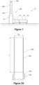
- an exhaust duct assembly for conveying exhaust gases emanating from a combustion zone to atmosphere, according to a first embodiment of the disclosure, is shown diagrammatically in an elevational view.
- the assembly 100 includes an exhaust gas outlet 190 for exhausting exhaust gas into the atmosphere and an acoustic duct portion 200 located upstream of the exhaust gas outlet 190.
- the acoustic duct portion 200 has a peripheral wall 240 as can be seen more clearly in the diagrammatic cross-sectional view of Figure 2A .
- the peripheral wall 240 defines a through-passage arranged and constructed to promote propagation of sound there-through.
- FIG. 1 With the embodiment of the disclosure illustrated in Figures 1 and 2A , there is a plant utilising a gas turbine 10, to which the exhaust duct assembly 100 is connected, as diagrammatically shown in Figure 1 .
- a gas turbine 10 Within the gas turbine 10 is a combustion zone 12.
- Exhaust diffuser ducting 14 links the turbine 10 to a silencer 16.
- High temperature exhaust gases flow from the combustion zone 12 through the exhaust gas diffuser 14 and then through the silencer 16 before entering the above described acoustic duct portion 200, in this case, linked by further intermediate ducting 150.
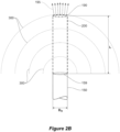
- FIG. 2B a generalized schematic drawing of an exhaust duct assembly shown in Figures 2A is illustrated.
- the exhaust duct assembly of Figure 2B includes an exhaust gas outlet 190 for exhausting exhaust gas into the atmosphere and an acoustic duct portion 200 located upstream of the exhaust gas outlet 190.
- the acoustic duct portion 200 has a peripheral wall that defines a through-passage arranged and constructed to promote propagation of sound there-through. This is illustrated by the dashed semi-circular lines that illustrate hemi-spherical sound waves 300.
- the exhaust duct assembly shown in Figure 2A could be fitted to any hot exhaust system.
- the acoustic duct portion 240 has a length "L" in the flow direction.
- the internal diameter of the acoustic duct portion 200 is "D H ".
- Acoustic duct portions 200 where the ratio L/D H is higher will provide greater noise reduction benefits at locations remote from the plant, such as the downwind location 8 illustrated in Figure 4 , than acoustic duct portions 200 where the ratio L/D H is lower. While a range of L/D H may be used, with the embodiment illustrated, the acoustic duct portion has a length, L, in a flow direction, that is at 400% of average hydraulic diameter, D H , of the through-passage. Or in other words, the ratio L:D H is approximately 4:1.
- the exhaust gas duct 150 is shown to include insulation 155.
- the diameter may be in the range of 3 to 7 metres for instance.
- the insulation may be about 1 metre in thickness and internal baffle silencers may be provided. These baffle silencers can be complimentary to the acoustic duct portion 200 and maybe useful in many applications.
- the ducting has a circular cross-section.
- D is straightforward and will generally equal D H , where D H is the hydraulic diameter of the duct.
- ducts having oval or rectangular cross-sections may be used.
- D H can be calculated and the same principal that acoustic duct portions 200 where the ratio L/D H is higher will provide greater noise reduction benefits will also apply.
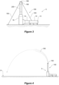
- Figure 4 is a diagrammatic cross-sectional view showing a locality in which an exhaust duct assembly 100 is located.
- Figure 4 illustrates the effect of wind and sound propagation over distance.
- Figure 4 illustrates a high temperature exhaust gas plume 195 being deflected by a crosswind. This will be described in more detail below.
- the acoustic duct portion 200 is located between the exhaust gas duct 150 and the exhaust gas outlet 190.
- the acoustic duct portion 200 includes an acoustic duct wall 240 having a structural portion and a non-structural portion.
- the structural portion which in this embodiment is a perforated metal duct, is arranged and constructed to hold the shape of the acoustic duct portion 200 against loads from gravity, wind, exhaust flow, thermal expansion and others. Generally, the structural portion is also arranged to cope with wind loads.
- the acoustic duct wall 240 also has a non-structural portion which is arranged and constructed to allow at least a range of low frequency sounds to pass there-through. While various materials can be used, in the embodiment of the disclosure illustrated, the non-structural portion is made from any acoustically non-reflective structure, including thin sheet, wire mesh, sheeting with perforated holes and/or woven cloth or glass/mineral fibre batts.
- Figures 9 and 10 illustrate in more detail the structure of the acoustic duct wall 240.
- Figure 9 shows a portion of the structural wall portion 250 which defines a plurality of apertures 255.
- Figure 10 also shows the structural wall portion 250 and its apertures 255, but also shows the non-structural wall portion 260, in the form of wire mesh.
- the exhaust duct assembly 100 shown in Figure 3 is similar to that of the first embodiment of the disclosure shown in Figure 1 .
- a terminal duct portion 180 is provided after the acoustic duct portion 200. Attached to the terminal duct portion 180 are guy-wires 185 that are secured to the ground so as to provide additional lateral stability to the exhaust duct assembly 100.
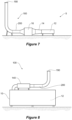
- FIG. 5 a third embodiment of the disclosure is shown.
- This embodiment includes an air aspirating portion.
- the exhaust gas duct 150 terminates within a mouth 295 of the acoustic duct portion 200.
- the acoustic duct portion 200 is shaped to aspirate or entrain air into the exhaust gas plume as is indicated by arrows A.
- the entrainment of air into the exhaust gas plume lowers its temperature. This assists in reducing the tendency of the plume 195 to refract sound.
- the acoustic duct wall 240 shown in Figure 6A can be constructed in the same way as was described above with reference to Figures 9 and 10 . Alternatively, a different construction may be used.
- the exhaust duct assembly of Figure 6B includes an exhaust gas outlet 190 for exhausting exhaust gas into the atmosphere and an acoustic duct portion 200 located upstream of the exhaust gas outlet 190.
- the acoustic duct portion 200 has a peripheral wall that defines a through-passage arranged and constructed to promote propagation of sound there-through.
- the shape of acoustic duct portion 200 and its positioning relative to the exhaust gas inlet 150 is such that ambient air is aspirate or entrained into the exhaust gas plume as is indicated by arrows A.
- Both of the acoustic duct portions 200 shown in Figures 6A and 6B have a length of "N" in the flow directions.
- the more relevant length for acoustic performance is "L", again measured in the flow direction.
- L/D H a range of L/D H may be used, with the embodiment illustrated, the acoustic duct portion has a length, L, in a flow direction, that is at 400% of the average hydraulic diameter, D H , of the through-passage. Or in other words, the ratio L:D H is approximately 4:1.
- Figure 7 shows a fourth embodiment of the disclosure.
- This fourth embodiment of the disclosure is similar to the first three embodiments of the disclosure, but where previously the acoustic duct portion 200 was orientated vertically at or towards the terminal end of the exhaust duct assembly 100, with this embodiment, the acoustic duct portion 200 is orientated horizontally.
- this embodiment of the disclosure is similar.
- acoustic duct wall 240 may have the same construction as the acoustic duct portion 200 of the embodiments of the disclosure shown in Figures 1 , 2 , 3 , 5 , 9 and 10 .
- the acoustic duct portion 200 may be placed and supported such that it is not subject to wind loads for instance.
- the entire duct downstream of the silencer 16 may be acoustically porous (not just the duct portion 200 illustrated).
- FIG. 8 A fifth embodiment of the disclosure is shown in Figure 8 .
- the acoustic duct portion is downstream of a combustion zone 12 within a generator set having an internal combustion engine.
Landscapes
- Engineering & Computer Science (AREA)
- Chemical & Material Sciences (AREA)
- Combustion & Propulsion (AREA)
- Mechanical Engineering (AREA)
- General Engineering & Computer Science (AREA)
- Physics & Mathematics (AREA)
- Acoustics & Sound (AREA)
- Multimedia (AREA)
- Exhaust Silencers (AREA)
Description
- The present disclosure relates to noise control. In particular, the present disclosure relates to the control of noise emanating from hot exhaust systems.
- Exhaust systems that emit high temperature gases, especially exhaust systems for combustion engines, typically have silencers. Silencers generally do not provide strong noise reductions at low frequencies and in some applications low frequency noise can be problematic.
- Conventional silencers only provide good noise attenuation when the wavelength of the sound is comparable with the thickness of the absorptive material in the silencer. For example, at low frequencies, such as the 31.5 Hz octave band, which has a lower frequency limit of 22 Hz, and the 63 Hz octave band, and with a speed of sound around 500 m/s in a hot exhaust gas, the acoustic wavelength can be as large as 23m. For large exhaust systems, such as those used on gas-fired power plants, industrial silencers are used. These silencers are lined with sound absorptive material that is typically about 0.5 m thick (only about 1/45th of the wavelength), and hence do not provide good sound attenuation at low frequencies. This can result in loud 'rumbling' or other low frequency sound effects being perceived at distances remote from the power plant.
- A further challenge with controlling noise emanating from hot exhaust systems is that high temperature gases have reduced viscosity, making sound absorption more difficult.
- A still further challenge with controlling noise emanating from hot exhaust systems is that high temperature gases have increased flow rates which has a big impact on self-noise (sound generated by the flow of the high speed gas through the exhaust system).
- In outside environments, which are subject to variable winds, sound pressure levels (SPLs) at low frequencies do not always reduce at 6dB with a doubling in distance in a direction away from an exhaust gas noise source. This is especially so where wind interacts with exhaust gases. Certain atmospheric conditions can cause or contribute to sound refraction over long distances. As a result, a challenge arises in adequately controlling noise emitted from hot exhaust systems.
- Examples of problematic noise control situations as described above include gas-fired power plants, especially single-cycle plants. This is because the higher exhaust temperatures in single-cycle plants (550-600°C compared with 80-200°C for combined-cycles) reduces the efficacy of traditional silencers. This presents a challenge for acoustic control.
- Other examples of problematic noise control situations include internal combustion engine powered generators used for commercial power generation, and calciners used in cement production.
-
US3794137 discloses a device for attenuating the noise generated by the expansion of gases into the atmosphere. The device includes sections having a sound absorbing coating. -
WO2009/099399 discloses a vacuum creating exhaust muffler for internal combustion engines by reducing the back pressure at the exhaust of the internal combustion engine below the atmospheric pressure and keeping it at a constant value independently of the engine operating conditions. -
US4113048 discloses a device for attenuating the noise radiated by gas jets by causing the sound to pass from the annular section of the jet to a narrow annular section of a nozzle slot. Sound wave diffraction takes place on emergence from the slot by using a baffle and reflection of the sound onto a sound absorption lining. -
US2936846 discloses a ground exhaust noise suppressor that reduces noise by discharging the jet engine exhaust through a multiplicity of small holes or nozzles. -
US2009/057056 discloses a vehicular exhaust resonator includes an exhaust inlet conduit which narrows down in a manner so as to define a venturi effect region. Air entrainment apertures are provided in the housing of the resonator. Due to the venturi effect inside the inlet conduit, a pressure drop is created that pulls air from the outside into the air inlet chamber and then into an outlet conduit of the resonator. -
US5962821 discloses an internal combustion engine noise reduction apparatus that includes sound absorbing layers disposed within the apparatus housing. -
WO2016/040431 discloses an acoustic device including a chamber that has a wall partitioning an expansion chamber into a central chamber and a peripheral chamber. The internal partition wall has a plurality of apertures defined through the same. - It is an object of the disclosure to address at least some of the problems described above or to at least provide a useful choice.
- According to a first aspect of the present disclosure, there is provided an exhaust duct assembly for conveying exhaust gases emanating from a combustion zone to atmosphere, the assembly including: an exhaust gas outlet for exhausting exhaust gas into the atmosphere; and an acoustic duct portion located upstream of the exhaust gas outlet, the acoustic duct portion having a peripheral wall defining a through-passage and including an acoustically porous structure, and the acoustic duct portion has a length (L) in a flow direction that is at least 50% of an average hydraulic diameter (DH) of the through-passage and characterised in that said peripheral wall is constructed to promote propagation of sound there-through to atmosphere.
- In one form, the acoustic duct portion has a length in the flow direction that is at least 100% of the average hydraulic diameter of the through-passage. In one form, the acoustic duct portion has a length in the flow direction that is at least 200% of the average hydraulic diameter of the through-passage.
- Embodiments of the present disclosure will be discussed with reference to the accompanying drawings wherein:
-
Figure 1 is a diagrammatic elevational view of an exhaust duct assembly according to a first embodiment of the disclosure; -
Figure 2A is a diagrammatic cross-sectional view of an upper portion of the exhaust duct assembly shown inFigure 1 ; -
Figure 2B is a diagrammatic view of a generalised a upper portion of the exhaust duct assembly shown inFigure 1 ; -
Figure 3 is a diagrammatic elevational view of an exhaust duct assembly according to a second embodiment of the disclosure; -
Figure 4 is a diagrammatic cross-sectional view showing a locality in which an exhaust duct assembly is located and illustrating the effect of wind and sound propagation over distance; -
Figure 5 is a diagrammatic elevational view of an exhaust duct assembly according to a third embodiment of the disclosure; -
Figure 6A is a diagrammatic cross-sectional view of an upper portion of the exhaust duct assembly shown inFigure 5 ; -
Figure 6B is a schematic view of an upper portion of the exhaust duct assembly according a second generalized embodiment of the disclosure shown inFigure 6A ; -
Figure 7 is a diagrammatic elevational view of an exhaust duct assembly according to a fourth embodiment of the disclosure; -
Figure 8 is a diagrammatic elevational view of an exhaust duct assembly according to a fifth embodiment of the disclosure; -
Figures 9 and 10 are detailed elevational and cross-sectional views respectively of a portion of the peripheral wall of the acoustic duct portion of the first embodiment of the disclosure; -
Figure 11 illustrates the propagation of acoustic rays from a prior art exhaust system when exposed to a mild crosswind; -
Figures 12 and 13 show schematically the acoustic interaction with a hot exhaust plume with and without (respectively) a flow impervious, acoustically-transparent nozzle; and -
Figure 14 is a sound directivity plot presenting test results from a small scale version of an acoustic duct portion according to the disclosure in a wind tunnel, with flow from left to right. - Referring now to
Figure 1 , an exhaust duct assembly for conveying exhaust gases emanating from a combustion zone to atmosphere, according to a first embodiment of the disclosure, is shown diagrammatically in an elevational view. Theassembly 100 includes anexhaust gas outlet 190 for exhausting exhaust gas into the atmosphere and anacoustic duct portion 200 located upstream of theexhaust gas outlet 190. Theacoustic duct portion 200 has aperipheral wall 240 as can be seen more clearly in the diagrammatic cross-sectional view ofFigure 2A . Theperipheral wall 240 defines a through-passage arranged and constructed to promote propagation of sound there-through. - With the embodiment of the disclosure illustrated in
Figures 1 and 2A , there is a plant utilising agas turbine 10, to which theexhaust duct assembly 100 is connected, as diagrammatically shown inFigure 1 . Within thegas turbine 10 is acombustion zone 12.Exhaust diffuser ducting 14 links theturbine 10 to asilencer 16. High temperature exhaust gases flow from thecombustion zone 12 through theexhaust gas diffuser 14 and then through thesilencer 16 before entering the above describedacoustic duct portion 200, in this case, linked by furtherintermediate ducting 150. - Referring now to
Figure 2B , a generalized schematic drawing of an exhaust duct assembly shown inFigures 2A is illustrated. Like the exhaust duct assembly ofFigure 2A , the exhaust duct assembly ofFigure 2B includes anexhaust gas outlet 190 for exhausting exhaust gas into the atmosphere and anacoustic duct portion 200 located upstream of theexhaust gas outlet 190. Theacoustic duct portion 200 has a peripheral wall that defines a through-passage arranged and constructed to promote propagation of sound there-through. This is illustrated by the dashed semi-circular lines that illustrate hemi-spherical sound waves 300. The exhaust duct assembly shown inFigure 2A could be fitted to any hot exhaust system. - In
Figures 2A and2B , theacoustic duct portion 240 has a length "L" in the flow direction. The internal diameter of theacoustic duct portion 200 is "DH".Acoustic duct portions 200 where the ratio L/DH is higher will provide greater noise reduction benefits at locations remote from the plant, such as thedownwind location 8 illustrated inFigure 4 , thanacoustic duct portions 200 where the ratio L/DH is lower. While a range of L/DH may be used, with the embodiment illustrated, the acoustic duct portion has a length, L, in a flow direction, that is at 400% of average hydraulic diameter, DH, of the through-passage. Or in other words, the ratio L:DH is approximately 4:1. - In
Figure 2B ,sound waves 300 are shown. At length L, thesound waves 300 have a surface area of:
- In the embodiment shown in
Figure 2B where L = 4 DH, this becomes:
inlet 159 to theacoustic duct portion 200 has a cross-sectional area = π DH 2/4. The sound intensity ratio for the length L ofacoustic duct portion 200, having a hydraulic diameter DH as compared to a hard duct that is not porous to sound is as follows:
- This is equivalent to a 21 dB reduction in sound intensity. The longer the porous
acoustic duct portion 200, the greater the reduction in sound intensity at theoutlet 190 of theacoustic duct portion 200, which reduces the amount of sound which can interact with thehot plume 195, thereby reducing sound refraction downstream (of any cross-flowing wind). - In
Figure 2A , theexhaust gas duct 150 is shown to includeinsulation 155. In practice, where the exhaust gas duct is used for a plant utilising a gas turbine, the diameter may be in the range of 3 to 7 metres for instance. The insulation may be about 1 metre in thickness and internal baffle silencers may be provided. These baffle silencers can be complimentary to theacoustic duct portion 200 and maybe useful in many applications. - With the embodiments described so far and shown in
Figures 1 to 2B , the ducting has a circular cross-section. In such cases, measurement of the internal diameter, D is straightforward and will generally equal DH, where DH is the hydraulic diameter of the duct. In other embodiments not shown, ducts having oval or rectangular cross-sections may be used. For such ducts, DH can be calculated and the same principal thatacoustic duct portions 200 where the ratio L/DH is higher will provide greater noise reduction benefits will also apply. - The general arrangement illustrated in
Figures 1 and 2A is also illustrated inFigure 4 which is a diagrammatic cross-sectional view showing a locality in which anexhaust duct assembly 100 is located.Figure 4 illustrates the effect of wind and sound propagation over distance.Figure 4 illustrates a high temperatureexhaust gas plume 195 being deflected by a crosswind. This will be described in more detail below. Returning toFigures 1 and 2A , and in particularFigure 2A , it can be seen that theacoustic duct portion 200 is located between theexhaust gas duct 150 and theexhaust gas outlet 190. Theacoustic duct portion 200 includes anacoustic duct wall 240 having a structural portion and a non-structural portion. The structural portion, which in this embodiment is a perforated metal duct, is arranged and constructed to hold the shape of theacoustic duct portion 200 against loads from gravity, wind, exhaust flow, thermal expansion and others. Generally, the structural portion is also arranged to cope with wind loads. Theacoustic duct wall 240 also has a non-structural portion which is arranged and constructed to allow at least a range of low frequency sounds to pass there-through. While various materials can be used, in the embodiment of the disclosure illustrated, the non-structural portion is made from any acoustically non-reflective structure, including thin sheet, wire mesh, sheeting with perforated holes and/or woven cloth or glass/mineral fibre batts. -
Figures 9 and 10 illustrate in more detail the structure of theacoustic duct wall 240. In particular,Figure 9 shows a portion of thestructural wall portion 250 which defines a plurality ofapertures 255.Figure 10 also shows thestructural wall portion 250 and itsapertures 255, but also shows thenon-structural wall portion 260, in the form of wire mesh. - Turning now to
Figure 3 , theexhaust duct assembly 100 shown inFigure 3 is similar to that of the first embodiment of the disclosure shown inFigure 1 . However, with the second embodiment of the disclosure, aterminal duct portion 180 is provided after theacoustic duct portion 200. Attached to theterminal duct portion 180 are guy-wires 185 that are secured to the ground so as to provide additional lateral stability to theexhaust duct assembly 100. - Now turning to
Figure 5 , a third embodiment of the disclosure is shown. This embodiment includes an air aspirating portion. With this embodiment of the disclosure, theexhaust gas duct 150 terminates within amouth 295 of theacoustic duct portion 200. Theacoustic duct portion 200 is shaped to aspirate or entrain air into the exhaust gas plume as is indicated by arrows A. The entrainment of air into the exhaust gas plume lowers its temperature. This assists in reducing the tendency of theplume 195 to refract sound. Theacoustic duct wall 240 shown inFigure 6A can be constructed in the same way as was described above with reference toFigures 9 and 10 . Alternatively, a different construction may be used. - Referring now to
Figure 6B , a generalized schematic drawing of an exhaust duct assembly similar to that shown inFigure 6A is illustrated. Like the exhaust duct assembly ofFigure 6A , the exhaust duct assembly ofFigure 6B includes anexhaust gas outlet 190 for exhausting exhaust gas into the atmosphere and anacoustic duct portion 200 located upstream of theexhaust gas outlet 190. Again, theacoustic duct portion 200 has a peripheral wall that defines a through-passage arranged and constructed to promote propagation of sound there-through. The shape ofacoustic duct portion 200 and its positioning relative to theexhaust gas inlet 150 is such that ambient air is aspirate or entrained into the exhaust gas plume as is indicated by arrows A. - Both of the
acoustic duct portions 200 shown inFigures 6A and6B , have a length of "N" in the flow directions. The more relevant length for acoustic performance is "L", again measured in the flow direction. While a range of L/DH may be used, with the embodiment illustrated, the acoustic duct portion has a length, L, in a flow direction, that is at 400% of the average hydraulic diameter, DH, of the through-passage. Or in other words, the ratio L:DH is approximately 4:1. -
Figure 7 shows a fourth embodiment of the disclosure. This fourth embodiment of the disclosure is similar to the first three embodiments of the disclosure, but where previously theacoustic duct portion 200 was orientated vertically at or towards the terminal end of theexhaust duct assembly 100, with this embodiment, theacoustic duct portion 200 is orientated horizontally. In other respects, this embodiment of the disclosure is similar. For instance,acoustic duct wall 240 may have the same construction as theacoustic duct portion 200 of the embodiments of the disclosure shown inFigures 1 ,2 ,3 ,5 ,9 and 10 . On the other hand, with this arrangement, it may be less necessary to have a significant structural portion to theacoustic duct wall 240. Theacoustic duct portion 200 may be placed and supported such that it is not subject to wind loads for instance. - In a variant of the embodiment illustrated in
Figure 7 , the entire duct downstream of thesilencer 16 may be acoustically porous (not just theduct portion 200 illustrated). - A fifth embodiment of the disclosure is shown in
Figure 8 . With this embodiment of the disclosure, the acoustic duct portion is downstream of acombustion zone 12 within a generator set having an internal combustion engine. - Embodiments of the disclosure described above result in an exhaust stack that the internal wall is acoustically non-reflective (which implies the wall is either acoustically transparent or absorptive), meaning sound can readily pass into or through it, but still constrains the gas flow like, or at least somewhat like, a rigid-walled pipe. In doing so, the sound is separated from the exhaust plume and is able to radiate away from it, thereby being refracted (bent) less. Desirably, the acoustically porous exhaust duct portion will not change, or at least not substantially change, the flow characteristics or back pressure, which is important for dispersion of the gas and for turbine performance. Such embodiments can be constructed by using various materials with an appropriate flow resistance - sufficiently low so that sound can easily pass through it, but sufficiently high so that the gas flow continues along the exhaust duct until it reaches the outlet. Examples of such materials may include, but are not limited to: thin sheet, wire mesh, sheeting with perforated holes and/or woven cloth, or structures common in absorptive silencers comprising absorptive material (such as glass or mineral wool) sandwiched between structural elements such as perforated sheet. For instance, rockwool having a flow resistivity of 50,000 mks rayl/m, giving a flow resistance of ~5,000 mks rayls (Pa/m/s) may be suitable in some applications. More generally, rockwool or other suitable materials may be sized and arranged such that they provide a flow resistance in the range of 2,000 mks rayls (Pa/m/s) to 50,000 mks rayls (Pa/m/s).
- An example of a specific application where embodiments of the disclosure can be used is in single-cycle gas-fired power plants where higher exhaust temperatures (550-600°C) are generated. Exhaust plumes from such single-cycle gas-fired power plants produce high exhaust sound pressure levels that is strongly refracted (bent downwards) by the hot exhaust stream. When this is combined with a mild crosswind, this results in increased sound pressure levels downstream at ground level, as illustrated in
Figure 11 . -
Figure 11 shows that as ratio of the velocity of the exhaust compared with the velocity of the cross-flow, R, decreases, it causes the hot plume to be projected higher angles, but the rays of sound are still refracted (bent) downwards to the ground. This can have a significant impact on neighbouring communities. This is diagrammatically illustrated inFigure 4 , where 190 is the exhaust gas outlet ofplant plant 5. Sound is refracted within theplume 195 and is directed downwards towardslocality 8. There are many documented cases where this has resulted in the SPL from plants exceeding noise ordinance regulations. -
Figures 12 and 13 show schematically the acoustic interaction with the hot exhaust plume with (Figure 12 ) and without (Figure 13 ) a flow impervious, acoustically-transparent duct portion or nozzle (such as theacoustic duct portion 200 illustrated inFigures 1, 2A and2B ). Thestraight section nozzle 200 constrains the flow to the interior of thenozzle 200 and causes the fluid to exit the duct at a higher vertical height. The acoustically transparent nozzle orduct 200 allows for the acoustic centre of the duct to remain unaltered. This allows the acoustic energy (or at least a substantial proportion of the acoustic energy) to be 'released' or "leaked" from the protruding vertical exhaust stack at an earlier stage. Hence, less sound interacts with the hot plume deflected by the cooler cross-winds. The reduction in sound interacting with the hot plume leads to a reduction in the amount of sound refracted by the plume and, ultimately, a reduction in the maximum SPL observed downwind of the exhaust stack. - As has been described above, embodiments of the disclosure control the way sound interacts with the hot exhaust plume, and ultimately reduces the amount of sound being refracted (bent) down towards the ground. The proposed disclosure does not unduly change the back-pressure, and hence does not change the gas-turbine performance, and maintains the original exit gas velocity so that gas dispersion characteristics are substantially unaltered.
-
Figure 14 is a sound directivity plot presenting test results from a small scale version of an acoustic duct portion according to the disclosure in a wind tunnel. The results shown are for the 5000Hz one-third octave band which is equivalent to 50Hz at a system scaled up 100 times (which would be a scale typical of a gas-fired power plant). The "Nozzle" plots are for a cross wind velocity of 3.38m/s and an exhaust velocity of approximately 50m/s. The acoustic duct (or "nozzle") reduces the peak levels on the right-hand side lobe by 3-6dB. The measurements shown in Figure 16 were taken at 28 diameters. This distance is equivalent to about 150m from a stack at 100 times scale. Diffraction continues well beyond this distance. - This disclosure helps to address the problem of high noise levels in communities near plants producing hot exhaust streams, such as single-cycle gas fired power stations. Embodiments of the disclosure can be installed in existing or new plants. In many applications it is expected that traditional silencers will still be used, however, they will be smaller with much of the decrease in sound pressure levels downstream at ground level arising from embodiments of the acoustic duct portion described herein. More generally, this disclosure helps to address noise problems associated with many, if not all, hot exhaust systems.
- Throughout the specification and the claims that follow, unless the context requires otherwise, the words "comprise" and "include" and variations such as "comprising" and "including" will be understood to imply the inclusion of a stated integer or group of integers, but not the exclusion of any other integer or group of integers.
- The reference to any prior art in this specification is not, and should not be taken as, an acknowledgement of any form of suggestion that such prior art forms part of the common general knowledge.
- It will be appreciated by those skilled in the art that the disclosure is not restricted in its use to the particular application described. Neither is the present disclosure restricted in its preferred embodiment with regard to the particular elements and/or features described or depicted herein.
Claims (8)
- An exhaust duct assembly (100) for conveying exhaust gases emanating from a combustion zone (12) to atmosphere, the assembly (100) including:an exhaust gas outlet (190) for exhausting exhaust gas into the atmosphere; andan acoustic duct portion (200) located upstream of the exhaust gas outlet (190), the acoustic duct portion (200) having a peripheral wall (240) defining a through-passage and including an acoustically porous structure, and the acoustic duct portion (200) has a length (L) in a flow direction that is at least 50% of an average hydraulic diameter (DH) of the through-passage and characterised in that said peripheral wall (240) is constructed to promote propagation of sound (300) there-through to atmosphere.
- The assembly of claim 1, characterised in that the acoustic duct portion (200) has a length (L) in the flow direction that is at least 100% of the average hydraulic diameter (DH) of the through-passage.
- The assembly of claim 2, characterised in that the acoustic duct portion (200) has a length (L) in the flow direction that is at least 200% of the average hydraulic diameter (DH) of the through-passage.
- The assembly of claim 1, characterised in that the acoustic duct portion (200) includes a perforated sheet.
- The assembly of claim 1, characterised in that the acoustic duct portion (200) includes a steel mesh.
- The assembly of claim 5, characterised in that the acoustic duct portion (200) of the steel mesh is a woven cloth.
- The assembly of claim 1, including an air aspirating portion.
- The assembly of claim 7, characterised in that the air aspirating portion includes the acoustic duct portion (200).
Applications Claiming Priority (2)
| Application Number | Priority Date | Filing Date | Title |
|---|---|---|---|
| AU2018903441A AU2018903441A0 (en) | 2018-09-13 | An exhaust gas assembly | |
| PCT/AU2019/000108 WO2020051623A1 (en) | 2018-09-13 | 2019-09-13 | An exhaust gas assembly |
Publications (4)
| Publication Number | Publication Date |
|---|---|
| EP3850197A1 EP3850197A1 (en) | 2021-07-21 |
| EP3850197A4 EP3850197A4 (en) | 2022-04-06 |
| EP3850197B1 true EP3850197B1 (en) | 2025-02-26 |
| EP3850197C0 EP3850197C0 (en) | 2025-02-26 |
Family
ID=69776444
Family Applications (1)
| Application Number | Title | Priority Date | Filing Date |
|---|---|---|---|
| EP19861090.9A Active EP3850197B1 (en) | 2018-09-13 | 2019-09-13 | An exhaust gas assembly |
Country Status (5)
| Country | Link |
|---|---|
| US (2) | US12116913B2 (en) |
| EP (1) | EP3850197B1 (en) |
| JP (1) | JP7525906B2 (en) |
| AU (1) | AU2019337730B2 (en) |
| WO (1) | WO2020051623A1 (en) |
Families Citing this family (2)
| Publication number | Priority date | Publication date | Assignee | Title |
|---|---|---|---|---|
| AU2019337730B2 (en) * | 2018-09-13 | 2025-07-03 | Adelaide university | An exhaust gas assembly |
| US20250250922A1 (en) * | 2024-02-01 | 2025-08-07 | Solar Turbines Incorporated | Sound-attenuating devices |
Family Cites Families (30)
| Publication number | Priority date | Publication date | Assignee | Title |
|---|---|---|---|---|
| US2934889A (en) * | 1956-02-14 | 1960-05-03 | United Aircraft Corp | Noise abatement means |
| US2936846A (en) * | 1956-04-30 | 1960-05-17 | United Aircraft Corp | Ground exhaust noise suppressors |
| US3011584A (en) * | 1957-12-16 | 1961-12-05 | Koppers Co Inc | Sound attenuating device |
| US3690606A (en) | 1968-05-27 | 1972-09-12 | Pall Corp | Anisometric compressed and bonded multilayer knitted wire mesh composites |
| US3715009A (en) | 1970-08-17 | 1973-02-06 | Gen Acoustics Corp | Jet engine noise suppression system |
| RO53910A2 (en) * | 1970-10-26 | 1973-09-20 | ||
| RO54896A2 (en) * | 1971-12-13 | 1973-09-20 | ||
| RO62594A2 (en) * | 1975-06-12 | 1975-08-01 | Inst Pentru Creatie Stintific | METHOD AND DEVICE FOR THE ATTENUATION OF THE NOISE OF THE GAS JET |
| US4105089A (en) * | 1975-11-24 | 1978-08-08 | Judd Frederick V H | Flow distributor for gas turbine silencers |
| JPS585051Y2 (en) * | 1978-07-21 | 1983-01-28 | カルソニックカンセイ株式会社 | exhaust pipe |
| US4244441A (en) * | 1979-07-31 | 1981-01-13 | The Garrett Corporation | Broad band acoustic attenuator |
| US5471020A (en) * | 1993-08-30 | 1995-11-28 | Hatch Associates Ltd. | Modal silencer |
| WO1995030393A1 (en) * | 1994-05-10 | 1995-11-16 | Noise Cancellation Technologies, Inc. | Active noise cancelling muffler |
| US5837890A (en) * | 1994-12-12 | 1998-11-17 | Aero Systems Engineering, Inc. | Jet engine test cell structure |
| US5962821A (en) * | 1995-01-27 | 1999-10-05 | Iannetti; Francesco E. | Internal combustion engine noise reduction apparatus |
| JP3310931B2 (en) * | 1997-09-25 | 2002-08-05 | 三菱重工業株式会社 | Gas turbine exhaust flue |
| US6612106B2 (en) | 2000-05-05 | 2003-09-02 | The Boeing Company | Segmented mixing device having chevrons for exhaust noise reduction in jet engines |
| CA2456249C (en) * | 2004-01-26 | 2012-04-10 | Plasticair Inc. | Upblast fan nozzle with wind deflecting panels |
| WO2008018821A1 (en) * | 2006-08-11 | 2008-02-14 | Volvo Construction Equipment Ab | A device for attenuating and/or directing sound, and a work machine |
| US7845465B2 (en) * | 2007-08-31 | 2010-12-07 | Tenneco Automotive Operating Company Inc. | Vehicular exhaust resonator with cooling feature |
| DE102007055401B4 (en) * | 2007-11-19 | 2010-04-15 | Festo Ag & Co. Kg | Exhaust air silencer for pneumatic equipment |
| TR200800740A2 (en) | 2008-02-06 | 2008-06-23 | Özel Zafer | Silencer that creates a vacuum in the combustion engine exhaust. |
| US8166752B2 (en) * | 2008-11-26 | 2012-05-01 | GM Global Technology Operations LLC | Apparatus and method for cooling an exhaust gas |
| US8087491B2 (en) * | 2010-01-08 | 2012-01-03 | General Electric Company | Vane type silencers in elbow for gas turbine |
| US8974272B2 (en) | 2011-05-20 | 2015-03-10 | Dyna-Tech Sales Corporation | Aspirating induction nozzle |
| US9897111B2 (en) * | 2011-05-20 | 2018-02-20 | Dyna-Tech Sales Corporation | Aspirating induction nozzle with flow transition |
| JP6071664B2 (en) * | 2012-03-14 | 2017-02-01 | 三菱重工業株式会社 | Exhaust flue |
| DE102013014455B4 (en) * | 2013-08-30 | 2016-10-06 | Eberspächer Exhaust Technology GmbH & Co. KG | System for influencing exhaust noise |
| WO2016040431A1 (en) * | 2014-09-09 | 2016-03-17 | 3M Innovative Properties Company | Acoustic device |
| AU2019337730B2 (en) * | 2018-09-13 | 2025-07-03 | Adelaide university | An exhaust gas assembly |
-
2019
- 2019-09-13 AU AU2019337730A patent/AU2019337730B2/en active Active
- 2019-09-13 EP EP19861090.9A patent/EP3850197B1/en active Active
- 2019-09-13 WO PCT/AU2019/000108 patent/WO2020051623A1/en not_active Ceased
- 2019-09-13 JP JP2021538865A patent/JP7525906B2/en active Active
- 2019-09-13 US US17/276,047 patent/US12116913B2/en active Active
-
2024
- 2024-09-11 US US18/882,494 patent/US12454902B2/en active Active
Also Published As
| Publication number | Publication date |
|---|---|
| EP3850197A4 (en) | 2022-04-06 |
| US20250003359A1 (en) | 2025-01-02 |
| JP2022500594A (en) | 2022-01-04 |
| US12454902B2 (en) | 2025-10-28 |
| EP3850197C0 (en) | 2025-02-26 |
| AU2019337730B2 (en) | 2025-07-03 |
| US20220042431A1 (en) | 2022-02-10 |
| AU2019337730A1 (en) | 2021-05-06 |
| US12116913B2 (en) | 2024-10-15 |
| JP7525906B2 (en) | 2024-07-31 |
| EP3850197A1 (en) | 2021-07-21 |
| WO2020051623A1 (en) | 2020-03-19 |
Similar Documents
| Publication | Publication Date | Title |
|---|---|---|
| US12454902B2 (en) | Exhaust gas assembly | |
| US3196977A (en) | Sound attenuation control means including diffuser for high velocity streams | |
| JP5738524B2 (en) | Sound attenuation system and method | |
| US6968923B2 (en) | Reduced noise valve stack connection | |
| KR100924958B1 (en) | Air Conditioning Duct Silencer with Resonant Splitter | |
| US10161267B2 (en) | Turbomachine test bench with active noise control | |
| CS203048B2 (en) | Device for damping the noise brought about by releasing the gases in the atmosphere | |
| CN106015818A (en) | Noise elimination energy-saving pipeline | |
| US20040104071A1 (en) | Apparatus for damping resonance in a conduit | |
| CN210516212U (en) | Multi-stage throttling and voltage-reducing impedance composite silencer device | |
| JP2005220871A (en) | Silencer | |
| CN103671280B (en) | Composite chimney silencer | |
| CN119333268A (en) | Tone Zoom Exhaust System | |
| CN203242331U (en) | Low-noise boiler chimney | |
| US4211302A (en) | Sound absorbing device | |
| RU200098U1 (en) | STEAM EMISSION SILENCER | |
| GB2204916A (en) | Gaseous flow silencer | |
| CN202791129U (en) | Metal acoustic enclosure for petrochemical device pipeline | |
| Tupov | Noise reduction from air intakes of compressors and blower fans | |
| JP4731829B2 (en) | Silencer | |
| CN209925120U (en) | Sound insulation device of high-speed airflow nozzle | |
| JPH08114109A (en) | Resonant silencer for low frequency noise | |
| CN114646080A (en) | Smoke exhaust ventilator | |
| SU937741A1 (en) | Testing bed exhaust silencer | |
| JPH11148700A (en) | Low-noise air-conditioning grille |
Legal Events
| Date | Code | Title | Description |
|---|---|---|---|
| STAA | Information on the status of an ep patent application or granted ep patent |
Free format text: STATUS: THE INTERNATIONAL PUBLICATION HAS BEEN MADE |
|
| PUAI | Public reference made under article 153(3) epc to a published international application that has entered the european phase |
Free format text: ORIGINAL CODE: 0009012 |
|
| STAA | Information on the status of an ep patent application or granted ep patent |
Free format text: STATUS: REQUEST FOR EXAMINATION WAS MADE |
|
| 17P | Request for examination filed |
Effective date: 20210326 |
|
| AK | Designated contracting states |
Kind code of ref document: A1 Designated state(s): AL AT BE BG CH CY CZ DE DK EE ES FI FR GB GR HR HU IE IS IT LI LT LU LV MC MK MT NL NO PL PT RO RS SE SI SK SM TR |
|
| DAV | Request for validation of the european patent (deleted) | ||
| DAX | Request for extension of the european patent (deleted) | ||
| A4 | Supplementary search report drawn up and despatched |
Effective date: 20220307 |
|
| RIC1 | Information provided on ipc code assigned before grant |
Ipc: F01N 13/08 20100101ALI20220301BHEP Ipc: F02C 7/24 20060101ALI20220301BHEP Ipc: F01N 13/16 20100101ALI20220301BHEP Ipc: F01N 1/24 20060101ALI20220301BHEP Ipc: F01N 1/10 20060101ALI20220301BHEP Ipc: F01N 1/08 20060101AFI20220301BHEP |
|
| STAA | Information on the status of an ep patent application or granted ep patent |
Free format text: STATUS: EXAMINATION IS IN PROGRESS |
|
| 17Q | First examination report despatched |
Effective date: 20230503 |
|
| GRAP | Despatch of communication of intention to grant a patent |
Free format text: ORIGINAL CODE: EPIDOSNIGR1 |
|
| STAA | Information on the status of an ep patent application or granted ep patent |
Free format text: STATUS: GRANT OF PATENT IS INTENDED |
|
| INTG | Intention to grant announced |
Effective date: 20241028 |
|
| GRAS | Grant fee paid |
Free format text: ORIGINAL CODE: EPIDOSNIGR3 |
|
| GRAA | (expected) grant |
Free format text: ORIGINAL CODE: 0009210 |
|
| STAA | Information on the status of an ep patent application or granted ep patent |
Free format text: STATUS: THE PATENT HAS BEEN GRANTED |
|
| AK | Designated contracting states |
Kind code of ref document: B1 Designated state(s): AL AT BE BG CH CY CZ DE DK EE ES FI FR GB GR HR HU IE IS IT LI LT LU LV MC MK MT NL NO PL PT RO RS SE SI SK SM TR |
|
| REG | Reference to a national code |
Ref country code: GB Ref legal event code: FG4D |
|
| REG | Reference to a national code |
Ref country code: CH Ref legal event code: EP |
|
| REG | Reference to a national code |
Ref country code: DE Ref legal event code: R096 Ref document number: 602019066624 Country of ref document: DE |
|
| REG | Reference to a national code |
Ref country code: IE Ref legal event code: FG4D |
|
| U01 | Request for unitary effect filed |
Effective date: 20250312 |
|
| U07 | Unitary effect registered |
Designated state(s): AT BE BG DE DK EE FI FR IT LT LU LV MT NL PT RO SE SI Effective date: 20250318 |
|
| PG25 | Lapsed in a contracting state [announced via postgrant information from national office to epo] |
Ref country code: RS Free format text: LAPSE BECAUSE OF FAILURE TO SUBMIT A TRANSLATION OF THE DESCRIPTION OR TO PAY THE FEE WITHIN THE PRESCRIBED TIME-LIMIT Effective date: 20250526 |
|
| PG25 | Lapsed in a contracting state [announced via postgrant information from national office to epo] |
Ref country code: PL Free format text: LAPSE BECAUSE OF FAILURE TO SUBMIT A TRANSLATION OF THE DESCRIPTION OR TO PAY THE FEE WITHIN THE PRESCRIBED TIME-LIMIT Effective date: 20250226 |
|
| PG25 | Lapsed in a contracting state [announced via postgrant information from national office to epo] |
Ref country code: ES Free format text: LAPSE BECAUSE OF FAILURE TO SUBMIT A TRANSLATION OF THE DESCRIPTION OR TO PAY THE FEE WITHIN THE PRESCRIBED TIME-LIMIT Effective date: 20250226 |
|
| PG25 | Lapsed in a contracting state [announced via postgrant information from national office to epo] |
Ref country code: IS Free format text: LAPSE BECAUSE OF FAILURE TO SUBMIT A TRANSLATION OF THE DESCRIPTION OR TO PAY THE FEE WITHIN THE PRESCRIBED TIME-LIMIT Effective date: 20250626 Ref country code: NO Free format text: LAPSE BECAUSE OF FAILURE TO SUBMIT A TRANSLATION OF THE DESCRIPTION OR TO PAY THE FEE WITHIN THE PRESCRIBED TIME-LIMIT Effective date: 20250526 |
|
| PG25 | Lapsed in a contracting state [announced via postgrant information from national office to epo] |
Ref country code: HR Free format text: LAPSE BECAUSE OF FAILURE TO SUBMIT A TRANSLATION OF THE DESCRIPTION OR TO PAY THE FEE WITHIN THE PRESCRIBED TIME-LIMIT Effective date: 20250226 |
|
| PG25 | Lapsed in a contracting state [announced via postgrant information from national office to epo] |
Ref country code: GR Free format text: LAPSE BECAUSE OF FAILURE TO SUBMIT A TRANSLATION OF THE DESCRIPTION OR TO PAY THE FEE WITHIN THE PRESCRIBED TIME-LIMIT Effective date: 20250527 |
|
| U20 | Renewal fee for the european patent with unitary effect paid |
Year of fee payment: 7 Effective date: 20250630 |
|
| PG25 | Lapsed in a contracting state [announced via postgrant information from national office to epo] |
Ref country code: SM Free format text: LAPSE BECAUSE OF FAILURE TO SUBMIT A TRANSLATION OF THE DESCRIPTION OR TO PAY THE FEE WITHIN THE PRESCRIBED TIME-LIMIT Effective date: 20250226 |
|
| PG25 | Lapsed in a contracting state [announced via postgrant information from national office to epo] |
Ref country code: CZ Free format text: LAPSE BECAUSE OF FAILURE TO SUBMIT A TRANSLATION OF THE DESCRIPTION OR TO PAY THE FEE WITHIN THE PRESCRIBED TIME-LIMIT Effective date: 20250226 |
|
| PG25 | Lapsed in a contracting state [announced via postgrant information from national office to epo] |
Ref country code: SK Free format text: LAPSE BECAUSE OF FAILURE TO SUBMIT A TRANSLATION OF THE DESCRIPTION OR TO PAY THE FEE WITHIN THE PRESCRIBED TIME-LIMIT Effective date: 20250226 |
|
| PLBE | No opposition filed within time limit |
Free format text: ORIGINAL CODE: 0009261 |
|
| STAA | Information on the status of an ep patent application or granted ep patent |
Free format text: STATUS: NO OPPOSITION FILED WITHIN TIME LIMIT |
|
| REG | Reference to a national code |
Ref country code: CH Ref legal event code: L10 Free format text: ST27 STATUS EVENT CODE: U-0-0-L10-L00 (AS PROVIDED BY THE NATIONAL OFFICE) Effective date: 20260107 |
|
| PGFP | Annual fee paid to national office [announced via postgrant information from national office to epo] |
Ref country code: GB Payment date: 20251210 Year of fee payment: 7 |
|
| 26N | No opposition filed |
Effective date: 20251127 |
|
| REG | Reference to a national code |
Ref country code: CH Ref legal event code: H13 Free format text: ST27 STATUS EVENT CODE: U-0-0-H10-H13 (AS PROVIDED BY THE NATIONAL OFFICE) Effective date: 20260425 |