EP3850165B1 - Verbindung zum verbinden von vorgefertigten wandplatten - Google Patents
Verbindung zum verbinden von vorgefertigten wandplatten Download PDFInfo
- Publication number
- EP3850165B1 EP3850165B1 EP19860089.2A EP19860089A EP3850165B1 EP 3850165 B1 EP3850165 B1 EP 3850165B1 EP 19860089 A EP19860089 A EP 19860089A EP 3850165 B1 EP3850165 B1 EP 3850165B1
- Authority
- EP
- European Patent Office
- Prior art keywords
- connection
- connection body
- wall panels
- connecting bar
- cavity
- Prior art date
- Legal status (The legal status is an assumption and is not a legal conclusion. Google has not performed a legal analysis and makes no representation as to the accuracy of the status listed.)
- Active
Links
Images


Classifications
-
- E—FIXED CONSTRUCTIONS
- E04—BUILDING
- E04C—STRUCTURAL ELEMENTS; BUILDING MATERIALS
- E04C2/00—Building elements of relatively thin form for the construction of parts of buildings, e.g. sheet materials, slabs, or panels
- E04C2/02—Building elements of relatively thin form for the construction of parts of buildings, e.g. sheet materials, slabs, or panels characterised by specified materials
- E04C2/04—Building elements of relatively thin form for the construction of parts of buildings, e.g. sheet materials, slabs, or panels characterised by specified materials of concrete or other stone-like material; of asbestos cement; of cement and other mineral fibres
-
- E—FIXED CONSTRUCTIONS
- E04—BUILDING
- E04B—GENERAL BUILDING CONSTRUCTIONS; WALLS, e.g. PARTITIONS; ROOFS; FLOORS; CEILINGS; INSULATION OR OTHER PROTECTION OF BUILDINGS
- E04B1/00—Constructions in general; Structures which are not restricted either to walls, e.g. partitions, or floors or ceilings or roofs
- E04B1/343—Structures characterised by movable, separable, or collapsible parts, e.g. for transport
- E04B1/34315—Structures characterised by movable, separable, or collapsible parts, e.g. for transport characterised by separable parts
- E04B1/34321—Structures characterised by movable, separable, or collapsible parts, e.g. for transport characterised by separable parts mainly constituted by panels
-
- B—PERFORMING OPERATIONS; TRANSPORTING
- B28—WORKING CEMENT, CLAY, OR STONE
- B28B—SHAPING CLAY OR OTHER CERAMIC COMPOSITIONS; SHAPING SLAG; SHAPING MIXTURES CONTAINING CEMENTITIOUS MATERIAL, e.g. PLASTER
- B28B23/00—Arrangements specially adapted for the production of shaped articles with elements wholly or partly embedded in the moulding material; Production of reinforced objects
- B28B23/005—Arrangements specially adapted for the production of shaped articles with elements wholly or partly embedded in the moulding material; Production of reinforced objects with anchoring or fastening elements for the shaped articles
-
- E—FIXED CONSTRUCTIONS
- E04—BUILDING
- E04B—GENERAL BUILDING CONSTRUCTIONS; WALLS, e.g. PARTITIONS; ROOFS; FLOORS; CEILINGS; INSULATION OR OTHER PROTECTION OF BUILDINGS
- E04B1/00—Constructions in general; Structures which are not restricted either to walls, e.g. partitions, or floors or ceilings or roofs
- E04B1/02—Structures consisting primarily of load-supporting, block-shaped, or slab-shaped elements
- E04B1/04—Structures consisting primarily of load-supporting, block-shaped, or slab-shaped elements the elements consisting of concrete, e.g. reinforced concrete, or other stone-like material
- E04B1/043—Connections specially adapted therefor
-
- E—FIXED CONSTRUCTIONS
- E04—BUILDING
- E04B—GENERAL BUILDING CONSTRUCTIONS; WALLS, e.g. PARTITIONS; ROOFS; FLOORS; CEILINGS; INSULATION OR OTHER PROTECTION OF BUILDINGS
- E04B1/00—Constructions in general; Structures which are not restricted either to walls, e.g. partitions, or floors or ceilings or roofs
- E04B1/348—Structures composed of units comprising at least considerable parts of two sides of a room, e.g. box-like or cell-like units closed or in skeleton form
- E04B1/34815—Elements not integrated in a skeleton
- E04B1/34823—Elements not integrated in a skeleton the supporting structure consisting of concrete
-
- E—FIXED CONSTRUCTIONS
- E04—BUILDING
- E04B—GENERAL BUILDING CONSTRUCTIONS; WALLS, e.g. PARTITIONS; ROOFS; FLOORS; CEILINGS; INSULATION OR OTHER PROTECTION OF BUILDINGS
- E04B1/00—Constructions in general; Structures which are not restricted either to walls, e.g. partitions, or floors or ceilings or roofs
- E04B1/38—Connections for building structures in general
- E04B1/41—Connecting devices specially adapted for embedding in concrete or masonry
- E04B1/4114—Elements with sockets
- E04B1/4121—Elements with sockets with internal threads or non-adjustable captive nuts
-
- E—FIXED CONSTRUCTIONS
- E04—BUILDING
- E04B—GENERAL BUILDING CONSTRUCTIONS; WALLS, e.g. PARTITIONS; ROOFS; FLOORS; CEILINGS; INSULATION OR OTHER PROTECTION OF BUILDINGS
- E04B1/00—Constructions in general; Structures which are not restricted either to walls, e.g. partitions, or floors or ceilings or roofs
- E04B1/38—Connections for building structures in general
- E04B1/41—Connecting devices specially adapted for embedding in concrete or masonry
- E04B1/4114—Elements with sockets
- E04B1/4128—Elements with sockets receiving adjustable or removal nuts
-
- E—FIXED CONSTRUCTIONS
- E04—BUILDING
- E04B—GENERAL BUILDING CONSTRUCTIONS; WALLS, e.g. PARTITIONS; ROOFS; FLOORS; CEILINGS; INSULATION OR OTHER PROTECTION OF BUILDINGS
- E04B2/00—Walls, e.g. partitions, for buildings; Wall construction with regard to insulation; Connections specially adapted to walls
- E04B2/72—Non-load-bearing walls of elements of relatively thin form with respect to the thickness of the wall
- E04B2/721—Non-load-bearing walls of elements of relatively thin form with respect to the thickness of the wall connections specially adapted therefor
-
- E—FIXED CONSTRUCTIONS
- E04—BUILDING
- E04B—GENERAL BUILDING CONSTRUCTIONS; WALLS, e.g. PARTITIONS; ROOFS; FLOORS; CEILINGS; INSULATION OR OTHER PROTECTION OF BUILDINGS
- E04B2/00—Walls, e.g. partitions, for buildings; Wall construction with regard to insulation; Connections specially adapted to walls
- E04B2/74—Removable non-load-bearing partitions; Partitions with a free upper edge
- E04B2/76—Removable non-load-bearing partitions; Partitions with a free upper edge with framework or posts of metal
- E04B2/761—L-connections
-
- E—FIXED CONSTRUCTIONS
- E04—BUILDING
- E04B—GENERAL BUILDING CONSTRUCTIONS; WALLS, e.g. PARTITIONS; ROOFS; FLOORS; CEILINGS; INSULATION OR OTHER PROTECTION OF BUILDINGS
- E04B2/00—Walls, e.g. partitions, for buildings; Wall construction with regard to insulation; Connections specially adapted to walls
- E04B2/74—Removable non-load-bearing partitions; Partitions with a free upper edge
- E04B2/76—Removable non-load-bearing partitions; Partitions with a free upper edge with framework or posts of metal
- E04B2/78—Removable non-load-bearing partitions; Partitions with a free upper edge with framework or posts of metal characterised by special cross-section of the frame members as far as important for securing wall panels to a framework with or without the help of cover-strips
- E04B2/7854—Removable non-load-bearing partitions; Partitions with a free upper edge with framework or posts of metal characterised by special cross-section of the frame members as far as important for securing wall panels to a framework with or without the help of cover-strips of open profile
- E04B2/789—Removable non-load-bearing partitions; Partitions with a free upper edge with framework or posts of metal characterised by special cross-section of the frame members as far as important for securing wall panels to a framework with or without the help of cover-strips of open profile of substantially U- or C- section
-
- E—FIXED CONSTRUCTIONS
- E04—BUILDING
- E04B—GENERAL BUILDING CONSTRUCTIONS; WALLS, e.g. PARTITIONS; ROOFS; FLOORS; CEILINGS; INSULATION OR OTHER PROTECTION OF BUILDINGS
- E04B2/00—Walls, e.g. partitions, for buildings; Wall construction with regard to insulation; Connections specially adapted to walls
- E04B2/88—Curtain walls
- E04B2/90—Curtain walls comprising panels directly attached to the structure
- E04B2/92—Sandwich-type panels
-
- E—FIXED CONSTRUCTIONS
- E04—BUILDING
- E04C—STRUCTURAL ELEMENTS; BUILDING MATERIALS
- E04C2/00—Building elements of relatively thin form for the construction of parts of buildings, e.g. sheet materials, slabs, or panels
- E04C2/02—Building elements of relatively thin form for the construction of parts of buildings, e.g. sheet materials, slabs, or panels characterised by specified materials
- E04C2/04—Building elements of relatively thin form for the construction of parts of buildings, e.g. sheet materials, slabs, or panels characterised by specified materials of concrete or other stone-like material; of asbestos cement; of cement and other mineral fibres
- E04C2/049—Building elements of relatively thin form for the construction of parts of buildings, e.g. sheet materials, slabs, or panels characterised by specified materials of concrete or other stone-like material; of asbestos cement; of cement and other mineral fibres completely or partially of insulating material, e.g. cellular concrete or foamed plaster
-
- E—FIXED CONSTRUCTIONS
- E04—BUILDING
- E04C—STRUCTURAL ELEMENTS; BUILDING MATERIALS
- E04C2/00—Building elements of relatively thin form for the construction of parts of buildings, e.g. sheet materials, slabs, or panels
- E04C2/02—Building elements of relatively thin form for the construction of parts of buildings, e.g. sheet materials, slabs, or panels characterised by specified materials
- E04C2/04—Building elements of relatively thin form for the construction of parts of buildings, e.g. sheet materials, slabs, or panels characterised by specified materials of concrete or other stone-like material; of asbestos cement; of cement and other mineral fibres
- E04C2/06—Building elements of relatively thin form for the construction of parts of buildings, e.g. sheet materials, slabs, or panels characterised by specified materials of concrete or other stone-like material; of asbestos cement; of cement and other mineral fibres reinforced
-
- E—FIXED CONSTRUCTIONS
- E04—BUILDING
- E04C—STRUCTURAL ELEMENTS; BUILDING MATERIALS
- E04C2/00—Building elements of relatively thin form for the construction of parts of buildings, e.g. sheet materials, slabs, or panels
- E04C2/02—Building elements of relatively thin form for the construction of parts of buildings, e.g. sheet materials, slabs, or panels characterised by specified materials
- E04C2/10—Building elements of relatively thin form for the construction of parts of buildings, e.g. sheet materials, slabs, or panels characterised by specified materials of wood, fibres, chips, vegetable stems, or the like; of plastics; of foamed products
- E04C2/24—Building elements of relatively thin form for the construction of parts of buildings, e.g. sheet materials, slabs, or panels characterised by specified materials of wood, fibres, chips, vegetable stems, or the like; of plastics; of foamed products laminated and composed of materials covered by two or more of groups E04C2/12, E04C2/16, E04C2/20
- E04C2/243—Building elements of relatively thin form for the construction of parts of buildings, e.g. sheet materials, slabs, or panels characterised by specified materials of wood, fibres, chips, vegetable stems, or the like; of plastics; of foamed products laminated and composed of materials covered by two or more of groups E04C2/12, E04C2/16, E04C2/20 one at least of the material being insulating
-
- E—FIXED CONSTRUCTIONS
- E04—BUILDING
- E04C—STRUCTURAL ELEMENTS; BUILDING MATERIALS
- E04C2/00—Building elements of relatively thin form for the construction of parts of buildings, e.g. sheet materials, slabs, or panels
- E04C2/02—Building elements of relatively thin form for the construction of parts of buildings, e.g. sheet materials, slabs, or panels characterised by specified materials
- E04C2/26—Building elements of relatively thin form for the construction of parts of buildings, e.g. sheet materials, slabs, or panels characterised by specified materials composed of materials covered by two or more of groups E04C2/04, E04C2/08, E04C2/10 or of materials covered by one of these groups with a material not specified in one of the groups
- E04C2/284—Building elements of relatively thin form for the construction of parts of buildings, e.g. sheet materials, slabs, or panels characterised by specified materials composed of materials covered by two or more of groups E04C2/04, E04C2/08, E04C2/10 or of materials covered by one of these groups with a material not specified in one of the groups at least one of the materials being insulating
- E04C2/288—Building elements of relatively thin form for the construction of parts of buildings, e.g. sheet materials, slabs, or panels characterised by specified materials composed of materials covered by two or more of groups E04C2/04, E04C2/08, E04C2/10 or of materials covered by one of these groups with a material not specified in one of the groups at least one of the materials being insulating composed of insulating material and concrete, stone or stone-like material
- E04C2/2885—Building elements of relatively thin form for the construction of parts of buildings, e.g. sheet materials, slabs, or panels characterised by specified materials composed of materials covered by two or more of groups E04C2/04, E04C2/08, E04C2/10 or of materials covered by one of these groups with a material not specified in one of the groups at least one of the materials being insulating composed of insulating material and concrete, stone or stone-like material with the insulating material being completely surrounded by, or embedded in, a stone-like material, e.g. the insulating material being discontinuous
-
- E—FIXED CONSTRUCTIONS
- E04—BUILDING
- E04C—STRUCTURAL ELEMENTS; BUILDING MATERIALS
- E04C2/00—Building elements of relatively thin form for the construction of parts of buildings, e.g. sheet materials, slabs, or panels
- E04C2/30—Building elements of relatively thin form for the construction of parts of buildings, e.g. sheet materials, slabs, or panels characterised by the shape or structure
- E04C2/34—Building elements of relatively thin form for the construction of parts of buildings, e.g. sheet materials, slabs, or panels characterised by the shape or structure composed of two or more spaced sheet-like parts
-
- E—FIXED CONSTRUCTIONS
- E04—BUILDING
- E04C—STRUCTURAL ELEMENTS; BUILDING MATERIALS
- E04C2/00—Building elements of relatively thin form for the construction of parts of buildings, e.g. sheet materials, slabs, or panels
- E04C2/30—Building elements of relatively thin form for the construction of parts of buildings, e.g. sheet materials, slabs, or panels characterised by the shape or structure
- E04C2/38—Building elements of relatively thin form for the construction of parts of buildings, e.g. sheet materials, slabs, or panels characterised by the shape or structure with attached ribs, flanges, or the like, e.g. framed panels
- E04C2/384—Building elements of relatively thin form for the construction of parts of buildings, e.g. sheet materials, slabs, or panels characterised by the shape or structure with attached ribs, flanges, or the like, e.g. framed panels with a metal frame
-
- E—FIXED CONSTRUCTIONS
- E04—BUILDING
- E04C—STRUCTURAL ELEMENTS; BUILDING MATERIALS
- E04C2/00—Building elements of relatively thin form for the construction of parts of buildings, e.g. sheet materials, slabs, or panels
- E04C2/30—Building elements of relatively thin form for the construction of parts of buildings, e.g. sheet materials, slabs, or panels characterised by the shape or structure
- E04C2/40—Building elements of relatively thin form for the construction of parts of buildings, e.g. sheet materials, slabs, or panels characterised by the shape or structure composed of a number of smaller components rigidly or movably connected together, e.g. interlocking, hingedly connected of particular shape, e.g. not rectangular of variable shape or size, e.g. flexible or telescopic panels
-
- E—FIXED CONSTRUCTIONS
- E04—BUILDING
- E04C—STRUCTURAL ELEMENTS; BUILDING MATERIALS
- E04C2/00—Building elements of relatively thin form for the construction of parts of buildings, e.g. sheet materials, slabs, or panels
- E04C2/44—Building elements of relatively thin form for the construction of parts of buildings, e.g. sheet materials, slabs, or panels characterised by the purpose
- E04C2/52—Building elements of relatively thin form for the construction of parts of buildings, e.g. sheet materials, slabs, or panels characterised by the purpose with special adaptations for auxiliary purposes, e.g. serving for locating conduits
- E04C2/526—Building elements of relatively thin form for the construction of parts of buildings, e.g. sheet materials, slabs, or panels characterised by the purpose with special adaptations for auxiliary purposes, e.g. serving for locating conduits with adaptations not otherwise provided for, for connecting, transport; for making impervious or hermetic, e.g. sealings
-
- E—FIXED CONSTRUCTIONS
- E04—BUILDING
- E04B—GENERAL BUILDING CONSTRUCTIONS; WALLS, e.g. PARTITIONS; ROOFS; FLOORS; CEILINGS; INSULATION OR OTHER PROTECTION OF BUILDINGS
- E04B1/00—Constructions in general; Structures which are not restricted either to walls, e.g. partitions, or floors or ceilings or roofs
- E04B1/62—Insulation or other protection; Elements or use of specified material therefor
- E04B1/74—Heat, sound or noise insulation, absorption, or reflection; Other building methods affording favourable thermal or acoustical conditions, e.g. accumulating of heat within walls
- E04B1/82—Heat, sound or noise insulation, absorption, or reflection; Other building methods affording favourable thermal or acoustical conditions, e.g. accumulating of heat within walls specifically with respect to sound only
- E04B1/84—Sound-absorbing elements
- E04B1/8409—Sound-absorbing elements sheet-shaped
-
- E—FIXED CONSTRUCTIONS
- E04—BUILDING
- E04B—GENERAL BUILDING CONSTRUCTIONS; WALLS, e.g. PARTITIONS; ROOFS; FLOORS; CEILINGS; INSULATION OR OTHER PROTECTION OF BUILDINGS
- E04B1/00—Constructions in general; Structures which are not restricted either to walls, e.g. partitions, or floors or ceilings or roofs
- E04B1/62—Insulation or other protection; Elements or use of specified material therefor
- E04B1/92—Protection against other undesired influences or dangers
- E04B1/94—Protection against other undesired influences or dangers against fire
- E04B1/941—Building elements specially adapted therefor
- E04B1/942—Building elements specially adapted therefor slab-shaped
-
- E—FIXED CONSTRUCTIONS
- E04—BUILDING
- E04B—GENERAL BUILDING CONSTRUCTIONS; WALLS, e.g. PARTITIONS; ROOFS; FLOORS; CEILINGS; INSULATION OR OTHER PROTECTION OF BUILDINGS
- E04B2/00—Walls, e.g. partitions, for buildings; Wall construction with regard to insulation; Connections specially adapted to walls
- E04B2/56—Load-bearing walls of framework or pillarwork; Walls incorporating load-bearing elongated members
- E04B2/64—Load-bearing walls of framework or pillarwork; Walls incorporating load-bearing elongated members with elongated members of concrete
- E04B2/68—Load-bearing walls of framework or pillarwork; Walls incorporating load-bearing elongated members with elongated members of concrete made by filling-up wall cavities
-
- E—FIXED CONSTRUCTIONS
- E04—BUILDING
- E04B—GENERAL BUILDING CONSTRUCTIONS; WALLS, e.g. PARTITIONS; ROOFS; FLOORS; CEILINGS; INSULATION OR OTHER PROTECTION OF BUILDINGS
- E04B2/00—Walls, e.g. partitions, for buildings; Wall construction with regard to insulation; Connections specially adapted to walls
- E04B2/72—Non-load-bearing walls of elements of relatively thin form with respect to the thickness of the wall
- E04B2/723—Non-load-bearing walls of elements of relatively thin form with respect to the thickness of the wall constituted of gypsum elements
- E04B2002/725—Corner or angle connection details
-
- E—FIXED CONSTRUCTIONS
- E04—BUILDING
- E04B—GENERAL BUILDING CONSTRUCTIONS; WALLS, e.g. PARTITIONS; ROOFS; FLOORS; CEILINGS; INSULATION OR OTHER PROTECTION OF BUILDINGS
- E04B2/00—Walls, e.g. partitions, for buildings; Wall construction with regard to insulation; Connections specially adapted to walls
- E04B2/74—Removable non-load-bearing partitions; Partitions with a free upper edge
- E04B2002/7461—Details of connection of sheet panels to frame or posts
- E04B2002/7477—Details of connections using screws or nails
-
- E—FIXED CONSTRUCTIONS
- E04—BUILDING
- E04C—STRUCTURAL ELEMENTS; BUILDING MATERIALS
- E04C2/00—Building elements of relatively thin form for the construction of parts of buildings, e.g. sheet materials, slabs, or panels
- E04C2002/001—Mechanical features of panels
- E04C2002/004—Panels with profiled edges, e.g. stepped, serrated
-
- E—FIXED CONSTRUCTIONS
- E04—BUILDING
- E04C—STRUCTURAL ELEMENTS; BUILDING MATERIALS
- E04C2/00—Building elements of relatively thin form for the construction of parts of buildings, e.g. sheet materials, slabs, or panels
- E04C2/30—Building elements of relatively thin form for the construction of parts of buildings, e.g. sheet materials, slabs, or panels characterised by the shape or structure
- E04C2/34—Building elements of relatively thin form for the construction of parts of buildings, e.g. sheet materials, slabs, or panels characterised by the shape or structure composed of two or more spaced sheet-like parts
- E04C2002/3488—Building elements of relatively thin form for the construction of parts of buildings, e.g. sheet materials, slabs, or panels characterised by the shape or structure composed of two or more spaced sheet-like parts spaced apart by frame like structures
-
- F—MECHANICAL ENGINEERING; LIGHTING; HEATING; WEAPONS; BLASTING
- F16—ENGINEERING ELEMENTS AND UNITS; GENERAL MEASURES FOR PRODUCING AND MAINTAINING EFFECTIVE FUNCTIONING OF MACHINES OR INSTALLATIONS; THERMAL INSULATION IN GENERAL
- F16B—DEVICES FOR FASTENING OR SECURING CONSTRUCTIONAL ELEMENTS OR MACHINE PARTS TOGETHER, e.g. NAILS, BOLTS, CIRCLIPS, CLAMPS, CLIPS OR WEDGES; JOINTS OR JOINTING
- F16B7/00—Connections of rods or tubes, e.g. of non-circular section, mutually, including resilient connections
- F16B7/18—Connections of rods or tubes, e.g. of non-circular section, mutually, including resilient connections using screw-thread elements
- F16B7/182—Connections of rods or tubes, e.g. of non-circular section, mutually, including resilient connections using screw-thread elements for coaxial connections of two rods or tubes
Definitions
- the present invention relates to a connection for connecting precast wall panels, such as precast concrete wall panels.
- the present invention further relates to a non-structural wall.
- Prefabricated building structures are building structures that include components that are manufactured off-site. Prior to the process of erecting the building structure, the components are taken to a building site. The components are typically made in a factory and shipped to the building site. At the building site, the components are assembled together to erect the building structure.
- prefabricated building structures there may still be a lot of on-site manufacturing and wet work involved to erect the building structure and make the building structure structurally sound.
- Precast wall panels are conventionally connected using different types of anchors or connections, such as bolted connections, welded connections and dowel/anchor bolt connections.
- An example of a connection suitable for connecting adjoining precast wall panels is known from document US 2017/022699 A1 .
- connection for precast wall panels that improves or simplifies a process of installing the wall panels, or at least provided a working alternative to conventional connections.
- the invention is a connection for connecting adjoining precast wall panels according to claim 1.
- the alignment element may comprise an external thread for engaging with a cavity of the first and/or second connection body.
- the external thread is typically located at an end portion of the alignment element.
- the cavity of the first and/or second connection body may comprise a corresponding internal thread.
- the cavity of each connection body comprises an internal thread so that the alignment element can engage with either of first and second connection bodies. This provides more flexibility when the precast wall panels are positioned to be connected.
- connection is configured such that when the adjoining wall panels are connected, a space is provided between the adjoining wall panels. This has the particular advantage of allowing vibrations of the wall panels. Even more so, a sealing material may be inserted into the space.
- a length of the alignment element defines a size of the space provided between the adjoining wall panels.
- the cavity of each connection body may comprise a shoulder portion for engaging with end portions of the alignment element.
- a size of the space between the adjoining wall panels may depend on at least a position of the shoulder portion of each connection body and a length of the alignment element.
- the alignment element may further comprise an external structure for engaging with a tool, such as a wrench or a spanner, to fasten the alignment element to the first or second connection body.
- a tool such as a wrench or a spanner
- connection may be configured such that a space is formed between the connecting bar and the alignment element when the connecting bar extends through the alignment channel.
- the alignment channel may have a diameter that is larger than a diameter of the connecting bar.
- the formed space within the alignment channel may be filled with a setting material, such as grout. Filling the formed space within the alignment channel with a setting material may improve the strength of the connection.
- the cavities of the first and second connection bodies may each have a diameter that is of proximate size as the diameter of the alignment channel.
- Forming a space between the connecting bar and the alignment channel may provide additional advantages.
- a certain degree of tolerance may be provided for positioning the precast wall panels next to one another.
- connection may be configured such that the alignment element protects the connecting bar when the connecting bar extends between the adjoining wall panels. Furthermore, the connection may be configured such that the alignment element seals a space within the first and second connection body and the alignment body, for example, for inserting a setting material. In this way, setting material inserted into the space can be confined to the connection.
- the connecting bar may have an external thread extending along the entire connecting bar. This provides the advantage that setting material inserted in the space between the connecting bar and the alignment channel and/or the cavities of the connection bodies has a larger surface area to set against. Thus, a stronger connection between the wall panels may be provided.
- Each fastener may comprise a nut and the connection may be configured such that when the nut engages with the external thread of the connecting bar, the body of the nut pushes against the respective connection body to apply a force to the connecting bar.
- the fastener may further comprise a further nut configured to secure the nut on the connecting bar.
- connection may be configured as a straight connection to connect adjoining precast wall panels to form a straight wall.
- first and second connection bodies are configured as straight connection bodies.
- first and second connection bodies may be substantially identical.
- the cavity of each straight connection body may extend substantially parallel to a panel face of the wall panel.
- connection may be configured as a corner connection to connect adjoining precast wall panels to form a corner.
- one of the first and second connection bodies is configured as a corner connection body.
- the cavity of the corner connection body may extend substantially perpendicular to a panel face of the respective wall panel.
- a length of the cavity of the corner connection body may be equal or shorter than a thickness of the respective precast wall panel.
- Each connection body may comprise a plurality of legs for positioning the connection body in a casting mould when the wall panel is cast.
- the plurality of legs may be adjustable in length such that a position of the connection body can be adjusted.
- each leg may comprise a nut head for engaging with a tool, such as a wrench or a spanner.
- the plurality of legs may extend in a direction that is substantially perpendicular to the cavity of the connection body.
- the plurality of legs may extend in a direction that is substantially parallel to the cavity of the connection body.
- the corner connection body may further comprise a flange from which the plurality of legs extend.
- the corner connection may comprise a plate having an aperture for receiving the corner connection body.
- the corner connection body may comprise shoulders for positioning the plate.
- the plate may be made of steel.
- connection may further comprise at least one grout tube that is connected to a cavity of the first and/or second connection body.
- a grout tube in this context has the function of providing a specified inlet for inserting a setting material into a space within the connection.
- the connection may be configured such that an end of the grout tube terminates at the panel face of a wall panel.
- the grout tube may comprise an elbow such that an end of the grout tube terminates at the panel face of the wall panel. This is particularly advantageous for a straight connection body.
- connection body may comprise an opening to a side wall of the cavity within the connection body.
- the connection may be configured such that the opening is substantially flush with a panel face of the wall panel.
- the connection body may further comprise a cap for closing the opening during the casting process of the wall panel. In this way, the setting material of the wall panel cannot enter the cavity of the connection body.
- the opening may be arranged such that access to the external thread of the connecting bar can be provided for the fasteners.
- Each connection body may be made of steel.
- Embodiments of the present invention relate to a structural wall comprising a plurality of precast wall panels, wherein adjoining wall panels are connected via the connection as described above.
- Each precast wall panel may be connected to an adjoining precast wall panel using more than one connection.
- Embodiments of the present invention relate to a method of connecting adjoining precast wall panels using the connection as described above.
- Embodiments of the present invention relate to a method of connecting adjoining precast wall panels according to claim 12.
- the step of providing first and second precast walls panels may comprise positioning the first and second connection bodies within a casting mould to cast the respective wall panels.
- Embodiments of the present invention relate to a non-structural wall having a surface area, the non-structural wall comprising:
- a first frame element comprises first and second longitudinal angles and a C-channel beam having a longitudinal web and first and second legs extending from the web, wherein the frame element is configured such that the first recess is formed by a space between the first longitudinal angle and the first leg of the C-channel and the first recess is formed by a space between the second longitudinal angle and the second leg of the C-channel.
- the frame element is configured such that a width of the longitudinal web defines a size of the space between the panel layers.
- a second frame element comprises first and second C-channel beams and a spacer web connecting the first and second C-channel beams, wherein the first C-channel beam defines the first recess and the second C-channel beam defines the second recess.
- the first and second C-channel beams and the spacer web may be integrally formed.
- the frame comprises two first frame elements and two second frame elements.
- the two first frame elements may be arranged at opposite sides of the non-structural wall.
- the frame comprises one first frame element and three second frame elements. In an alternative embodiment, the frame comprises three first frame elements and one second frame element.
- the non-structural wall panel may comprise insulating material, such as glass wool, located within the space between the two panels.
- the non-structural wall is configured such that adjoining wall panels of the series of wall panels are connected via an abutting joint.
- the abutting joint may be filled with a glue.
- the non-structural wall may be configured such that each wall panel of the first panel layer substantially faces a wall panel of the second panel layer.
- the series of wall panels of the first panel layer may be offset relative to the series of wall panels of the second panel layer. This example may improve fire rating characteristics of the non-structural wall.
- Each wall panel may comprise a plurality of layers.
- each wall panel comprises a fibre cement layer, a sound shield layer and a fire shield layer.
- connection for connecting adjoining precast wall panels.
- the precast wall panels may be structural wall panels made of concrete.
- the connection may be configured as a straight connection to connect two precast wall panels forming a straight wall, or as a corner connection to form a corner between two wall panels.
- Precast wall panels are typically connected to each other upon installation using various types of anchors and connections.
- the primary purpose of these connections is to fix precast panels in position relative to one another and ultimately transfer load to the supporting structure for strength and stability.
- an exemplary connection between two precast wall panels will be described in accordance with an embodiment of the present invention.
- This exemplary connection has the advantage that the precast wall panels can be connected to each other without the requirement for welding. In this way, installation speed of the wall panels at the building site can be improved and the need for welders to be present on site may be eliminated or at least reduced.
- a significant portion of the connection will be located within the adjoining wall panels and not visible from the outside. As such, the aesthetics of the connected wall panels may be improved.
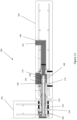
- a straight connection 100 for connecting a first precast wall panel 102 with a precast second wall panel 104.
- the precast wall panels 102, 104 may, for example, be made of concrete and form a structural wall of a building structure.
- Each wall panel 102, 104 has a panel face 103, 105 that refers to the largest surface area of the wall panel 102, 104.
- the straight connection 100 connects the first and second wall panels 102, 104 so that the panel faces 103, 105 are aligned.
- connection has been designed to resist forces imposed on the connections in accordance with the requirements of AS 3600 and AS 3850 in Australia or their equivalent in other areas.
- the straight connection 100 comprises a first connection body 106 that is positioned within the first precast wall panel 102.
- the first connection body 106 was placed in a casting mould (not shown) when the first wall panel 102 was cast.
- a detailed view of the first connection body 106 outside of the wall panel 102 is shown in Figure 3 .
- the straight connection 100 further comprises a second connection body 108 that is positioned within the second precast wall panel 104.
- a detailed view of the second connection body 108 outside of the wall panel 104 is shown in Figure 4 .
- An alternative example of the first connection body 106A is shown in Figure 3A .
- the first connection body 106A functions in the same way as the first connection body 106, however requires less overall material than the first connection body 106.
- connection bodies 106 (106A), 108 have cavities 110 (110A), 112 that extend through an entire length of the connection bodies 106 (106A), 108.
- the cavities 106 (106A), 108 are in the form of tunnels wherein one end of the tunnels terminates at a side face of the wall panel 102, 104 that face each other when the wall panels 102, 104 are connected.
- the cavities may have any suitable shape and length. For example, the cavities may not extend through the entire length of the connection bodies.
- connection bodies 106 (106A), 108 within the wall panels 102, 104 are connected by virtue of a connecting bar 114 and an alignment element 116.
- the connecting bar 114 is in the form of a threaded steel rod, where end portions of the steel rod comprise external threads.
- the external thread may extend along an entire length of the connecting bar. This configuration may simplify the manufacturing process and has some additional advantages as will be described below with regard to a setting material inserted into the connection.
- the alignment element 116 has an overall cylindrical shape and comprises an alignment channel 118 for receiving the connecting bar 114.
- the alignment element 116 also has an external thread 120 located at one end of the alignment element 116 to attach to one of the connection bodies 106 (106A), 108.
- at least one of the cavities 110, 112 of the connection bodies 106 (106A), 108 has an internal thread for engaging with the alignment element 116.
- both cavities 110, 112 of the connection bodies 106, 108 have an internal thread such that the alignment element 116 can be attached to either of the connection bodies 106, 108.
- the alignment element 116 further has an external structure 122 to be manipulated by a tool, such as a spanner or a wrench, to fasten the alignment element 116 to one of the first and second connection bodies 106 (106A), 108.
- the alignment element 116 attaches to one of the connection bodies 106 (106A), 108.
- a detailed view of the wall panels 102, 104 being connected by the connection 100 is illustrated in Figures 6 .
- the alignment element 116 is attached to the second connection body 104.
- the connecting bar 114 is initially positioned within the cavity 112 of the second connection body 104. It should be noted that in this particular example, the cavities 110 (110A), 112 of both connection bodies 102, 104 are dimensioned to fully accommodate the connecting bar 114 to provide flexibility when the precast wall panels 102, 104 are connected.
- connection body 106 106A
- 108 may be dimensioned to accommodate only a portion of the connecting bar 114, such as half a length of the connecting bar 114.
- each cavity 110, 112 may comprise a seat or shoulder portion for seating an end portion of the alignment element 116 to stop further movement of the alignment element 116 into the cavity 110, 112.
- An exemplary shoulder portion 125 of the first connection body 106A is shown in Figure 3A .
- the alignment element 116 further functions as a spacer element between the adjoining precast wall panels 102, 104.
- a dimension of a space between the connected precast wall panels 102, 104 depends on at least a position of the seat or shoulder portion within the cavities 110 (110A), 112, such as shoulder portion 125 of the first connection body 106A, and a length of the alignment element 116.
- Providing a relatively small space between connected precast wall panels 102, 104 has the particular advantage that the so formed wall can allow for vibrations of the wall panels 102, 104. Even more so, a sealing material may be provided in the space between the connected wall panels 102, 104.
- the connecting bar 114 is positioned to extend through the alignment channel 118 of the alignment element 116 and into both cavities 110 (110A), 112. Specifically, the connecting bar 114 is positioned such that the external thread 115 at both ends of the connecting bar 114 can be accessed through openings 124 (124A), 126 for respective fasteners 128, 130.
- the opening 126 is located within a side wall of the connection body 108 and arranged such that the opening 126 is substantially flush with the panel face 105 of the wall panel 104.
- the opening 126 has the function of providing access to the cavity 112 of the connection body 108, for example for the fasteners 130 to engage with the connecting bar 114.
- the connection body 108 further comprises a cap 132 that is configured to seal the opening 126 when the wall panel 108 is cast.
- each fastener 128, 130 comprises a first nut 136, a second nut 138, such as a jam nut, and a washer 140.
- the first nut 136 is configured to engage with the external thread 115 of the connecting bar 114 and fastened against the flat surface 134 of the connection body 108 via the washer 140 to apply a force to the connecting bar 114.
- the second nut 138 is configured to lock the first nut 136 in place.
- any suitable type of fasteners is envisaged that can engage with the external thread portions of the connecting bar 114.
- the connecting bar 114 extends through the alignment element 116 and into the cavities 110 (110A), 112 of the first and second connection bodies 106 (106A), 108 within the precast wall panels 102, 104
- the first and second fasteners 128, 130 can be inserted into the cavities 110 (110A), 112 through the respective openings 124 (124A), 126 to engage with the respective outer threads 115 at the end portions of the connecting bar 114. In this way, opposing forces are applied to the ends of the connecting bar 114 thereby securely connecting the adjoining wall panels 102, 104.
- the straight connection 100 is configured such that a space 142 is formed between the connecting bar 114 and the alignment channel 118.
- a space 142 is formed between the connecting bar 114 and the cavities 110, 112 of the first and second connection bodies 106, 108.
- the straight connection 100 is configured such that the space 142 defines a flow channel for a setting material, such as grout 141 as shown as shaded area in Figure 6 . Filling the formed space 142 with the setting material, such as grout, may improve the strength of the connection 100. It will be appreciated by a person skilled in the art that filling the space 142 with a setting material such as grout is optional and may not be required to securely connect the precast wall panels 102, 104.
- the space 142 is formed by providing a connecting bar 114 that has a smaller diameter than a diameter of the alignment channel 118 and the cavities 110, 112.
- a further advantage of this configuration is that a certain degree of tolerance is provided for aligning the first and second cavities 110, 112 when the precast wall panels 102, 104 are positioned to be connected. This tolerance may further be advantageous if one or both of the wall panels 102, 104 move relative to each other, for example, after the building structure has been erected.
- the alignment element 116 in this particular embodiment also has the function of sealing the formed space 142. In this way, if a setting material, such as grout, is inserted into the connection 100, the setting material can be substantially confined to the space 142 within the connection 100. Thus, by providing the alignment element 116, no or only a limited amount of setting material may move outside of the connection 100.
- the straight connection 100 in this example further comprises a further flow channel, such as grout tube 144 that attaches to the first and/or second connection body 106, 108.
- the grout tube 144 attaches to the second connection body 108 by virtue of a thread 145.
- a person skilled in the art will appreciate that other suitable attachments are envisaged, including but not limited to a sliding connection that may be secured using an adhesive such as tape.
- the grout tube 144 is arranged such that an end of the grout tube 144 terminates at a panel face of a wall panel 104.
- the grout tube 144 attaches to the second connection body 108 to be in fluid communication with the cavity 112 and comprises an elbow 146 such that an end of the grout tube 144 terminates at the second panel face 105.
- a protective cap (not shown) may be attached to the end of the grout tube 114 when the wall panels 102, 104 are cast.
- the connecting bar may have an external thread that extends along the entire length of the connecting bar. This provides the advantage that setting material inserted in the space 142 has a larger surface area to set against. Thus, a stronger connection between the precast wall panels 102, 104 may be provided.
- each connection body 106 (106A), 108 is positioned within a respective precast wall panel 102, 104.
- the connection body 106 (106A), 108 is placed into a casting mould (not shown) together with any components of the wall panel, such as the reinforcing structure 101.
- protective caps such as cap 132 or cap 148, attach to the connection bodies 106 (106A), 108 during the casting process.
- each connection body 106 (106A), 108 comprises a plurality of apertures 149 (149A) for receiving a respective plurality of legs 150.
- each connection body 106 (106A), 108 comprises four legs 150 that are height adjustable.
- Each leg 150 comprises a nut head 152 for engaging with a tool, such as a wrench or a spanner to adjust a length of the legs 150.
- the legs 150 of the connection body 106 (106A), 108 extend in a direction substantially perpendicular to the cavity 110 (110A), 112 of the connection body 106 (106A), 108.
- connection 200 that is configured as a corner connection.
- the corner connection is configured to connect a first precast wall panel 202 with a second precast wall panel 104 to form a corner.
- the corner connection 200 comprises a corner connection body 206 and a straight connection body, such as second connection body 108 of the straight connection 100 described with reference to Figures 1 to 6 .
- Features of the straight connection body of connection 200 are analogous to the features described for the connection 100 and like numerals are used to indicate like components.
- the corner connection 200 also comprises a connecting bar, in this example connecting bar 114, and an alignment element, in this example the alignment element 116.
- the corner connection body 206 also comprises a cavity 210 for receiving a portion of the connecting bar 114.
- the cavity 210 of the corner connection body 206 extends substantially perpendicular to the panel face 203 of the wall panel 202 and due to the arrangement of the wall panel 202, it will be appreciated that a length of the cavity 210 is limited by a thickness of the precast wall panel 202. Thus, the cavity 210 is typically shorter than cavity 112 of the straight connection body 108.
- the corner connection body 206 also has an opening 224 to provide access to the cavity 210, for example for fasteners to engage with the external thread of the connecting bar 114. Due to the position of the corner connection body 206 within the precast wall panel 202, the opening 224 is arranged at an end portion of the corner connection body 206 terminating at a side face of the wall panel 202 instead of the panel face 203.
- the opening 224 can be closed using a cap 248 such that during the casting process of the wall panel, no casting material protrudes into the cavity 210 of the corner connection body 206.
- the opposite end of the cavity 210 can be closed with a cap (not shown).
- the corner connection body 206 comprises a plurality of legs 250 for positioning the corner connection body 206 in a casting mould (not shown) when the wall panel 202 is cast.
- the plurality of legs 250 are adjustable in length to adjust the position of the corner connection body 206 relative to the wall panel 202.
- the legs 250 have nut heads 252 for engaging with a tool.
- the plurality of legs 250 extend in a direction that is substantially parallel to the cavity of the corner connection body 206.
- the corner connection body 206 can be positioned within the wall panel 202 such that when the wall panel 202 and the wall panel 104 are positioned next to one another, the cavity 210 of the corner connection body 206 aligns with the cavity 112 of the straight connection body 108.
- the corner connection body 206 further comprises a flange enclosing the corner connection body 206.
- the flange is configured to hold the plurality of legs 250 and is in this example in the form of a plate, such as a steel plate 254.
- the steel plate 254 comprises a central aperture for receiving the corner connection body 206.
- the corner connection body 206 comprises shoulders to secure the steel plate 254 in relative position.
- the flange further provides the advantage that a surface area of the corner connection body 206 can be increased that engages with surrounding casting material, such as concrete. Thus, stability of the corner connection body 206 within the wall panel 202 can be improved.
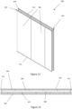
- a non-structural wall 300 which may be used with the present invention.
- a non-structural wall typically forms internal walls within a building structure.
- the non-structural wall panel 300 comprises a first panel layer 302 and a second panel layer 304 that are arranged to extend substantially parallel to one another. This is shown in particular in Figure 13 .
- Each of the first and second panel layers 302, 304 comprises a series of wall panels 306.
- adjoining wall panels 306 of the first and second panel layers 302, 304 are connected by virtue of an abutting joint 307.
- adjoining wall panels 306 abut edge to edge.
- the abutting joint 307 may be filled with a suitable adhesive or glue to strengthen the non-structural wall 300.
- an abutting joint has the particular advantage that manufacturing of the wall panels 306 can be simplified. Even more so, an exemplary sample of the non-structural wall panel 300 with the simplified abutting joints has been thoroughly tested and fulfilled the necessary fire and strength rating.
- the exemplary sample of the non-structural wall 300 was tested for wind loading, fire resistance and acoustic insulation.
- the testing results were the following:
- the first and second panel layers 302, 304 are arranged to enclose a space 308 along and between the two panel layers 302, 304.
- the space 308 may be empty, i.e. filled with air, but is typically filled with an insulating material, such as glass fibre or wool.
- the wall panels 306 of the first and second panel layers 302, 304 are arranged to offset each other.
- an abutting joint 307 of the first panel layer 302 faces a centre portion of a wall panel 306 of the second panel layer 304.
- each wall panel of the first panel layer 302 may substantially face a corresponding wall panel of the second panel layer 304.
- each wall panel 306 comprises a plurality of layers, such as laminated layers.
- the wall panel 306 may comprise outer layers and inner layers.
- the outer layers may be arranged to protect the inner layers and may, for example, be fibre cement layers.
- each fibre cement layer may have a thickness of 4.5 mm.
- the inner layers of the wall panel 306 may comprise a sound shield layer and a fire shield layer.
- the sound shield layer may, for example, be plasterboard with a thickness of 13 mm.
- the fire shield layer may comprise calcium silicate.
- An example of a fire shield layer may be Promatec 100.
- the fire shield layer may have a thickness of 20 mm.
- the described dimensions of the layers are for illustrative purposes only and a person skilled in the art will appreciate that the thickness of each layer may vary depending on the desired strength and fire resistance characteristics of the non-structural wall 300.
- the non-structural wall 300 further comprises a frame structure 310 configured to hold the plurality of wall panels 306 to form the non-structural wall 300.
- the frame structure 310 comprises a frame element provided on each side of the non-structural wall 300.
- the frame structure 310 comprises four frame elements 312.
- Each frame element 312 generally comprises first and second recesses 314, 316, each configured to receive an edge of a wall panel 306, and a spacer 318 component defining the space 306 between the two panel layers 302, 304.
- the non-structural wall 300 may be configured to provide a snug fit between the frame elements 312 and the wall panels 306.
- the frame elements 312 are typically selected based on a thickness of the wall panels 306 and the requirements of the space 306 between the two panel layers 302, 304.
- the wall panels 306 are typically held only by the frame structure 310 enclosing the panel layers 302, 304. As such, no additional frame elements are required that extend through a centre portion of the wall 300. Thus, the amount of material needed for assembling the wall 300 can be further reduced and simplified.
- a total thickness of this exemplary non-structural wall 300 is 175 mm which is thinner than conventional non-structural walls whilst achieving substantially the same strength and fire resistance requirements.
- the non-structural wall 300 may further comprise outer layers 319, such as cladding layers.
- the outer layers 319 may be arranged to cover a portion of the frame elements 312.
- Exemplary outer layers 319 may be plasterboard such as Gyprock or CSR surround.
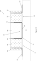
- a first frame element 320 of the frame structure 310 is shown in Figure 14 .
- the first frame element 320 comprises a frame body 321, first and second longitudinal angles 322, 324 and a C-channel beam 326 having a longitudinal web 328 and first and second legs 330, 332 extending from the web 328.
- the first frame element 320 is configured such that a first recess 314 for receiving an edge of the wall panel 306 is formed by a space between the first longitudinal angle 322 and the first leg 330 of the C-channel beam 326.
- a second recess 316 is formed by a space between the second longitudinal angle 324 and the second leg 332 of the C-channel beam 326.
- Suitable fasteners may be used to secure the angles 322, 324 and the C-channel beam 326 to the frame body 321 and the edges of the wall panel 306.
- a width of the longitudinal web 328 of the C-channel beam 326 therefore defines a width of the space between the panel layers 302, 304.
- the frame structure 310 may comprise four first frame elements 320 arranged to form the non-structural wall 300.
- the second frame element 336 comprises a first C-channel beam 338, a second C-channel beam 340 and a spacer web 342 connecting the first and second C-channel beams 338, 340.
- the first and second C-channel beams 338, 340 and the spacer web 342 are integrally formed and therefore form a W-shaped channel 344.
- the second frame element 336 may also comprise a frame body (not shown) and the W-shaped channel 344 may be attached to the frame body using suitable fasteners (not shown).
- the frame structure 310 comprises two first frame elements 320 and two second frame elements 336.
- the two first frame elements 320 may be arranged opposite of each other. However, it will be appreciated that the two first frame elements 320 may alternatively be next to one another.
- the frame structure 310 comprises one first frame element 320 and three second frame elements 336. In yet another specific example, the frame structure 310 comprises three first frame elements 320 and one second frame element 336.
Landscapes
- Engineering & Computer Science (AREA)
- Architecture (AREA)
- Civil Engineering (AREA)
- Structural Engineering (AREA)
- Physics & Mathematics (AREA)
- Electromagnetism (AREA)
- Wood Science & Technology (AREA)
- Life Sciences & Earth Sciences (AREA)
- Manufacturing & Machinery (AREA)
- Chemical & Material Sciences (AREA)
- Ceramic Engineering (AREA)
- Mechanical Engineering (AREA)
- Joining Of Building Structures In Genera (AREA)
- Load-Bearing And Curtain Walls (AREA)
Claims (12)
- Verbindung (100, 200) zum Verbinden von angrenzenden vorgefertigten Wandplatten (102, 104, 202), wobei die Verbindung (100, 200) umfasst:eine Verbindungsstange (114), die an jedem Endabschnitt der Verbindungsstange (114) ein Außengewinde (115) umfasst;erste und zweite Verbindungskörper (106, 108, 206), die jeweils einen Hohlraum (110, 112, 210) zum Aufnehmen mindestens eines Abschnitts der Verbindungsstange (114) umfassen und dazu konfiguriert sind, innerhalb einer jeweiligen vorgefertigten Wandplatte (102, 104, 202) so positioniert werden, dass, wenn die vorgefertigten Wandplatten (102, 104, 202) verbunden sind, der Hohlraum (110, 210) des ersten Verbindungskörpers (106, 206) im Wesentlichen mit dem Hohlraum (112) des zweiten Verbindungskörpers (108) ausgerichtet ist;erste und zweite Befestigungselemente (128, 130, 228), die dazu konfiguriert sind, in die jeweiligen Außengewinde (115) der Verbindungsstange (114) einzugreifen;dadurch gekennzeichnet, dass die Verbindung ein Ausrichtungselement (116) zum Ausrichten der Hohlräume (110, 112, 210) der ersten und zweiten Verbindungskörper (106, 108, 206) umfasst, wobei das Ausrichtungselement (116) einen Ausrichtungskanal (118) zum Aufnehmen der Verbindungsstange (114) umfasst;
unddass die Verbindung (100, 200) so konfiguriert ist, dass, wenn sich die Verbindungsstange (114) durch den Ausrichtungskanal (118) des Ausrichtungselements (116) und in die Hohlräume (110, 112, 210) der ersten und zweiten Verbindungskörper (106, 108, 206) erstreckt, die innerhalb der vorgefertigten Wandplatten (102, 104, 202) positioniert sind, die ersten und zweiten Befestigungselemente (128, 130, 228) in die jeweiligen Außengewinde (115) der Verbindungsstange (114) eingreifen zu können, um entgegengesetzte Kräfte auf die Verbindungsstange (114) auszuüben und dadurch die angrenzenden Wandplatten (102, 104, 202) zu verbinden, und ein abgedichteter Raum (142) zwischen der Verbindungsstange (114) und dem Ausrichtungskanal (118) des Ausrichtungselements (116) gebildet wird, der einen Strömungskanal zwischen den Hohlräumen (110, 112) zur Aufnahme eines aushärtenden Materials definiert. - Verbindung (100, 200) nach Anspruch 1, wobei das Ausrichtungselement (116) ein Außengewinde (120) zum Eingreifen in ein Innengewinde des ersten oder zweiten Verbindungskörpers (106, 108, 206) umfasst.
- Verbindung (100, 200) nach Anspruch 1 oder 2, wobei die Verbindungsstange (114) ein Außengewinde (115) aufweist, das sich über die gesamte Länge der Verbindungsstange (114) erstreckt.
- Verbindung (100, 200) nach einem der Ansprüche 1 bis 3, wobei jeder Verbindungskörper (106, 108, 206) eine Vielzahl von Beinen (150, 250) zum Positionieren des Verbindungskörpers (106, 108, 206) in einer Gussform umfasst, wenn die Wandplatte (102, 104, 202) gegossen wird.
- Verbindung (100, 200) nach Anspruch 4, wobei jedes der Vielzahl von Beinen (150, 250) in der Länge so einstellbar ist, dass eine Position des Verbindungskörpers (106, 108, 206) eingestellt werden kann.
- Verbindung (100, 200) nach einem der Ansprüche 1 bis 5 und angrenzende vorgefertigte Wandplatten, wobei die Verbindung (100, 200) als eine gerade Verbindung (100) zum Verbinden angrenzender vorgefertigter Wandplatten (102, 104) zur Bildung einer geraden Wand oder als eine Eckverbindung (200) zum Verbinden angrenzender vorgefertigter Wandplatten (202, 104) zur Bildung einer Ecke konfiguriert ist,wobei, wenn die Verbindung als eine gerade Verbindung (100) konfiguriert ist, jeder der ersten und zweiten Verbindungskörper als gerade Verbindungskörper (106, 108) konfiguriert ist, wobei sich der Hohlraum (110, 112) jedes geraden Verbindungskörpers (106, 108) im Wesentlichen parallel zur Plattenfläche (103, 105) der Wandplatte (102, 104) erstreckt, undwobei, wenn die Verbindung als eine Eckverbindung (200) konfiguriert ist, der erste Verbindungskörper als ein Eckverbindungskörper (206) konfiguriert ist und der zweite Verbindungskörper als ein gerader Verbindungskörper (108) konfiguriert ist, wobei sich ein Hohlraum (210) des Eckverbindungskörpers (206) im Wesentlichen senkrecht zur Plattenfläche (203) der jeweiligen Wandplatte (202) erstreckt.
- Verbindung (100, 200) und angrenzende vorgefertigte Wandplatten nach Anspruch 6, wobei eine Länge des Hohlraums (210) des Eckverbindungskörpers (206) gleich oder kürzer als eine Dicke der jeweiligen vorgefertigten Wandplatte (202) ist.
- Verbindung (100, 200) und angrenzende vorgefertigte Wandplatten nach Anspruch 6 oder 7, wobei, wenn der Verbindungskörper (106,108, 206) eine Vielzahl von Beinen (150, 250) zum Positionieren des Verbindungskörpers (106, 108, 206) umfasst, sich die Vielzahl von Beinen (150) des geraden Verbindungskörpers (106, 108) in eine Richtung erstrecken, die im Wesentlichen senkrecht zu dem Hohlraum (110, 112) des Verbindungskörpers (106, 108) ist, und sich die Vielzahl von Beinen (250) des Eckverbindungskörpers (206) in eine Richtung erstrecken, die im Wesentlichen parallel zu dem Hohlraum (210) des Verbindungskörpers (206) ist.
- Verbindung (100, 200) bzw. Verbindung und angrenzende vorgefertigte Wandplatten nach einem der Ansprüche 1 bis 8, ferner umfassend mindestens ein Mörtel-rohr (144), das dazu konfiguriert ist, einen Hohlraum (110, 112, 210) des ersten und/oder zweiten Verbindungskörpers (106, 108, 206) mit einer Plattenfläche (103, 105, 203) der Wandplatte (102, 104, 202) zu verbinden.
- Verbindung (100, 200) bzw. Verbindung und angrenzende vorgefertigte Wandplatten nach einem der Ansprüche 1 bis 9, wobei jeder Verbindungskörper (106, 108, 206) eine Öffnung (124, 126, 224) zu einer Seitenwand des Hohlraums (110, 112, 210) innerhalb des Verbindungskörpers (106, 108, 206) umfasst, wobei die Öffnung (124, 126, 224) dazu angeordnet ist, den Befestigungselementen (128, 130) Zugang zum Außengewinde (115) der Verbindungsstange (114) bereitzustellen.
- Verbindung (100, 200) bzw. Verbindung und angrenzende vorgefertigte Wandplatten nach Anspruch 10, wobei die Verbindung (100, 200) so konfiguriert ist,
dass die Öffnung (124, 126, 224) im Wesentlichen bündig mit einer Plattenfläche (103, 105, 203) der Wandplatte (102, 104, 202) ist. - Verfahren zum Verbinden von angrenzenden vorgefertigten Wandplatten (102, 104, 202) unter Verwendung der Verbindung bzw. Verbindung und angrenzender vorgefertigter Wandplatten nach einem der Ansprüche 1 bis 11, wobei das Verfahren umfasst:Bereitstellen erster und zweiter vorgefertigter Wandplatten (102, 104, 202) mit jeweiligen ersten und zweiten Verbindungskörpern (106, 108, 206) der Verbindung nach einem der Ansprüche 1 bis 11, die so konfiguriert sind, dass, wenn die vorgefertigten Wandplatten (102, 104, 202) verbunden sind, ein Hohlraum (110, 210) des ersten Verbindungskörpers (106) im Wesentlichen mit einem Hohlraum (112) des zweiten Verbindungskörpers (108) ausgerichtet ist;Bereitstellen und Befestigen des Ausrichtungselements (116) an dem ersten Verbindungskörper (106, 206) derart, dass der Hohlraum (110, 210) des ersten Verbindungskörpers (106, 206) mit einem Ausrichtungskanal (118) des Ausrichtungselements (116) ausgerichtet ist;Bereitstellen und Positionieren einer Verbindungsstange (114) innerhalb zumindest des Hohlraums (110, 210) des ersten Verbindungskörpers (106, 206), wobei die Verbindungsstange (114) an jedem Endabschnitt der Verbindungsstange (114) ein Außengewinde (115) umfasst;Positionieren der zweiten Wandplatte (104) derart, dass die jeweiligen Hohlräume (110, 112, 210) des ersten und zweiten Verbindungskörpers (106, 108, 206) unter Verwendung des Ausrichtungselements (116) ausgerichtet sind;Positionieren der Verbindungsstange (114), um sich durch das Ausrichtungselement (116) und in die Hohlräume (110, 112, 210) des ersten und zweiten Verbindungskörpers (106, 108, 206) zu erstrecken;Eingreifen erster und zweiter Befestigungselemente (128, 130) in die jeweiligen Außengewinde (115) der Verbindungsstange (114), um entgegengesetzte Kräfte auf die Verbindungsstange (114) auszuüben und dadurch die angrenzenden Wandplatten (102, 104, 202) zu verbinden,Füllen des Raums zwischen der Verbindungsstange (114) und dem Ausrichtungselement (116) sowie der ersten und zweiten Hohlräume (110, 112) der jeweiligen ersten und zweiten Verbindungskörper (106, 108) mit einem aushärtenden Material.
Applications Claiming Priority (2)
| Application Number | Priority Date | Filing Date | Title |
|---|---|---|---|
| AU2018903481A AU2018903481A0 (en) | 2018-09-14 | A connection for connecting precast wall panels | |
| PCT/AU2019/050926 WO2020051628A1 (en) | 2018-09-14 | 2019-09-02 | A connection for connecting precast wall panels |
Publications (4)
| Publication Number | Publication Date |
|---|---|
| EP3850165A1 EP3850165A1 (de) | 2021-07-21 |
| EP3850165A4 EP3850165A4 (de) | 2022-05-18 |
| EP3850165C0 EP3850165C0 (de) | 2024-11-20 |
| EP3850165B1 true EP3850165B1 (de) | 2024-11-20 |
Family
ID=69776487
Family Applications (1)
| Application Number | Title | Priority Date | Filing Date |
|---|---|---|---|
| EP19860089.2A Active EP3850165B1 (de) | 2018-09-14 | 2019-09-02 | Verbindung zum verbinden von vorgefertigten wandplatten |
Country Status (5)
| Country | Link |
|---|---|
| EP (1) | EP3850165B1 (de) |
| CN (2) | CN112996966A (de) |
| AU (2) | AU2019339917B2 (de) |
| SG (1) | SG11202102560SA (de) |
| WO (1) | WO2020051628A1 (de) |
Families Citing this family (8)
| Publication number | Priority date | Publication date | Assignee | Title |
|---|---|---|---|---|
| CN112854434B (zh) * | 2021-01-15 | 2022-05-20 | 浙江工业大学 | 一种高强保温内嵌挂件的匀质被动房建筑模块 |
| KR102644511B1 (ko) * | 2021-10-01 | 2024-03-08 | 계명대학교 산학협력단 | 매립형 포스트 텐션을 이용한 pc벽체의 수직접합장치 및 시공방법 |
| CN115142553B (zh) * | 2022-07-18 | 2023-07-18 | 山东大学 | 多层装配式混凝土板式结构房屋及其安装方法 |
| CN115288358B (zh) * | 2022-07-26 | 2023-07-18 | 昆明华城兴建材有限公司 | 一种纤维增强水泥板内置固定网架 |
| CN115928905A (zh) * | 2022-12-28 | 2023-04-07 | 中化学曙光建设有限公司 | 一种装配式建筑墙体及安装方法 |
| DE102023118880A1 (de) * | 2023-07-17 | 2025-01-23 | Schöck Bauteile GmbH | Modul zum Befüllen eines Einbauelementes, Einbauelement für ein Fertigteilelement, Fertigteilelement aus Beton und Verfahren zur Herstellung eines Fertigteilelementes |
| CN118241777B (zh) * | 2024-05-20 | 2024-07-30 | 成都建工第六建筑工程有限公司 | 一种装配式建筑墙体结构和加固结构 |
| CN120350773B (zh) * | 2025-06-24 | 2025-10-03 | 成都建工路桥建设有限公司 | 一种墙体结构 |
Family Cites Families (9)
| Publication number | Priority date | Publication date | Assignee | Title |
|---|---|---|---|---|
| US3230683A (en) * | 1963-05-06 | 1966-01-25 | Clayton D Foster | Overlapped precast panels and fastening means connecting the same |
| US5309691A (en) * | 1992-02-26 | 1994-05-10 | Tolliver Wilbur E | Shear connected structural units |
| KR100770006B1 (ko) * | 2006-12-13 | 2007-10-25 | 박정진 | Pc기둥 수직연결철근의 보강구조 |
| KR101433654B1 (ko) * | 2012-08-09 | 2014-08-26 | 동아이엔지(주) | 프리캐스트 콘크리트용 슬리브 리브 조인트, 이를 구비한 프리캐스트 콘크리트 제조방법 및 이를 구비한 프리캐스트 콘크리트 구조물의 시공방법 |
| EP4273343A3 (de) * | 2014-04-07 | 2024-01-03 | NXT Building System Pty Ltd. | Schraubpfahl zum tragen einer baukonstruktion |
| AT516415B1 (de) * | 2014-10-15 | 2016-07-15 | KAPPA Filter Systems GmbH | Verbindungsvorrichtung zur mechanischen Kopplung von Betonplatten, sowie damit aufgebaute Betonwand |
| CN104563299B (zh) * | 2015-01-15 | 2017-10-24 | 建研科技股份有限公司 | 钢筋混凝土预制组件及安装方法 |
| WO2017137800A1 (en) * | 2016-02-08 | 2017-08-17 | Zamyslowski Eugeniusz | A building construction and a method for joining elements of building constructions |
| CN205712492U (zh) * | 2016-05-05 | 2016-11-23 | 中民筑友科技投资有限公司 | 一种连接件 |
-
2019
- 2019-09-02 CN CN201980074062.8A patent/CN112996966A/zh active Pending
- 2019-09-02 AU AU2019339917A patent/AU2019339917B2/en active Active
- 2019-09-02 EP EP19860089.2A patent/EP3850165B1/de active Active
- 2019-09-02 WO PCT/AU2019/050926 patent/WO2020051628A1/en not_active Ceased
- 2019-09-02 SG SG11202102560SA patent/SG11202102560SA/en unknown
- 2019-09-16 CN CN201921532536.2U patent/CN211850121U/zh active Active
-
2023
- 2023-12-20 AU AU2023285770A patent/AU2023285770A1/en not_active Abandoned
Also Published As
| Publication number | Publication date |
|---|---|
| EP3850165A4 (de) | 2022-05-18 |
| EP3850165A1 (de) | 2021-07-21 |
| AU2019339917A1 (en) | 2021-05-13 |
| CN112996966A (zh) | 2021-06-18 |
| EP3850165C0 (de) | 2024-11-20 |
| AU2019339917B2 (en) | 2023-09-21 |
| WO2020051628A1 (en) | 2020-03-19 |
| SG11202102560SA (en) | 2021-04-29 |
| CN211850121U (zh) | 2020-11-03 |
| AU2023285770A1 (en) | 2024-01-18 |
Similar Documents
| Publication | Publication Date | Title |
|---|---|---|
| EP3850165B1 (de) | Verbindung zum verbinden von vorgefertigten wandplatten | |
| US7637076B2 (en) | Moment-resistant building column insert system and method | |
| WO1997037090A1 (en) | Unitized post and panel building system | |
| US20230358039A1 (en) | Wall panel module comprising dual gasket assembly | |
| US12584309B2 (en) | Process for making a paneled wall having abutment joints sealed by a dual gasket assembly | |
| US12577777B2 (en) | Paneled wall system comprising a dual gasket assembly | |
| US20230358055A1 (en) | Dual gasket assembly for sealing panel-to-panel joints | |
| US20230383536A1 (en) | Assembly processes for making a wall panel module comprising a dual gasket assembly | |
| EP4519514A1 (de) | Wasserabflusskanal für doppeldichtungsanordnung | |
| JP4095534B2 (ja) | ラーメン構造体における柱と梁との仕口構造及びその施工方法 | |
| KR102153857B1 (ko) | Pc패널 연결용 커플러 | |
| HK40058824B (en) | A connection for connecting precast wall panels | |
| HK40058824A (en) | A connection for connecting precast wall panels | |
| Scotta et al. | Engineered aluminium beams for anchoring timber buildings to foundation | |
| JP4045502B2 (ja) | 構造物 | |
| JP2021050507A (ja) | 座屈拘束ブレース | |
| JP7769843B1 (ja) | 制震架構及び制震架構の構築方法 | |
| KR102869012B1 (ko) | 하이브리드 내진 보강구조 및 그 시공방법 | |
| JP2005023612A (ja) | プレキャストコンクリート躯体及びそれを用いた建築物並びにその建設工法 | |
| JP7780151B2 (ja) | 木質材料からなる壁部材の設置構造 | |
| KR102239574B1 (ko) | 무앵커 기둥 철골 접합형 내진 보강 시스템 및 보강 방법 | |
| WO2025234299A1 (ja) | 制震架構及び制震架構の構築方法 | |
| GB2207155A (en) | Prefabricated building system | |
| JP2024176523A (ja) | 木質パネルの接合部材及び同部材を用いた接合部構造 | |
| CN121066281A (zh) | 一种用于装配式墙板的竖向拼缝盒式连接装置及施工方法 |
Legal Events
| Date | Code | Title | Description |
|---|---|---|---|
| STAA | Information on the status of an ep patent application or granted ep patent |
Free format text: STATUS: THE INTERNATIONAL PUBLICATION HAS BEEN MADE |
|
| PUAI | Public reference made under article 153(3) epc to a published international application that has entered the european phase |
Free format text: ORIGINAL CODE: 0009012 |
|
| STAA | Information on the status of an ep patent application or granted ep patent |
Free format text: STATUS: REQUEST FOR EXAMINATION WAS MADE |
|
| 17P | Request for examination filed |
Effective date: 20210413 |
|
| AK | Designated contracting states |
Kind code of ref document: A1 Designated state(s): AL AT BE BG CH CY CZ DE DK EE ES FI FR GB GR HR HU IE IS IT LI LT LU LV MC MK MT NL NO PL PT RO RS SE SI SK SM TR |
|
| DAV | Request for validation of the european patent (deleted) | ||
| DAX | Request for extension of the european patent (deleted) | ||
| REG | Reference to a national code |
Ref country code: HK Ref legal event code: DE Ref document number: 40058824 Country of ref document: HK |
|
| A4 | Supplementary search report drawn up and despatched |
Effective date: 20220420 |
|
| RIC1 | Information provided on ipc code assigned before grant |
Ipc: F16B 7/18 20060101ALI20220412BHEP Ipc: E04C 2/00 20060101ALI20220412BHEP Ipc: E04C 2/52 20060101ALI20220412BHEP Ipc: E04C 2/40 20060101ALI20220412BHEP Ipc: E04C 2/38 20060101ALI20220412BHEP Ipc: E04C 2/34 20060101ALI20220412BHEP Ipc: E04C 2/24 20060101ALI20220412BHEP Ipc: E04C 2/06 20060101ALI20220412BHEP Ipc: E04C 2/04 20060101ALI20220412BHEP Ipc: E04B 2/84 20060101ALI20220412BHEP Ipc: E04B 2/68 20060101ALI20220412BHEP Ipc: E04B 1/16 20060101ALI20220412BHEP Ipc: B28B 23/00 20060101ALI20220412BHEP Ipc: E04C 5/16 20060101ALI20220412BHEP Ipc: E04B 1/61 20060101ALI20220412BHEP Ipc: E04B 1/41 20060101ALI20220412BHEP Ipc: E04B 1/04 20060101AFI20220412BHEP |
|
| GRAP | Despatch of communication of intention to grant a patent |
Free format text: ORIGINAL CODE: EPIDOSNIGR1 |
|
| STAA | Information on the status of an ep patent application or granted ep patent |
Free format text: STATUS: GRANT OF PATENT IS INTENDED |
|
| INTG | Intention to grant announced |
Effective date: 20230609 |
|
| GRAJ | Information related to disapproval of communication of intention to grant by the applicant or resumption of examination proceedings by the epo deleted |
Free format text: ORIGINAL CODE: EPIDOSDIGR1 |
|
| STAA | Information on the status of an ep patent application or granted ep patent |
Free format text: STATUS: REQUEST FOR EXAMINATION WAS MADE |
|
| GRAP | Despatch of communication of intention to grant a patent |
Free format text: ORIGINAL CODE: EPIDOSNIGR1 |
|
| STAA | Information on the status of an ep patent application or granted ep patent |
Free format text: STATUS: GRANT OF PATENT IS INTENDED |
|
| INTC | Intention to grant announced (deleted) | ||
| INTG | Intention to grant announced |
Effective date: 20231030 |
|
| GRAJ | Information related to disapproval of communication of intention to grant by the applicant or resumption of examination proceedings by the epo deleted |
Free format text: ORIGINAL CODE: EPIDOSDIGR1 |
|
| STAA | Information on the status of an ep patent application or granted ep patent |
Free format text: STATUS: REQUEST FOR EXAMINATION WAS MADE |
|
| GRAP | Despatch of communication of intention to grant a patent |
Free format text: ORIGINAL CODE: EPIDOSNIGR1 |
|
| STAA | Information on the status of an ep patent application or granted ep patent |
Free format text: STATUS: GRANT OF PATENT IS INTENDED |
|
| INTC | Intention to grant announced (deleted) | ||
| INTG | Intention to grant announced |
Effective date: 20240326 |
|
| GRAS | Grant fee paid |
Free format text: ORIGINAL CODE: EPIDOSNIGR3 |
|
| GRAJ | Information related to disapproval of communication of intention to grant by the applicant or resumption of examination proceedings by the epo deleted |
Free format text: ORIGINAL CODE: EPIDOSDIGR1 |
|
| GRAL | Information related to payment of fee for publishing/printing deleted |
Free format text: ORIGINAL CODE: EPIDOSDIGR3 |
|
| STAA | Information on the status of an ep patent application or granted ep patent |
Free format text: STATUS: REQUEST FOR EXAMINATION WAS MADE |
|
| GRAJ | Information related to disapproval of communication of intention to grant by the applicant or resumption of examination proceedings by the epo deleted |
Free format text: ORIGINAL CODE: EPIDOSDIGR1 |
|
| GRAL | Information related to payment of fee for publishing/printing deleted |
Free format text: ORIGINAL CODE: EPIDOSDIGR3 |
|
| INTC | Intention to grant announced (deleted) | ||
| GRAP | Despatch of communication of intention to grant a patent |
Free format text: ORIGINAL CODE: EPIDOSNIGR1 |
|
| STAA | Information on the status of an ep patent application or granted ep patent |
Free format text: STATUS: GRANT OF PATENT IS INTENDED |
|
| INTC | Intention to grant announced (deleted) | ||
| INTG | Intention to grant announced |
Effective date: 20240912 |
|
| GRAA | (expected) grant |
Free format text: ORIGINAL CODE: 0009210 |
|
| STAA | Information on the status of an ep patent application or granted ep patent |
Free format text: STATUS: THE PATENT HAS BEEN GRANTED |
|
| AK | Designated contracting states |
Kind code of ref document: B1 Designated state(s): AL AT BE BG CH CY CZ DE DK EE ES FI FR GB GR HR HU IE IS IT LI LT LU LV MC MK MT NL NO PL PT RO RS SE SI SK SM TR |
|
| REG | Reference to a national code |
Ref country code: GB Ref legal event code: FG4D |
|
| RIN1 | Information on inventor provided before grant (corrected) |
Inventor name: LIM, MATAKII |
|
| REG | Reference to a national code |
Ref country code: CH Ref legal event code: EP |
|
| REG | Reference to a national code |
Ref country code: DE Ref legal event code: R096 Ref document number: 602019062371 Country of ref document: DE |
|
| REG | Reference to a national code |
Ref country code: IE Ref legal event code: FG4D |
|
| U01 | Request for unitary effect filed |
Effective date: 20241213 |
|
| U07 | Unitary effect registered |
Designated state(s): AT BE BG DE DK EE FI FR IT LT LU LV MT NL PT RO SE SI Effective date: 20241223 |
|
| U1N | Appointed representative for the unitary patent procedure changed after the registration of the unitary effect |
Representative=s name: HARRISON IP LIMITED; GB |
|
| PG25 | Lapsed in a contracting state [announced via postgrant information from national office to epo] |
Ref country code: HR Free format text: LAPSE BECAUSE OF FAILURE TO SUBMIT A TRANSLATION OF THE DESCRIPTION OR TO PAY THE FEE WITHIN THE PRESCRIBED TIME-LIMIT Effective date: 20241120 Ref country code: IS Free format text: LAPSE BECAUSE OF FAILURE TO SUBMIT A TRANSLATION OF THE DESCRIPTION OR TO PAY THE FEE WITHIN THE PRESCRIBED TIME-LIMIT Effective date: 20250320 |
|
| PG25 | Lapsed in a contracting state [announced via postgrant information from national office to epo] |
Ref country code: ES Free format text: LAPSE BECAUSE OF FAILURE TO SUBMIT A TRANSLATION OF THE DESCRIPTION OR TO PAY THE FEE WITHIN THE PRESCRIBED TIME-LIMIT Effective date: 20241120 |
|
| PG25 | Lapsed in a contracting state [announced via postgrant information from national office to epo] |
Ref country code: NO Free format text: LAPSE BECAUSE OF FAILURE TO SUBMIT A TRANSLATION OF THE DESCRIPTION OR TO PAY THE FEE WITHIN THE PRESCRIBED TIME-LIMIT Effective date: 20250220 |
|
| PG25 | Lapsed in a contracting state [announced via postgrant information from national office to epo] |
Ref country code: GR Free format text: LAPSE BECAUSE OF FAILURE TO SUBMIT A TRANSLATION OF THE DESCRIPTION OR TO PAY THE FEE WITHIN THE PRESCRIBED TIME-LIMIT Effective date: 20250221 |
|
| PG25 | Lapsed in a contracting state [announced via postgrant information from national office to epo] |
Ref country code: PL Free format text: LAPSE BECAUSE OF FAILURE TO SUBMIT A TRANSLATION OF THE DESCRIPTION OR TO PAY THE FEE WITHIN THE PRESCRIBED TIME-LIMIT Effective date: 20241120 |
|
| PG25 | Lapsed in a contracting state [announced via postgrant information from national office to epo] |
Ref country code: RS Free format text: LAPSE BECAUSE OF FAILURE TO SUBMIT A TRANSLATION OF THE DESCRIPTION OR TO PAY THE FEE WITHIN THE PRESCRIBED TIME-LIMIT Effective date: 20250220 |
|
| PG25 | Lapsed in a contracting state [announced via postgrant information from national office to epo] |
Ref country code: SM Free format text: LAPSE BECAUSE OF FAILURE TO SUBMIT A TRANSLATION OF THE DESCRIPTION OR TO PAY THE FEE WITHIN THE PRESCRIBED TIME-LIMIT Effective date: 20241120 |
|
| PG25 | Lapsed in a contracting state [announced via postgrant information from national office to epo] |
Ref country code: SK Free format text: LAPSE BECAUSE OF FAILURE TO SUBMIT A TRANSLATION OF THE DESCRIPTION OR TO PAY THE FEE WITHIN THE PRESCRIBED TIME-LIMIT Effective date: 20241120 |
|
| PG25 | Lapsed in a contracting state [announced via postgrant information from national office to epo] |
Ref country code: CZ Free format text: LAPSE BECAUSE OF FAILURE TO SUBMIT A TRANSLATION OF THE DESCRIPTION OR TO PAY THE FEE WITHIN THE PRESCRIBED TIME-LIMIT Effective date: 20241120 |
|
| PLBE | No opposition filed within time limit |
Free format text: ORIGINAL CODE: 0009261 |
|
| STAA | Information on the status of an ep patent application or granted ep patent |
Free format text: STATUS: NO OPPOSITION FILED WITHIN TIME LIMIT |
|
| 26N | No opposition filed |
Effective date: 20250821 |